

Page 1
RICOH Technical
Bulletin
PAGE: 1/7
Model:
Subject:
From:
Classification:
Penguin (Little, Crest, Emperor)
Duplex Jam Information
GTSS Field Information Dept.
Troubleshooting
Mechanical
Paper path
Other ( )
1. Stacking in the duplex feed section
A
D
F
Part information
Electrical
Transmit/receive
B
Date:
30-Nov-98
Prepared by:
C
No.: 1
H.K
Action required
Service manual revision
Retrofit information
E
G
I
H
J
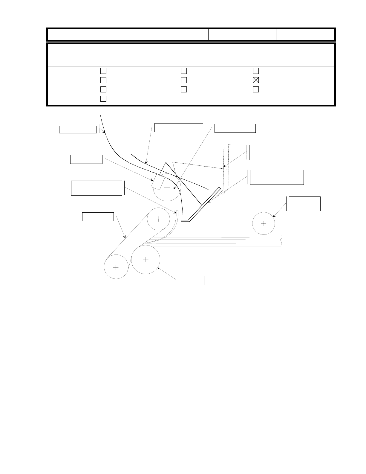
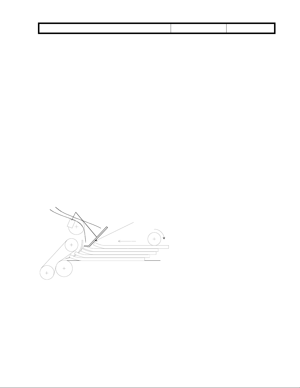
Duplex entrance
Fig. 1
A: Outer inverter guide, B: Inner inverter guide, C: Duplex transport brush roller,
D: Duplex transport sensor, E: Upper position of paper guide, F: Paper holding mylar,
G: Lower position of paper guide, H: Separation belt, I: positioning roller, J: Feed roller
- Stacking mechanism -
Paper comes in down the inverter guides, and pushes the paper guide up [E].
·
Paper starts to enter the duplex tray.
·
After the trailing edge of the paper passes the duplex transport sensor [D], the paper
·
guide falls into place [G].
The brush roller [C] pushes the trailing edge of the paper so that the paper is not
·
caught in the inverter guides [A and B].
At the appropriate time after the trailing edge of the paper passes through the duplex
·
transport sensor, the positioning roller starts to rotate to deliver the paper to the duplex
feed section. The paper guide directs the paper under the mylar ([F] on the previous
page) so that the paper stacks correctly in the duplex feed section.
Page 2
RICOH Technical
Bulletin
PAGE: 2/7
Model:
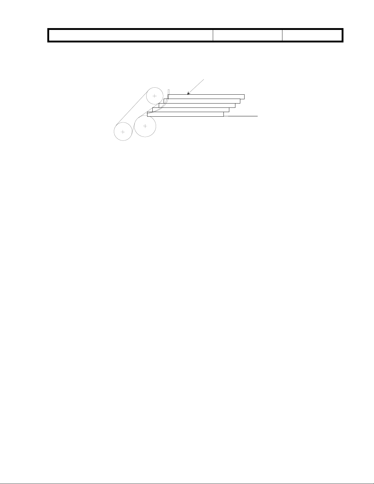
- Correct stacking condition -
Penguin (Little, Crest, Emperor)
The pages delivered by the positioning roller are stacked along the separation belt like
a staircase as shown in fig. 2. The paper holding mylar guides the paper and holds the
leading edge in the correct position for duplex feed.
Correct stacking condition
Fig. 2
Date:
Staircase stacking
30-Nov-98
No.: 1
Page 3
RICOH Technical
Bulletin
PAGE: 3/7
Model:
Penguin (Little, Crest, Emperor)
Date:
30-Nov-98
No.: 1
2. Duplex jam troubleshooting
Duplex jams can be caused by differences in the width of various paper brands, bad
condition of the inner inverter guide, or curled paper. The following troubleshooting
information is for these causes.
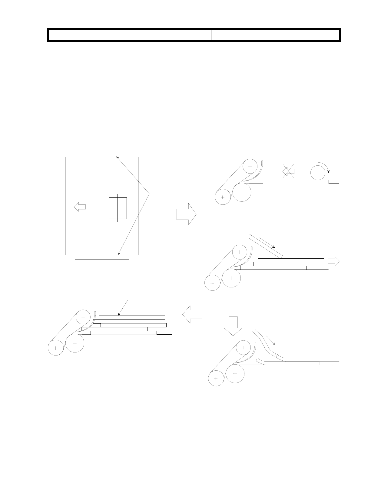
2-1. Paper wider than jogger fence span
2-1-1. Cause
If the interval between the jogger fences is less than the paper width, the positioning
roller cannot deliver the paper to the duplex feed position because of friction as the
paper rubs against the joggers. Then, duplex jams occur.
Fig. 4
Friction
Fig. 3 The jogger fence
span is less than the
paper width
Pattern 1
Not staircase stackin
This condition causes double feed and/or non feed.
Paper is not delivered to the feed
section.
Fig. 5
g
The paper holding mylar does not hold the stacked
paper properly. The next sheet pushes the stacked
paper back.
Pattern 2
Page 4
RICOH Technical
Bulletin
PAGE: 4/7
Model:
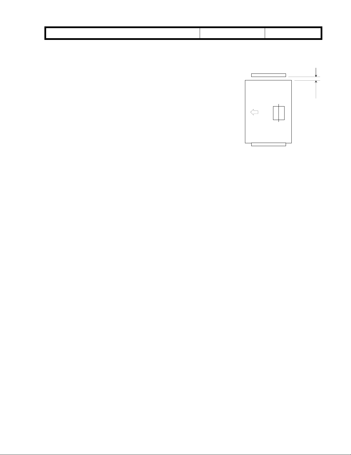
2-1-2. Duplex jogger fence span adjustment
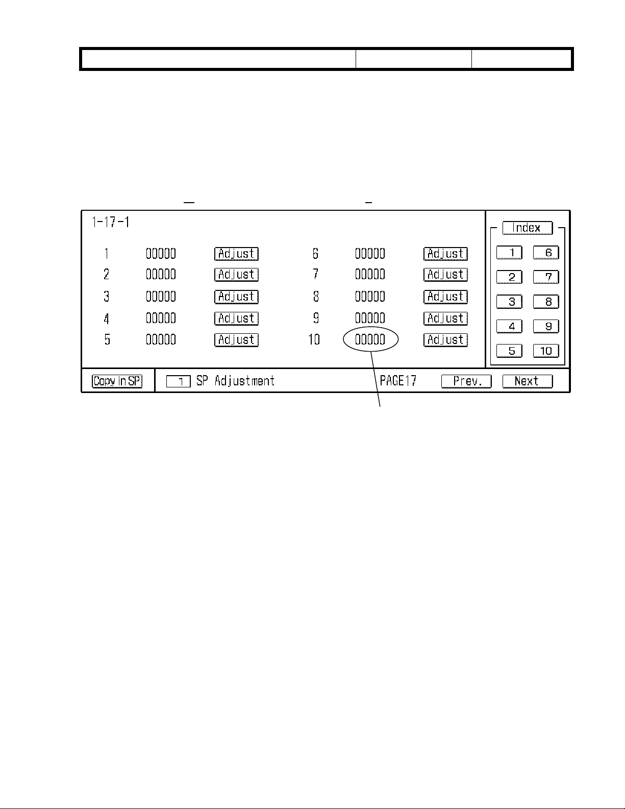
1) By accessing SP1-7-1 (jogger span adjustment), check
2) Feed and stack one sheet of the paper of the size and
3) Open the front door, and gently pull out the duplex tray.
4) Measure the distance between rear jogger fence and
5) If the distance is not within this limit, adjust the jogger
Penguin (Little, Crest, Emperor)
the jogger sp an adjustment setting.
brand normally used in the duplex tray.
paper (3 times or more).
Adjustment standard: A = 0.5 to 1.5 mm
fence span by changing the SP mode value. Input a
wider value than you want at first, then reduce it – this
is necessary because there is a little play in the
mechanism. If the SP mode is changed from narrower
to wider, paper buckling may appear.
SP1-7-1: 0.3 mm/step
– key: Wider span, + key: Narrower spa n
Date:
30-Nov-98
Fig. 8
No.: 1
A
2-2. Deformed inner inverter guide
2-2-1. Cause
If the inner inverter guide (A2474433: Inverter Guide Plate) in the inverter unit is deformed
(for example, due to a manufacturer error), the magnets on the inner inverter guide may
not attract the outer inverter guide. Then, jams may occur when the paper enters the
duplex unit.
2-2-2. Check points for the inner inverter guide
1) When paper is stacking in the duplex unit, check if the inner inverter guide vibrates.
2) Remove the paper exit unit (refer to paper exit unit removal on page 6-121 of the
service manual). Check if the magnets on the inner inverter guide attract the outer
inverter guide.
3) If the magnets do not attract the outer inverter guide, replace the inner inverter guide.
Make sure that the magnets on the new inverter guide attract the outer inverter guide.
Page 5
RICOH Technical
Bulletin
PAGE: 5/7
Model:
2-3. Paper curl
2-3-1. Cause
Paper with a large curl (height:15 mm or more) may cause stacking failure. There are two
stacking failure patterns. Refer to patterns 1 and 2 on page 3.
2-3-2. Procedure for checking curl height
1) Raise the positioning roller by securing the positioning roller bracket with tape so that
2) Feed and stack one sheet of the paper of the size and brand normally used in the
3) Open the front door and pull out the duplex unit quickly.
4) Measure the height of the curl at the front and rear edges of the curled side of the
5) Turn the paper upside-down and repeat the above procedure three times. Find the
The paper guide can stack curled paper fairly well, as shown in Fig. 9. However, strongly
curled paper cannot be guided properly, so jams may occur. In this case, set the paper in
accordance with steps 4 and 5 in the above procedure.
Penguin (Little, Crest, Emperor)
the positioning roller does not drop.
duplex tray.
paper.
Note:
smaller curl height and set the paper so that the curl height is smaller when paper
enters the duplex tray.
During measurement the curl height may change; measure the height quickly.
Date:
30-Nov-98
No.: 1
Fig. 9
Paper is guided
Paper curled face-up is delivered to the feed
position correctly when the paper guide is at
the lower position.
Page 6
RICOH Technical
Bulletin
PAGE: 6/7
Model:
Penguin (Little, Crest, Emperor)
Date:
30-Nov-98
No.: 1
2-3-3. Strongly curled paper
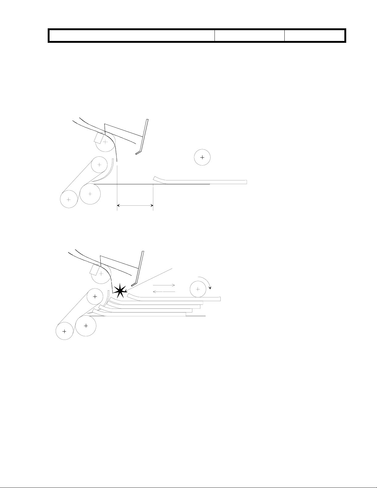
If the curl is larger than 15 mm, and the returning distance (see Fig. 10) is too long or too
short, the paper guide does not work. Thus, duplex jams may occur.
In this case, SP1-9-2 (Positioning roller on) should be adjusted so that the paper is
stacked as shown in Fig. 2.
Adjustment Standard for the returning distance: 10 - 30mm
Fig. 10
Returning distance
Fig. 11
Patterns 3 and 4
Hits
incoming
paper
Pattern 3: If the returning distance is
too long, the paper guide is raised
by the next sheet at the same time
as the positioning roller delivers the
paper. So, the paper guide cannot
work as a guide, and stack failure
occurs.
Pattern 4: If the returning distance is
too short, the paper guide is still at
the upper position when the
positioning roller delivers the paper.
So, the paper guide cannot work as
a guide, and stack failure occurs.
Page 7

RICOH Technical
Bulletin
PAGE: 7/7
Model:
Measuring the returning distance
1) Raise the positioning roller by securing the positioning roller bracket with tape so that
2) Feed and stack one sheet of the paper of the normally used size and brand into the
3) Open the front door and pull out the duplex unit gently.
4) Measure the length of the returning distance as shown in Fig. 10.
Adjusting the returning distance with SP1-9-2
1) Access SP mode and change the value of SP1-9-2 (Positioning Roller On).
If the returning distance is too long, decrease the value.
If the returning distance is too short, increase the value. (5 ms/step)
- key: The positioning roller starts earlier, + key: The positioning roller starts later.
The factory setting for SP1-9-2
50/60 cpm machines: 0
70 cpm machines: 8 (Also, SP1-17-1 No.10: 1)
Penguin (Little, Crest, Emperor)
the positioning roller does not drop.
duplex tray.
Date:
30-Nov-98
SP1-17-1 No10: 0 to 1
No.: 1
Note for 70 cpm machines
We found that curled paper in the 70 cpm machines may push the paper guide more
strongly than in 50/60 cpm machines, then the paper guide may bounce back more. This
may cause stack failure. We found that the shorter distance betw een 2 sheets o f paper
may cause returning paper to hit the paper guide. To correct this, we found the best
stacking speed for 70 cpm machines. As a temporary solution, the best stacking speed is
applied to the production machines by setting the SP1-9-2 and SP1-17-1, until a
permanent solution is implemented.
Note:
If RAM clear is done accidentally, this SP value will go to "Zero".
Page 8

RICOH Technical
Bulletin
PAGE: 1/2
Model:
Subject:
From:
Classification:
We found that curled paper in the 70-cpm machines may push the paper guide more
strongly than in 50/60 cpm machines, and then the paper guide may bounce back more.
This may cause stacking failure. (Refer to RTB No. 001 for details). As the final solution,
the production machines have been modified as follows:
1. A stopper [A] has been extended to the front of the inverter plate. (There is already a
stopper on the rear side.)
2. A cutout [B] has been made in the inverter guide to prevent the stopper [A] from striking
it.
Old P/N New P/N Description Page Index Interchang
Penguin
Inverter Guide Plate & Inverter Pla te - Ass 'y
GTSS Field Information Dept.
Troubleshooting
Mechanical
Paper path
Other ( )
Part information
Electrical
Transmit/receive
Date:
31-Jan-99
Prepared by:
No.:
2
H. Kobayashi
Action required
Service manual revision
Retrofit information
eability
A2474433 A2484433 Inverter Guide Plate 93 10 X/X
A2474442 A2484442 Inverter Plate - Ass'y 93 14 X/X
Inverter
Guide Plate B
This modification is applied to the 70-cpm version machines. To ensure good paper
stacking for 50/60-cpm version machines and to standardize the parts with 70-cpm
machines, the same modification has been applied to the 50/60-cpm version machines.
Note:
We will inform you of the cut-in serial numbers by an MB as soon as they are available.
When the old inverter guide plate or inverter plate should be replaced in the field,
replace both parts together.
A
Inverter
Plate-Ass’y
Page 9
RICOH Technical
Bulletin
PAGE: 2/2
Model:
Due to the modification on the previous page, the best stacking speed for 70-cpm
machines has been changed. Therefore, the settings of SP1-9-2 and SP1-17-1 have been
changed as follows.
The factory setting for SP1-9-2
50/60 cpm machines: 0 (no change)
70 cpm machines: -6 from 8 (Also, SP1-17-1 No.10: 0 from 1)
Penguin
Date:
31-Jan-99
No.:
2
SP1-17-1 No.10:0 from 1
Note for 70 cpm machines
The old best stacking speed for 70-cpm machines is suitable for paper stacking. Even if
the new parts are installed without changing the setting of the SP mode, a stacking failure
does not occur.
If RAM clear is done accidentally, this SP data will go to "Zero". Please note this.
Page 10

RICOH Technical
Bulletin
PAGE: 1/3
Model:
Subject:
From:
Classification:
Penguin (for North America)
DC Harmess Short-Circuit (SC104, SC105)
GTSS Field Information Dept.
Troubleshooting
Mechanical
Paper path
Other ( )
Part information
Electrical
Transmit/receive
Date:
16-Feb-99
Prepared by:
No.:
3
F. Noguchi
Action required
Service manual revision
Retrofit information
SYMPTOM
SC104 or SC105 as a result of damage to the branch harness.
The main board may also be damaged, preventing the exposure lamp from lighting or the
registration roller motor from energizing.
CAUSE
DC main harness short-circuit caused by contact between the harness and the by-pass
feed motor rotor. This occurs because the wiring harness was routed too close to the bypass feed motor.
Rotor
Point of
Contact
Branch harness that connects
to the main board
SOLUTION
Re-tape the part of the harness that shorted-out with insulation tape.
Page 11

RICOH Technical
Bulletin
PAGE: 2/3
Model:
Penguin (for North America)
Date:
16-Feb-99
No.:
3
FIELD ACTION
At installation or customer visit, please change the routing of the branch harness.
Note: The occurrence rate for this problem is extremely low but a short-circuit may lead to
damage to the main board so please take the recommended action.
The machines targeted are the ones from the first production run until the end of January.
A246-15 2B68500001 ~ 2B69410140
2B69420001, -003, -009, -013, -016~036
A246-17 A7968500001 ~ A7969410246
A7969420083, -092~223
A247-15 2B78500001 ~ 2B79410080
A247-17 A7978500001 ~ A7979410060
A248-15 2B88510001 ~ 2B89410065
A248-17 A7988500001 ~ A798852060
A7989410002, -004, -006, -009, -011, -013, -019~023, -029, -041, -044, 049, -050
1. Disconnect CN102 & CN103 on the main board.
2. Route the branch harness that connects to CN102 & CN103 so that it passes under the
main harness before connecting it to the main board. Then reconnect CN102 &
CN103.
Branch
Harness
Rotor
Main harness
Page 12

RICOH Technical
Bulletin
PAGE: 3/3
Model:
Penguin (for North America)
Date:
16-Feb-99
No.:
3
COUNTERMEASURE
The routing of the branch harness has been changed at the factory from February 9th,
1999. The cut-in serial numbers are as follows.
A246-10: Will be implemented from the 1st production run
A246-15: 2B69420037~
A246-17: A7969420224~
A247-10: Will be implemented from the 1st production run
A247-15: 2B79420001~
A247-17: A7979420001~
A248-10: Will be implemented from the 1st production run
A248-15: 2B89420001~
A248-17: A7989420001~
Page 13

RICOH Technical
Bulletin
PAGE: 1/1
Model:
Subject:
From:
Classification:
Injury may occur due to the sharp edges on the Entrance Guide Plate (A902-5561), so at
installation please take the following measures.
File off the sharp edges on the Entrance Guide Plate.
•
When filing off the sharp edges, please be careful.
•
Countermeasure
Starting from the February 25 production run, the sharp edges on the Entrance Guide
Plate will be filed off. (Please note that the Sorter Adapter does not have a serial number
so no cut-in serial number information will be available.)
Penguin
Adapter Type L: Sharp Edges
GTSS Field Information Dept.
Troubleshooting
Mechanical
Paper path
Other (Caution to taken at installation)
Part information
Electrical
Transmit/receive
Date:
28-Feb-99
Prepared by:
No.:
4
F. Noguchi
Action required
Service manual revision
Retrofit information
Entrance Guide Plate
Sharp Edges
Mounting Plate
Page 14

T
echnical
ulletin
B
PAGE: 1/2
Model:
Subject:
From:
Classification:
We have found a mistake in the service manual on page 3-49 (3.10 TRANSPORTATION
REMARKS). Please add a new step (carrying out SP2-2-2: Toner Collection Mode) before
the 1st step for the Toner Recycling Tube Cleaning procedure in your service manual as
follows:
Penguin
Transportation Remarks
GTSS Field Information Dept.
Troubleshooting
Mechanical
Paper path
Other ( )
Part information
Electrical
Transmit/receive
Date:
31-Mar-99
Prepared by:
No.:
5
H. K.
Action required
Service manual revision
Retrofit information
3.10 TRANSPORTATION REMARKS
3.10.1 TONER RECYCLING TUBE CLEANING
NOTE:
1) When transporting the machine, perform the following operations.
Otherwise the path of toner may be blocked.
2) When installing a new machine or transporting the machine which has
copied less than 1,000-sheets, these actions are not necessary.
3) Be careful not to drop the toner on the floor.
•Access SP mode and carry out SP2-2-2 (Toner Collection Mode). After the toner
collection motor stops turning, exit SP mode. Then, follow the same procedure as
described in the service manual as follows:
1. Turn off the main switch.
2. Remove the lower right cover. (Refer to Lower Right Cover Removal, section
6.1.4.)
3. While unhooking the tube clip [A] disconnect the end of tube [B], as shown.
4. While putting the end of the tube into a plastic bag, unhook the tube (1 clamp)
and set it vertically.
5. Tap the tube to remove the toner, as shown.
6. Reinstall the tube.
A
→
B
Page 15

T
echnical
B
ulletin
PAGE: 2/2
Model:
Reason for adding the new step:
The toner in the transport coil [A] may drop into the ball area [B] in the filtering unit due to
vibration during machine transportation. Then this toner may block the path of toner
coming down from the transport coil.
Penguin
A
Date:
31-Mar-99
No.:
5
B
Page 16

T
echnical
ulletin
B
PAGE: 1/1
Model:
Subject:
From:
Classification:
To enable the installation of the ST29 sorter stapler on the Penguin (Little: 50 cpm), the
following items have been changed from the June 1998 production runs.
Note: For the units manufactured in May 1998 and earlier, please add the film and install
the modified ROM.
1. With some types of recycled paper, jams may occur in the bin’s end fence. To prevent
this, film (A8342145) has been attached to the anti-static brush as shown.
2. When the duplex sorter enable by-pass mode is selected with SP mode, the jogger will
be moved even when feeding small size (A5, HLT, B6 Lengthwise) paper and the jogger
may crash into the bin. To prevent this, the software has been changed so that the
jogger will not be moved for small paper sizes. (ROM A6585103B → C)
Penguin
Installation of ST29 for the Penguin (Little: 50 cpm)
Technical Service Dept., GTS Division
Troubleshooting
Mechanical
Paper path
Other ( )
Part information
Electrical
Transmit/receive
Date:
30-Apr-99
Prepared by:
No.:
RA246006
F. Noguchi
Action required
Service manual revision
Retrofit information
Cut-in Serial Numbers
(from June ’98 production)
A658 -15:8A98060001~
-17:A7508060001~
-22:AL88060001~
-26:3N90680001~
Anti-staticBrush:A5552161
Parts Catalog Page 6
Film:A8342145
122±1 mm
0 – 1mm
Page 17
RICOH Technical
Bulletin
PAGE: 1/2
Model:
Subject:
From:
Classification:
Penguin
SC940
Technical Services Dept., GTS Division
Troubleshooting
Mechanical
Paper path
Other ( )
Date:
Prepared by:
Part information
Electrical
Transmit/receive
30-Nov-99
Action required
Service manual revision
Retrofit information
No.:
F.Noguchi
RA246007
SYMPTOM
SC940 will occur when the proper time is reached in Energy Star Auto Off mode
(default = 90 min).
CAUSE
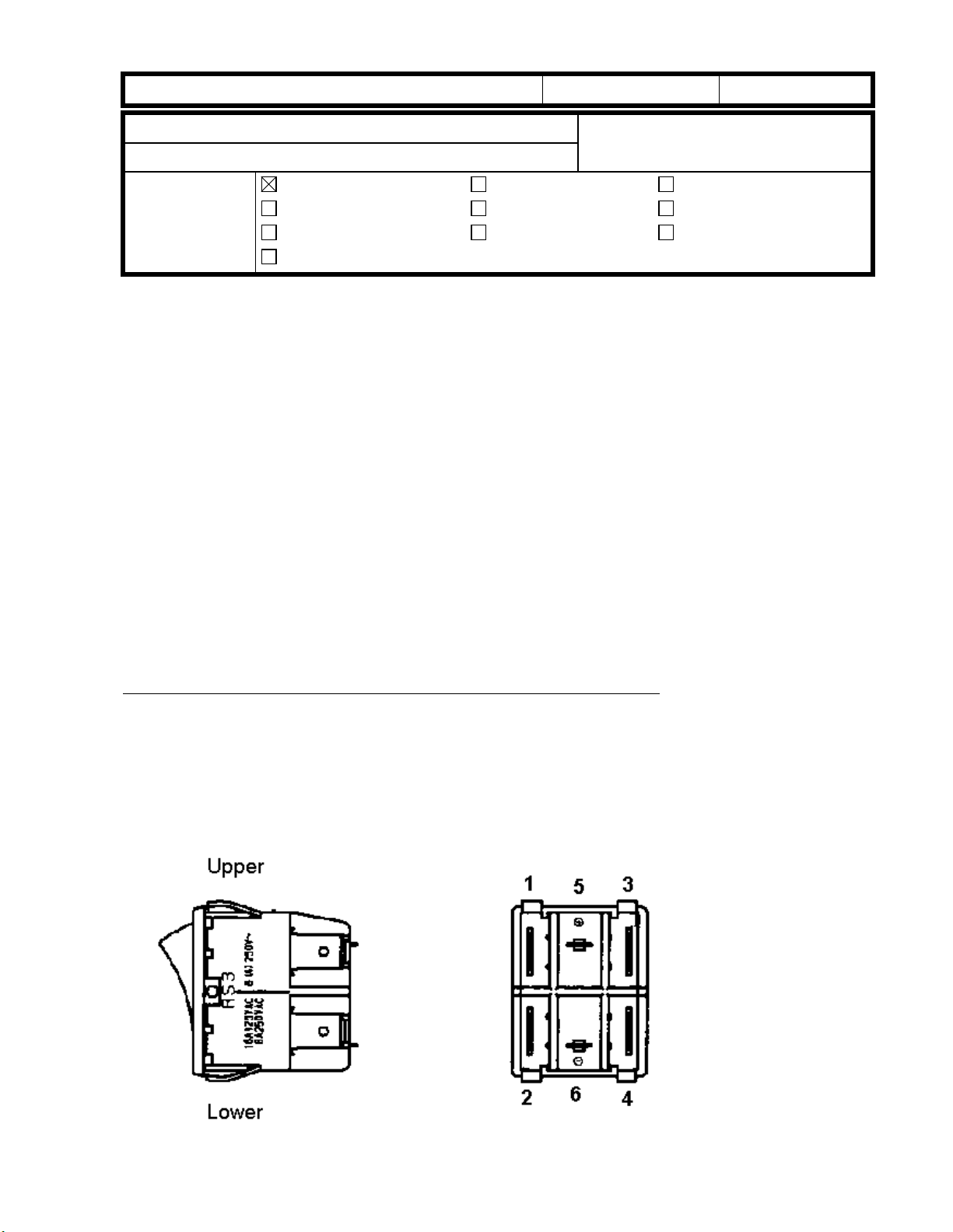
Incorrect attachment of the main switch harness DC 24V lines.
When the CN No.5 and 6 lines are reversed, the main switc h is not turned off by the Auto
Off Mode.
SOLUTION
Connect the CN No.5 and 6 lines correctly.
The following are the correct settings (please note CN no. 5 and 6):
Main SW CN No. Color of CN Color of the cable
1 yellow white
2 yellow white
3 white black
4 white black
5 white white (white)
6 white black (blue)
Page 18

RICOH Technical
Bulletin
PAGE: 2/2
Model:
Penguin
Date:
30-Nov-99
No.:
RA246007
FIELD ACTION
At installation or the next customer visit, please check the main switch harness DC 24V
lines.
Range of machines:
* It is not possible to specify the exact serial number range of machines containing the
harnesses.
A246-66: From 3R52490001 to 3R53190005
-67: From A7969240001 to A7969310021
A247-66: From 3R62490001 to 3R63090001
-67: From A7979240001 to A7979310005
COUNTERMEASURE
The error in cable connection has been acknowledged by the factory and all steps have
been taken to prevent future cases.
All production runs after November 10th,1999 contain harnesses with correct connections.
Cut-in serial Numbers:
A246-62: No Production
-66: From 3R53190006
-67: From A7969310022
A247-62: No Production
-66: From 3R63190001
-67: From A7979310006
 Loading...