

Page 1

Penguin Series
Little/Crest/Emperor
(Machine Code: A246/A247/ A248)
Service Manual
Page 2

TABLE OF CONTENTS
IMPORTANT SAFETY NOTICES
1. OVERALL MACHINE INFORMATION 1-1..........................
1.1 SPECIFICATION 1-1......................................................
1.2 MACHINE CONFIGURATION 1-6..................................
1.2.1 COPIER OVERVIEW 1-6.....................................................
1.2.2 SYSTEM OVERVIEW 1-6....................................................
1.3 COPY PROCESS AROUND THE DURM 1-8................
1.4 MECHANICAL COMPONENT LAYOUT 1-10..................
1.5 DRIVE LAYOUT 1-12.......................................................
1.6 PAPER PATH 1-13...........................................................
1.6.1 STANDARD COPYING 1-13.................................................
1.6.2 MULTIPLE 2-SIDE COPYING 1-14.......................................
1.7 ELECTRICAL COMPONENT DESCRIPTION 1-15.........
2. DETAILED SECTION DESCRIPTIONS 2-1........................
2.1 PROCESS CONTROL 2-1..............................................
2.1.1 OVERVIEW 2-1...................................................................
2.1.2 PROCESS CONTROL DATA INITIAL SETTING 2-4..........
2.1.3 LATENT IMAGE CONTROL 2-5..........................................
2.1.4 IMAGE DENSITY CONTROL 2-12........................................
2.2 DRUM UNIT 2-18..............................................................
2.2.1 OVERVIEW 2-18...................................................................
2.2.2 OPC DRUM CHARACTERISTICS 2-19................................
2.2.3 DRUM CHARGE 2-20............................................................
2.2.4 ERASE 2-23...........................................................................
2.2.5 CLEANING 2-25....................................................................
2.2.6 QUENCHING 2-30.................................................................
2.3 DRUM CLEANING AND TONER-RECYCLING 2-31.......
2.3.1 TONER TRANSPORT 2-31...................................................
2.3.2 FILTERING 2-32....................................................................
2.3.3 PUMP MECHANISM 2-33.....................................................
2.3.4 DRIVE MECHANISM 2-34.....................................................
2.3.5 TONER COLLECTION BOTTLE 2-35...................................
2.4 OPTICS 2-36....................................................................
2.4.1 OVERVIEW 2-36...................................................................
2.4.2 SCANNER DRIVE 2-37.........................................................
2.4.3 VERTICAL LENS DRIVE 2-38...............................................
2.4.4 HORIZONTAL LENS DRIVE 2-39.........................................
2.4.5 HORIZONTAL LENS POSITIONING 2-40.............................
2.4.6 3 SCANNER DRIVE 2-42......................................................
2.4.7 OPTICS CONTROL CIRCUIT 2-43.......................................
2.4.8 AUTOMATIC IMAGE DENSITY CONTROL 2-44..................
2.4.9 MANUAL IMAGE DENSITY CONTROL 2-46........................
2.4.10 UNEVEN LIGHT INTENSITY CORRECTION 2-47.............
Page 3

2.4.11 ORIGINAL SIZE DETECTION IN PLATEN MODE 2-48......
2.4.12 HALF TONE MODE 2-50.....................................................
2.5 DEVELOPMENT 2-51.......................................................
2.5.1 OVERVIEW 2-51...................................................................
2.5.2 DEVELOPMENT MECHANISM 2-52.....................................
2.5.3 DRIVE MECHANISM 2-53.....................................................
2.5.4 CROSSMIXING 2-54.............................................................
2.5.5 DEVELOPMENT BIAS 2-55..................................................
2.5.6 TONER SUPPLY 2-60...........................................................
2.6 IMAGE TRANSFER 2-64..................................................
2.6.1 PRE-TRANSFER LAMP 2-64................................................
2.6.2 IMAGE TRANSFER AND PAPER SEPARATION 2-65.........
2.6.3 IMAGE TRANSFER AND PAPER SEPARATION 2-66.........
2.6.4 TRANSFER BELT UNIT LIFT MECHANISM 2-68.................
2.6.5 PAPER TRANSPORTATION AND BELT DRIVE 2-69..........
2.6.6 TRANSFER BELT CLEANING MECHANISM 2-70...............
2.6.7 TONER COLLECTION MECHANISM 2-71...........................
2.6.8 TRANSFER ANTI-CONDENSATION HEATER 2-72.............
2.7 PAPER FEED 2-73...........................................................
2.7.1 OVERVIEW 2-73...................................................................
2.7.2 FRR FEED SYSTEM 2-74.....................................................
2.7.3 SLIP CLUTCH MECHANISM 2-76........................................
2.7.4 FRR FEED DRIVE MECHANISM 2-77..................................
2.7.5 SEPARATION ROLLER RELEASE MECHANISM 2-79........
2.7.6 PAPER RETURN MECHANISM 2-80....................................
2.7.7 PAPER SKEW PREVENTION MECHANISM 2-81................
2.7.8 PAPER LIFT MECHANISM 2-82...........................................
2.7.9 PAPER NEAR END/PAPER END DETECTION 2-85............
2.7.10 TANDEM FEED TRAY 2-86................................................
2.7.11 PAPER SIZE DETECTION 2-90..........................................
2.7.12 VERTICAL TRANSPORT MECHANISM 2-91.....................
2.7.13 TRAY POSITIONING MECHANISM 2-92............................
2.7.14 BY-PASS FEED TABLE 2-95..............................................
2.7.15 PAPER REGISTRATION 2-98.............................................
2.7.16 REGISTRATION DRIVE MECHANISM 2-99.......................
2.7.17 GUIDE PLATE RELEASE MECHANISM 2-100....................
2.8 IMAGE FUSING 2-101........................................................
2.8.1 OVERVIEW 2-101...................................................................
2.8.2 FUSING ENTRANCE GUIDE 2-102........................................
2.8.3 FUSING DRIVE MECHANISM 2-103......................................
2.8.4 FUSING LAMP CONTROL 2-104............................................
2.8.5 INVERTER AND PAPER EXIT 2-105......................................
2.8.6 INVERTER AND EXIT DRIVE MECHANISM 2-106................
2.9 DUPLEX 2-107...................................................................
2.9.1 OVERVIEW 2-107...................................................................
2.9.2 DRIVE MECHANISM 2-108.....................................................
2.9.3 DUPLEX ENTRANCE TO DUPLEX TRAY 2-109....................
2.9.4 DUPLEX STACKING 2-110.....................................................
2.9.5 DUPLEX PICK-UP ROLLER MECHANISM 2-111..................
Page 4

2.9.6 DUPLEX PAPER FEED 2-112.................................................
2.10 ENERGY STAR COMPLIANT MACHINES (ALL 2-115....
2.11 ENERGY SAVING INFORMATION 2-117........................
2.11.1 ABOUT THE ENERGY SAVING FEATURES OF 2-117.......
3. INSTALLATION PROCEDURE 3-1......................................
3.1 INSTALLATION REQUIREMENTS 3-1..........................
3.1.1 ENVIRONMENT 3-1............................................................
3.1.2 MACHINE LEVEL 3-1..........................................................
3.1.3 MINIMUM SPACE REQUIREMENTS 3-2...........................
3.1.4 POWER REQUIREMENTS 3-2...........................................
3.2 COPIER (A246/A247/A248) 3-3.....................................
3.2.1 ACCESSORY CHECK 3-3...................................................
3.2.2 INSTALLATION PROCEDURE 3-4.....................................
3.2.3 GUIDANCE ROM INSTALLATION (OPTION: 3-14...............
3.2.4 PLATEN COVER (OPTION) INSTALLATION 3-15...............
3.2.5 KEY COUNTER HOLDER INSTALLATION 3-16..................
3.2.6 ORIGINAL TRAY INSTALLATION (OPTION) 3-18...............
3.3 UNIVERSAL TRAY (TRAY 2) 3-19..................................
3.4 550 SHEETS PAPER TRAY (TRAY 3) 3-20....................
3.5 TANDEM FEED TRAY PAPER SIZE CHANGE 3-22......
3.6 DUAL JOB FEEDER (A610) 3-25....................................
3.6.1 ACCESSORY CHECK 3-25...................................................
3.6.2 INSTALLATION PROCEDURE 3-26.....................................
3.7 SORTER STAPLER (A821) 3-29.....................................
3.7.1 ACCESSORY CHECK 3-29...................................................
3.7.2 INSTALLATION PROCEDURE 3-30.....................................
3.7.3 SORTER ADAPTER INSTALLATION (OPTION) 3-34..........
3.8 20 BIN SORTER STAPLER (A658) (A246 ONLY) 3-36..
3.8.1 ACCESSORY CHECK 3-36...................................................
3.8.2 INSTALLATION PROCEDURE 3-37.....................................
3.9 LCT (A822) 3-41...............................................................
3.9.1 ACCESSORY CHECK 3-41...................................................
3.9.2 INSTALLATION PROCEDURE 3-42.....................................
3.9.3 PAPER SIZE CHANGE 3-46.................................................
3.10 TRANSPORTATION REMARKS 3-49............................
3.10.1 TONER RECYCLING TUBE CLEANING 3-49....................
3.10.2 OTHER OPERATIONS 3-49................................................
4. SERVICE TABLES 4-1.........................................................
4.1 GENERAL CAUTIONS 4-1.............................................
4.1.1 DRUM 4-1............................................................................
4.1.2 DRUM UNIT 4-1...................................................................
4.1.3 CHARGE CORONA 4-2......................................................
4.1.4 OPTICS 4-2.........................................................................
4.1.5 ERASE LAMP 4-3................................................................
4.1.6 DEVELOPMENT UNIT 4-3..................................................
4.1.7 TRANSFER BELT UNIT 4-3................................................
Page 5

4.1.8 CLEANING SECTION 4-4...................................................
4.1.9 PRE-TRANSFER LAMP 4-4................................................
4.1.10 PAPER FEED 4-4..............................................................
4.1.11 FUSING UNIT 4-4..............................................................
4.1.12 USED TONER 4-5.............................................................
4.2 SERVICE PROGRAM MODE 4-6..................................
4.2.1 SERVICE PROGRAM MODE OPERATION 4-6.................
4.2.2 SERVICE PROGRAM MODE TABLES 4-8.........................
4.2.3 INPUT CHECK 4-45..............................................................
4.2.4 OUTPUT CHECK 4-48..........................................................
4.3 USER PROGRAM 4-51....................................................
4.3.1 HOW TO ENTER AND EXIT UP MODE 4-51.......................
4.3.2 UP MODE TABLE 4-51..........................................................
4.4 TEST POINTS/DIP SWITCHES/LEDS 4-53....................
4.4.1 DIP SWITCHES 4-53.............................................................
4.4.2 TEST POINTS 4-53...............................................................
4.4.3 FUSES 4-54...........................................................................
4.4.4 LEDS 4-54.............................................................................
4.5 SPECIAL TOOLS AND LUBRICANTS 4-54.....................
4.5.1 SPECIAL TOOLS 4-54..........................................................
4.5.2 LUBRICANTS 4-54................................................................
4.6 TOUCH PANEL DISPLAY POSITION 4-55.....................
5. PREVENTIVE MAINTENANCE SCHEDULE 5-1................
5.1 PM TABLE 5-1................................................................
5.2 PM PROCEDURE 5-5....................................................
5.2.1 CLEARING PM COUNTER 5-5...........................................
5.2.2 PM PROCEDURE 5-6.........................................................
6. REPLACEMENT AND ADJUSTMENT 6-1.........................
6.1 EXTERIOR AND INNER COVER REMOVAL 6-1.........
6.1.1 FRONT COVER 6-1.............................................................
6.1.2 REAR SIDE 6-2...................................................................
6.1.3 INNER COVER 6-3..............................................................
6.1.4 RIGHT SIDE 6-6..................................................................
6.1.5 LEFT SIDE 6-7.....................................................................
6.1.6 OPERATION PANEL 6-8.....................................................
6.1.7 UPPER COVER 6-9.............................................................
6.2 PAPER FEED 6-10...........................................................
6.2.1 PAPER TRAY UNIT REMOVAL 6-10....................................
6.2.2 PAPER TRAY REMOVAL 6-13.............................................
6.2.3 PAPER FEED ROLLERS REPLACEMENT 6-16..................
6.2.4 PAPER FEED TIMING ADJUSTMENT 6-17.........................
6.2.5 PAPER FEED CLUTCH REMOVAL (1ST TRAY 6-20...........
6.2.6 REAR FENCE RETURN SENSOR REPLACEMENT 6-24....
6.2.7 REAR FENCE HP SENSOR REPLACEMENT 6-25..............
6.2.8 BOTTOM PAPER SENSOR REPLACEMENT 6-26..............
6.2.9 BY-PASS FEED TABLE REMOVAL 6-27..............................
Page 6

6.2.10 BY-PASS FEED ROLLERS REPLACEMENT 6-28.............
6.2.11 BY-PASS PAPER SIZE SENSOR REPLACEMENT 6-29...
6.2.12 BY-PASS FEED CLUTCH AND GUIDE PLATE 6-31..........
6.2.13 REGISTRATION MOTOR REMOVAL 6-33.........................
6.2.14 PAPER DUST CLEANER CLEANING 6-34........................
6.2.15 REGISTRATION SENSOR CLEANING 6-35......................
6.2.16 UNIVERSAL TRAY SIZE SWITCH REPLACEMEN 6-36....
6.2.17 550-SHEET TRAY SET SWITCH REPLACEMENT 6-37....
6.2.18 LIFT MOTOR REMOVAL 6-38............................................
6.2.19 PAPER FEED MOTOR REMOVAL 6-39.............................
6.2.20 COPIER FEED UNIT REMOVAL 6-40................................
6.2.21 BOTTOM PLATE LIFT WIRE REPLACEMENT 6-42..........
6.2.22 550 SHEETS PAPER TRAY (TRAY 3) 6-44........................
6.2.23 TANDEM FEED TRAY PAPER SIZE CHANGE 6-46..........
6.3 OPTICS 6-49....................................................................
6.3.1 EXPOSURE GLASS REMOVAL 6-49...................................
6.3.2 EXPOSURE LAMP REPLACEMENT 6-50............................
6.3.3 OPTICS THERMOSWITCH REPLACEMENT 6-52...............
6.3.4 SCANNER HP SENSOR REPLACEMENT 6-53...................
6.3.5 ADS SENSOR REMOVAL 6-54.............................................
6.3.6 SCANNER DRIVE MOTOR 6-55...........................................
6.3.7 SCANNER DRIVE WIRES REPLACEMENT 6-56.................
6.3.8 THIRD SCANNER REMOVAL 6-72.......................................
6.3.9 THIRD SCANNER DRIVE MOTOR/HP SENSOR 6-73.........
6.3.10 LENS HORIZONTAL DRIVE HP SENSOR 6-75.................
6.3.11 LENS HORIZONTAL DRIVE MOTOR 6-77.........................
6.3.12 APS SENSOR ADJUSTMENT (SENSITIVITY 6-79...........
6.3.13 ARS SENSOR ADJUSTMENT 6-80....................................
6.4 TONER RECYCLING 6-81...............................................
6.4.1 TONER RECYCLING UNIT REMOVAL 6-81........................
6.4.2 TONER RECYCLING CLUTCH REPLACEMENT 6-82.........
6.5 DEVELOPMENT AND TONER SUPPLY 6-83................
6.5.1 DEVELOPMENT UNIT REMOVAL 6-83................................
6.5.2 DEVELOPER REPLACEMENT 6-85.....................................
6.5.3 DEVELOPMENT ROLLERS REPLACEMENT 6-87..............
6.5.4 TONER DENSITY SENSOR REPLACEMENT 6-89..............
6.5.5 TONER BOTTLE DRIVE MOTOR REPLACEMENT 6-90.....
6.5.6 DEVELOPMENT FILTER AND PRESSURE 6-91.................
6.5.7 DEVELOPMENT ROLLER SHAFT CLEANING 6-92............
6.6 DRUM UNIT 6-93..............................................................
6.6.1 DRUM UNIT REMOVAL AND OPC DRUM 6-93...................
6.6.2 QUENCHING LAMP REPLACEMENT 6-94..........................
6.6.3 GRID PLATE/CHARGE WIRE/WIRE CLEANER 6-95.........
6.6.4 ERASE LAMP AND DRUM POTENTIAL SENSOR 6-97......
6.6.5 CLEANING BLADE REPLACEMENT 6-98............................
6.6.6 CLEANING BRUSH REPLACEMENT 6-99...........................
6.6.7 PICK-OFF PAWL REPLACEMENT 6-100...............................
6.6.8 OZONE FILTER REPLACEMENT 6-101.................................
6.6.9 PRE-TRANSFER LAMP REMOVAL 6-102.............................
Page 7

6.7 TRANSFER BELT UNIT 6-103..........................................
6.7.1 TRANSFER BELT UNIT REMOVAL/INSTALLATION 6-103...
6.7.2 TRANSFER BELT REPLACEMENT 6-105.............................
6.7.3 CLEANING BLADE REPLACEMENT 6-107............................
6.8 FUSING UNIT 6-108...........................................................
6.8.1 FUSING UNIT REMOVAL 6-108.............................................
6.8.2 FUSING THERMISTOR REPLACEMENT 6-109.....................
6.8.3 FUSING THERMOFUSE REPLACEMENT 6-110...................
6.8.4 FUSING LAMP REPLACEMENT 6-111..................................
6.8.5 OIL SUPPLY/CLEANING ROLLER REPLACEMENT 6-113...
6.8.6 OIL SUPPLY CLEANING BRUSH REPLACEMENT 6-114.....
6.8.7 HOT ROLLER REPLACEMENT 6-115....................................
6.8.8 PRESSURE ROLLER AND BEARING 6-117..........................
6.8.9 FUSING STRIPPER PAWL REPLACEMENT 6-119...............
6.8.10 FUSING PRESSURE ADJUSTMENT 6-120.........................
6.8.11 PAPER EXIT UNIT REMOVAL 6-121....................................
6.8.12 EXIT SENSOR AND FUSING EXIT SENSOR 6-123............
6.8.13 DUPLEX PAPER GUIDE SENSOR AND 6-124....................
6.8.14 PRESSURE ROLLER CLEANING ROLLER 6-125...............
6.9 DUPLEX UNIT 6-126..........................................................
6.9.1 FEED ROLLER REPLACEMENT 6-126..................................
6.9.2 SEPARATION BELT REPLACEMENT 6-128..........................
6.9.3 DUPLEX UNIT REMOVAL 6-131............................................
6.9.4 SEPARATION CLUTCH/TRANSPORT CLUTCH 6-132.........
6.9.5 JOGGER MOTOR REPLACEMENT 6-133.............................
6.10 COPY QUALITY ADJUSTMENT 6-138............................
6.10.1 SP ADJUSTMENT MODE 6-138...........................................
6.10.2 SIDE-TO-SIDE REGISTRATION ADJUSTMENT 6-140........
6.10.3 UNEVEN EXPOSURE ADJUSTMENT 6-141........................
6.10.4 IMAGE DENSITY ADJUSTMENT 6-143...............................
6.10.5 SCANNER HEIGHT ADJUSTMENT 6-144...........................
6.10.6 APS SIZE CALIBRATION 6-145............................................
6.10.7 FUSING EXIT COVER MAGNET POSITIONING 6-146.......
7. TROUBLESHOOTING 7-1...................................................
7.1 SERVICE CALL CONDITIONS 7-1...............................
7.1.1 SUMMARY 7-1....................................................................
7.1.2 EXPOSURE 7-3...................................................................
7.1.3 SCANNER 7-5.....................................................................
7.1.4 LENS MAGNIFICATION 7-8................................................
7.1.5 OPTICS THERMISTOR 7-10.................................................
7.1.6 CHARGE CORONA UNIT 7-10.............................................
7.1.7 DEVELOPMENT 7-11............................................................
7.1.8 PROCESS CONTROL SENSORS 7-12................................
7.1.9 TRANSFER CURRENT 7-15.................................................
7.1.10 DRUM 7-15..........................................................................
7.1.11 PAPER FEED 7-16..............................................................
7.1.12 DUPLEX 7-19......................................................................
7.1.13 FUSING 7-20.......................................................................
Page 8

7.1.14 SYSTEM CONTROL 7-22...................................................
7.1.15 DUAL JOB FEEDER 7-23....................................................
7.1.16 SORTER STAPLER 7-24....................................................
7.1.17 OTHERS 7-28......................................................................
7.2 ELECTRICAL COMPONENT DEFECTS 7-30................
7.2.1 SENSORS 7-30.....................................................................
7.2.2 SWITCHES 7-34....................................................................
7.2.3 FUSES 7-35...........................................................................
POINT TO POINT DIAGRAM & ELCTRICAL
A246/A247/A248/A822 POINT TO POINT DIAGRAM
ELECTRICAL COMPONENT LAYOUT (A246/ A247/ A248
ELECTRICAL COMPONENT LAYOUT (A246/ A247/ A248
SORTER STAPLER (A821)
ELECTRICAL COMPONENT LAYOUT (A821)
Page 9

IMPORTANT SAFETY NOTICES
PREVENTION OF PHYSICAL INJURY
1. Before disassembling or assembling parts of the copier and peripherals,
make sure that the copier power cord is unplugged.
2. The wall outlet should be near the copier and easily accessible.
3. Note that some components of the copier and the paper tray unit are
supplied with electrical voltage even if the main switch is turned off.
4. If any adjustment or operation check has to be made with exterior covers off
or open while the main switch is turned on, keep hands away from electrified
or mechanically driven components.
5. The inside and the metal parts of the fusing unit become extremely hot while
the copier is operating. Be careful to avoid touching those components with
your bare hands.
6. The copier is not attached to the table. Pushing the copier too heard may
cause it to drop onto the floor. While moving the copier, push the table.
7. When the main switch is tuned on, the machine will suddenly start turning to
perform the developer initialization. Keep hand away from any mechanical
and electrical components during this per iod.
HEALTH SAFETY CONDITIONS
1. Never operate the copier without the ozone filters installed.
2. Always replace the ozone filters with the specified ones at the specified
intervals.
3. Toner and developer are non-toxic, but if you get either of them in your eyes
by accident, it may cause temporary eye discomfort. Try to remove with eye
drops or flush with water as first aid. If unsuccessful, get medical attention.
OBSERVANCE OF ELECTRICAL SAFETY STANDARDS
1. The copier and its peripherals must be installed and maintained by a
customer service representative who has completed the training course on
those models.
CAUTION:
The RAM board on the main control boar d has a li thi u m batt er y
which can explode if replaced incorrectly. Replace the RAM board
only with an identical one. Th e man u fact urer re co m men ds re pl aci ng
the entire RAM board. Do not recharge or burn this battery. Used
RAM board must be handled in accordance with local regulations.
Page 10

SAFETY AND ECOLOGICAL NOTES FOR DISPOSAL
1. Do not incinerate the toner cartridge or the used toner. Toner dust may ignite
suddenly when exposed to open flame.
2. Dispose of used toner, developer, and organic photoconductor according to
local regulations. (These are non-toxic supplies.)
3. Dispose of replaced parts in accordance with local regulations.
4. When keeping used RAM boards in order to dispose of them later, do not put
more than 100 RAM boards per sealed box. Storing larger numbers or not
sealing them apart may lead to chemical reactions and heat build-up.
Page 11

21 September 1998 SPECIFICATION
1. OVERALL MACHINE INFORMATION
1.1 SPECIFICATION
Configuration: Console
Copy Process: Dry electrostatic transfer system
Toner Supply Control: Fuzzy Control
Photoconductor: OPC drum
Originals: Sheet/Book
Original Size: Maximum A3/11" x 17"
Original Alignment: Left rear corner
Copy Paper Size: Maximum A3/11" x 17" (Tray & By-pass)
A4/8
Minimum A5/5
A4/8
A6/5
Duplex Copying: Maximum A3/11" x 17"
Minimum A5/5
Copy Paper Weight: Paper tray: 52 ~ 128 g/m2, 14 ~ 34 lb
By-pass feed table: 52 ~ 200 g/m2, 14 ~ 53 lb
Duplex copying: 64 ~ 104 g/m2, 17 ~ 24 lb
" x 11" (Tandem LCT)
1/2
" x 8
1/2
" x 11" (Tandem LCT)
1/2
" x 8
1/2
" x 8
1/2
" (Tray)
1/2
" (By-pass)
1/2
" (Sideways)
1/2
Overall
Information
Reproduction Ratios: 4 Enlargement and 5 Reduction + Create Margin
(93%)
A4/A3 Version LT/LDG Version
200%
Enlargement
Full Size 100% 100%
Reduction
141%
122%
115%
82%
75%
71%
65%
50%
200%
155%
129%
121%
85%
77%
74%
65%
50%
1-1
Page 12

SPECIFICATION 21 September 1998
Power Source: 115 V, 60 Hz, more than 20 A (for N.A)
220 ~ 240 V, 50 Hz/60 Hz, more than 10 A (for
Europe and Asia)
Power Consumption:
- A246 copier -
Copier only Full system*
Warm up 1.20 kVA 1.22 kVA
Stand-by*
Low Power mode*
2
2
0.22 kVA 0.24 kVA
0.185 kVA 0.205 kVA
Copying 1.40 kVA 1.40 kVA
Maximum 1.70 kVA 1.75 kVA
Off-mode 0.001 kVA 0.001 kVA
- A247 copier -
Copier only Full system*
Warm up 1.20 kVA 1.22 kVA
Stand-by*
Low Power mode*
2
2
0.22 kVA 0.24 kVA
0.21 kVA 0.23 kVA
Copying 1.50 kVA 1.50 kVA
Maximum 1.70 kVA 1.75 kVA
Off-mode 0.001 kVA 0.001 kVA
- A248 copier -
Copier only Full system*
Warm up 1.20 kVA 1.22 kVA
Stand-by*
Low Power mode*
Copying 1.60 kVA 1.60 kVA
Maximum 1.70 kVA 1.75 kVA
Off-mode 0.001 kVA 0.001 kVA
2
2
0.22 kVA 0.24 kVA
0.21 kVA 0.23 kVA
1
1
1
*1Full System:
Mainframe with dual job feeder, sorter stapler
and 3,500-sheet large capacity tray
2
*
: When the anti-condensation heaters are off.
1-2
Page 13

21 September 1998 SPECIFICATION
Noise Emission: Sound Pressure Level:
The measurements are ma de accor di ng to
ISO7779
- A246 copier -
Overall
Information
Sound pressure level
Sound power level
- A247 copier -
Sound pressure level
Sound power level
(The measurements are made according to ISO 7779 at
the operator position.)
Copier only
Stand-by Less than 34 dB (A)
Copying Less than 57 dB (A) (average)
(The measurements are made according to ISO 7779.)
Copier only
Stand-by Less than 48 dB (A)
Copying Less than 71 dB (A) (average)
(The measurements are made according to ISO 7779 at
the operator position.)
Copier only
Stand-by Less than 34 dB (A)
Copying Less than 59 dB (A) (average)
(The measurements are made according to ISO 7779.)
- A248 copier -
Sound pressure level
Sound power level
Copier only
Stand-by Less than 51 dB (A)
Copying Less than 72 dB (A) (average)
(The measurements are made according to ISO 7779 at
the operator position.)
Copier only
Stand-by Less than 36 dB (A)
Copying Less than 59 dB (A) (average)
(The measurements are made according to ISO 7779.)
Copier only
Stand-by Less than 54 dB (A)
Copying Less than 73 dB (A) (average)
1-3
Page 14

SPECIFICATION 21 September 1998
Dimensions:
Width Depth Height
Copier only
Copier with dual job feeder, sorter stapler,
and 3,500-sheet large capacity tray
Copier with dual job feeder, sorter stapler with
punch, and 3,500-sheet large capacity tray
690 mm
27.2"
1,659 mm
65.4"
1,659 mm
65.4"
698 mm
27.6"
698 mm
27.6"
698 mm
27.6"
980 mm
38.6"
1,113 mm
43.9"
1,113 mm
43.9"
Weight: Copier only: (Without the optional platen cover
= Approximately 2 kg)
Approximately 175 kg
Zoom: From 50% to 200% in 1% steps
Copying Speed:
A246 copier
A247 copier 60 31 38
A248 copier 70 36 44
A4/LT (sideways) A3/DLT B4/LG
51 (A4 others)
50 (A4/in France)
50 (LT)
26 32
Warm-up Time: Less than 5 minutes (A246 copier, 20°C)
Less than 5.5 minutes (A247/A248 copier, 20°C)
First Copy Time:
(A4/5
" x 11" sideways
1/2
3.1 seconds (A246 copier)
2.6 seconds (A247/A248 copiers)
from the 1st feed station)
Copy Number Input: Number keys, 1 to 999 (count up or count down)
Manual Image Density
9 steps
Selection:
Automatic Reset: 1 minute standard setting; can also be set from 1
second to 999 seconds or no auto reset.
Copy Paper Capacity:
By-pass feed table: approximately 50 sheets
Paper tray: approximately 550 sheets
Tandem LCT tray: approximately 1,550 sheets
Toner Replacement: 1,160 g/cartridge
1-4
Page 15

21 September 1998 SPECIFICATION
Optional Equipment:
Platen cover (A528-04)
Dual job feeder (A610)
20 bin sorter stapler (Floor type) (A821-17:
Ricoh, -22: NRG, -15: Savin/Ges U.S.A. –26:
Infotec)
3,500-sheet Large capacity tray (A822)
Receiving tray (A446-05)
Key Counter Bracket D (A509-03)
20 bin sorter Stapler (Floor type) with punch
(A821-57 (3 holes), -67 (2 holes): Ricoh, -62:
NRG, -66: Infotec, -55: Savin/Ges U.S.A.)
Guidance ROM KIT Type U (A870)
Editing sheet (spare part)
Original Tray type F (A430-07)
Sorter Adapter type L (A902-19)
20 bin sorter stapler (Hunging type) (A658)
(A246 copier only)
When the 20 bi n sorter stapler (A658) is installed onto A246 copier, sorter adapter
type L is required.
Overall
Information
1-5
Page 16
MACHINE CONFIGURATION 21 September 1998
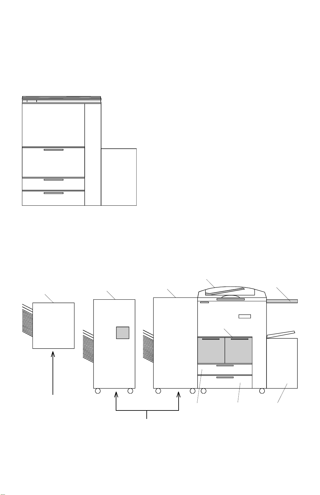
1.2 MACHINE CONFIGURATION
1.2.1 COPIER OVERVIEW
- A246/A247/A248 copiers -
Tandem LCT
(including two 1,550-sheet LCT
Two 550-sheet paper trays
Optional 3,500-sheet large capacity tray
1,550 x 2
550
550
(3,500)
A246V500.WMF
1.2.2 SYSTEM OVERVIEW
Hunging S/S
S/S with Punch
S/S
DJF
Original Tray
Tandem LCT
Hunging Sorter Stapler
(A658)
Floor type Sorter Stapler (A821-17, -15, -22, -26)
Floor type Sorter Stapler with Punch (A821-57, -67, -55, -62, -66)
1-6
Universal
Fixed
3,500 sheets
LCT
A246V501.WMF
Page 17

21 September 1998 MACHINE CONFI GURATION
MEMO
Overall
Information
1-7
Page 18
COPY PROCESS AROUND THE DURM 21 September 1998
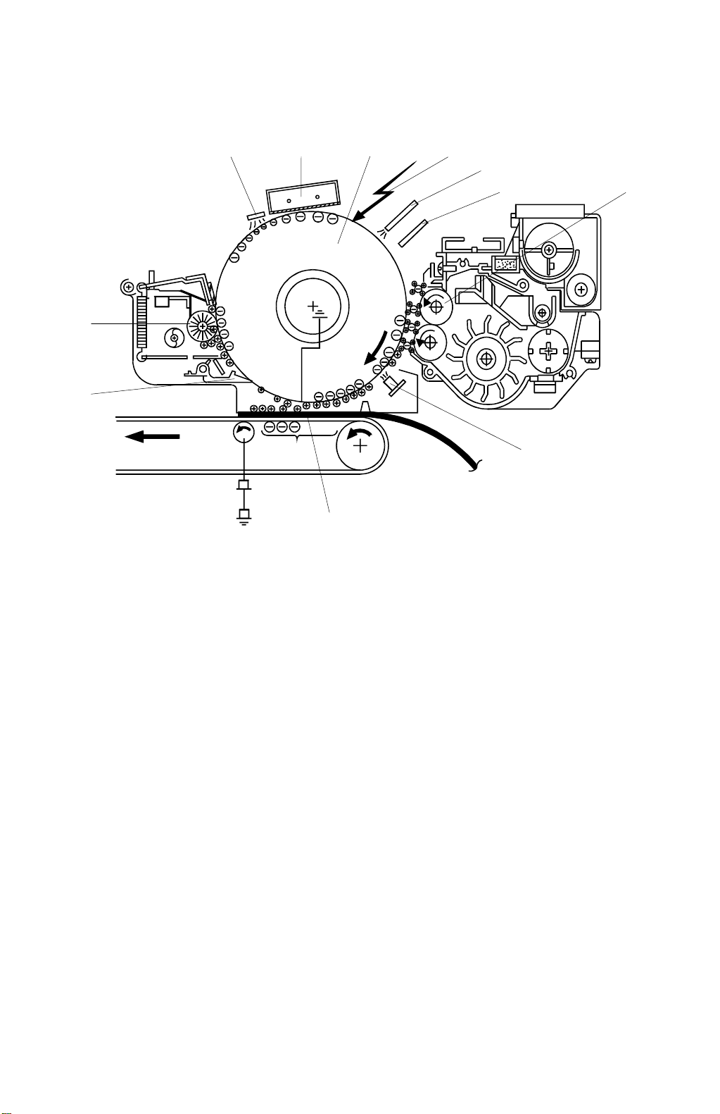
1.3 COPY PROCESS AROUND THE DURM
10
11
12
3
4
5
6
9
7
8
A246V502.WMF
1. OPC DRUM
The organic photo conductive (OPC) drum (100 mm diameter) has high resistance
in the dark and low resistance under light.
2. DRUM CHARGE
In the dark, the charge corona unit gives a uniform negative charge to the OPC
drum. The charge remains on the surface of the drum. The amount of negative
charge on the drum is proportional to the negative grid bias voltage applied to the
grid plate on the charge corona unit.
3. EXPOSURE
An image of the original is reflected to the OPC drum surface via the optics section.
The charge on the drum surface is dissipated in direct proportion to the intensity of
the reflected light, thus producing an electrical latent image on the drum surface.
The amount of charge remaining as a latent image on the drum depends on the
exposure lamp intensity controlled by the exposure lamp voltage.
4. ERASE
The erase lamp illuminates the areas of the charged drum surface that will not be
used for the copy image. The resistan ce of drum in the illuminated areas drops and
the charge on those areas dissipates.
1-8
Page 19

21 September 1998 COPY PROCESS AROUND THE DURM
5. DRUM POTENTIAL SENSOR
The drum potential sensor detects the electric potential on the drum to compensate
image processing elements.
6. DEVELOPMENT
Positively charged toner is attracted to the negatively charged areas of the drum,
thus developing the latent image. (The positive triboelectric charge of the toner is
caused by friction between the carrier and toner particles.)
The development bias voltage applied to the development roller shaft controls two
things:
1) The threshold level if toner is attracted to the drum or toner remains on the
development roller.
2) The amount of toner to be attracted to the drum.
The higher the negative development bias voltage is, the less toner is attracted to
the drum surface.
7. PRE-TRANSFER LAMP (PTL)
The PTL illuminates the drum to remove almost all the negative charge from the
exposed areas of the drum. This makes image transfer easier.
Overall
Information
8. IMAGE TRANSFER
Paper is fed to the drum surface at the proper timing so as to align the copy paper
and the developed image on the drum surface. Then, a negative charge is applied
to the reverse side of the copy paper by the transfer belt, producing an electrical
force which pulls the toner particles from the drum surface onto the copy paper. At
the same time, the copy paper is electrically attracted to the transfer belt.
9. PAPER SEPARATION
Paper separates from the OPC drum by the electrical attraction between the paper
and the transfer belt. The pick-off pawls help to separate the paper from the drum.
10. CLEANING
The cleaning brush removes toner remaining on the drum after image transfer and
the cleaning blade scrapes off all the remaining toner.
11. QUENCHING
Light from the quenching lamp electrically neutralizes the charge potential of the
drum surface.
1-9
Page 20
MECHANICAL COMPONENT LAYOUT 21 September 1998
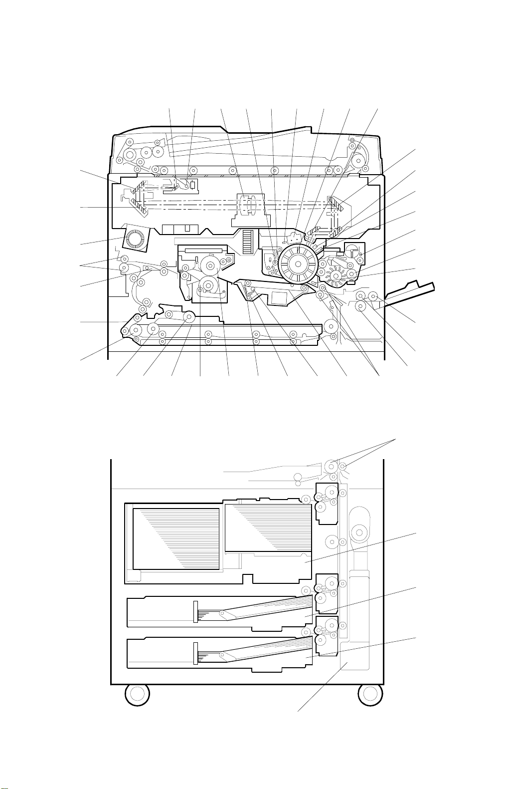
1.4 MECHANICAL COMPONENT LAYOUT
34567891011
12
39
38
37
36
35
2
13
14
1
15
16
17
18
19
20
21
34 33 32 31 30 29 41 40 2323
22
A246V503.WMF
24
1-10
28
25
26
27
A246V504.WMF
Page 21

21 September 1998 MECHANICAL COMPONENT LAYOUT
1. 3rd Mirror
2. 2nd Mirror
3. 1st Mirror
4. Exposure Lamp
5. Lens
6. Cleaning Brush
7. Cleaning Blade
8. Quenching Lamp
9. Charge Corona Unit
10. OPC Drum
11. 6th Mirror
12. 4th Mirror
13. 5th Mirror
14. Erase Unit
15. Drum Potential Sensor
22. Registration Rollers
23. Transfer Belt
24. Vertical Transport Rollers
25. Tandem LCT Tray
26. Universal Tray (550-sheet)
27. 550-sheet Tray
28. Toner Collection Bottle
29. Transfer Belt Cleaning Blade
30. Hot Roller
31. Pressure Roller
32. Jogger Fences
33. Duplex Positioning Roller
34. Duplex Pick-up Roller
35. Duplex Feed Roller
36. Separation Belt
Overall
Information
16. Toner Hopper
17. Development Unit
18. Pre-Transfer Lamp
19. Pick-up Roller
20. Feed Roller
21. Separation Roller
37. Junction Gate
38. Exit Rollers
39. Optics Cooling Fan
40. Transfer Belt Cleaning Bias Roller
41. Transfer Belt Bias Roller Blade
1-11
Page 22
DRIVE LAYOUT 21 September 1998
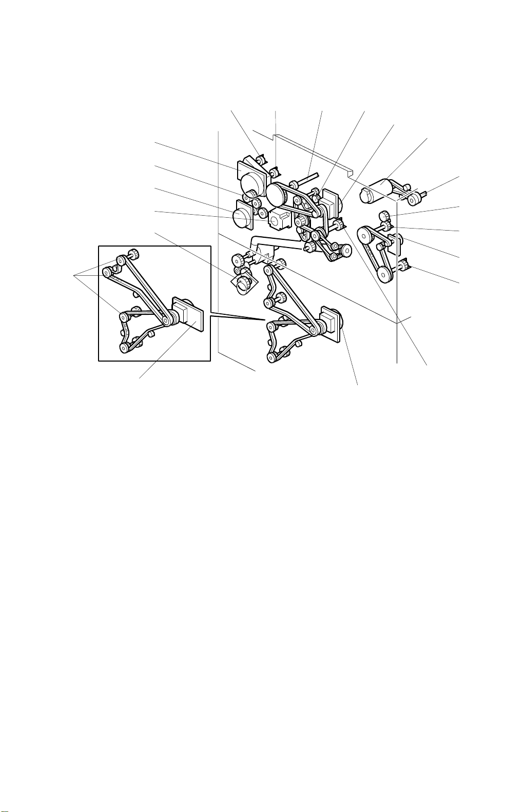
1.5 DRIVE LAYOUT
917
10
2
4
5
8
3
6
A246V505.WMF
Main Motor
Scanner Drive Motor
Fusing/Duplex Drive Motor
Paper Feed Motor
Toner Collection Motor
Registration Motor
By-pass Feed Motor
By-pass Feed Clutch
Development Drive Motor
1. To OPC Drum
2. To Scanner Unit
3. To Transfer Belt Unit
4. To Paper Exit Unit
5. To Fusing Unit
6. To Duplex Unit
7. To Cleaning Unit
8. To Paper Feed Units
9. To Toner Hopper
10. To Development Unit
1-12
Page 23
21 September 1998 PAPER PATH
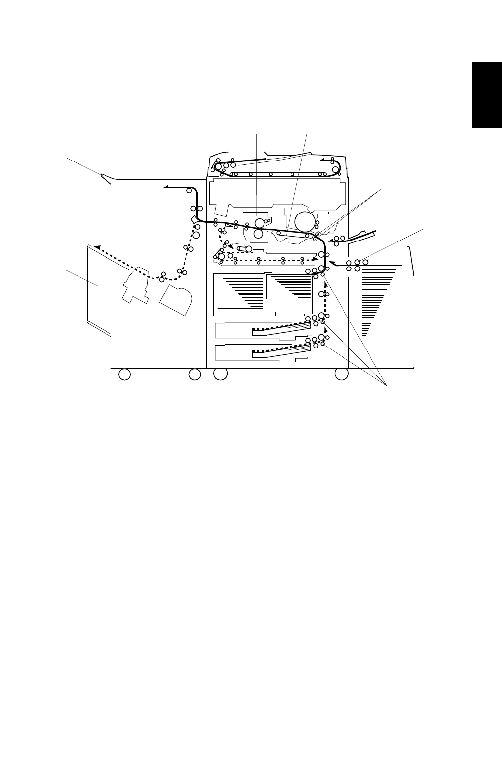
1.6 PAPER PATH
1.6.1 STANDARD COPYING
[D]
[F]
[E]
[C]
[B]
[A]
Overall
Information
[A]
A246V506.WMF
Paper feed begins from the exterior LCT, by-pass feed table or paper feed stations
in the paper tray unit. The copy paper then follows one of two paths inside the
copier. The path followed depends on which mode the operator has selected. For
copy processing, all sheets follow the same paths from the paper feed mechanism
[A] through the registration rollers [B], transfer belt [C], and fusing unit [D]. After
that, copies are delivered to the sorter bins [E] or proof tray [F], however, 2 sided
copies are diverted for further processing.
1-13
Page 24
PAPER PATH 21 September 1998
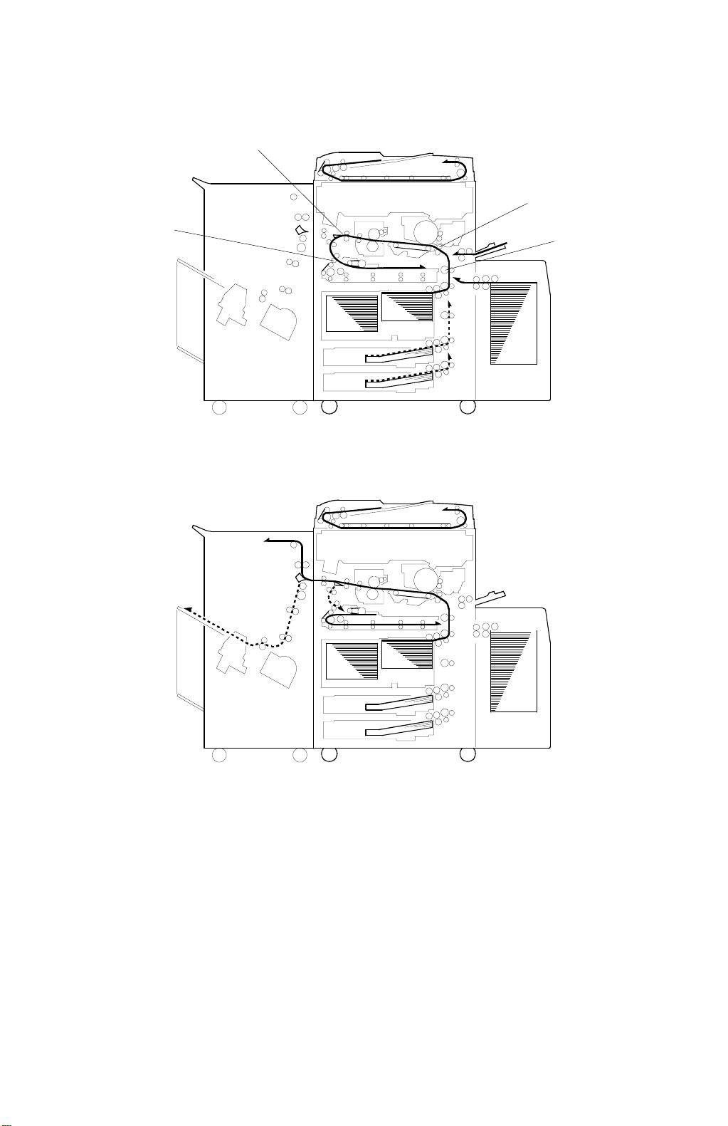
1.6.2 MULTIPLE 2-SIDE COPYING
a. Front Side
b. Rear Side
[B]
[A]
[D]
[C]
A246V507.WMF
A246V508.WMF
In this mode the junction gate [A] directs sheets exiting the fusing unit to the duplex
tray entrance. After that, all sheets follow the path through the duplex entrance
rollers [B].
After all front side copying is fed, the sheets on the duplex tray are fed in order
from the bottom to the top and follow the path through the duplex feed mechanism
and vertical transport rollers [C] to the registration rollers [D]. After that, these
sheets follow the same path as standard copying from the registration rollers to the
sorter.
1-14
Page 25

21 September 1998 ELECTRICAL COMPONENT DESCRIPTIO N
1.7 ELECTRICAL COMPONENT DESCRIPTION
Refer to the electrical component layout on the reverse side of the point-to-point
diagram for the location of the components using the symbols and index numbers.
Symbol Name Function Index No.
Motors
M1 Scanner Drives the 1st and 2nd scanners. 5
M2 3rd Scanner Drives the 3rd scanner. 11
M3 Lens Horizontal Shifts the lens vertical position. 10
M4 Lens Vertical Shifts the lens horizontal position. 19
M5 Main Drives the main unit components. 120
M6 Development Dr ives the development unit. 121
M7
M8
M9
M10
M11
M12
M13
M14
M15
M16 By-pass Feed Drives the by-pass feed rollers. 124
M17 Registration Drives the r eg istr ation rollers. 123
M18
M19
M20 Optics Cooling Fan Removes heat from the optics unit. 21
M21
M22
M23
M24
Toner Bottle
Charge Wire
Cleaner
Fusing/Duplex Drives the f using unit, the duplex unit,
Toner Collection
Toner Recycle Drives the air pump to send recycled
Paper Feed Drives all feed and transport rollers in the
1st Lift
2nd Lift Raises the bottom plate in the 2nd paper
3rd Lift Raises and lowers the bottom plat e in the
Rear Fence Moves the paper stack in the left tandem
Jogger
Optics Board
Cooling Fan
Drum Cooling Fan Cools the drum unit to removes heat
Duplex Cooling Fan
Exhaust Fan Removes heat from around the fusing
Rotates the toner bottle to supply toner to
toner hopper.
Drives the charge wire cleaner to clean
the charge wire.
and the exit rollers.
Transports the collected toner in the
toner recycle unit for toner recycle.
toner to the development unit.
paper tray unit.
Raises the bottom plate in the 1st paper
tray.
tray.
3rd paper tray.
tray to the right tandem tray.
Drives the jogger fences to square the
paper stack in the duplex unit.
Removes heat from around the optics
board.
from around the duplex unit.
Cools the paper on the duplex tray to
reduce the heat around the drum.
unit.
133
30
119
126
129
94
95
97
98
55
43
118
106
114
104
Overall
Information
1-15
Page 26

ELECTRICAL COMPONENT DESCRIPTION 21 Sept ember 1998
Symbol Name Function Index No.
Magnetic Clutches
MC1
Toner Supply
Turns the toner supply roller to supply
toner to the development unit.
122
MC2 Toner Recycling Dr ives the toner recycling unit. 125
MC3 1st Feed Starts paper feed from tray 1. 75
MC4 2nd Feed Starts paper feed from tray 2. 79
MC5 3rd Feed Starts paper feed from tray 3. 82
MC6 By-pass Feed Starts paper feed from the by-pass table. 64
Duplex Transport Drives the duplex transport rollers to
MC7
transport the paper to the vertical
39
transport rollers.
MC8
Duplex Feed Starts paper feed out of the duplex tray
to the duplex transport rollers.
38
Switches
SW1 Main Provides power to the copier. 117
SW2
SW3
SW4
Front Door Safety Cuts the power line and detects is the
front door is opened or not.
Toner Collection
Bottle
2nd Paper Size
Detects if the toner collection bottle is set
or not.
Determines what size paper is in the 2nd
paper tray.
115
128
100
SW5 3rd Tray Set Detects if the 3rd tray is set or not. 99
SW6
By-pass Table Detects if by-pass feed table is open or
closed.
62
Solenoids
SOL1
SOL2
SOL3
SOL4
SOL5
SOL6
SOL7
SOL8
SOL9
SOL10
Transfer Belt
Positioning
Controls the up-down movement of the
transfer belt unit.
1st Pick-up Controls the up-down movement of the
pick-up roller in tray 1.
2nd Pick-up
Controls the up-down movement of the
pick-up roller in tray 2.
3rd Pick-up Controls the up-down movement of the
pick-up roller in tray 3.
By-pass Pick-up Contr ols the up-down movement of the
pick-up roller for by-pass feed.
1st Separation
Roller
2nd Separation
Roller
3rd Separation
Roller
Right Tandem Lock
Controls the up-down movement of the
separation roller in tray 1.
Controls the up-down movement of the
separation roller in tray 2.
Controls the up-down movement of the
separation roller in tray 3.
Locks the right tandem tray during
transporting the paper from right tray to
left tray.
Left Tandem Lock Locks the left tandem tray so that it can
be separated from the right tandem tray.
34
74
78
83
63
76
81
84
96
101
1-16
Page 27

21 September 1998 ELECTRICAL COMPONENT DESCRIPTIO N
Symbol Name Function Index No.
SOL11
SOL12
SOL13
SOL14
SOL15
SOL13
Front Side Fence
Rear Side Fence Contr ols the open and close movement
Duplex Positioning Controls the up-down movement of the
Pressure Arm
Guide Plate Opens the guide plate when a paper
Junction Gate Moves the junction gate to direct copies
Controls the open and close movement
of the front side fence.
of the rear side fence.
positioning roller.
Presses the paper on the duplex tray
against the duplex feed rollers.
misfeed occurs around this area.
to the duplex tray or to the paper exit.
54
49
40
44
67
60
Sensors
S1
S2
S3
S4
Scanner HP Informs the CPU when the 1st and 2nd
scanners are at the home position.
3 rd Scanner HP
Informs the CPU when the 3rd scanner is
at the home position.
Lens Vertical HP Informs the CPU when the lens is at the
full-size position.
Lens Horizontal HP Informs the CPU when the lens is at the
horizontal home position.
2
9
7
12
S5 APS Detects original size. 20
S6
Auto Image Density
Senses the background density of the
original.
6
S7 Drum Potential Det ects the drum surface potential. 31
S8
S9
Toner Density
Image Density Detects the density of the ID sensor
Detects the amount of toner in the
developer.
pattern on the drum.
37
32
S10 Toner Near End Detects the toner end condition. 36
1st Paper Feed Controls the 1st paper feed clutch off/on
S11
timing and the 1st pick-up solenoid off
91
timing.
2nd Paper Feed Controls the 2nd paper feed clutch off/on
S12
timing and the 2nd pick-up solenoid off
89
timing.
3rd Paper Feed
S13
Controls the 3rd paper feed clutch off/on
timing and the 3rd pick-up solenoid off
87
timing.
S14
S15
S16
S17
1st Lift Detects when the paper in tray 1 is at the
correct height for paper feed.
2nd Lift
Detects when the paper in tray 2 is at the
correct height for paper feed.
3rd Lift Detect s when the paper in tray 3 is at the
correct height for paper feed.
1st Paper End Informs the CPU when tray 1 runs out of
paper.
93
80
85
92
Overall
Information
1-17
Page 28

ELECTRICAL COMPONENT DESCRIPTION 21 Sept ember 1998
Symbol Name Function Index No.
S18
S19
S20
S21
S22
S23
S24
2nd Paper End
3rd Paper End Informs the CPU when tray 3 runs out of
By-pass Paper End Informs the CPU that there is no paper in
1st Paper Near End
2nd Paper Near
End
3rd Paper Near End Informs the CPU when the paper in tray
Right Tray Down
Informs the CPU when tray 2 runs out of
paper.
paper.
the by-pass feed table.
Informs the CPU when the paper in tray
1 is almost finished.
Informs the CPU when the paper in tray
2 is almost finished.
3 is almost finished.
Informs the CPU when the bottom plate
is completely lowered, to stop the 1st tray
90
88
65
53
77
86
52
lift motor.
S25
S26
S27
S28
S29
S30
S31
S32
Right Tray Paper Detects whether there is paper in the
right tandem tray.
Front Side Fence
Open
Front Side Fence
Close
Rear Side Fence
Open
Rear Side Fence
Close
Informs the CPU when the front side
fence is open.
Informs the CPU when the front side
fence is close.
Informs the CPU when the rear side
fence is open.
Informs the CPU when the rear side
fence is close.
Rear Fence HP Informs the CPU when the tandem tray
rear fence is in the home position.
Rear Fence Return Informs the CPU when the tandem tray
rear fence is in the return position.
Left Tandem Paper Informs the CPU when the left tandem
tray runs out the paper.
50
58
57
48
47
59
51
56
S33 Paper Guide Detect s the misfeeds. 61
S34
Duplex Entrance
Detects the leading edge of the paper to
determine duplex feed clutch off timing.
45
Duplex Transport Detects the leading edge of the paper to
S35
control the jogger motor and the
42
positioning solenoid on timing.
Duplex Exit
S36
Detects the leading edge of the paper to
determine duplex transport clutch on
42
timing.
S37 Duplex Paper End Detects the paper in the duplex tray. 46
S38
S39
Jogger HP Detects if the duplex jogger fences at the
home position or not.
Vertical Transport
Detects the leading edge of the paper to
determine the paper feed timing of next
41
69
sheet.
S40
Guide Plate
Position
Detects whether the registration guide
plate is closed.
68
1-18
Page 29

21 September 1998 ELECTRICAL COMPONENT DESCRIPTIO N
Symbol Name Function Index No.
S41
Registration
Detects misfeeds and controls the
registration roller on-off timing.
70
S42 Fusing Exit Detects misfeeds. 72
S43 Exit Detects misfeeds. 73
S44
S45
S46
S47
Auto Response
Toner Overflow Detects when the toner collection bottle
Original Length
(LT version only)
Platen Cover
Position 1 (Option)
Returns the display from the screen
saver.
is full.
Detects the original length.
Inform the CPU that the platen cover is in
the up or down position (related to
17
127
8
3
APS/ARE function).
S48
Platen Cover
Position 2 (Option)
Inform the CPU that the platen cover is in
the up or down position to detect if the
4
original has been removed or not.
PCBs
PCB1 Main Controls all machine functions. 107
PCB2
AC Drive Provides ac power to the fusing lamp and
exposure lamp.
102
PCB3 DC Power Supply Provides dc power. 110
PCB4 Optic Control Controls all optics components. 105
PCB5
PCB6
PCB7
Paper Feed Control Controls all components in the paper
bank.
Operation Panel
Control
Left Operation
Panel
Controls LEDs and LCD on the operation
panel.
Interfaces the LEDs, keys, and the auto
response sensor on the left operation
109
15
18
panel.
PCB8
PCB9
Right Operation
Panel
By-pass Paper Size Inform the CPU what size of the paper is
Interfaces the LEDs and keys on the right
operation panel.
in the by-pass feed table.
13
66
Overall
Information
Lamps
L1
Exposure Lamp Applies high intensity light to the original
for exposure.
L2 Fusing Lamps Provide heat t o the hot roller. 24
L3
L4
L5
Quenching Neutralizes any charge remaining on the
drum surface after cleaning.
Erase
Discharge the drum outside of the image
area.
Pre-transfer Reduce the charge on the drum surface
before transfer.
1-19
23
28
29
33
Page 30

ELECTRICAL COMPONENT DESCRIPTION 21 Sept ember 1998
Symbol Name Function Index No.
Power Packs
Charge
PP1
Provides high voltage for the charge
corona wires and the grid plate.
Interfaces the QL, PTL, and charge wire
27
cleaner motor control signals.
Development Provides hig h volt age for the
PP2
development unit.
Interfaces the transfer p.p. and the
108
charge p.p. signals.
Transfer Provides high voltage for the transfer
PP3
belt.
Interfaces the transfer belt positioning
35
solenoid control signal.
Heaters
H1
Optic
Anti-condensation
Turns on when the main switch is off to
prevent moisture from forming on the
16
optics.
H2
Transfer
Anti-condensation
Turns on when the main switch is off to
prevent moisture from forming on the
134
optics.
H3
H4
Upper Tray Turns on when the main switch is off to
keep paper dry in the paper tray.
Lower Tray
Turns on when the main switch is off to
keep paper dry in the paper tray.
131
130
Thermistors
TH1
Optic
Monitors the temperature of the optics
cavity.
TH2 Fusing Detects the temperature of the hot roller. 25
TH3
Drum Monitors the temperature of the OPC
drum.
Others
CB1
CO1
CO2
LA1
LCD1
Circuit Breaker Provides back-up high current protection
for the electrical components.
Total Counter Keeps track of the total number of copies
made.
Key Counter
Keeps track of the total number of copies
made when the key counter is set.
Lightening Arrestor Removes current surges from the ac
input lines.
LCD Displays the operation menus and
messages.
NF1 Noise Filter Remove the electrical noise. 112
RA1 Main Power Relay Contro ls main power. 103
TF1
Fusing Thermofuse Opens the fusing lamp circuit if the fusing
unit overheats.
1
32
113
132
-
116
14
26
1-20
Page 31

21 September 1998 ELECTRICAL COMPONENT DESCRIPTIO N
Symbol Name Function Index No.
TR1
TS1
Transformer
(220 V version only)
Optics
Thermoswitch
Makes power for the exposure lamp.
Opens the exposure lamp circuit if the
optics unit overheats.
111
22
Overall
Information
1-21
Page 32

21 September 1998 PROCESS CONTROL
g
2. DETAILED SECTION DESCRIPTIONS
2.1 PROCESS CONTROL
2.1.1 OVERVIEW
Ori
inal Scale
Image Density Control (Fuzzy Control)
Latent Image Control
VD Pattern VL Pattern
Latent Image Control
Exposure Control
Charge Control
Drum Thermistor
Lamp Voltage
Grid Voltage
QL
Paper
ADS Pattern
VD Pattern
L
V
Erase Lamp
Drum Potential Sensor
Detailed
Descriptions
Pattern
Original Exposure Glass
Toner Supply On Time
Development Bias
TD Sensor
ID Sensor
Image Density Control
(Fuzzy Control)
Toner Supply Control
Main PCB
A246D529.WMF
This model uses two process control methods. One compensates for variation in
the drum potential (latent image control) and the other controls the toner
concentration and toner supply amount (image density control).
2-1
Page 33

PROCESS CONTROL 21 September 1998
Latent Image Control
QL
Charge
Exposure
Black White
Erase
A246D550.WMF
The figure shows drum potential changes during the copy process.
VO: The drum potential just after charging the drum.
VD (Dark Potential): The drum potential just after exposing the black
pattern (VD pattern)
VL (Light Potential): The drum potential just after exposing the white
pattern (VL pattern)
Potential Sensor
Drum
VR (Residual Voltage): The drum potential just after the exposure to the
erase lamp.
After long usage following installation or a PM, drum potential will gradually
increase due to the following factors:
Dirty optics or exposure lamp deterioration
A dirty charge corona casing and grid plate
A change in drum sensitivity
In this copier, the drum potential sensor detects the change in drum potential and
controls the following items to maintain good copy quality:
The grid-bias voltage
The exposure lamp voltage
The development bias voltage.
A drum thermistor detects the drum temperature and acquires data. The thermistor
uses this data to control the above voltages. It is impossible to explain this process
simply because it is controlled by methods developed in our laboratories using an
artificial neural network.
2-2
Page 34

21 September 1998 PROCESS CONTROL
Image Density Control
The following sensors control image density:
Toner Density sensor (TD sensor)
Image Density sensor (ID sensor)
Data from the TD sensor maintains the toner concentration in the developer at a
constant level. However, the image on the OPC drum varies due to the variation in
toner chargeability (influenced by the environment), even if the toner concentration
is constant. Toner concentration changes to maintain the image density on the
OPC drum because of compensation by the ID sensor.
The following items are controlled to maintain a constant copy image density:
Toner supply clutch on time
Toner supply level data (V
) of the TD sensor
REF
Detailed
Descriptions
2-3
Page 35

PROCESS CONTROL 21 September 1998
g
g
2.1.2 PROCESS CONTROL DATA INITIAL SETTING
The following flow chart shows the steps performed when turning on the machine
while the hot roller temperature is below 100°C. This initializes all the process
control settings.
Main SW ON (Fusing Temp. < 100C
Charge wire cleaning (if more than 5 k copies are made since last cleanin
Drum Potential Sensor Calibration
Drum Conditioning Start (Fusing Temp. = 180°C
VSG Adjustment
Transfer belt voltage detection
VR Measurement
VD/VL Correction
)
TD Sensor Detection
ID Sensor Detection/Correction
ADS Adjustment
See Latent Image Control section
:
e 2-5) for details.
(Pa
See Image Density Control section
:
(Page 2-12) for deteails.
See Optics section (Page 2-44) for details.
:
A246D551.WMF
2-4
Page 36

21 September 1998 PROCESS CONTROL
2.1.3 LATENT IMAGE CONTROL
Drum Potential Sensor Calibration
[A]
Case
Sensor
Output
Amp.
Detailed
Descriptions
Drum
[B]
A246D554.WMF
Main PCB
A246D552.WMF
The potential sensor [A] for the drum is just above the development unit. The
sensor has a detector that detects the strength of the electric field from the electric
potential on the drum. The output of the sensor depends on the strength of the
electric field.
Since environmental conditions affect sensor output, such as temperature and
humidity, the sensor output is calibrated during process control data initialization.
The High Voltage Control PCB [B] has two relay contacts. Usually RA602 grounds
the drum. However, during the initial setting, the main PCB turns RA601 on and
RA602 off and applies the voltage to the drum shaft.
By measuring the output of the drum potential sensor when –100 V and –800 V are
applied to the drum, the sensor output is calibrated automatically. (The machine
recognizes the relationship between actual drum potential and the potential sensor
output.)
2-5
Page 37

PROCESS CONTROL 21 September 1998
Drum Conditioning
When the fusing temperature reaches 180°C, the machine starts the drum
conditioning process. In this mode, the main motor, main charge corona, erase
lamp and development bias are activated for about 30 seconds and drum
sensitivity and residual voltage (VR) are stabilized, as in continuous copy runs.
VSG Adjustment
During drum conditioning, the ID sensor checks the reflectivity of the bare drum
and calibrates the output of the ID sensor to 4 0.2 V.
VR Measurement
O
V
[-V]
D
V
New Drum
Used Drum
Drum
Potential
L
V
Original Density
R
V
LightDark
A246D561.WMF
The above figure shows the relationship between the drum potential and the
original density. This relationship must persist to maintain copy quality.
Since this relationship tends to change to the one represented by the dotted line by
various factors, some compensation is necessary.
Increasing the exposure lamp voltage cannot compensate for the residual voltage
(VR). Therefore, other means are required to compensate for VR change.
The main control board checks the drum potential just after the erase lamp
exposure with the drum potential sensor, after drum conditioning. This measured
drum potential is in fact VR. This VR is the standard for the VD and VL corrections.
NOTE:
In the figure above, the residual voltage (VR) for the new drum is 0 V.
Actually, there is some residual voltage even on a new drum.
2-6
Page 38

21 September 1998 PROCESS CONTROL
VD Correction
Exposure
D
V
[-V]
D
V
Pattern
Glass
A246D566.WMF
R
V
Drum
Potential
-770
New Drum
Original Density
R
V
VD Compensated
After many copies
LightDark
A246D568.WMF
The drum potential just after the black pattern (VD Pattern) is exposed (VD: Dark
Potential) tends to lower during drum life due to a decrease in the capacity of the
drum to carry a charge.
Detailed
Descriptions
To check the actual VD, the first scanner moves to the home position, exposing the
VD pattern (Black) stuck on the bottom side of the exposure glass bracket on the
drum.
The main control board measures VD using the drum potential sensor and adjusts
it to a target value by adjusting the grid-bias voltage (V
GRID
).
On the other hand, the drum residual voltage (VR) changes to compensate for the
target VD voltage in the following manner:
Target VD Value: VD = VR + (–770)
The adjusted grid-bias voltage (V
) remains in memory until the next process
GRID
control data initialization.
2-7
Page 39

PROCESS CONTROL 21 September 1998
VL Correction
[-V]
Drum
Potential
-770
D
V
V
-140
Exposure
Glass
A246D566.WMF
VL Pattern
R
V
R
Original Density
Only VD Compensated
L
V
VD and VL Compensated
LightDark
A246D594.WMF
New Drum
R
V
Dirty optics and/or exposure lamp deterioration decreases the intensity of the light
that reaches the drum. In addition to this, the drum sensitivity also changes during
the life of the drum. These factors change the drum potential just after white pattern
exposure (VL: Light Potential).
To check the actual VL, the lens moves to the VL pattern check position. This
exposes the VL pattern (White) stuck underneath the original scale on the drum.
The main control board measures VL using the drum potential sensor and adjusts it
to a target value by adjusting the exposure lamp voltage (V
LAMP
).
The residual voltage (VR) change also affects VL, to compensate for the target
voltage of VL in the following manner:
Target VL Value: VL = VR + (–140)
The adjusted exposure lamp voltage (V
) is stored in memory until the next
LAMP
initial setting of the process control data.
2-8
Page 40

21 September 1998 PROCESS CONTROL
VR Correction
[-V]
D
V
R
V
Drum
Potential
-770
V
-140
L
V
R
Development Bias (VBB)
VD and VL Compensated
New Drum
R
V
Detailed
Descriptions
Dark Light
Original Density
A246D602.WMF
The potential sensor monitors potentials (VR, VD, and VL). During the check cycle,
the VD and VL patterns are exposed. The potential sensor checks the drum
potential in the area exposed by each pattern.
Compare the curve of the VD and VL compensated drum potential with the curve of
the new drum, they are parallel but the compensated potential is still higher (VR)
than the new drum potential. To prevent dirty backgrounds due to increased
residual potential, development bias (VBB) is applied as follows:
VBB = VR + (–220)
2-9
Page 41

PROCESS CONTROL 21 September 1998
Initial Setting Sequence
The following graph shows the sequence of events during the initial setting of the
process control data.
For the purpose
of ADS sensor
correction
Exposure
Lamp
Potential
Sensor
Output
800
V
100
V
1. Potential
sensor
2. VR’, VD’, VL’
Latent Image Control
V
R
V
potential
D
L
V
New V
3. V
D
D
New V
New V
New V
R
D, VL
correction
L
4. ID sensor
pattern
potential
A246D604.WMF
1. Potential sensor calibration
Measuring the output of the drum potential sensor when applying –100 V and –
800 V to the drum, automatically calibrates the sensor output (V
100
and V
See page 2-5 for details.
800
).
2. VR, VD, VL potential detection
After about 30 seconds of drum conditioning, VD and VL Patterns are
developed by using the previous grid-bias voltage (V
lamp voltage (V
The machine calculates the new V
) data to detect the VR, VD, VL data.
LAMP
and V
GRID
data using the detected VR,
LAMP
) data and exposure
GRID
VD, and VL data.
2-10
Page 42

21 September 1998 PROCESS CONTROL
3. VD and VL corrections
Using the calculated V
GRID
and V
data, the VR, VD, and VL patterns are
LAMP
redeveloped thereby determining the new VR, VD, and VL data. If both VD and
VL data are within specifications, the new VD, VL, and VR values determine the
new V
GRID
, V
and development bias (VBB).
LAMP
Specifications:
VD = –770 + VR 20 V
VL = –140 + VR 20 V
If VD is outside specifications, V
measured and VD is detected again. The same is done for VL and V
is shifted one step. Then the VD pattern is re-
GRID
LAMP
. The
above process continues until both VD and VL fall within specifications. The graph
on the previous page shows an example of when only VL was outside the
specifications at the first VL detection. It came within specifications after one V
correction by changing V
0.5 V/step, and V
LAMP
by 20 V/step.
GRID
L
Detailed
Descriptions
The machine stops VD/VL correction and uses the previous V
GRID
and V
LAMP
values during copying in the following instances:
If V
100
or V
at the calibration of the drum potential sensor is outside
800
specifications.
If VD or VL does not fall within specifications after shifting V
GRID
or V
LAMP
their maximum and/or minimum levels.
In this case, the machine indicates nothing, but the SC counter increments.
Related SC codes (see troubleshooting section for details):
Code Condition
361 Incomplete drum potential sensor calibration
364 Abnormal VD detection
365 Abnormal VL detection
366 VR abnormal
Utilizing VR in the following manner can also determine the development bias:
VBB = VR + (–220)
4. The ID sensor pattern for potential detection
This determines the ID Sensor Bias Voltage. The development control section
explains this subject in more detail (see page 2-16).
to
2-11
Page 43

PROCESS CONTROL 21 September 1998
2.1.4 IMAGE DENSITY CONTROL
Toner Density Sensor
OUT
A: V
B: V
C: V
(Gain data) is high.
OUT
is within the specification.
OUT
(Gain data) is
low
IN
V
OUT IN X
V=V
= 12 x
.
Main PCB
V
AGC
Gain
256
Gain
256
OUT
D
V
(12 V)
GND
Sensor
Output
TD
Sensor
A246D606.WMF
A246D531.WMF
Developer consists of carrier particles (iron) and toner particles (resin and carbon).
Inside the development unit, developer passes through a magnetic field created by
coils inside the toner density sensor. When the toner concentration changes, the
voltage output by the sensor changes accordingly.
<Toner Density Sensor Initial Setting>
When installing new developer with the standard toner concentration (2.0% by
weight, 20 g of toner in 1,000 g of developer), the initial setting for the developer
must be performed by using an SP mode (SP1-2-1).
During this setting, the output voltage (V
) from the auto gain control circuit
OUT
(AGC) on the main control board PCB varies to change the output voltage from the
toner density (TD) sensor. Changing the gain data does this:
V= V x
OUT IN
Gain Data
256
12 x
Gain Data
256
If the data is large, V
results in the sensor sensitivity illustrated by curve A. If the data is small, V
and the sensor output voltage also become large. This
OUT
OUT
becomes small, and the sensor output voltage becomes small. As a result, the
sensor sensitivity shifts as illustrated by curve C.
2-12
Page 44

21 September 1998 PROCESS CONTROL
By selecting the proper gain data, the sensor output is set within the targeted
control level (V
REF
, V
= 2.5 0.1 V). Now, curve B shows the sensor
REF
characteristic and the TD sensor initial setting is complete.
The selected gain data is stored in memory, and V
from the auto-gain control
OUT
circuit stays constant during the detection cycle for the toner sensor.
<Toner Supply Criteria>
Toner density detection in the developer occurs once in every copy cycle. The
sensor output voltage (VTD) during the detection cycle is compared with the toner
supply level voltage (V
REF
).
Detailed
Descriptions
2-13
A246D609.WMF
Page 45

PROCESS CONTROL 21 September 1998
<Toner Supply Clutch on Period>
To stabilize toner concentration, the toner supply (toner supply clutch ON period) is
controlled by using V
and VTD data.
REF
The toner supply is calculated after each copy. The following factors determine the
remaining toner supply:
V
V
– V
REF
REF
TD
– VTD’(VTD’ = VTD of the previous copy cycle)
A246D512.WMF
By referring to these factors, the machine recognizes the difference between the
current and target toner concentration. The machine also understands how much
the toner concentration changed and can predict how much the toner supply
amount will probably change.
Precision changes in the toner supply maintain the toner concentration (image
density). Since updating the toner supply clutch ON period is under fuzzy control,
the relation among VTD, VTD’, V
cannot be expressed by a simple algebraic
REF
formula.
<V
Correction>
REF
The image on the OPC drum changes du e to the variation in toner chargeability
(influenced by the environment) even if the toner concentration is constant. The
image density sensor (ID sensor) directly checks the image on the OPC drum and
shifts V
data (under fuzzy control) to keep the image on the OPC drum
REF
constant, as explained in the next section.
NOTE:
1) The toner end sensor detects the toner end condition (see the
development section for details).
2) The toner supply clutch turns on at intervals between each copy
process, while image development is not occurring.
2-14
Page 46

21 September 1998 PROCESS CONTROL
Image Density Sensor Detection
[B]
[C]
Drum
[A]
Bias
A246D514.WMF
A246D513.WMF
The ID sensor [A] checks VSG and VSP. The ID sensor is located underneath the
drum cleaning section.
There is no ID sensor pattern in the optics; however, the charge corona unit [B] and
the erase lamp [C] make a pattern image on the OPC drum.
Detailed
Descriptions
VSG is the ID sensor output when checking the erased drum surface.
VSP is the ID sensor output when checking the ID sensor pattern image.
To compensate for any variation in light intensity from the sensor LED, the
reflectivity of both the erased drum surface and the pattern on the drum are
checked.
VSP Detection
SG
V
Detection
1st Series of
Copies (8 copies)
2nd Series
of Copies
(5 copies)
SG
V
Detection
VSP Detection
V
Detection
SG
3rd Series
of copies
(17 copies)
SP
Detection
V
SG
V
Detection
A246D515.WMF
VSG is detected every time the machine starts copying.
During VSG detection, the development sleeve rollers do not rotate and
development bias is not applied.
If 10 or more copies are made, the copier will re-detect VSP. Since the transfer belt
must be released when checking VSP, the machine cannot check the VSP during
continuous copying.
2-15
Page 47

PROCESS CONTROL 21 September 1998
Potential
Sensor Detection
V
ID Sensor
Bias Level
4.0 V
ID Sensor
Output
P
V
–800
P
IDB
V
= VP + 300 (V)
–300
SP
V
A246D516.WMF
A246D517.WMF
While developing the ID sensor pattern, ID sensor bias is applied. ID sensor bias is
determined during process control data initialization as follows:
Apply charge while the grid voltage is –800 V to create the ID sensor pattern.
Check the drum potential (VP) of the latent image created by the charge with –800
V grid.
Adjust the ID sensor bias (V
V
= VP – (–300) (V)
IDB
) so that it satisfies the following formula:
IDB
= VP + 300 (V)
Change the bias to the calculated V
and detect VSP. The VSG value detected
IDB
during its adjustment sequence during process control data initialization and the
VSP determine the V
data. The V
REF
does not change until the next initial
IDB
setting for the process control data.
<V
After the series of copies is completed, when 10 or more copies were made, V
is updated by referring to the previous V
Correction Timing>
REF
REF
(V
’), VSG, VSP and the current TD
REF
REF
sensor output (VTD).
Since this V
V
’, VSG, VSP and VTD cannot be expressed in a simple algebraic for mula.
REF
The V
is not only updated in the above case, but also during the initial setting
REF
data updating is under fuzzy control, the relationship among V
REF
for the developer and during process control data initialization.
2-16
REF
,
Page 48

21 September 1998 PROCESS CONTROL
Sensor Abnormal Conditions
a) ID sensor (VSG, VSP) abnormal
Whenever V
data and the TD sensor output controls the toner concentration.
Normal detection of VSG and VSP occurs, as usual, during abnormal conditions. If
output returns to normal levels (VSG 2.5 V, VSP 2.5 V), the CPU returns the
toner concentration control to normal mode.
b) TD sensor (V
Whenever V
to the fixed supply mode. In this condition, the CPU never stops the toner supply.
The fixed toner supply can be changed in four steps (4%, 7%, 11%, and 14%) by
using an SP mode. The default fixed toner supply is 4%.
Detection of VTD still occurs, as usual, during abnormal conditions. If its output
returns to a normal level, the CPU returns the toner concentration control to normal
mode.
falls under 2.5 V or VSP rises over 2.5 V, the CPU fixes the V
SG
) abnormal
TD
rises over 4.0 V or falls under 0.5 V, the CPU shifts the toner supply
TD
REF
Detailed
Descriptions
c) Drum Potential Sensor abnormal
The CPU shifts the toner supply to fixed supply mode, when the TD sensor (VTD)
detects an abnormal condition, in the following cases:
V
V
rises over 0.7 V or falls under 0.1 V
100
rises over 4.2 V or falls under 2.7 V
800
Related SC codes. (See troubleshooting section of details.):
Code Condition
351
352 Incomplete TD Sensor Initial Setting
353
354
355
356
358
361 Incomplete Drum Potential Sensor Calibration
Abnormal V
Abnormal V
Abnormal V
Abnormal V
Abnormal V
Abnormal V
Detection (VSG 4.2 V)
SG
Detection (VSP 2.5 V)
SP
Detection (VSG 2.5 V)
SG
Detection (VTD 4.7 V)
TD
Detection (VTD 0.5 V)
TD
SP/VSG
Detection (VSP/VSG 0.025 V)
2-17
Page 49

DRUM UNIT 21 September 1998
2.2 DRUM UNIT
2.2.1 OVERVIEW
12
13
11
10
1514
9
7, 8 62
16
1
3
4
5
A246D518.WMF
The drum unit consists of the components as shown in the above illustration. This
model uses an organic photoconductor drum (diameter: 100 mm).
1. OPC Drum
2. Paper Guide Spurs (60/70 cpm only)
3. Erase Lamp
4. Drum Potential Sensor
5. Pre-transfer Lamp
6. Pick-off Pawl
7. Image Density Sensor
8. Drum Thermistor
9. Cleaning Brush
10. Toner Collection Coil
11. Cleaning Blade
12. Ozone Filter
13. Cleaning Filter
14. Charge Power Pack
15. Quenching Lamp
16. Main Charge Corona Unit
2-18
Page 50

21 September 1998 DRUM UNIT
2.2.2 OPC DRUM CHARACTERISTICS
An OPC has the following characteristics:
1) Accepts a high negative electrical charge in the dark. (The electrical
resistance of a photoconductor is higher with the absence of light.)
2) Dissipates the electrical charge when exposed to light. (Exposure to light
greatly increases the conductivity of a photoconductor.)
3) Dissipates an amount of charge in direct proportion to the intensity of the
light. That is, the stronger the light focused on the photoconductor surface is,
the smaller the voltage remaining on the OPC.
4) Less sensitive to changes in temperature (when compared to selenium F
type drums).
5) Less sensitive to changes in rest time (light fatigue). This makes it
unnecessary to compensate for the development bias voltage resulting from
variations in the rest time.
Detailed
Descriptions
2-19
Page 51

DRUM UNIT 21 September 1998
2.2.3 DRUM CHARGE
Overview
[A]
A246D519.WMF
This copier uses a double corona wire scorotron system for the drum charge. Two
corona wires are required to give sufficient negative charge on the drum surface
because of a rather high drum speed (50/51 cpm machine: 330 mm/seconds, 60
and 70 cpm machines: 430 mm/seconds.). The stainless steel grid plate makes the
corona charge uniform and controls the amount of negative charge on the drum
surface by applying negative grid-bias voltage.
The charge power pack [A] supplies constant current to the corona wires (–1,200
A). Bias voltage supplied to the grid plate is automatically controlled to maintain
proper image density even if the OPC drum potential changes due to a dirty grid
plate or the charge corona casing.
2-20
Page 52

21 September 1998 DRUM UNIT
Air Flow Around the Drum
[A]
[C]
[E]
[D]
[B]
A246D520.WMF
The exhaust fan [A] located above the fusing unit provides an airflow to the charge
corona unit to prevent uneven build-up of negative ions that can cause an uneven
charge on the drum surface as shown.
An ozone filter [B] absorbs the ozone (O3) around the drum.
The exhaust fan rotates slowly during stand-by and rotates quickly during copying
to keep the temperature inside the machine constant.
Detailed
Descriptions
There is another fan (the drum-cooling fan [C]), which is located on the right rear
side of the machine (front view). The drum-cooling fan cools the drum unit to
remove the heat from the duplex tray. The drum has 12 holes in each drum flange
[D]. Air flows into the drum, through the holes in the drum flange. To prevent
foreign matter from entering the inside of the copier, there is a dust protection filter
in the entrance [E] of the duct.
2-21
Page 53

DRUM UNIT 21 September 1998
Charge Wire Cleaning Mechanism
[A]
[C]
[A]
[C]
[B]
A246D521.WMF
The flow of air around the charge corona wire may deposit toner particles on the
corona wires. These particles may interfere with charging and cause low-density
bands on copies.
The wire cleaner pads [A] automatically clean the wires to prevent such a problem.
A DC motor [B] drives the wire cleaner. Normally the wire cleaner [C] is in the front-
end position (home position). After 5,000 copies and when the fusing temperature
is less than 100°C after the main switch is turned on, the wire cleaner motor brings
the wire cleaner to the rear end and then back to the home position.
When the wire cleaner moves from the rear to the home position (black arrow in
the illustration), the wire cleaner pads clean the wires.
There are no home-position and return-position sensors. The CPU monitors the
input voltage (5 V). When the wire cleaner reaches the end, it is stopped and the
motor locks. At this time, input voltage slightly decreases (to about 4 V) and the
CPU determines when to reverse the motor.
2-22
Page 54

21 September 1998 DRUM UNIT
2.2.4 ERASE
Overview
L
E
E
L
E
S
S
E
O
L
C
L
Detailed
Descriptions
A246D522.WMF
LE: Lead edge erase margin 3.5 2.5 mm
SE: Side erase margin total of both sides 3 mm or less
LO: Original width
LC: Charged width of drum
EL: Lead edge erase
ES: Side erase
The erase lamp unit consists of a line of 123 LEDs extending across the full width
of the drum, the width of each being about 2.5 mm. In editing mode, the customer
determines the active LEDs.
2-23
Page 55

DRUM UNIT 21 September 1998
Lead Edge and Trail Edge Erase
The entire line of LEDs turns on when the main motor turns on. They stay on until
the erase margin slightly overlaps the leading edge of the original image on the
drum (leading edge erase margin). It prevents the shadow of the original leading
edge from appearing on the copy paper. This lead erase margin is also necessary
for the leading edge of the copy paper to separate from the hot roller. An SP mode
can adjust the width of the leading edge erase margin (SP1-2-4).
When the scanner reaches the return position, the charge corona, the grid bias,
and the exposure lamp turn off. However, the charged area on the drum surface is
a little longer than the original length in order to capture the entire latent image of
the original.
The entire line of LEDs turns on when the trail edge of the latent image passes
under the erase lamp unit. This prevents developing unnecessary parts of the drum
surface; thereby reducing toner consumption and drum cleaning load.
The LEDs remain on, erasing the leading edge of the latent image in the next copy
cycle. After the final copy, the erase lamps turn off at the same time as the main
motor.
Side Erase
Based on the combination of copy paper size and the reproduction ratio data, the
LEDs turn on in blocks. This prevents the shadow of the original side edge and
unexposed front and rear sides of the drum surface in reduction mode from being
developed. This reduces toner consumption and drum cleaning load.
In the DJF mode, the horizontal original standard position on the exposure glass is
5 mm away from the rear scale.
On the other hand, the horizontal original standard position on the exposure glass
in the platen cover mode is the rear scale edge.
One more LED at the front side turns on to erase the shadow made by the edge of
the rear scale in platen cover mode. This is in addition to the LEDs that are on in
DJF mode.
2-24
Page 56

21 September 1998 DRUM UNIT
2.2.5 CLEANING
Overview
[A]
4 mm
[C]
A246D523.WMF
[B]
Detailed
Descriptions
[D]
A246D524.WMF
This copier uses the counter blade system for drum cleaning.
The blade [A] is angled against the drum rotation. This counter blade system has
the following advantages:
Causes less wear on the cleaning blade edge.
Has a high cleaning efficiency.
Due to the high efficiency of this cleaning system, this copier does not use the precleaning corona and cleaning bias.
The cleaning brush [B] supports the cleaning blade.
The brush collects toner from the drum surface and the cleaning blade scrapes the
toner off the brush. Toner on the cleaning brush is scraped off by the mylar [C] and
falls to the toner collection coil [D]. The toner collection coil transports the toner to
the toner recycle unit.
To remove the accumulated toner at the edge of the cleaning blade, the drum
reverses about 4 mm at the end of every copy job. The cleaning brush removes the
accumulated toner by this action.
2-25
Page 57

DRUM UNIT 21 September 1998
Drive Mechanism
[C]
[A]
[E]
[B]
[E]
[D]
A246D525.WMF
The timing belt [A] and the cleaning unit coupling [B] transmit drive from the drum
motor to the cleaning unit drive gear. The cleaning unit drive gear [C] then
transmits the drive to the front through the cleaning brush [D]. The gear at the front
drives the toner collection coil gear [E].
2-26
Page 58

21 September 1998 DRUM UNIT
Toner Collection Mechanism
[C]
[C]
[A]
[B]
A246D527.WMF
The toner collection tube [A] transports toner collected by the cleaning unit to the
toner recycle unit.
Drive belts [C] from the main motor drive the toner transport coil [B].
Detailed
Descriptions
2-27
Page 59

DRUM UNIT 21 September 1998
Cleaning Blade Pressure Mechanism and Side-to Side Movement
[C]
[A]
[D]
[D]
[B]
A246D526.WMF
The spring [A] always pushes the cleaning blade against the drum. Pushing up the
release lever [B] manually releases the cleaning blade pressure. To prevent
cleaning blade deformation during transportation, the release lever must be locked
in the pressure release (upper) position.
The pin [C] at the rear end of the cleaning blade holder touches the cam gear [D],
which moves the blade from side to side. This movement helps to disperse
accumulated toner, preventing early wear of the blade edge.
2-28
Page 60

21 September 1998 DRUM UNIT
Pick-off Mechanism
[A]
Detailed
Descriptions
[B]
A246D528.WMF
The pick-off pawls are always in contact with the drum surface because of weak
spring pressure. They move from side to side during the copy cycle to prevent
drum wear at any particular location. A shaft [A] and a cam [B] create this
movement.
2-29
Page 61

DRUM UNIT 21 September 1998
2.2.6 QUENCHING
[A]
A246D530.WMF
In preparation for the next copy cycle, light from the quenching lamp [A] neutralizes
any charge remaining on the drum.
The quenching lamp consists of a line of 16 LEDs extending across the full width of
the drum.
2-30
Page 62

21 September 1998 DRUM CLEANING AND TONER-RECYCLING
2.3 DRUM CLEANING AND TONER-RECYCLING
2.3.1 TONER TRANSPORT
[A]
[E]
[B]
[F]
[D]
[C]
A246D500.WMF
The toner transport tube transports the toner collected by the drum cleaning [A]
and transfer belt [B] units to the toner-recycling unit [C]. The toner transport coil [D]
transports the toner. The main motor [E], using timing belts, pulleys, and gears,
drives the transport coil. To ensure good toner flow, a fin [F] breaks up the toner
that drops from the tube of the drum-cleaning unit.
Detailed
Descriptions
2-31
Page 63

DRUM CLEANING AND TONER-RECYCLING 21 September 1998
2.3.2 FILTERING
[D]
[A]
A246D501.WMF
[D]
[B]
[D]
[B]
[C]
[C]
A246D502.WMF
[D]
[E]
A246D503.WMF
A246D504.WMF
The toner collected by the toner transport coil is delivered to the filtering unit [A].
The filtering unit consists of a mesh filter [B] and agitation bar [C]. The re-usable
toner passes through the holes in the mesh filter. The agitation bar in the mesh
filter prevents the holes in the mesh filter from being blocked.
When the coil rotates, the ball [D] stays in t he groove in the toner exit coil, and
prevents the toner from blocking the holes in the mesh filter.
The unusable material (blocked toner and paper dust) does not pass though the
holes in the mesh filter. It exits from the mesh filter and drops into the opening [E],
which leads to the toner collection bottle.
2-32
Page 64

21 September 1998 DRUM CLEANING AND TONER-RECYCLING
2.3.3 PUMP MECHANISM
[A]
[F]
[B]
[E]
A246D505.WMF
[B]
[D]
[C]
Detailed
Descriptions
[D]
[C]
[D]
[C]
A246D506.WMF
The screw in the toner-recycling unit delivers the re-usable toner to the screwpump unit [B] when the toner-recycling clutch [A] is activated.
The screw-pump consists of a rotor [C] and stator [D]. The rotor turns inside the
stator, and the screw-pump transports the toner as shown. The toner recycle motor
[E] pushes air into the screw-pump, blowing the toner from the screw-pump into the
development unit ([E] on the next page) through the toner-recycling tube [F].
The toner hopper has two air pressure release filters ([F] on the next page)
because of the amount of air sent to the toner hopper. When the toner supply
clutch remains on for 9.3 seconds or the copying time reaches 60 seconds,
whichever comes first, the toner-recycling clut ch turns on for 2 seconds. The air
pump motor turns on for 6 seconds at the same time as the toner-recycling clutch.
2-33
Page 65

DRUM CLEANING AND TONER-RECYCLING 21 September 1998
2.3.4 DRIVE MECHANISM
[F]
[E]
[A]
[B]
[D]
[C]
A246D507.WMF
The toner-collection motor [B] drives the exit coil [A] for the toner using gears. The
toner-recycling clutch [C] and gears drive the pump-unit. The toner recycle motor
[D] supplies air.
When the tone r-collection motor locks, the LCD displays an SC345 (tonercollection motor abnormal) message. If the toner recycle motor disconnects for
more than one second, the LCD displays an SC346 (toner recycle motor
disconnected) error message.
2-34
Page 66

21 September 1998 DRUM CLEANING AND TONER-RECYCLING
2.3.5 TONER COLLECTION BOTTLE
[A]
[B]
Detailed
Descriptions
A246D508.WMF
The set switch [A] for the toner collection bottle detects whether it is set properly.
The operation panel indicates when the bottle is not set correctly. The toner
overflow sensor [B] detects when the toner collection bottle becomes full. In this
condition, the copy job can end, or make up to 100 continuous copies. Then
copying is disabled and the LCD displays the service call “full toner collection
bottle”. De-actuating and then actuating the set switch for the toner collection bottle
can clear this condition.
2-35
Page 67

OPTICS 21 September 1998
2.4 OPTICS
2.4.1 OVERVIEW
[A] [B] [C]
[E]
[D]
A246D532.WMF
The optics unit reflects an image of the original from the exposure glass onto the
OPC drum. This forms a latent electrical image of the original.
This model utilizes a halogen lamp (85 V 200 W: A246 copier, 225 W: others) for
the exposure lamp [A]. The lamp surface is frosted to ensure even exposure.
Six mirrors are used to make the optics unit smaller and obtain a wide reproduction
range ratio (50 ~ 200%).
Two stepper motors drive the lens [B] (1) vertically (parallel to the paper feed
direction) and (2) horizontally.
A stepper motor changes the position of the third scanner unit [C] (4th and 5
th
mirrors) to correct the focal length changes during reduction and enlargement
modes.
The toner shielding filter [D] is green (a green filter partly absorbs red light) to
improve duplication for red originals.
The optic anti-condensation heater [E] (located on the optic base plate) turns on
while the main switch is off to prevent moisture from forming on the optical
equipment.
2-36
Page 68

21 September 1998 OPTICS
2.4.2 SCANNER DRIVE
[A]
[B]
[D]
[C]
[E]
A246D533.WMF
The scanner drive motor [A] is a DC servomotor. The scanner drive speed is 330
mm/second (50/51-CPM version) or 430 mm/second (other versions) during
scanning. When the scanner goes back, scanner drive speed is 1,950 mm/second
(50/51, 60-CPM versions). For the 70-CPM version, the scanner drive speed
changes in relation to the paper size.
Detailed
Descriptions
Paper size
DLT X B4
B4 X A4 lengthwise
A4 lengthwise X LT sideways
LT sideways X B5 sideways
B5 sideways X A5 sideways
A5 sideways X
A248 copiers scanner return speed
(mm/seconds)
1,580
1,650
2,000
2,000
1,900
1,550
X: Paper size
The scanner drive motor drives the first [B] and second scanners [C] using two
scanner drive wires via the timing belt [D] and the scanner drive shaft [E]. The
second scanner speed is half the speed of the first scanner.
2-37
Page 69

OPTICS 21 September 1998
(
)
2.4.3 VERTICAL LENS DRIVE
- EU and Asia - - U.S.A. -
[B]
[A]
[B]
[A]
A246D614.WMF
A246D534.WMF
Home position
(100%)
Enlarge Reduce
(Enlarge home
position)
(Reduce home
position)
(Enlarge Enlarge)
(Reduce Reduce)
Enlarge Reduce
(Reduce Enlarge)
30 30 30 30 steps
A246D535.WMF
The vertical drive motor [A] for the lens changes its vertical position in accordance
with the selected reproduction ratio.
A stepper motor (approx. 0.095 mm/step) shifts the lens using a drive belt. The
maximum vertical-shift distance for the lens is 290 mm (from its position at 50% to
200%). The vertical HP sensor [B] detects the vertical position of the lens in fullsize mode. The optics control PCB keeps track of its position by the number of
pulses sent to the vertical drive motor.
2-38
Page 70

21 September 1998 OPTICS
2.4.4 HORIZONTAL LENS DRIVE
- EU and Asia - - U.S.A.-
Detailed
Descriptions
[A]
A246D615.WMF
Enlarge
Home position
Reduce
[A]
A246D536.WMF
40 steps
40
40
A246D537.WMF
The original horizontal position on the exposure glass varies depending on the
mode (such as platen or DJF modes) to make it easier to handle the original.
However, the central paper feed is the standard position for paper.
Therefore, the horizontal position of the lens must change according to the paper
size, reproduction ratio and original feed and edit modes (centering, margin adjust,
etc.).
A stepper motor (approx. 0.07 mm/step) moves the lens using the drive belt. The
horizontal HP sensor [A] for the lens detects its horizontal position for A4/LT
sideways original, in full-size and platen modes.
The other positions are determined by counting the number of motor drive pulses.
Since this model has a horizontal lens drive mechanism, side-to-side registration
adjustment for each feed station can be done easily using an SP mode (SP1-1-1
Side to Side Registration Adj.).
2-39
Page 71

OPTICS 21 September 1998
2.4.5 HORIZONTAL LENS POSITIONING
For Original Position
[A]
Copy Paper
Center
Horizontal
Lens Position
[C]
[B]
A246D538.WMF
A246D539.WMF
There are two standard positions for the original in platen and DJF modes.
In platen mode, the original aligns with both the rear [A] and the left [B] original
alignment scales (rear left corner [C] is the standard position).
In DJF mode, the original position is 5 mm in front of the platen-mode original
position to maintain the original transport path (5 mm from the rear scale).
The above figure shows the horizontal lens positions in each mode when using one
paper size.
For Paper Size
Original Rear Edge
Lens Position
Copy Paper
Horizontal
A246D540.WMF
To maintain high paper feed performance, the central paper feed is the standard
position for paper. Consequently, the horizontal lens position changes according to
the paper size.
The figure shows the lens horizontal position for each paper size in full-size mode.
2-40
Page 72

21 September 1998 OPTICS
For Reproduction Ratio
<Original Rear Edge>
50%100%200%
50%
100%200%
3rd Scanner Position
Copy Paper
A246D541.WMF
When the reproduction ratio changes, so does the vertical position of the lens. At
the same time, the total focal length must shift to adjust the focus of the image. To
change the focal length, the vertical position of the 3rd scanner adjusts to a
maximum distance of 50 mm (from its position at 100% to the position at 50 or
200%).
Detailed
Descriptions
The figure shows the lens horizontal position at 50, 100 and 200%.
2-41
Page 73

OPTICS 21 September 1998
(
)
2.4.6 3RD SCANNER DRIVE
[B]
[A]
A246D542.WMF
(Initialize)
(Reduce/Enlarge
(Reduce/Enlarge Reduce/Enlarge)
Reduce/Enlarge Reduce/Enlarge
(Reduce/Enlarge Enlarge/Reduce)
40 steps40 steps
A246D543.WMF
For the focus to compensate for reproduction and lens position changes, the 3rd
scanner (4th and 5th mirrors) position is changed.
The 3rd scanner drive uses a stepper motor [A] (approx. 0.095 mm/step).
The 3rd scanner HP sensor [B] detects the unit position for ful l- si z e mode. The
optics control PCB keeps track of the unit position from the number of motor drive
pulses.
2-42
Page 74

21 September 1998 OPTICS
d
2.4.7 OPTICS CONTROL CIRCUIT
Sensors
Encoder
Data
Main
Control
Board
Bus
Main
CPU
Exposure Lamp
Optics Control Board
Optics
Control
CPU
AC Drive
Board
Optic Thermistor
A246D544.WMF
Scanner Drive
Horizontal Lens Drive
Vertical Lens Drive
r
3
Scanner Drive
Optic Cooling Fan
The optics control board communicates with the main board through a data bus. It
monitors all the sensor signals, encoder and thermistor output and controls all the
motors for optics.
Detailed
Descriptions
At the programmed time, the main CPU sends a scanner start signal to the optics
control CPU.
The CPU generates a pulse-width modulation (PWM) signal. The PWM signal goes
to a driver circuit, which sends drive pulses to the scanner drive motor.
An encoder in the scanner drive motor generates pulse signals. A speed/direction
control circuit monitors the scanner speed and the direction of the signals, and
uses this data to regulate the motor speed.
The HP sensor monitors the position of the scanner. After turning on the copier, the
main CPU confirms the scanner position by moving the scanner out of the home
position and back again. This data is sent to the optics control CPU.
2-43
Page 75

OPTICS 21 September 1998
2.4.8 AUTOMATIC IMAGE DENSITY CONTROL SYSTEM (ADS)
[B]
[A]
A246D545.WMF
In ADS mode, the ADS sensor [A] detects the density of the original background
[A]. The main CPU determines an appropriate development bias voltage for the
original to prevent dirty backgrounds from appearing on copies.
The ADS sensor board is on the rear side of the optics side plate. The sensor
housing cover, which has a small hole to direct the reflected light from the original
to the ADS sensor, covers the sensor board.
The machine adjusts the ADS sensor standard voltage to 2.7 V when process
control data initialization is performed. The exposure lamp turns on with ID level 4
at the home position and the light reflected by the ADS pattern [B] (white painted)
reaches the ADS sensor. The main CPU adjusts the ADS gain data automatically
to make the output 2.7 V. The RAM board stores this data.
2-44
Page 76

21 September 1998 OPTICS
9.7
A=
(mm)
M
90 mm
M=1.0 (m=50~100)
m
M=
(m=101~200)
100
20 mm
B=
8.25
x100 (mm)
m
m: reproduction ratio
(50~200)
A
[V]
B
ADS Original Voltage
Detailed
Descriptions
ADS
Sensor
Output
Peak hold
A246D546.WMF
For the first scanning of an original in ADS mode, the CPU starts sampling the ADS
sensor output while exposing the ADS pattern at the scanner home position. Then
the CPU stores the maximum ADS sensor output as a reference voltage. This
means that during every ADS check cycle the ADS reference voltage is renewed. It
is renewed by the latest exposure light reflected from the ADS pattern when the
original is first scanned.
In the full-size mode, the CPU takes samples from the ADS sensor output when
the scanner scans the original from 9.7 mm to 18 mm from the left scale edge. The
CPU takes the maximum ADS sensor output during the sampling period and
compares it with the ADS reference voltage to determine the correct developmentbias voltage. (See development bias control section for details.)
The sampling length of ADS sensor output for the original differs depending on the
reproduction ratio because scanner speed differs.
2-45
Page 77

OPTICS 21 September 1998
2.4.9 MANUAL IMAGE DENSITY CONTROL
When the image density is set manually, the voltage applied to the exposure lamp
changes as shown in the table below.
Lighter Darker
V
–150
GRID
Grid Bias
Voltage
(negative)
Exposure
Lamp
Voltage
V
V
V
V
GRID
V
GRID
LAMP
LAMP
LAMP
–90
–60
V
GRID
+5.0
+4.0
+2.0
V
LAMP
V
GRID
V
–0.5
LAMP
V
–1.5
LAMP
V
–3.5
LAMP
V
–5.5
LAMP
V
–7.5
LAMP
9 8
7 6 5 4 3 2 1
Manual ID
Position
A246D547.WMF
: Exposure lamp voltage at ID level 5.
The initial setting for the process control data determines this value.
: Grid bias (negative) voltage at ID level 5.
This value is determined at the initial setting of the process control data.
2-46
Page 78

21 September 1998 OPTICS
2.4.10 UNEVEN LIGHT INTENSITY CORRECTION
Exposure
intensity
Original
Illustration
Shading plate
distribution
Detailed
Descriptions
[A] [B] [C]
A246D549.WMF
- EU and Asia - - U.S.A. -
[D]
[D]
[D]
[D]
A246D662.WMF
A246D548.WMF
The entire surface of the exposure lamp is frosted to ensure even exposure.
A shading plate in front of the lens compensates for the reduced light at the edge
of the lens. The shading plate is fixed to the lens unit.
The shading plate compensates for the light intensity when the horizontal lens
position shifts (from [A] to [C]).
Also, the shading mylars [D] intercept any diffused reflected light from outside the
light path.
2-47
Page 79

OPTICS 21 September 1998
2.4.11 ORIGINAL SIZE DETECTION IN PLATEN MODE
[D]
[C]
[A]
A246D509.WMF
[B]
A246D511.WMF
[H]
[E]
[J]
[G]
[I]
[F]
A246D510.WMF
A246D669.WMF
The APS sensor [A] in the optics cavity detects the size of the original by scanning
it on the exposure glass.
The APS sensor emits two beams of light onto the exposure glass. The APS
sensor receives the reflected light from the exposure glass. The machine measures
the period from when the APS sensor detects the start plate [B] until it detects the
original. It does this for each beam. When the period for beam 1 [C] is longer than
for beam 2 [D], the original is lengthwise. Otherwise, it is sideways. The results
from beam 1 determine the size of the original.
The beam from the LED [E] goes to the partially reflecting mirror [G]. This mirror
sends the beam to the spinning mirror [H], then to the exposure glass. The
exposure glass reflects the image back to the spinning mirror [H], which sends it to
the lens [I] and finally it reaches the light receiving element [F]. The rotating the
spinning mirror creates beam arcs. The spinning mirror has two mirrors at different
angles to emit two beams every rotation. SP mode 2-3-2 displays the size detected
by the APS sensor. SP modes 2-3-3 and 2-3-4 display the pulses and counts
detected by APS beam 1 and 2. There is also a reflective sensor [J] in the optics
cavity for Inch version copiers. It distinguishes original size LG (8
(8
" x 11"), or F (8
1/2
" x 13") from LT (8
1/2
" x 11").
1/2
" x 14") from LT
1/2
2-48
Page 80

21 September 1998 OPTICS
Beam 1
standard
Beam 2
standard
Beam 1 tolerance
(Metric ver.)
Beam 1 tolerance
(Inch ver.)
A3 505 518 110 —
11" x 7" 845 843 — 77
8 k 1,079 1,067 89 —
B4 1,280 1,258 71 —
10" x 14" 1,341 1,317 — 122
8
" x 11" 2,161 2, 096 57 standard
1/2
A4L 2,300 2,227 standard —
8" x 10" 2,466 2,384 — 144
16 k-L 2,661 2,567 99 —
B5L 2,993 2,878 156 —
A5L 3,983 3,792 194 —
5
1/2
" x 8
" 4, 254 4, 037 — 208
1/2
B6L 4,709 4,438 240 —
A6L 5,940 5,411 438 —
11" x 8
" 845 1,669 77 116
1/2
A4S 1,490 2,031 473 —
16 k-S 2,388 2,713 243 —
B5S 2,936 3,184 195 —
A5S 4,028 4,174 170 —
8
1/2
" x 5
" 4, 246 4, 376 — 162
1/2
B6S 4,554 4,664 150 —
A6S 5,097 5,411 134 —
Detailed
Descriptions
L: Lengthwise S: Sideways
NOTE:
" x 13" and 8
1/2
" x 14" tolerance values are the same as 8
1/2
" x 11".
1/2
8
Check the APS sensor condition using the above table. The tolerance is the
standard after APS size calibration (SP1-10-1). After APS size calibration and the
correct placement of the original on the ex posure gl ass, if the dat a from bea m 1 is
not within the tolerance, the APS sensor is deemed defective.
2-49
Page 81

OPTICS 21 September 1998
2.4.12 HALF TONE MODE
A246D553.WMF
This machine has a half-ton e mo de. In thi s mode, selected in the operation panel ,
the grid voltage for the charge corona is decreased by 200 V. However, this
voltage may blank out low-density areas of the original. Decreasing the exposure
lamp voltage by 3V corrects this problem. Consequently, this process lowers the
image density for picture and half-tone originals.
2-50
Page 82

21 September 1998 DEVELOPMENT
2.5 DEVELOPMENT
2.5.1 OVERVIEW
[L]
[G]
[F]
[B]
[L]
[C]
[J]
Detailed
Descriptions
[A]
A246D622.WMF
Paddle Roller [A]
Upper Development Roller [B]
Lower Development Roller [C]
Toner Density Sensor [D]
Developer Agitator [E]
Toner Auger [F]
[E][D]
[H]
[I]
A246D640.WMF
Development Filter [G]
Toner Supply Motor [H]
Toner End Sensor [I]
Toner Agitator [J]
Toner Supply Roller [K]
Toner Hopper [L]
[K]
This copier uses a double roller development (DRD) system. Each roller has a
diameter of 20 mm.
This system differs from single roller development systems in that:
(1) It develops the image in a narrower area
(2) It develops the image twice
(3) There is a reduction in the relative speed for each development roller touching
the drum
In addition, this machine uses fine toner (about 7.5 m) and developer (about 70
m). Both the DRD system and the new consumables (developer and toner)
improve the image quality, especially of thin horizontal lines, the trailing edges of
the half-tone areas, and black cross points.
The machine contains a toner-recycling system. The toner-recycling motor carries
the recycled toner to the toner hopper [L] and mixes it with new toner using the
toner agitator [J]. (The “Drum Cleaning and Toner-recycling section” describes the
toner-recycling system.)
2-51
Page 83

DEVELOPMENT 21 September 1998
2.5.2 DEVELOPMENT MECHANISM
[C]
[B]
[D]
[A]
A246D643.WMF
The paddle roller [A] picks up developer and transports it to the upper-development
roller [B]. Internal permanent magnets in the development rollers attract the
developer to the development roller sleeve. The upper development roller carries
the developer past the doctor blade [C]. Th e doctor blade tri ms the dev eloper to
the desired thickness and creates backspill for the cross-mixing mechanism.
The development rollers continue to turn, carrying the developer to the OPC drum
[D]. When the developer brush comes in contact with the drum surface, the
negatively charged areas of the drum surface attract and hold the positively
charged toner. In this way, the latent image is developed.
The development roller has a negative bias to prevent the toner from attracting to
the non-image areas on the drum surface that may have a slight residual negative
charge.
After turning another 100 degrees, the developer returns to the paddle roller [A].
2-52
Page 84

21 September 1998 DEVELOPMENT
2.5.3 DRIVE MECHANISM
[C]
[D]
[E]
[A]
[B]
A246D555.WMF
The development drive gear [A] drives the gears of the development unit when the
development motor [B] (a DC servomotor) turns.
The drive gear [C] for the toner supply roller drives the gears of the toner hopper
when the toner supply clutch [D] activates.
The above gears are helical gears. Helical gears are quieter than normal gears.
The teeth of the development drive gear are chamfered, beveled symmetrically, so
that they smoothly engage the development roller gear [E] during installation.
Detailed
Descriptions
2-53
Page 85

DEVELOPMENT 21 September 1998
2.5.4 CROSSMIXING
[C][B]
[E]
[F]
[A]
[D]
[E]
A246D556.WMF
[C]
[B]
[F]
[A]
A246D557.WMF
[D]
This copier uses a standard cross-mixing mechanism to keep the toner and
developer evenly mix ed. It also helps agitate the developer to prev ent developer
clumps from forming and helps create the triboelectric charge, an electric charge
generated by friction.
The developer on the turning development rollers [A] is split into two parts by the
doctor blade [B]. The part that stays on the development rollers forms the magnetic
brush and develops the latent image on the drum. The part that the doctor blade
trims off goes to the backspill plate [C].
As the developer slides down the backspill plate to the agitato r [D], the mixing
vanes [E] move it slightly toward the rear of the unit. Part of the developer falls into
the auger inlet and the auger [F] transmits it to the front of the unit.
The agitator moves the developer slightly to the front as it turns, so the developer
stays level in the development unit.
2-54
Page 86

21 September 1998 DEVELOPMENT
2.5.5 DEVELOPMENT BIAS
Overview
[B] [C]
Detailed
Descriptions
[A]
A246D558.WMF
The high voltage control Board [A] applies the negative development bias to both
the lower sleeve roller and upper sleeve roller through the receptacles [B] and the
sleeve roller shaft [C].
The development bias prevents toner from attracting to the background of the nonimage area on the OPC drum where there is residual voltage. In addition, the
development bias adjusts image density according to the conditions the customer
selected.
2-55
Page 87

DEVELOPMENT 21 September 1998
Bias Control In Copy Cycle
Five factors determine the bias output:
The total bias is:
ADS Mode: V
= VBB + VBU + V
B
Manual ID Mode: VB = VBB + VBU + V
BMG
+ V
BMG
BA
VB: Total bias
VBB: Base bias
VBA: ADS Compensation
VBU: User Tool mode ID Selection Compensation
V
: Magnification Compensation
BMG
1) Base Bias (VBB)
D
V
Drum
Potential
Dark
L
V
Original density
R
V
A246D559.WMF
BB
V
Light
As explained in the process control section, the residual voltage (VR) measured
during process control data initialization determines the base bias for development.
= VR + (–220)
V
BB
2) ADS Compensation (V
BA
)
BA
V
(negative)
–300
0
Dark
122.3
1.02 V
ADS
V
(V) Light
A246D560.WMF
According to the original background density, the bias is compensated. The
compensation value is determined with the voltage measured by the ADS sensor
(ADS sensor output: V
= 234 x (V
V
BA
V
NOTE:
has a limited range from 0V to –300V.
BA
) as follows:
ADS
–2.3)
ADS
2-56
Page 88

21 September 1998 DEVELOPMENT
g
(neg
)
3) Manual ID Selection Position Compensation (VBM)
This machine does not shift the bias according to the manual ID selection position.
The grid voltage and exposure lamp voltage shift to control the image density.
Refer to the optics section.
4) User Tool Mode ID Selection Compensation (VBU)
In User Tool mode, there are 7 selectable steps for the image density level. The
User Tool ID position setting determines the VBU as follows:
hter Darker
Li
–90
V
BU
ative
–60
–30
7654321
0
Detailed
Descriptions
+30
+60
+90
User Tool
ID Position
A246D562.WMF
2-57
Page 89

DEVELOPMENT 21 September 1998
5) Magnification Compensation (V
BMG
)
The selected reproduction ratio determines V
–100
Dev. Bias
Voltage
(negative)
–60
–40
–30
–20
50% 61%
62%
80%
81%
116%
115%
as follows:
BMG
123% 142% 161%
122% 141% 160%
A246D563.WMF
Bias Control Out of Copy Cycle
To hold the toner on the sleeve rollers while they are rotating without image
development, “VB + (–60 V)” is applied.
2-58
Page 90

21 September 1998 DEVELOPMENT
ID Sensor Pattern Bias
Potential
Sensor Detection
V
ID Sensor
Bias Level
4.0 V
ID Sensor
Output
P
V
–800
Detailed
P
IDB
V
= VP + 300 (V)
Descriptions
–300
SP
V
A246D564.WMF
A246D565.WMF
While developing the ID sensor pattern, ID sensor bias is applied. ID sensor bias is
determined during the process control initial setting as follows:
A charge is applied while grid voltage is –800 V to create the ID sensor pattern.
The drum potential (VP) of the ID sensor pattern is checked.
The ID sensor bias (V
V
= VP – (–300)
IDB
) is adjusted to satisfy the following formula:
IDB
= VP + 300 (V)
VP Auto Shift (SP1-16-1)
The triboelectric charge generated on the toner and carrier become greater in
accordance with the copy quantity and is stabilized 450 minutes later after the
developer initial setting.
The value of the VP is compensated as shown in the table.
Period of the development motor
rotation after developer initial setting
Added value to VP value +40 V +30 V +20 V 0 V
0 ~ 420 420 ~ 430 430 ~ 440 450 ~
2-59
Page 91

DEVELOPMENT 21 September 1998
2.5.6 TONER SUPPLY
Toner Supply Mechanism
[B]
A246D644.WMF
[F]
[B]
[A]
[C]
[E]
[D]
[F]
[F]
[G]
A246D645.WMF
When the toner supply clutch [A] turns on, the agitator [B] mixes the recycled toner
transported by the air tube [G] with new toner. Then it moves the toner from the
front to the rear and sends it to the toner supply roller.
The toner supply clutch [A] located inside the development motor [C] applies the
rotation from the development motor to the toner supply roller gear [D], which
drives the agitator gear [E]. The grooves on the toner supply roller [F] catch the
toner. Then, as the grooves turn past the opening, the toner falls into the
development unit.
2-60
Page 92

21 September 1998 DEVELOPMENT
Toner End Detection
[A]
Detailed
Descriptions
A246D567.WMF
The toner end sensor [A] detects if sufficient toner remains in the toner hopper. The
toner end sensor monitors the toner end-condition when the toner supply clutch
turns on. When there is only a little toner inside the toner hopper and toner
pressure on the toner end sensor is low, the toner end sensor outputs a pulse
signal for each copy (one detection per one copy).
The LCD displays the toner near end indication after receiving the pulse signal 150
times. If a pulse signal is not output twice continually, the pulse count is canceled.
Fifty copies are allowed after entering toner near-end condition. After fifty copies
are made in toner near-end condition, the machine enters the toner end-condition
and copying is prohibited.
After turning the main switch off and on, or opening and closing the front door, the
machine drives the toner supply mechanism and monitors the toner end sensor
output. If the toner end sensor does not output the pulse signal twice continually,
the toner end condition is canceled.
2-61
Page 93

DEVELOPMENT 21 September 1998
Bottle Drive Mechanism
[D]
[C]
[A]
[B]
A246D646.WMF
[A]
A246D647.WMF
The drive mechanism for the bottle transports toner from the bottle to the toner
supply unit [A]. A worm gear [B] on the toner-supply motor [C] drives this
mechanism. The toner bottle [D] has a spiral groove that helps move toner to the
supply unit.
When the toner bottle holder is opened, the shutter hook [E] moves the toner
shutter, which closes the toner supply unit and prevents the toner in the toner
holder from spilling out.
[E]
The drive motor for the bottle turns on after 1.1 seconds when the toner end sensor
turns on five times continually.
2-62
Page 94

21 September 1998 DEVELOPMENT
Toner Supply Control
By using an SP mode (SP1-13-1), 3 kinds of toner-supply controls are available:
Auto Process Control Mode
Detect Mode
Fixed Mode
1) Auto Process Control Mode
Originals have various image proportions and image densities. To control the
toner supply in the best manner, it is necessary to link the amount of toner
supplied on each copy cycle to the amount of toner consumed for each copy.
This model uses
Fuzzy Control
Fuzzy Control 1
According to the TD sensor data, the CPU checks the following at every copy
cycle:
1. The results from the toner supply control process (TD sensor output) in the
previous copy cycle.
2. How quickly the toner density is changing.
Then the CPU decides the appropriate amount of toner (toner supply clutch
ON period) for the next copy cycle by using Fuzzy Logic.
to provide this kind of toner supply control.
Detailed
Descriptions
Fuzzy Control 2
The image on the OPC drum changes due to variations in toner chargeability
(influenced by the environment) even if toner concentration is constant.
The ID sensor directly checks the image on the OPC drum and shifts the V
data under fuzzy control to keep the image on the OPC drum constant.
NOTE:
The toner supply amount changes every copy cycle.
The target toner density sensor output is updated under the following
conditions:
1) During toner density sensor initialization
2) During process control data initialization
3) After the copy job is completed in case that 10 or more copies have
been made since the last update.
(Refer to section 2.1.4 “Image Density Control” for details.)
2) Detect Mode
In this mode, only the TD sensor controls the toner concentration (V
REF
fixed). The machine only performs Fuzzy Control 1.
When the ID sensor detects an abnormal condition, the machine automatically
enters this mode.
3) Fixed Mode
In this mode, the SP mode determines the fixed amount of toner (4%, 7%, 11%,
14%) supplied every copy cycle (SP1-13-3). There is no over-toning detection
mechanism.
When the TD sensor or Drum Potential sensor detect an abnormal condition,
the machine automaticall y enters this mode.
REF
data is
2-63
Page 95

IMAGE TRANSFER
2.6 IMAGE TRANSFER
2.6.1 PRE-TRANSFER LAMP
21 September 1998
[A]
A246D569.WMF
The pre-transfer lamp [A] located in the drum unit prevents incomplete toner
transfer.
The pre-transfer lamp illuminates the drum surface after developing the latent
image but before trans ferring the image to the copy paper. This illumination
reduces the negative potential on the drum surface, charged by the main charge
corona and partially discharged by the exposure. This makes image transfer
easier.
The pre-transfer lamp is turned on and off by the charge power pack at the same
time as when the main motor turns on and off.
2-64
Page 96

21 September 1998
IMAGE TRANSFER
2.6.2 IMAGE TRANSFER AND PAPER SEPARATION OVERVIEW
[A]
[B]
[E]
[C]
[F]
[D]
A246D570.WMF
This model uses a transfer belt unit consisting of the following parts:
[A]: Transfer belt
A belt (length: 321 mm) with high electrical resistance which holds a high
negative electrical potential and attracts the toner on the OPC drum onto the
paper. Also the electrical potential attracts the paper itself and helps paper
separation from the OPC drum.
[B]: Transfer bias roller
Applies transfer voltage to the transfer belt.
Detailed
Descriptions
[C]: Transfer belt lift lever (driven by a solenoid)
Lifts the transfer belt to contact the transfer belt with the OPC drum.
[D]: Transfer power pack
Generates the constant transfer current.
[E]: Transfer belt cleaning blade
Removes toner attached on the transfer belt to prevent stains on the rear side
of the paper.
[F]: Transfer belt cleaning bias roller and bias roller blade
Even if the toner is not removed completely by the transfer belt cleaning blade,
the toner is attracted to the negative charged cleaning bias roller. The bias
roller blade scrapes off the toner on the cleaning bias roller.
2-65
Page 97

IMAGE TRANSFER
21 September 1998
2.6.3 IMAGE TRANSFER AND PAPER SEPARATION MECHANISM
[C]
[D]
[A]
[B]
[A]
A246D571.WMF
The registration rollers [A] start feeding the paper [B] into the gap between the
OPC drum [C] and the transfer belt [D] at the proper time.
[E]
A246D572.WMF
When the leading edge of the paper reaches the gap between the transfer belt and
the OPC drum, the transfer belt lift lever [E] immediately raises the transfer belt into
contact with the transfer belt and the OPC drum. A solenoid drives the lift lever.
[F]
[G]
A246D573.WMF
Then a negative transfer bias is applied to the transfer bias roller [F] and attracts
the positively charged toner [G] on the OPC drum. It also attracts the paper and
separates the paper from the OPC drum.
2-66
Page 98

21 September 1998
A246D574.WMF
I
2
I
t
I
1
[A]
It + I1 = I
IMAGE TRANSFER
2
After the image transfer is completed, the charge on the transfer belt holds the
paper on the transfer belt. After separating the paper from the transfer belt, the
transfer belt drive roller [A] discharges the transfer belt.
Detailed
Descriptions
[C]
[D]
[B]
[A]
[E]
The transfer power pack [B] inside the transfer belt unit monitors the current (
A246D575.WMF
I
1
) fed
back from the drive rollers at each end of the transfer belt to adjust the transfer
current.
Then, the power pack adjusts it to maintain a constant current through the drum
I
(
), even if the paper, environmental conditions, or transfer belt surface resistance
2
change.
4/5 of the voltage for the transfer belt bias roller is applied to the transfer belt
cleaning bias roller [C] through the cleaning bias terminal [D] from the power pack.
The grounding terminal [E] grounds the transfer belt drive roller.
2-67
Page 99

IMAGE TRANSFER
2.6.4 TRANSFER BELT UNIT LIFT MECHANISM
[C]
[A]
[E]
[B]
[F]
21 September 1998
[E]
[D]
A246D576.WMF
The transfer belt lift solenoid [A] located inside the transfer belt unit turns on to
raise the transfer belt into contact with the OPC drum at the appropriate time. Links
[D] connect the front lever [B] and the rear lever [C] to the solenoid and push up the
stays [E] when the solenoid turns on.
The support spring [F] helps the solenoid to raise the transfer belt.
The solenoid turns off after the copy job is finished.
The transfer belt must be released from the OPC drum for the following reasons:
1. To prevent the ID sensor pattern on the OPC drum from being rubbed by the
transfer belt because the transfer belt is located between the development unit
and the ID sensor.
2. To decrease the load sent to the transfer belt-cleaning blade, it is better to keep
toner on the non-image area (for example VD, VL, ID sensor pattern developed
during process control data initialization) from being transferred onto the
transfer belt.
3. To prevent changes to OPC drum characteristics influenced by additives inside
the rubber belt.
2-68
Page 100

21 September 1998
IMAGE TRANSFER
2.6.5 PAPER TRANSPORTATION AND BELT DRIVE MECHANISM
[B]
A246D577.WMF
[C]
[A]
Detailed
Descriptions
[F]
[E]
[D]
A246D578.WMF
The main drive motor [A] drives the transfer belt through the belt and gears. Since
the transfer belt electrically attracts the paper [B], the transport fan is not required.
At the turn in the transfer belt, the belt is discharged by the transfer belt drive roller
[C] to reduce paper attraction, and the paper separates from the belt as a result of
its own stiffness.
The tapered parts [D] at both sides of the roller [E] help keep the transfer belt [F] in
the center, so that it does not run off the rollers.
2-69
 Loading...