

Page 1
Technical Bulletin No. RTB-001
SUBJECT: Light Copies DATE: Nov. 30, ’96
PAGE: 1 of 2
PREPARED BY: F. Noguchi
FROM: 1st Field Information Dept. QAC
CHECKED BY: T. Inoue
CLASSIFICATION:
Action Required
Troubleshooting
Retrofit Information
Revision of service manual
Information only
Other
MODEL:
F401/411/421
<Symptom>
When making multiple copies (100~300) of an original with a high image area ratio
(example: Test Chart=35%), there is a drop in the copy image density.
<Cause>
The toner supply level is less than the toner consumption level.
<Field Action>
1. If the customer frequently makes copies of originals with an image area ratio of more
than 30%, please change the toner supply ratio from "N" to "H". (SP Adjustment, page
7, Factory Use-T)
Note: If the toner supply level of "H" is selected, dirty background may appear in
non-image areas during toner supply.
Explanation
To prevent dirty background during toner supply with the F401S, the toner supply rate
default level has been lowered. (A 6% letter original has been found to be the type of
original most often used in the field.)
F401S F400S
L N H L N H
Toner Supply Co-efficient x 0.3 x 0.5 x 1.0 x 0.5 x 1.0 x 1.5
Max. Toner Supply Ratio 30% 30% 60% 30% 60% 90%
2. During installation or demonstrations, please do not use an original with a high image
area ratio, like the test chart, in the multi-copy mode (100~300).
Reason: Vsp is detected after the copy run has been completed if 10 or more copies
are made after the last Vsp detection. Since the transfer belt must be released when
checking Vsp, a Vsp check cannot be done during a multi-copy run. Therefore, the
toner density control during a multi-copy run will try to get close to the VT based on the
Vref determined at the time of the last ID Sensor detection. In other words, it tries to
maintain the toner density at the level set during the last ID sensor check. At the start
of the copy run, if Vsp<1/10Vsg then the toner supplied will be insufficient. After the
multi-copy run, the ID Sensor detection was performed and Vref was changed but
since the toner density did not reach the targeted toner density level, the image density
dropped during the next multi-copy run.
<Service Manual Correction> (See attached page)
Section 4: Service Tables
2. Service Program Mode
2.2: Service Program Mode Table
Page 4-12
Page 2
Technical Bulletin No. RTB-001
SUBJECT: Light Copies DATE: Nov. 30, ’96
PAGE: 2 of 2
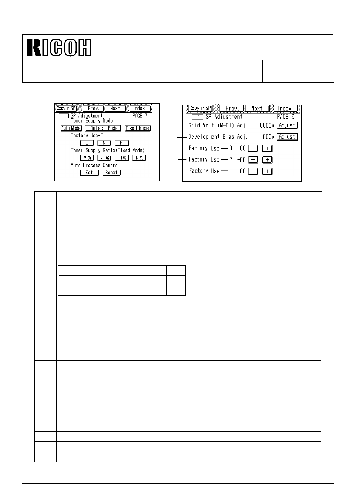
SP ADJUSTMENT
❶
❷
❸
PAGE 7
❼
PAGE 8
❺
❻
❽
❹
A176M508.img
Item Function Note
Selects toner supply mode.
(See the process control section for
❶
details about each supply mode.)
Default: Auto Mode
Changes the toner supply level in auto
and detect toner supply mode.
Default: N
Toner Supply level L N H
❷
Toner Supply Co-effcient x 0.3 x 0.5 x 1.0
Max. Toner Supply Ratio 30% 30% 60%
❾
Select "Auto Mode" in the field.
Select "N" in the field.
A176M509.img
Changes the toner supply ratio in fixed
❸
toner supply mode. Default: 4%
Enables and disables the auto process
control (VR, VL, VD corrections).
❹
(See the process control section for
details.) Default: Set
Inputs the grid bias voltage when auto
process control is disabled or after
❺
RAM is cleared (1 V/step).
Default: 870 V
Inputs the development bias voltage
when auto process control is disabled
❻
or after RAM is cleared (1 V/step).
Default: 220 V
Factory use only Do not change the setting in the field.
❼
Factory use only Do not change the setting in the field.
❽
Factory use only. Do not change the setting in the field.
❾
Be careful, there is no overtoning
protection system.
Normally select "Set". Select "Reset"
only to check if the cause of the
problem is related to process control or
not.
Enter the setting using the number
keys, then touch "Enter".
Enter the setting using the number
keys, then touch "Enter".
Page 3
Technical Bulletin No. RTB-002
SUBJECT: Service Remarks and Service Manual Correction DATE: 15,January
’97
PAGE: 1 of 3
PREPARED BY: H. K.
FROM: 1st Field Information Dept. QAC
CHECKED BY: T. Inoue
CLASSIFICATION:
Action Required
Troubleshooting
Retrofit Information
Revision of service manual
Information only
Other
MODEL:F401/F411/F421
1. Service Remarks (service manual page 4-5)
As one of the service remarks for the fusing unit, please add the following to your service
manual.
Symptom: A smeared image appears on the leading edge at about 10 mm on the 1st copy
at the machine installation.
Details: Silicone oil may slightly soak into the surface of the hot roller during machine
storage. The silicone oil may stick to the surface of the pressure roller when the hot roller
contacted the pressure roller at installation. The pressure roller may slip due to the oil
because the hot and pressure rollers are new. Therefore, a smeared image may appear
on the leading edge at about 10 mm on the 1st copy. This is because the hot roller is
rubbing the leading edge of the copy on the pressure roller.
Action: This symptom occurs only at the 1st copy after installation. Make sample copies
and make sure that the symptom does not recur after several copies.
2. Exposure Lamp for 230 V machines
Due to the use of the transformer, the same exposure lamps (AX520016 for the 50 CPM
machine, AX520020 for the 60/70 CPM machine) as for the 110 ~ 120 V version machines
are used for the 230 V machines. The exposure lamps for the 230 V machines in the
F400/F410/F420 are different from those for the 110 ~ 120 V machines in the
F400/F410/F420. Please note that the exposure lamps for the 230 V machines of
F401/F411/F421 cannot be installed in the F400/F410/F420 machines. Please see the
following table.
F401
(50/51 CPM)
AX520016 Yes No No Yes Yes No No No No
AX520020 No Yes Yes No No Yes No No No
AX520018 No No No No No No Yes Yes No
AX520022 No No No No No No No No Yes
F411
(60 CPM)
F421
(70 CPM)
F400
(45 CPM)
110~120V
F410
(55CPM)
110~120V
F420
(65 CPM)
110~120V
F400
(45 CPM)
230V
F410
(55 CPM)
230V
F420
(65 CPM)
230V
Yes : Can be used.
No : Cannot be used.
Page 4
Technical Bulletin No. RTB-002
SUBJECT: Service Remarks and Service Manual Correction DATE: 15,January
’97
PAGE: 2 of 3
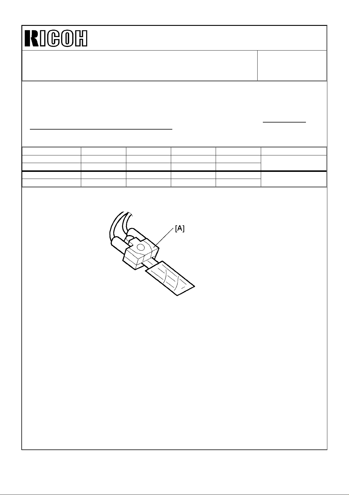
3. Fusing Thermistor Replacement (service manual page 5-94) and PM item (service
manual 4-55 and 4-60)
We found that if silicone oil is applied at the point where the thermistor comes in contact
with the hot roller, this may result in peeling of the film on the thermistor. Do not apply
silicone oil to the hot roller thermistor [A]. The hot roller thermistor PM action has been
revised. Please see the following table.
EM 120K 240K 360K NOTE
Incorrect Suitable solvent.
Fusing Thermistor
Correct Replace if necessary.
Fusing Thermistor I I I
C C C
Refer to NOTE 6
Page 5
Technical Bulletin No. RTB-002
SUBJECT: Service Remarks and Service Manual Correction DATE: 15,January
’97
PAGE: 3 of 3
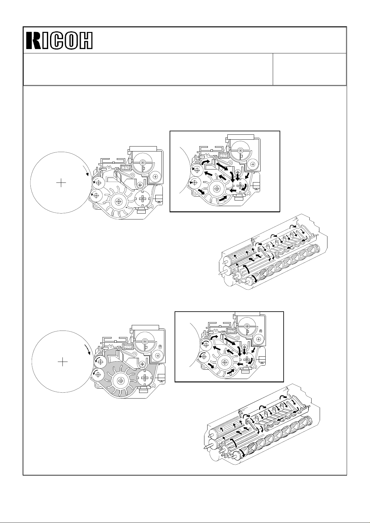
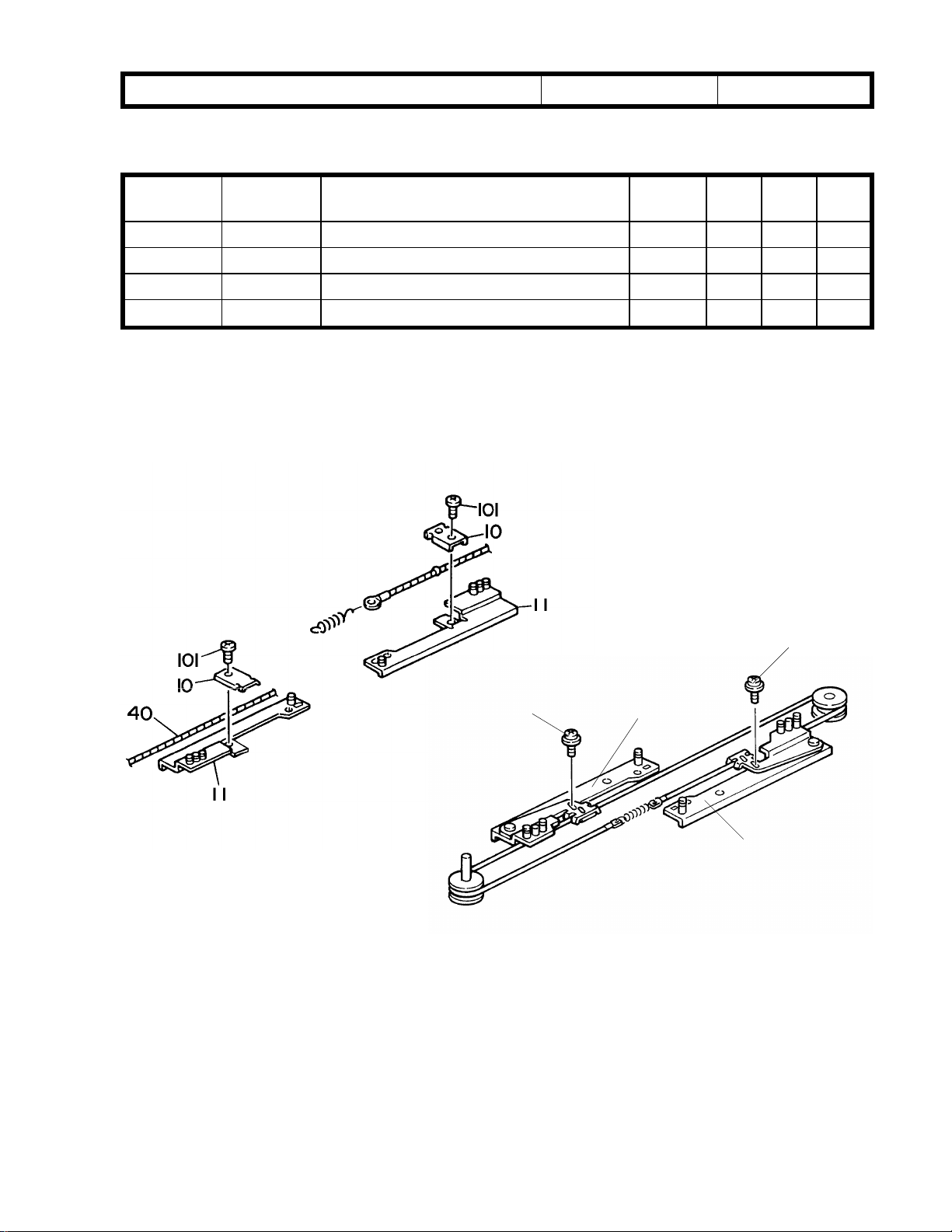
4. Illustration Correction for the Paddle Roller (service manual page 2-46 and 2-48)
The illustrations for the paddle roller on page 2-46 and 2-48 are incorrect. Please correct
your service manuals as shown below.
Incorrect
Correct
2 - 46
2 - 48
2 - 46
2 - 48
Page 6
RICOH Technical Bulletin PAGE: 1/1
Model: F401/411/421 Date: 15-Mar-97
Subject: Light Copies (2) Prepared by: F.Noguchi
From: QAC 1st Field Information Dept. Checked by: T. Inoue
Classification:
Troubleshooting
Mechanical
Paper path
Other ( )
Part information
Electrical
Transmit/receive
Action required
Service manual revision
Retrofit information
No: 003
SYMPTOM
When making multiple copies (100-300) of an original with a high image area ratio
(example:Test Chart=35%), there is a drop in image density.
CAUSE
The toner supply level is less than the toner consumption level.
SOLUTION
The toner supply ratio has been changed with the ROM modification listed below.
Please replace the ROMs as necessary.
Old New
L N H L N H
Toner Supply Coefficient x0.3 x0.5 x1.0 x0.5 x1.0 x1.5
Max Toner Supply Ratio 30% 30% 60% 30% x60% x60%
ROM ~A1755151J ~A1755151K
~A1755153J ~A1755151K
Note:
1. If the toner supply ratio has been changed from “N” to “H” (SP Adjustment, page 7,
Factory Use-T) as described in RTB-001, please return the setting to “N” when the new
ROMs are installed.
2. If dirty background appears in non-image areas during toner supply, please change the
toner supply ratio from “N” to “L”.
3. If the slitter in the Toner Supply Unit is removed, the seal may get caught in the slitter
when the slitter is reattached. Please exercise caution to prevent this from happening.
<Cut-in Serial Numbers>
Will be provided as soon as it becomes available.
Page 7

RICOH Technical Bulletin PAGE: 1/9
Model: F401/F411/F421/Cardinal Bird Date: 15-Jun-97
Subject: Cardinal Bird Information Prepared by: H. Kobayashi
From: QAC 1st Field Information Dept.
Classification:
Troubleshooting
Mechanical
Paper path
Other ( )
Part information
Electrical
Transmit/receive
Action required
Service manual revision
Retrofit information
No: 4
1. Introduction
In addition to F401 (50 cpm machine), another 50 cpm machine (Cardinal Bird) is required
to increase our MIF in the high speed segment. Cardinal Bird is designed and produced
with re-manufactured parts. Ricoh collects the used F400 series machines from the
Japanese domestic market. A Ricoh factory will disassemble the collected machines,
select the re-usable parts from the disassembled parts, and assemble the machines as
new products using the selected re-usable parts and the new parts. (All the PM parts are
new parts.) As a result, the Cardinal Bird is service-friendly because the machine
configuration and PM parts are very similar to the F401 series.
Page 8
RICOH Technical Bulletin PAGE: 2/9
Leveling feet
No. 17
Model: F401/F411/F421/Cardinal Bird Date: 15-Jun-97
No: 4
2. Sales/Service remarks
In addition to the F401/F411/F421 sales/service remarks, the following remarks are added
as the Cardinal Bird sales/service remarks because the Cardinal Bird has remanufactured parts.
No. Item Category Details Action to be
taken/Remarks
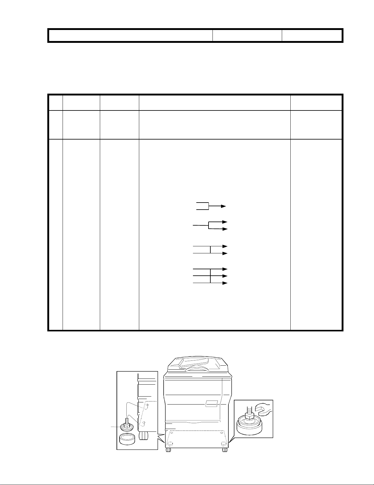
17 Leveling
feet
18 Old parts
before
modification
A, B This machine has a re-manufactured bottom plate.
There are two types of bottom plate. One has two
leveling feet installed. The other has four leveling
feet.
B a) This machine has re-manufactured parts. Among
these parts, there will be some sets of old parts
before modification. These old parts are not often
replaced in the field. However, the old part should
be replaced, together with new ones, as a set if
the old part is replaced in the field because the
old parts were modified as a set.
Please refer to the following F400 MBs.
A0964718
A0964715
A0964715 (MB34)
Please accept
this.
Please accept
replacement of
the old parts
together with the
new parts as a
set.
A0964883
A0965743 A0975473 (MB111)
A0961816 A0971816
A0966303 A1766303 (MB139)
A0966338 A1766338
A0966337 A1766337
b) The jogger sensor bracket has been added for
factory purposes only. There are two types of
duplex unit.
Non-jogger sensor bracket type and jogger sensor
bracket type
A0964762 (Newly added) (MB95)
A0964887 (MB95)
A0964886
Please note that
there are two
types of duplex
unit.
Page 9
RICOH Technical Bulletin PAGE: 3/9
#11
Model: F401/F411/F421/Cardinal Bird Date: 15-Jun-97
No: 4
- MB34 -
Old part
number
A0964718 Wire Fixing Plate
A0964715 A0964715 Jogger Support Plate
04340080B Philips Tapping Screw - M4 x 8
New part
number
09514008B Philips Screw with Washer - M4 x 8
Description Qty Int Page Index
2 → 0
2 → 2
n → n-2
n → n+2
X/ 77 10
/O 77 11
X/ 77 101
/O 77 103
To facilitate manufacturing, the wire fixing plate has been mounted on the jogger support
plate. The part number of the jogger support plate is still the same because the old part
was never shipped out as a service part.
#103
#103
#11
Page 10
RICOH Technical Bulletin PAGE: 4/9
# 44
# 108
**
Model: F401/F411/F421/Cardinal Bird Date: 15-Jun-97
No: 4
- MB95 -
Old part
number
A0964883 A0964887 Duplex Lock Lever
A0964894 A0964895 Duplex Harness Bracket
New part
number
A0964762 Jogger Sensor Bracket
A0964886 Duplex Lock Arm
04340080B Philips Tapping Screw - M x 8
Description Qty Int Page Index
0 1
0 1
1 1
1 → 1
n → n+2
*New index number
73 *45
73 *44
X/X 73 3
X/X 75 26
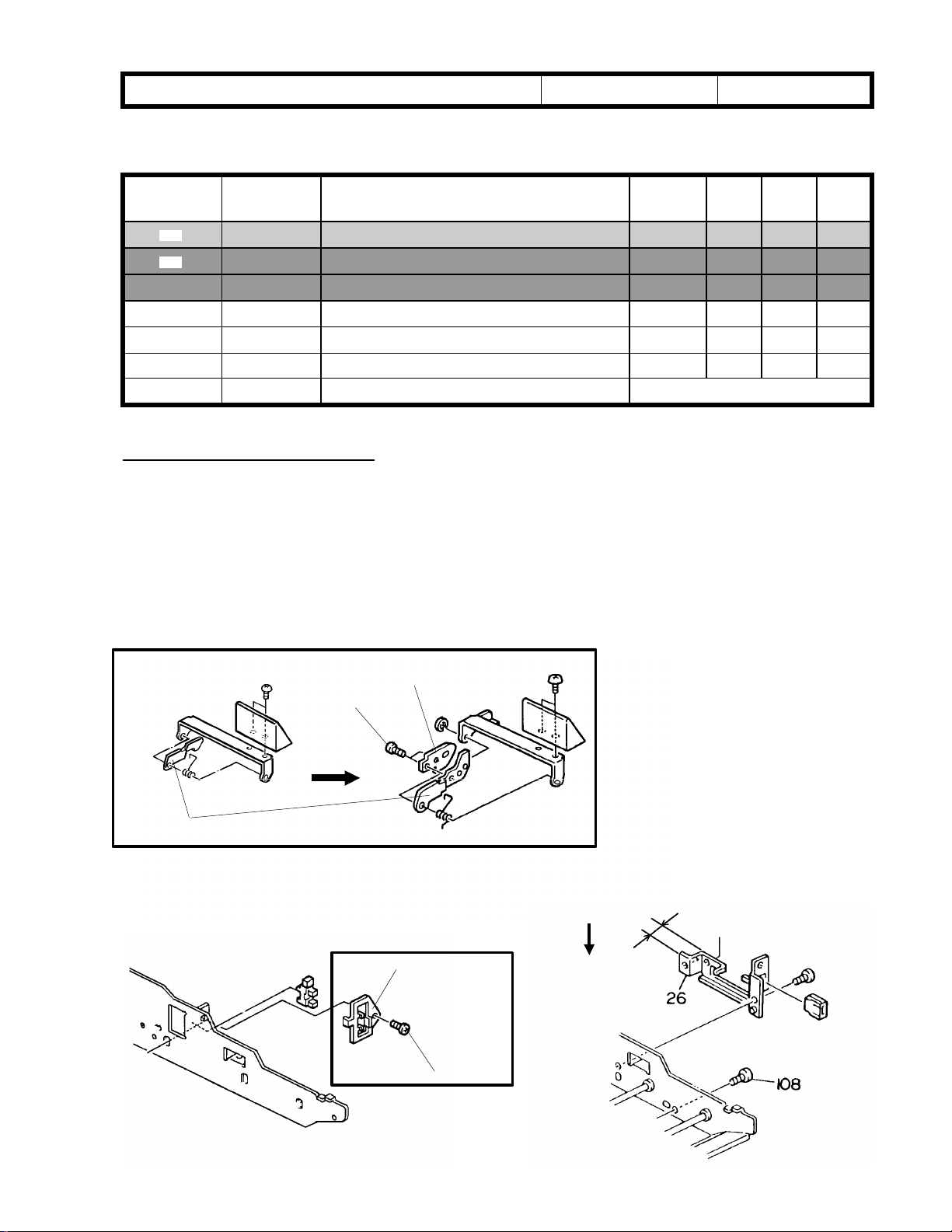
DETAILS OF MODIFICATION
1. The mechanism for the duplex side registration adjustment, which was originally
designed for other models, has been incorporated into the F400/F410/F420. By
changing the position of # 44 against # 3 (one screw, # 108), side registration can be
adjusted ±1.5 mm. At the same time, the height of the duplex harness bracket (# 26)
has been increased by 2 mm to ensure the engagement of the duplex connector.
2. The jogger sensor bracket (# 45) has been added for factory use only.
# 3 Duplex Lock
11.5 mm
# 45
13.5 mm
*
# 101
Page 11
RICOH Technical Bulletin PAGE: 5/9
Model: F401/F411/F421/Cardinal Bird Date: 15-Jun-97
- MB111 -
Old part
number
A0961921 A0971921 Scanner Drive Shaft C
A0961925 A0971925 Front Wire Pulley C
A0071920 A0971746 Exposure Glass Cushion C
A0965473 A0975473 Outer Optics Harness C
11026245 11026283 Connector - 2P
11026246 11026284 Connector - 3P
11026247 11026285 Connector - 4P
11026260 11026285 Connector - 3P
Old part
number
A0961766 A0971766 Lens Slider C
A0961816 A0971816 Sensors Bracket - Lens Position C
A0961994 A0971994 Filter Holder C
AA150336 AA150378 Front Shelding Mylar C
A0961766 A09771766 Lens Slider C
AC051013 AC051016 Lens Guide Red - X C
AC051015 AC051017 Guide Red - 3rd Scanner C
New part
number
A0971698 Scanner Cushion C
New part
number
Description Rank Qty Int Page Index
Description Rank Qty Int Page Index
1 → 1
1 → 1
0 → 2
4 → 4
1 1
1 → 1
1 → 1
1 → 1
1 → 1
1 → 1
1 1
1 → 1
1 → 1
1 → 1
1 → 1
1 → 1
No: 4
O/O 23 1
O/O 23 2
27 28
O/O 19 15
X/X 23 31
O/X 23 117
O/X 23 118
O/X 23 120
O/X 23 119
O/O 31 11
X/X 23 21
O/O 21 11
O/O 31 7
O/O 31 11
O/X 25 2
O/X 29 25
Page 12

RICOH Technical Bulletin PAGE: 6/9
28
Model: F401/F411/F421/Cardinal Bird Date: 15-Jun-97
DETAILS OF MODIFICATION
The parts listed on the front pages have been modified for part standardization with other
models.
- Supplemental explanation for outer optics harness The sensor bracket has been modified as shown below right. At the same time, four
relay connectors (index # 118 through # 120), which have been changed from the
type attachable in the bracket holes to the flat type, have been incorporated into the
outer optics harness.
Sensor Bracket
No: 4
# A0975473
Scanner Cushion
Page 13

RICOH Technical Bulletin PAGE: 7/9
Model: F401/F411/F421/Cardinal Bird Date: 15-Jun-97
- MB139 -
Due to parts standardization, the following parts have been changed.
Since the location of the position sensor bracket on which the separation roller stay is
installed has been moved 5 mm towards the rear, please replace the 3 parts listed above
at the same time. Also because the old parts were molded, they will no longer be
available.
Old part
number
A096 6303 A176 6306 Separation Roller Stay 3 - 3 X/X 39 44 *
A096 6338 A176 6338 Separation Guide 3 - 3 X/X 39 42 *
A096 6337 A176 6337 Paper Feed guide 3 - 3 X/X 39 14 *
The interchangeability is O/O as a set.
New part
number
Description Qty Int Page Index Note
No: 4
-Old-
12.5 mm
-New-
7.5 mm
-Old-
Blue circle
(for Cardinal Bird only)
Page 14

RICOH Technical Bulletin PAGE: 8/9
550
550
3,500
550
storage
550
3,500
550
Model: F401/F411/F421/Cardinal Bird Date: 15-Jun-97
No: 4
3. Service manual
The Cardinal Bird service manual, which is to be inserted into the F401/F411/F421
service manual, will be prepared.
4. Parts catalog
The Cardinal Bird parts catalog, which is the F401/F411/F421 copier parts catalog and
which can be used as the F401/F411/F421/Cardinal Bird copier parts catalog, will be
prepared.
5. Machine configuration
There are two types of mainframe.
A220 - (10, 17, 20, 29,:) copiers
Three 550-sheet paper trays
Optional 3,500-sheet large capacity tray
A220 - (22: china) copiers
Two 550-sheet paper trays
storage tray
Optional 3,500-sheet large capacity tray
Page 15

RICOH Technical Bulletin PAGE: 9/9
Model: F401/F411/F421/Cardinal Bird Date: 15-Jun-97
No: 4
6. Transport Guide of the lower drum unit
To ensure paper transport, the 60/70 cpm type of transport guides are added to the pickoff pawl section.
7. PSU
As a re-manufactured PSU (AZ240019:100/115 V) is used for this machine, a transformer
has been added to the 220/230/240 V versions. Please note that the PSU (AZ240021) for
the 220/230/240 V versions of the F400/F410 cannot be used for the 220/230/240 V
versions of the Cardinal Bird
A220 -10,-17
(Cardinal)
AZ240019 Yes Yes Yes No
AZ240021 No No No Yes
Yes: Can be used.
No: Cannot be used.
A220 -20, -22, -29
(Cardinal)
F400/F410
(U.S.A.)
F400/F410
(220/230/240 V)
Page 16

RICOH Technical Bulletin PAGE: 1/1
Model: F401/411/421/Cardinal Date: 31-Aug-97
Subject: ON/OFF Control vs Phase Control Prepared by: H.K.
From: QAC 1st Field Information Dept.
Classification:
We have found a mistake in the service manual on page 2-98 (Fusing Lamp Control).
Please correct your service manual as follows:
Troubleshooting
Mechanical
Paper path
Other ( )
Part information
Electrical
Transmit/receive
Action required
Service manual revision
Retrofit information
No: 5
Incorrect
By cutting JP501 on the optics control board, the control mode changes to another mode.
Correct
The fusing temperature control mode cannot be changed on the European version
machines. The electrical noise margin is not enough to meet the European Standards for
the European version for F401/F411/F421. The mode can be changed on the other
version machines as follows.
F401/F411/Cardinal
JP501 U.S.A. and Asia versions European version
Cut On-off control On-off control
Not cut Phase control On-off control
F421
DPS501 U.S.A. and Asia versions European version
ON On-off control On-off control
OFF Phase control On-off control
For reference, the mode change for the F400 series (all versions) is as follows:
F400/F410/F420
JP501 U.S.A. and Asia versions European version
Cut On-off control Phase control
Not cut Phase control On-off control
Page 17

T
Model:
LCT for F401/411/421
echnical
ulletin
B
Date:
15-Oct-97
No:
PAGE: 1/2
6
Subject:
From:
Classification:
LCT Jam
QAC Field Information Dept.
Troubleshooting
Mechanical
Paper path
Other ( )
Part information
Electrical
Transmit/receive
Prepared by:
Action required
Service manual revision
Retrofit information
M.Kitajima
SYMPTOM
Paper jams occur when feeding from the LCT. The characteristics of this problem
are as follows.
1. Constant jams from LCT installation onwards.
2. Non-paper feed jams.
3. Sometimes there is a crease in the central part of the leading edge of the paper,
which results in skewing.
CAUSE
There is a burr in the welded area of the entrance guide plate in the LCT paper feed
section.
SOLUTION
When this problem occurs in machines in the field or when installing an LCT on which the
countermeasure has not been implemented, please check for burrs in the following
manner.
1. Remove the paper feed unit of the LCT.
2. Carefully insert a piece of OHP sheet along the entrance guide plate as shown.
OHP Sheet
Burr
Page 18

T
Model:
3. If the OHP gets scratched, the burr on the entrance guide plate should be filed away in
4. If the OHP does not get scratched, there is no burr. Another cause needs to be found.
LCT for F401/411/421
the manner shown.
echnical
ulletin
B
Date:
15-Oct-97
No:
PAGE: 2/2
6
Cut-in Serial Number
The proper part has been included in machines with the following serial numbers.
MODEL
NAME
NRG RT34 120/ 60 U. S. A. , Canada
Savin RT34 120/ 60 U. S. A. A609 - 15 5A47470001
Ricoh RT34 120/ 60 U. S. A. A609 - 17 A7077480009
NRG RT34 230/ 50 Europe etc. A609- 22 AF17450001 AF17450002,006,009,
Infotec RT34 230/ 50 Europe A609 - 26 3K84770029
Ricoh RT34 230/ 50 Europe, Asia etc. A609 - 27 A7077470683
V/ Hz DESTINATION CODE SERIAL
NUMBER
A609 - 10 AF07480001
etc.
Exception
A7077480010,012∼189,
275∼276
011∼012,014∼017,023,025
3K84770030∼034,036∼037,
039,044,046∼048
A7077470684,695∼697,
700∼714,717,719∼720,731,
735,744∼802
Page 19

T
Model:
F401/F411/F421
echnical
B
ulletin
Date:
31-Jan-98
No:
PAGE: 1/3
7
Subject:
From:
Classification:
This bulletin is to inform you of the modifications applied to the L-version ROMs.
ROM Part Number
Old New
A1755151K A1755151L
A1755153K A1755153L
1. Energy Star (North America version)
A. Auto-Off Mode Settings
The range of settings for Auto-off Mode has been changed from “1 to 120 minutes”
to “1 to 240 minutes”. The default will not change (90 minutes).
B. Auto-off Release
The weekly timer has been made available. Note that the Off key is displayed on the
screen when setting the time for Auto-off mode, but this key can not be used.
Software update information
QAC Field Informat ion Dept.
Troubleshooti ng
Mechanical
Paper path
Other ( )
Part information
Electrical
Transmit/receive
Prepared by:
Action required
Service manual revision
Retrofit information
M.Kitajima
2. The following symptoms have been corrected.
1. When the following procedure is done, the data for Erase Center/Border is cleared.
① Erase Center/Border Reduce/Enlarge
② Interrupt
③ Interrupt Release
④ Edit Image
⑤ Press Erase Center/Border key
This symptom is duplicated when using the store Program Recall/Program
Interrupt /Interrupt Release key.
2. The duplex jam caused by poor paper stacking in the duplex tray may occur in the
following condition .
• DF version
• Centering mode
• A4 sideways copy paper
• 50 set(s) of copy(ies)
• Double-sided Mode
The jam occurs in the 70 cpm machine more often than in the 60 cpm machine.
Page 20

T
Model:
MODEL
NAME
Ges 2651
NSA 4651
SVN 9500
Savin 9500 120/ 60 U. S. A. A175 - 15 A175 - 15 4A77480002
Ricoh FT7650 120/ 60 U. S. A. A175 - 17 A175 - 17 A7037470373
Ricoh FT7650 110/ 60 Taiwan A175 - 19 A7037070226
Spirio 5000 230/ 50 Korea A175 - 21 A7037070176
Ges 2651
NSA 4651
Rex 8651
Infotec
5501DZ
Ricoh FT7650 230/ 50 Europe, etc. A175 - 27 A7037080130
Ricoh FT7650 230/ 50 Asia, etc. A175 - 29 A7037070001
Ges 2760
NSA 4760
SVN 9600
Savin 9600 120/ 60 U. S. A. A176 - 15 A176 - 15 4A87470001
Ricoh FT7660 120/ 60 U. S. A. A176 - 17 A176 - 17 A7047470001
Ricoh FT7660 110/ 60 Taiwan A176 - 19 A704802xxxx
NSA 4760
Ges 2760
Ricoh FT7660 230/ 50 Asia, etc. A176 - 29 A7047070001
F401/F411/F421
V/ Hz DESTINATION CODE SERIAL
120/ 60 U. S. A. , Canada,
etc.
230/ 50 Europe, etc. A175 - 22 AC47070001
230/ 50 Europe A175 - 26 3K10770001
120/ 60 U. S. A. , Canada,
etc.
230/ 50 Asi a, etc. A176 - 22 AD27070001
echnical
JAPAN PRODUCTION REI PRODUCTION
A175 - 10 A175 - 10 A C67470139
A176 - 10 A176 - 10 A D47470002
B
NUMBER
ulletin
Date:
31-Jan-98
No:
CODE SERIAL
PAGE: 2/3
7
NUMBER
RPL PRODUCTION
MODEL
NAME
Ges 2651
NSA 4651
Rex 8651
Infotec
5501DZ
Ricoh FT7650 230/ 50 Europe, etc. A175 - 67 A7038210001
V/ Hz DESTINATION CODE SERIAL
NUMBER
230/ 50 Europe, etc. A175 - 62 AC48210001
230/ 50 Europe A175 - 66 3K12180001
Page 21

T
Model:
MODEL
NAME
NSA 4770
SVN 9700
Ges 2770
Savin 9700 120/ 60 U. S. A. A177 - 15 A177 - 15 5A67470001
Ricoh FT7670 120/ 60 U. S. A. A177 - 17 A177 - 17 A7107470047
spirio 7000 230/ 50 KOREA A177 - 21 A7107080131
NSA 4770
Ges 2770
Ricoh FT7670 230/ 50 Asia, etc. A177 - 29 A7107070001
Ges 2660
NSA 4660
REX 8660
Infotec
5601DZ
Ricoh FT7660 230/ 50 Europe, etc. A191 - 27 A7057070001
Ges2670
NSA 4670
Rex 8670
Infotec
5701DZ
Ricoh FT7670 230/ 50 Europe, etc. A192 - 27 A7117070001
F401/F411/F421
V/ Hz DESTINATION CODE SERIAL
120/ 60 U. S. A. , Canada,
etc.
230/ 50 Asi a, etc. A177 - 22 AE07070001
230/ 50 Europe, etc. A191 - 22 AC87110001
230/ 50 Europe A191 - 26 3K20770001
230/ 50 Europe, etc. A192 - 22 AD67070001
230/ 50 Europe A192 - 26 3K30770001
echnical
JAPAN PRODUCTION REI PRODUCTION
A177 - 10 A177 - 10 A E27470001
B
NUMBER
ulletin
Date:
31-Jan-98
No:
CODE SERIAL
PAGE: 3/3
7
NUMBER
RPL PRODUCTION
MODEL
NAME
Ges 2660
NSA 4660
REX 8660
Infotec
5601DZ
Ricoh FT7660 230/ 50 Europe, etc. A191 - 67 A7058210001
V/ Hz DESTINATION CODE SERIAL UMBER
230/ 50 Europe, etc. A191 - 62 AC88210001
230/ 50 Europe A191 - 66 3K22180001
Page 22

T
echnical
B
ulletin
RTB Correction
Reissue date:
The serial numbers for REI production have been added in bold italics.
Model:
F401/411/421
28-Feb-99
Date:
15-Jul-98
No:
PAGE: 1/4
8
Subject:
From:
Classification:
An SP mode has been added for the F421 (70 CPM) to reduce the chances of stacking
problems in the duplex tray when non-recommended paper or paper with a large curl is
used.
Software Update Information
QAC Field Information Dept.
Troubleshooting
Mechanical
Paper path
Other ( )
ROM Part Number
Old New
A1755151L A1755151M
A1755153L A1755153M
Part information
Electrical
Transmit/receive
Prepared by:
Action required
Service manual revision
Retrofit information
F.Noguchi
SYMPTOM
1. Duplex tray stack jams
2. No-feed paper jams during duplex unit paper feed
CAUSE
Stacking problems in the duplex tray when paper with a large curl (more than 10 mm: not
within specifications) is used.
SOLUTION
Since this is a paper-related problem, please select #3 or #4 in the SP Mode as
necessary.
Please refer to the SP Mode table on the attached sheet.
Note:
The cut-in serial number list has been attached for your reference.
(REI: under investigation)
This ROM is used for the F401 series but this SP Mode can function on the F421
only.
Page 23

T
Model:
F401/411/421
echnical
B
ulletin
Date:
15-Jul-98
③,④
No:
PAGE: 2/4
8
Item Function Note
①
②
③
④
Note:
on the paper and will improve the stacking of curled paper in the duplex unit.
Selects whether the Taiwanese paper
sizes (8k, 16k) are detected in the 2
tray or not.
Selects the machine version. 50 CPM version in France…..1
Selects the positioning roller ON
timing.
Selects the paper feed interval from
the paper tray for the front side of the
copy in the duplex mode.
Either ③ or ④ can be used to increase the time the inverter weight presses down
1: Please do not use this with thin paper that is less than 80g/m2.
∗
2: Use of setting 2 (397ms) is recommended.
∗
Please note that ③ and ④ cannot be used at the same time.
nd
European and Asian versions only
Not detected: 0 (Default)
8k, 16k, paper sizes are detected: 1
Others (Default)…………….. 0
80 ms………………………….1
150 ms (Default)…………… 0
397 ms…………………..…….2
368 ms (Default)……………...0
1
∗
2
∗
Page 24

T
Model:
MODEL
NAME
Ges 2651
NSA 4651
SVN 9500
Savin 9500 120/ 60 U. S. A. A175 - 15 A175 - 15
Ricoh FT7650 120/ 60 U. S. A. A175 - 17 A175 - 17
Ricoh FT7650 110/ 60 Taiwan A175 - 19 A7038010113
Spirio 5000 230/ 50 Korea A175 - 21 A703802xxxx
Ges 2651
NSA 4651
Rex 8651
Infotec
5501DZ
Ricoh FT7650 230/ 50 Europe, etc. A175 - 27 A7038020312
Ricoh FT7650 230/ 50 Asia, etc. A175 - 29 A7038010001
Ricoh FT7650 230/50 China A175 - 69 A7038050001
Ges 2760
NSA 4760
SVN 9600
Savin 9600 120/ 60 U. S. A. A176 - 15 A176 - 15
Ricoh FT7660 120/ 60 U. S. A. A176 - 17 A176 - 17
Ricoh FT7660 110/ 60 Taiwan A176 - 19 A7048050002
NSA 4760
Ges 2760
Ricoh FT7660 230/ 50 Asia, etc. A176 - 29 A7048010001
Ricoh FT7660 230/50 China A176 - 69 A7048050001
F401/411/421
V/ Hz DESTINATION CODE SERIAL
120/ 60 U. S. A. , Canada,
etc.
230/ 50 Europe, etc. A175 - 22 AC48010001
230/ 50 Europe A175 - 26 3K1028xxxx
120/ 60 U. S. A. , Canada,
etc.
230/ 50 Asia, etc. A176 - 22 AD28010001
echnical
JAPAN PRODUCTION REI PRODUCTION
A175 - 10 A175 - 10
A176 - 10 A176 - 10
B
NUMBER
ulletin
Date:
15-Jul-98
CODE SERIAL
No:
8
NUMBER
AC68420001
4A78410204
A703841397
AD48420001
4A88420001
A7048420001
PAGE: 3/4
RPL PRODUCTION
MODEL
NAME
Ges 2651
NSA 4651
Rex 8651
Infotec
5501DZ
Ricoh FT7650 230/ 50 Europe, etc. A175 - 27 No implementation
V/ Hz DESTINATION CODE SERIAL NUMBER
230/ 50 Europe, etc. A175 - 62 No implementation
230/ 50 Europe A175 - 66 No implementation
Page 25

T
Model:
MODEL
NAME
NSA 4770
SVN 9700
Ges 2770
Savin 9700 120/ 60 U. S. A. A177 - 15 A177 - 15
Ricoh FT7670 120/ 60 U. S. A. A177 - 17 A177 - 17
spirio 7000 230/ 50 KOREA A177 - 21 A710802xxxx
NSA 4770
Ges 2770
Ricoh FT7670 230/ 50 Asia, etc. A177 - 29 A7108010001
Ricoh FT7670 230/50 China A177 - 69 A7108030001
Ges 2660
NSA 4660
REX 8660
Infotec
5601DZ
Ricoh FT7660 230/ 50 Europe, etc. A191 - 27 A705802xxxx
Ges2670
NSA 4670
Rex 8670
Infotec
5701DZ
Ricoh FT7670 230/ 50 Europe, etc. A192 - 27 A7118010001
F401/411/421
V/ Hz DESTINATION CODE SERIAL
120/ 60 U. S. A. , Canada,
etc.
230/ 50 Asia, etc. A177 - 22 AE08010001
230/ 50 Europe, etc. A191 - 22 AC88010001
230/ 50 Europe A191 - 26 3K2028xxxx
230/ 50 Europe, etc. A192 - 22 AD68010001
230/ 50 Europe A192 - 26 3K30180001
echnical
JAPAN PRODUCTION REI PRODUCTION
A177 - 10 A177 - 10
B
NUMBER
ulletin
Date:
15-Jul-98
CODE SERIAL
No:
8
NUMBER
AE28430001
5A68420001
A7048420001
PAGE: 4/4
RPL PRODUCTION
MODEL
NAME
Ges 2660
NSA 4660
REX 8660
Infotec
5601DZ
Ricoh FT7660 230/ 50 Europe, etc. A191 - 67 No implementation
V/ Hz DESTINATION CODE SERIAL UMBER
230/ 50 Europe, etc. No implementation
230/ 50 Europe A191 - 66 No implementation
Page 26

T
Model:
F401/411/421
echnical
B
ulletin
Date:
31-Jul-98
No:
PAGE: 1/2
9
Subject:
From:
Classification:
As per field request, the built-in LCT lift wire replacement procedure is now described as
follows (built-in LCT version only):
Built-in LCT Lift Wire
QAC Field Information Dept.
Troubleshooting
Mechanical
Paper path
Other ( )
Part information
Electrical
Transmit/receive
Prepared by:
Action required
Service manual revision
Retrofit information
H.Kobayashi
Built-in LCT Tray Lift Wire Replacement
A229R677.WMF
[A]
[B]
A229R676.WMF
1. Remove the built-in LCT. (Refer to Paper Tray Removal.)
2. Remove the front cover [A] (4 screws, 1 connector, 3 hooks).
3. Remove the 3rd tray lift motor unit [B] (4 screws, 1 connector).
Page 27

T
Model:
F401/411/421
echnical
[B]
[A]
B
ulletin
Date:
31-Jul-98
No:
PAGE: 2/2
9
[C]
[C]
A229R679.WMF
1. Remove the spring [A].
2. Remove the wire [B].
3. Wind the end of the new wire with no marking around the tray lift drive pulley [C] in the
correct direction, as shown. (①).
4. Route the wire with the ball as shown (②, ③, ④, ⑤, ⑥, ⑦, and ⑧).
5. Wind the end of wire with marking around the tray lift drive pulley in the correct
direction, as shown (⑨).
6. Put the spring back on the wire tension bracket.
7. Wind the new tray lift wire for the other side as well.
Page 28

T
Model:
F401/411/421
echnical
B
ulletin
Date:
31-Aug-98
No:
PAGE: 1/2
10
Subject:
From:
Classification:
Medaka (Short black lines)
QAC Field Information Dept.
Troubleshooting
Mechanical
Paper path
Other ( )
Part information
Electrical
Transmit/receive
Prepared by:
Action required
Service manual revision
Retrofit information
M.Kitajima
SYMPTOM
Medaka (short black lines) on copies.
CAUSE
If a large number of duplex copies is made, the temperature in the machine will rise
because the paper that has passed through the fusing section increases the amount of
heat. Paper dust may also cause this problem but the degree will vary depending on the
type of paper used. The mixture of toner and paper dust is attracted to the drum surface.
Since the temperature in the machine is higher, this mixture becomes softer and makes it
more difficult for the cleaning blade and brush to completely remove it from the drum.
SOLUTION
Install the lubricant bar on an individual basis if Medaka appear.
Before installing it, the developer should be replaced. Also, the drum should be cleaned
completely or replaced.
Installation Procedure
1. Prepare the lower drum unit
∗This part is only installed in the F411 and F421 in the Japan version of the machine.
2. Replace the lower drum unit with
3. Change the VP value from 0V (default ) to –
1 (PAGE 8, Item 8).
Since the ID sensor pattern becomes lighter as a result of the lubrication, the toner
∗
concentration in the developer becomes much higher, causing the toner scattering or dirty
background.
(P/N: A1763510)
P/N A1763510
❺
❻
❼
❽
❾
.
.
40V
using the SP Mode adjustment
Page 29

T
[B]
Model:
PM parts are newly added, and they should be replaced every 120K copies. Both parts
are included in the lower drum unit.
F401/411/421
echnical
B
ulletin
Date:
31-Aug-98
No:
PAGE: 2/2
10
A1763515
A1763522
The replacement procedure for the lubricant bar is as follows.
1. Remove the cleaning release lever
2. Remove the spring
3. Remove the cam gear-35Z
4. Remove the cleaning brush bushing
5. Remove the cleaning blade bracket ass’y
6. Remove the lubricant bar ass’y
7. Remove the lubricant bar seal
8. Remove the stopper
Lubricant Bar
Lubricant Bar Seal
[B].
[E]
[C]
[A]
(1 screw).
[C]
(1 E-ring, spacer M-6).
[D]
(1 screw).
[E].
[F]
(3 screws).
[G]
(3 screws) and replace it.
[H]
and replace the lubricant bar
[A]
[I].
[D]
[F]
[G]
[I]
[H]
Page 30

RICOH Technical
Bulletin
Model: F401/411/421, Cardinal Bird Date: 31-Oct-98 No.: 11
PAGE: 1/3
Subject:
From:
Development Entrance Seal Replacement
GTS and S Field Information Dept.
Classification:
Troubleshooting
Mechanical
Paper path
Other ( )
Part information
Electrical
Transmit/receive
Prepared by:
Action required
Service manual revision
Retrofit information
F. Noguchi
This is to inform about a problem that could occur in theory.
This problem, however, will not occur at an early stage but may develop as the machine is
used over a long period of time. This problem may only occur when the photoconductor
gap (PG) is at the narrowest setting (0.65 mm) and the doctor gap is at the widest setting
(0.70 mm). This PG/DG setting does not exist in production machines as far as checked in
the factory but is still within the adjusting range.
- Problem -
The lower seal (straight; the upper seal is a loop) of the development unit entrance seal
ass'y (P/N A2293092) may get pinched between the developer and the drum if a large
amount of developer accumulates near the photoconductor gap (PG). The seal may be
pulled out of position by the friction caused by the rotation of the drum. In the worst case,
the seal would peel off.
Upper seal
Lower seal
Drum
PG
Developer accumulation
DG
Upper development roller
- Cause -
The width of the lower seal is 18 mm, which may be too much. This problem does not
occur with the previous entrance seal ass'y (P/N A0963103) that has a width of 17mm.
- Countermeasure -
The width of the lower seal will be returned to the original 17 mm from 18 mm. Though the
17 mm lower seal may wrap up, the function of this part is not adversely affected. The part
number of the new development unit entra nce s eal ass'y will be A2293091.
Page 31

RICOH Technical
Bulletin
Model: F401/411/421, Cardinal Bird Date: 31-Oct-98 No.: 11
- Targeted Machines -
PAGE: 2/3
Model Code Brand Destination Total Sub-
Total
F401
F411
F421
F421
Cardinal
Bird
A175-19 Ricoh Taiwan 242 75
A175-22 NRG Europe, etc. 10 10 AC48070001 thru AC48070010
A175-29 Ricoh Asia, Oceania 90 90 A7038070021 thru A7038070110
A175-69 R ic oh Hong Kong,
China
A176-19 Ricoh Taiwan 155 50
A176-29 Ricoh Asia, Oceania 81 41
A176-69 R ic oh Hong Kong,
China
A177-29 Ricoh Asia, Oceania 57 24
A177-69 R ic oh Hong Kong,
China
A192-22 NRG Europe, etc. 70 30
A192-26 Infotec Europe, etc. 65 40
A192-27 Ricoh Europe, etc. 42 32
A220-17 Ricoh USA, Canada 23 23 A7598070001 thru A7598070023
34 20
8 2
4 1
Serial Numbers
A7038070111 thru A7038070185
167
A7038080015 thru A7038080181
A7038070001 thru A7038070020
14
A7038080001 thru A7038080014
A7048070044 thru A7048070093
105
A7048080047 thru A7048080151
A7048070003 thru A7048070043
40
A7048080007 thru A7048080046
A7048070001 thru A7048070002
6
A7048080001 thru A7048080006
A7108070002 thru A7108070025
33
A7108080004 thru A7108080036
A7108070001
3
A7108080001 thru A7108080003
AD68070001 thru AD68070030
40
AD68080001 thru AD68080040
3K30780001 thru 3K30780040
25
3K30880001 thru 3K30880025
A7118070001 thru A7118070032
10
A7118080001 thru A7118080010
Page 32

RICOH Technical
Model: F401/411/421, Cardinal Bird Date: 31-Oct-98 No.: 11
- Replacement Procedure -
Bulletin
PAGE: 3/3
1. Remove the 2 screws
2. While pulling on the lock clip
3. Install a new entrance seal ass’y.
[A]
that secure the entrance seal.
[B]
, slip off the entrance seal ass’y
[A]
[C]
[C]
.
[B]
Page 33

T
Reissued: 30-Apr- 99
echnical
B
ulletin
PAGE: 1/1
Model:
F401/411/421/C-Bird
Date:
15-Apr-99
No.:
RA175012a
RTB Correction
The items (cut-in serial number) in bold italics have been corrected.
Subject:
From:
Classification:
DJF Software Modification History
Technical Service Dept., GTS Division
Troubleshooting
Mechanical
Paper path
Other ( )
Part information
Electrical
Transmit/receive
DJF modifications and history are as follows.
Main ROM(A6105820) modification history
Suffix Description Cut-in Serial Number
C This ROM was used from the first production run. A610-15: A16060001
D To prevent original jams:
In the limitless mode, if a new original is fed whil e t h e
paper trays are being switched, a j am will occur.
E This version is the same as that of “C”.
Notes
A software change will not prevent original jams in the
limitless mode if a new original is fed while the paper
trays are being switched.
Since the occurrence rate of this problem is extremely
low, this is being treated as a product limitation.
F Standardization with the Peng uin series A610-15: 6A18030001
G To prevent the following proble ms when the 2 in 1 mode
is used:
z
The machine stops (but t he print key remains red) after
the job if the number of origi nals and the number
input on the main unit differ.
z
After an odd nu mber o f originals is used, the image in
the next copy job is elongated or a paper jam
occurs.
H To prevent original non-feed out in European v ersion
main frame ma ch ine s :
Due to the difference in the feed-in and feed-out timing
for the B6Y size paper, three or igi nals will be set on the
exposure glass at the same time as opposed to two.
Prepared by:
A610-17: A7146060001
A610-22: AB86060001
A610-26: J90660001
Not implemented
A610-15: 6A16120001
A610-17: A7146110001
A610-22: AB87010001
A610-26: 3J90170001
A610-17: A714803000
A610-22: AB88030001
A610-26: 3J90680001
A610-15: 6A18060001
A610-17: A7148060001
A610-22: AB88060001
A610-26: 3J90680001
A610-15: 6A18100001
A610-17: A7148100001
A610-22: AB88100001
A610-26: 3J91080001
F. Noguchi
Action required
Service manual revision
Retrofit information
Page 34

Technical
Bulletin
PAGE: 1/2
Model:
Subject:
From:
F401/411/421
F401S Software Modification History
Technical Service Dept., GTS Division
Classification:
Troubleshooting
Mechanical
Paper path
Other ( )
Part information
Electrical
Transmit/receive
Date:
30-Jun-99
Prepared by:
No.:
RA175013
F.Noguchi
Action required
Service manual revision
Retrofit information
F401S software modifications and their history are as follows:
Main ROM (A1755151, A1755153) modification history
Suffix Description Cut-in Serial Numbers:
H This ROM was used from the first production run. From 1st production
J For Japanese versions only. NA
K When making multi-copies (100-300) of an original with a high
image area ratio (such as Test Chart=30 %), t here is a drop in
the image density. To prev ent this, the toner supply ratio has
been changed as follows:
Old New
LNHLNH
Toner Supply
Co-efficient
Max Toner
Supply Ratio
Refer to RTB No. 003 (issu ed on 15-Mar-97).
x0.3 x0.5 x1.0 x0.5 x1.0 x1.5
30% 30% 60% 30% 60% 60%
NA
L 1. Energy St ar (Nort h America version)
1) The available range for the Auto-off Mode ha s been changed
from “1 to 120 minutes” to “1 to 240 minutes”. The default
will not change (90 minut es) .
2) The weekly timer has been made available. Note that the
OFF key is displayed on the screen in the Setting Time for the
Auto-Off mode but cannot be u sed.
2. The following symptom has been correct ed:
1) When doing the following procedure, the input data for th e
Erase Center/Border mode is erased (reset t o 0).
Erase Center/Border Reduce/Enlarge
Interrupt
Interrupt Release
Edit Image
Press Erase Center/Border key
This symptom is duplicated when using the store Progra m
Recall/Program Interrupt /Interrupt Release key.
Refer to RTB No.007.
Page 35

Technical
Bulletin
PAGE: 2/2
Model:
M An SP Mode has been added as an individual measure for the
F401/411/421
2) A duplex jam caused by poor paper stacking in the duplex tray
may occur under the following conditions:
DF version
Centering mode
A4 sideways copy paper
50 sets of copies
Double-sided
Refer to RTB No. 007 (issued on 15-Mar-97).
F421 (70 CPM) to reduce the possibility of stacking problems in
the duplex tray (when a non-recommended paper type or paper
with a large curl is used).
Since this is a paper-related problem, please set #3 or #4 in the
SP Mode as necessary. Please refer to the SP Mode table
shown on page 2 of RTB 8a.
Note:
However, this SP Mode can function on the F421 only.
Refer to RTB No.008a.
This version of the ROM is used in the F401 series.
Date:
30-Jun-99
No.:
RA175013
Refer to RTB No.008a.
N To prevent the following errors, the software has been modi f ied.
1. When repeatedly performing the following copy job, an ADF
jam occurs and the machine stalls while still in the “copies
in progress” mode:
- Using the ADF
- 50 originals (2 sets of copies)
- Sort
2. If the user activates the interrupt mode during a copy job
3. The erase lamp turns on when a paper jam occurs.
selected
using the ADF (e.g. to perform another job), the original
counter data resets back to 0 when exiting the mode.
Consequently, the OPC drum experiences light fatigue
from this exposure and horizontal white lines appear on the
copies.
As a service part only
 Loading...