

Page 1

IMPORTANT SAFETY NOTICES
PREVENTION OF PHYSICAL INJURY
1. Before disassembling or assembling parts of the copier and peripherals,
make sure that the copier power cord is unplugged.
2. The wall outlet should be near the copier and easily accessible.
3. Note that some components of the copier and the paper tray unit are
supplied with electrical voltage even if the main switch is turned off.
4. If any adjustment or operation check has to be made with exterior covers
off or open while the main switch is turned on, keep hands away from
electrified or mechanically driven components.
5. The inside and the metal parts of the fusing unit become extremely hot
while the copier is operating. Be careful to avoid touching those
components with your bare hands.
6.The copier is not attached to the table. Pushing the copier too heard may
cause it to drop onto the floor. While moving the copier, push the table.
7. When the main switch is tuned on, the machine will suddenly start turning
to perform the developer initialization. Keep hans away from any
mechanical and electrical components during this period.
HEALTH SAFETY CONDITIONS
1. Never operate the copier without the ozone filters installed.
2. Always replace the ozone filters with the specified ones at the specified
intervals.
3. Toner and developer are non-toxic, but if you get either of them in your
eyes by accident, it may cause temporary eye discomfort. Try to remove
with eye drops or flush with water as first aid. If unsuccessful, get medical
attention.
OBSERVANCE OF ELECTRICAL SAFETY STANDARDS
1. The copier and its peripherals must be installed and maintained by a
customer service representative who has completed the training course
on those models.
CAUTION
2. The RAM board on the main con trol board has a lithium battery
which can explode if replaced incorrectly. Replace the RAM board
only with an identical one. The manufacturer recommends
replacing the entire RAM board. Do not recharge or burn this
battery. Used RAM board must be handled in accordance with
local regulations.
Page 2

SAFETY AND ECOLOGICAL NOTES FOR DISPOSAL
1. Do not incinerate the toner cartridge or the used toner. Toner dust may
ignite suddenly when exposed to open flame.
2. Dispose of used toner, developer, and organic photoconductor according
to local regulations. (These are non-toxic supplies.)
3. Dispose of replaced parts in accordance with local regulations.
4. When keeping used RAM boards in order to dispose of them later, do not
put more than 100 RAM boards per sealed box. Storing larger numbers
or not sealing them apart may lead to chemical reactions and heat
build-up.
Page 3

SECTION 1
OVERALL MACHINE
INFORMATION
Page 4

15 July 1996 SPECIFICATION
1. SPECIFICATION
Configuration: Console
Copy Process: Dry electrostatic transfer system
Toner Supply Control: Fuzzy Control
Photoconductor: OPC drum
Originals: Sheet/Book
Original Size: Maximum A3/11" x 17"
Original Alignment: Left rear corner
Copy Paper Size: Maximum A3/11" x 17"
Minimum A5/5
B5/8
A6/5
1/2
1/2
1/2
1/2
" x 8
" (Tray)
" x 11" (1.5 k LCT)
1/2
" x 8
" (By-pass)
Duplex Copying: Maximum A3/11" x 17"
Minimum A5/5
1/2
" x 8
1/2
" (sideways)
Copy Paper Weight: Paper tray: 52 ~ 128 g/m
Bypass feed table: 52 ~ 157 g/m
Duplex copying: 64 ~ 104 g/m
2
, 14 ~ 34 lb
2
, 14 ~ 42 lb
2
, 17 ~ 24 lb
Overall
Information
Reproduction Ratios: 4 Enlargement and 6 Reduction
A4/A3 Version LT/LDG Version
200%
Enlargement
Full Size 100% 100%
Reduction
141%
122%
115%
93%
82%
75%
71%
65%
50%
200%
155%
129%
121%
93%
85%
77%
74%
65%
50%
1-1
Page 5

SPECIFICATION 15 July 1996
Power Source: 115 V, 60 Hz, more than 20 A (for N.A)
220 ~ 240 V, 50 Hz/60 Hz, more than 10 A (for
Europe and Asia)
Power Consumption: A175 copier
Copier only Full system*
Warm-up 1.20 kVA 1.22 kVA
Stand-by 0.22 kVA 0.24 kVA
Copying 1.40 kVA 1.40 kVA
Maximum 1.70 kVA 1.75 kVA
A176/A191 copiers
Copier only Full system*
Warm-up 1.20 kVA 1.22 kVA
Stand-by 0.22 KVA 0.24 kVA
Copying 1.50 kVA 1.50 kVA
Maximum 1.70 kVA 1.75 kVA
A177/A192 copiers
Copier only Full system*
Warm-up 1.20 kVA 1.22 kVA
Stand-by 0.22 kVA 0.24 kVA
Copying 1.60 kVA 1.60 kVA
Maximum 1.70 kVA 1.75 kVA
*Full System:
Mainframe with dual job feeder, floor type
•
sorter stapler and 3,500-sheet large capacity
tray
Mainframe with recirculating document
•
handler, finisher and 3,500-sheet large
capacity tray
1-2
Page 6

15 July 1996 SPECIFICATION
Noise Emission: Sound Pressure Level:
The measurements are made according to
ISO7779
A175 copier
Sound pressure level
(The measur ements are made according to ISO 7779 at
the operator position.)
Stand-by less than 34 dB (A)
Copying less than 57 dB (A) (average)
Copier only
Overall
Information
Sound power level
A176/A191 copiers
Sound pressure level
Sound power level
A177/A192 copiers
Sound pressure level
(The measurements are made according to ISO 7779.)
Copier only
Stand-by less than 48 dB (A)
Copying less than 70 dB (A) (average)
(The measur ements are made according to ISO 7779 at
the operator position.)
Stand-by less than 34 dB (A)
Copying less than 59 dB (A) (averag e)
(The measurements are made according to ISO 7779.)
Stand-by less than 48 dB (A)
Copying less than 73 dB (A) (average)
(The measur ements are made according to ISO 7779 at
the operator position.)
Stand-by less than 36 dB (A)
Copying less than 59 dB (A) (average)
Copier only
Copier only
Copier only
Sound power level
(The measurements are made according to ISO 7779.)
Copier only
Stand-by less than 50 dB (A)
Copying less than 73 dB (A) (average)
1-3
Page 7

SPECIFICATION 15 July 1996
Dimensions:
Width Depth Height
Copier only 690 mm
27.2"
Copier with dual job feeder, sorter stapler, and
3,500-sheet large capacity tray
Copier with dua l jo b fe eder, sorter stapl er w i th
punch, and 3,500- sheet large capacity tray
Copier with reci r cul ating document handler,
finisher, and 3 ,5 00-sheet large ca pacity tray
1,659 mm
65.4"
1,659 mm
65.4"
1,764 mm
65.9"
690 mm
27.2"
690 mm
27.2 mm"
690 mm
27.2"
690 mm
27.2"
980 mm
38.6"
1,116 mm
43.9"
1,113 mm
43.9
1,112 mm
43.8"
Weight: Copier only:(Without the optional platen cover
= Approximately 2 kg)
A175 copier: Approximately 161 kg
A176/A177 copiers: Approximately 164 kg
A191/A192 copiers: Approximately 167 kg
Zoom: From 50% to 200% in 1% steps
Copying Speed:
A175 copier
A176/A191
copiers
A177/A192
copiers
A4/LT (sideways) A3/DLT B4/LG
51 (A4 others)
50 (A4/in France)
50 (LT)
60 31 38
70 36 44
26 32
Warm-up Time: Less than 5 minutes (20°C) (A175 copier)
Less than 5.5 minutes (20°C) (A176/A177/A191/
A192 copiers)
First Copy Time:
(A4/81/2: x 11" sideways
3.1 seconds (A175 copier)
2.6 seconds (A176/A177/A191/A192 copiers)
from the 1st feed station)
Copy Number Input: Number keys, 1 to 999 (count up or count down)
Manual Image Density
7 steps
Selection:
Automatic Reset: 1 minute standard setting; can also be set from 1
second to 999 seconds or no auto reset.
1-4
Page 8

15 July 1996 SPECIFICATION
Copy Paper Capacity:
By-pass feed table: approximately 50 sheets
•
Paper tray: approximately 550 sheets
•
Tandem tray: approximately 500 sheets
•
Large capacity tray: approximately 1500
•
sheets
Toner Replenishment: 1,100 g/cartridge
Optional Equipment:
Platen cover (A528-04)
•
Dual job feeder (A610)
•
Recirculating document handler (A607)
•
20 bin sorter stapler (Floor type) (A606-17:
•
Ricoh, -22: NRG, -15: Savin, -26: Infotec)
Finisher (A608)
•
3500-sheet Large capacity tray (A609)
•
Receiving Tray (A446-05)
•
Key Counter Bracket D (A509-03)
•
20 bin sorter stapler (Floor type) with punch
•
(A606-57, -67: Ricoh, -52, -62: NRG -66:
Infotec, -55: Savin)
Overall
Information
Guidance ROM KIT (A627)
•
Editing sheet (spare part)
•
1-5
Page 9
MACHINE CONFIGURATION 15 July 1996
2. MACHINE CONFIGURATION
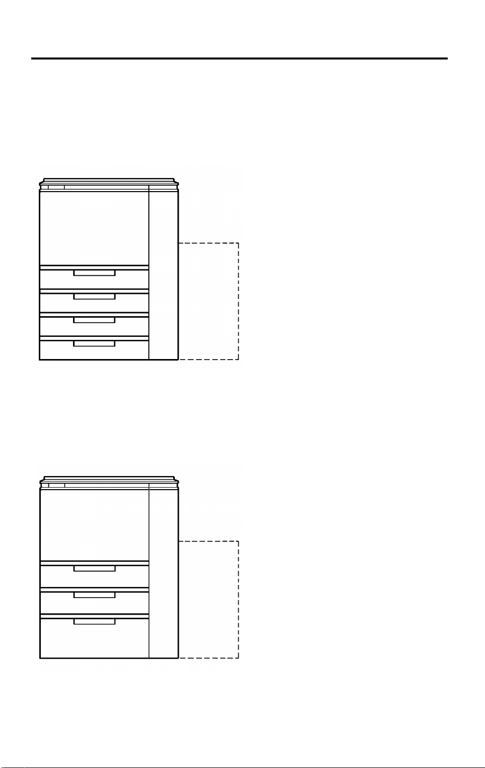
2.1 COPIER OVERVIEW
There are three types of mainframe.
A175 copier
Four 550-sheet paper trays
Optional 3,500-sheet large capacity
tray
550
550
(3,500)
550
550
A176V500.img
A176/A177 (U.S.A., Asia) copiers
Tandem paper tray
(including two 500-sheet paper tray)
One 550-sheet paper tray
1,500-sheet built-in large capacity
tray
Optional 3,500-sheet large capacity
tray
500 x 2 or 500
(3,500)
550
1,500
A176V501.img
1-6
Page 10

15 July 1996 MACHINE CONFIGURATION
A191/A192 (Europe) copiers
Tandem paper tray
Three 550-sheet paper trays
Optional 3,500-sheet large capacity
tray
500 x 2 or 550
(3,500)
550
550
550
A176V500.img
Overall
Information
1-7
Page 11
MACHINE CONFIGURATION 15 July 1996
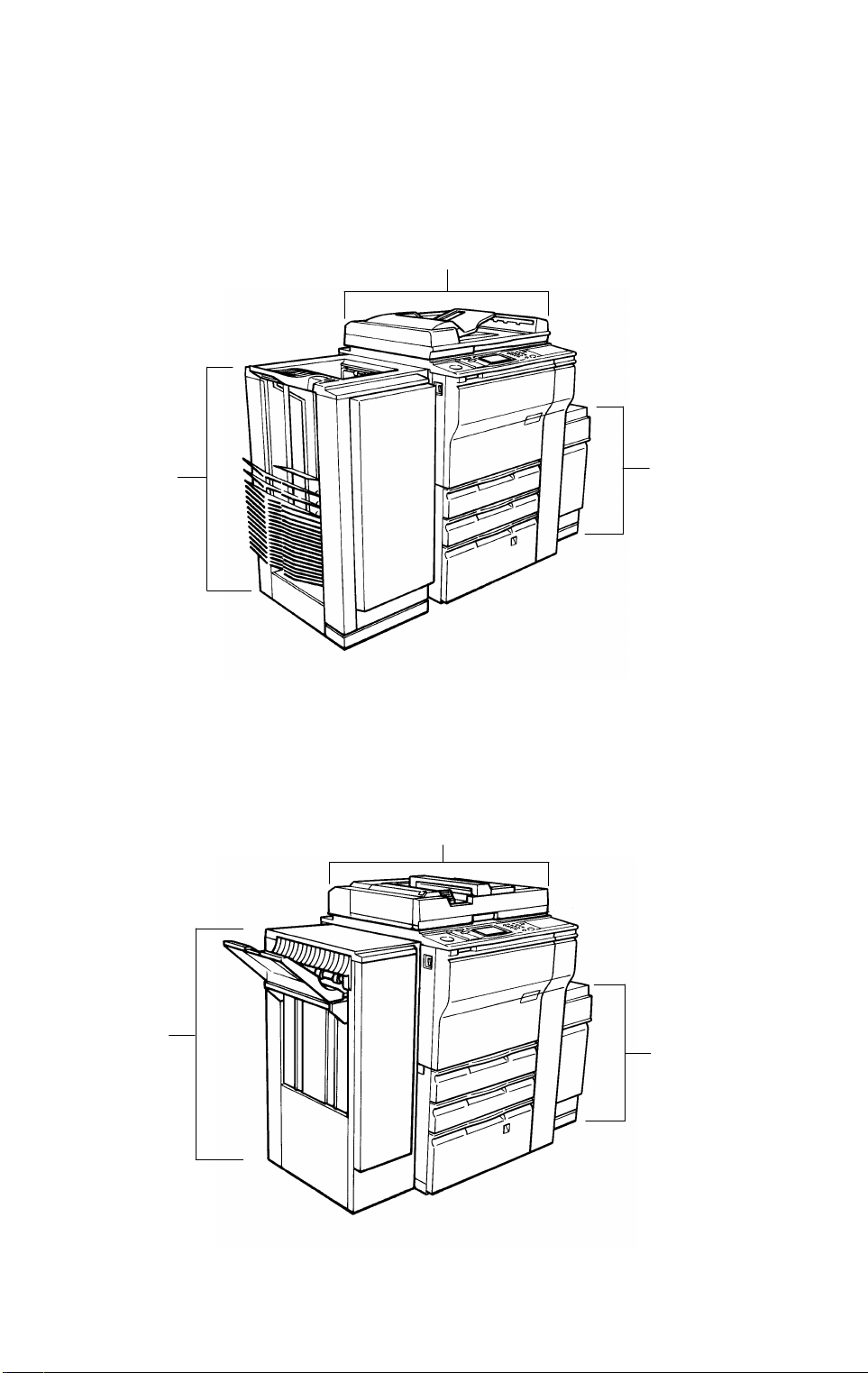
2.2 SYSTEM OVERVIEW
DJF version
(Mainframe type (A175/A176/A177 (U.S.A.), A175/A191/A192 (EU)) with dual
job feeder and floor type sorter stapler. The mainframe in the illustration
below is the A176.)
Dual job feeder (A610)
Floor type
sorter stapler
(A60617) or
3,500-sheets
large capacity
tray (A609)
Floor type
sorter stapler
with punch
(A60657, A60667)
A176V502.img
RDH version
(The mainframe (A175/A176/A177 (U.S.A.), A175/A191/A192 (EU)) with
recirculating document handler and finisher. The mainframe in the illustration
below is the A176.)
Recirculating document handler (A607)
Finisher
(A608)
3,500-sheets
large capacity
tray (A609)
A176V503.img
1-8
Page 12

15 July 1996 MACHINE CONFIGURATION
MEMO
Overall
Information
1-9
Page 13
COPY PROCESS AROUND THE DRUM 15 July 1996
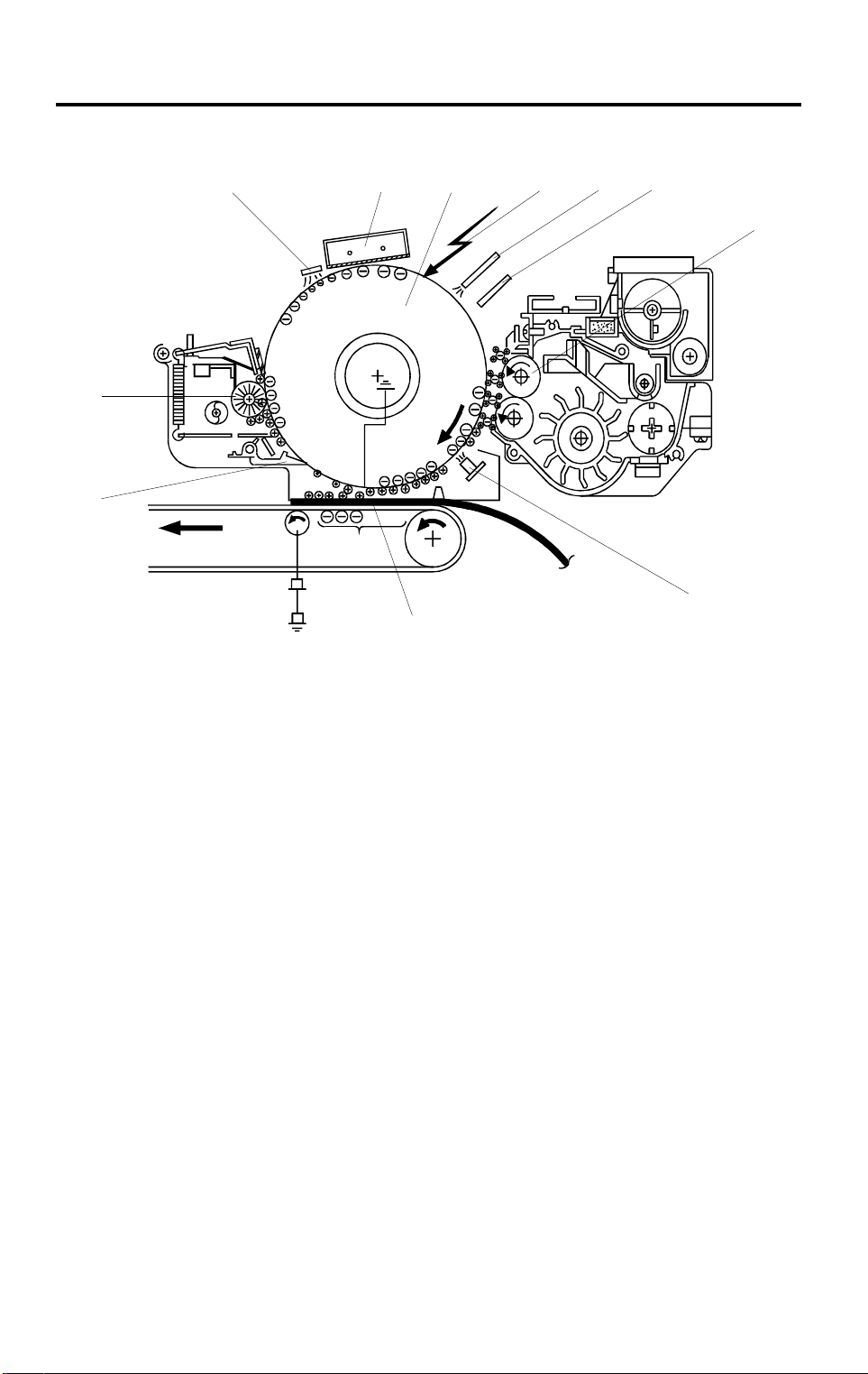
3. COPY PROCESS AROUND THE DRUM
11
12
5
43
10
9
7
8
A176V504.wmf
1. OPC DRUM
The organic photo conductive (OPC) drum (100 mm diameter) has high
resistance in the dark and low resistance under light.
6
2. DRUM CHARGE
In the dark, the charge corona unit gives a uniform negative charge to the
OPC drum. The charge remains on the surface of the drum. The amount of
negative charge on the drum is proportional to the negative grid bias voltage
applied to the grid plate on the charge corona unit.
3. EXPOSURE
An image of the original is reflected to the OPC drum surface via the optics
section. The charge on the drum surface is dissipated in direct proportion to
the intensity of the reflected light, thus producing an electrical latent image on
the drum surface.
The amount of charge remaining as a latent image on the drum depends on
the exposure lamp intensity controlled by the exposure lamp voltage.
4. ERASE
The erase lamp illuminates the areas of the charged drum surface that will
not be used for the copy image. The resistance of drum in the illuminated
areas drops and the charge on those areas dissipates.
1-10
Page 14

15 July 1996 COPY PROCESS AROUND THE DRUM
5. DRUM POTENTIAL SENSOR
The drum potential sensor detects the electric potential on the drum to
compensate image processing elements.
6. DEVELOPMENT
Positively charged toner is attracted to the negatively charged areas of the
drum, thus developing the latent image. (The positive triboelectric charge of
the toner is caused by friction between the carrier and toner particles.)
The development bias voltage applied to the development roller shaft
controls two things:
1) The threshold level if toner is attracted to the drum or toner remains on
the development roller.
2) The amount of toner to be attracted to the drum.
The higher the negative development bias voltage is, the less toner is
attracted to the drum surface.
7. PRE-TRANSFER LAMP (PTL)
The PTL illuminates the drum to remove almost all the negative charge from
the exposed areas of the drum. This makes image transfer easier.
8. IMAGE TRANSFER
Paper is fed to the drum surface at the proper timing so as to align the copy
paper and the developed image on the drum surface. Then, a negative
charge is applied to the reverse side of the copy paper by the transfer belt,
producing an electrical force which pulls the toner particles from the drum
surface onto the copy paper. At the same time, the copy paper is electrically
attracted to the transfer belt.
Overall
Information
9. PAPER SEPARATION
Paper separates from the OPC drum by the electrical attraction between the
paper and the transfer belt. The pick-off pawls help to separate the paper
from the drum.
10. CLEANING
The cleaning brush removes toner remaining on the drum after image
transfer and the cleaning blade scrapes off all the remaining toner.
11. QUENCHING
Light from the quenching lamp electrically neutralizes the charge potential of
the drum surface.
1-11
Page 15
MECHANICAL COMPONENT LAYOUT 15 July 1996
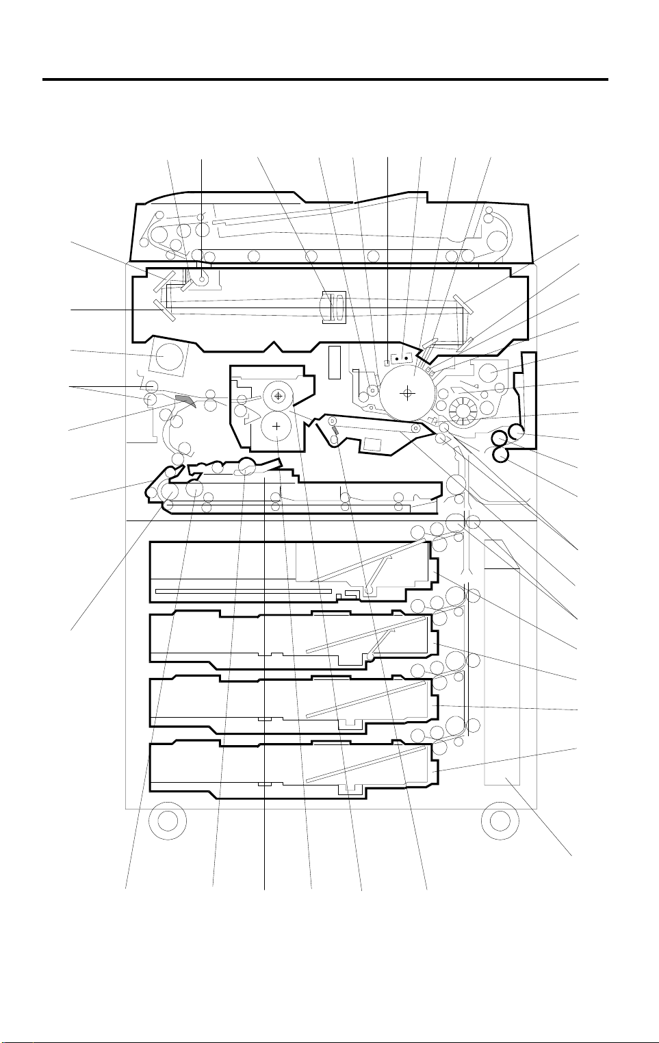
4. MECHANICAL COMPONENT LAYOUT
4
3
511
6
8
7
10
9
39
38
37
36
35
2
12
13
14
1
15
16
17
18
19
20
21
22
23
24
25
34
33
32
31
1-12
30
26
27
40
28
29
A176V505.wmf
Page 16

15 July 1996 MECHANICAL COMPONENT LAYOUT
Overall
Information
1. 3rd Mirror
2. 2nd Mirror
3. 1st Mirror
4. Exposure Lamp
5. Lens
6. Cleaning Brush
7. Cleaning Blade
8. Quenching Lamp
9. Charge Corona Unit
10. OPC Drum
11. 6th Mirror
12. 4th Mirror
13. 5th Mirror
22. Registration Rollers
23. Transfer Belt
24. Vertical Transport Rollers
25. Tandem Tray
550-sheet Tray
26. Universal Tray
27. 1500-sheet LCT
550-sheet Tray
28. Toner Collection Bottle
29. Transfer Belt Cleaning Blade
30. Hot Roller
31. Pressure Roller
32. Jogger Fences
33. Duplex Positioning Roller
14. Erase Unit
15. Drum Potential Sensor
16. Toner Hopper
17. Development Unit
18. Pre-Transfer Lamp
19. Pick-up Roller
20. Feed Roller
21. Separation Roller
34. Duplex Pick-up Roller
35. Duplex Feed Roller
36. Separation Belt
37. Junction Gate
38. Exit Rollers
39. Optics Cooling Fan
40. 550-sheet Tray
1-13
Page 17
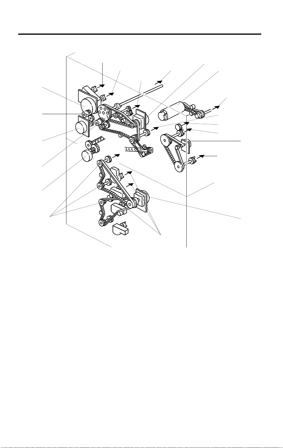
DRIVE LAYOUT 15 July 1996
5. DRIVE LAYOUT
9
10
11
1
❶
❷
❾
2
❽
❼
3
4
5
❸
6
❻
❺
8
❹
Main Motor
❶
Scanner Drive Motor
❷
Fusing/Duplex Drive Motor
❸
Paper Feed Motor
❹
Toner Collection Motor
❺
Registration Clutch
❻
By-Pass Feed Motor
❼
BY-Pass Feed Clutch
❽
Development Drive Motor
❾
7
A176V506.wmf
1. OPC Drum
2. Scanner Unit
3. Transfer Belt Unit
4. Paper Exit Unit
5. Fusing Unit
6. Duplex Unit
7. Paper Trays
8. Paper Feed Units
9. Toner Hopper
10. Development Unit
11. Cleaning Unit
1-14
Page 18
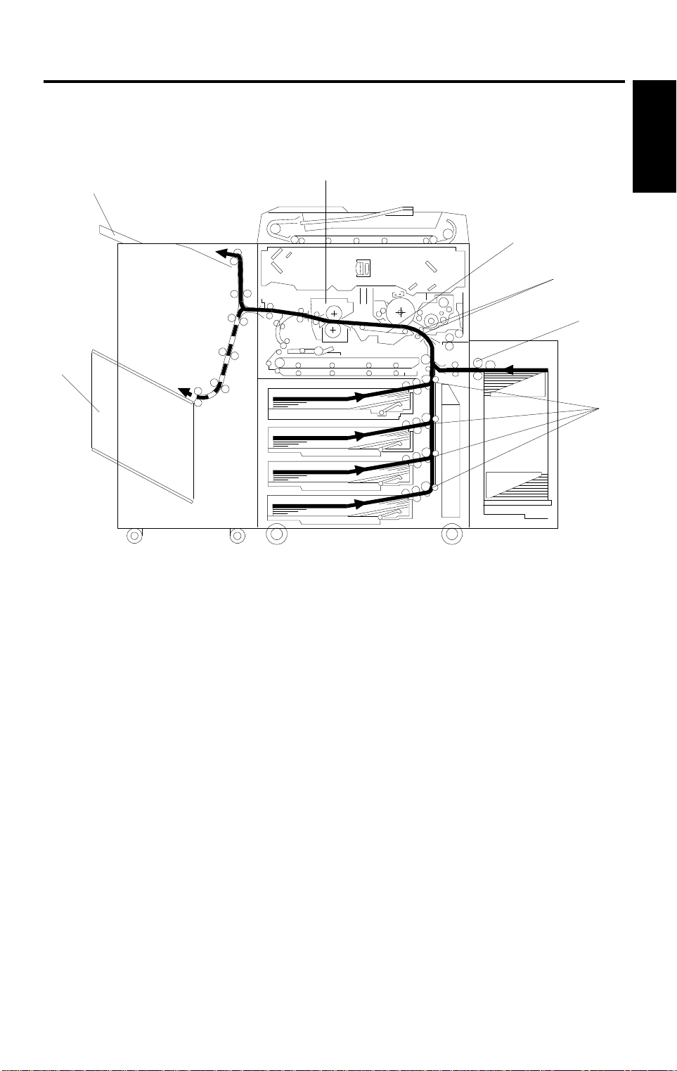
15 July 1996 PAPER PATH
6. PAPER PATH
6.1 STANDARD COPYING
[F]
[E]
[D]
[C]
[B]
[A]
[A]
Overall
Information
A176V507.wmf
Paper feed begins from the exterior LCT, by-pass feed table or paper feed
stations in the paper tray unit. The copy paper then follows one of two paths
inside the copier. The path followed depends on which mode the operator
has selected. For copy processing, all sheets follow the same paths from the
paper feed mechanism [A] through the registration rollers [B], transfer belt
[C], and fusing unit [D]. After that, copies are delivered to the sorter bins [E]
or proof tray [F], however, 2 sided copies are diverted for further processing.
1-15
Page 19
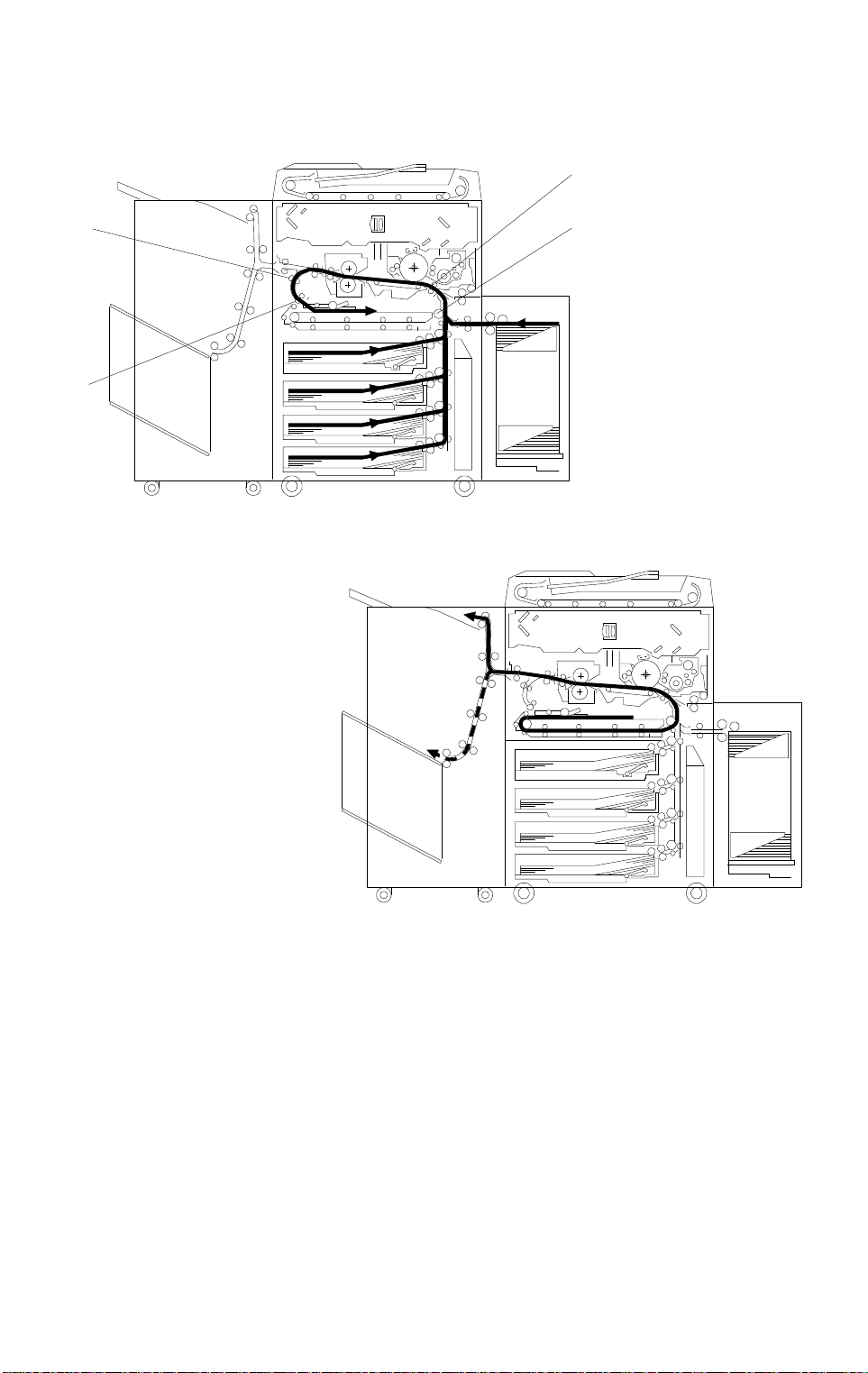
PAPER PATH 15 July 1996
6.2 MULTIPLE 2-SIDED CO PYI NG
a. Front Side
[D]
[A]
[B]
[C]
A176V508.wmf
b. Rear Side
A176V509.wmf
In this mode the junction gate [A] directs sheets exiting the fusing unit to the
duplex tray entrance. After that, all sheets follow the path through the duplex
entrance rollers [B].
After all front side copying is completed, the sheets on the duplex tray are fed
in order from the bottom to the top and follow the path through the duplex
feed mechanism and vertical transport rollers [C] to the registration rollers
[D]. After that, these sheets follow the same path as standard copying from
the registration rollers to the sorter.
1-16
Page 20

15 July 1996 ELECTRICAL COMPONENT DESCRIPTION
7. ELECTRICAL COMPONENT DESCRIPTION
Refer to the electrical component layout on the reverse side of the attached
Point to Point for symbols and index numbers.
Symbol Name Function Index No.
Motors
M1
M2
M3 Main Drives the main unit components. 44
M4 Develop ment Drive Drives the development unit. 45
M5 By-pass Fe ed Drives the by-pass feed rollers. 46
M6 3rd Scanne r Dr i ve Drives the 3rd scanner (dc steppe r) 47
M7
M8
M9
M10 Lens Horizontal Drive Shi f ts the lens horizontal position. 51
M11 Lens Vertical Drive Shifts the lens vertical position. 52
M12 Optic Cooling Fan Removes heat from the optics unit . 53
M13
M14
M15
M16
M17
M18
M19
M20
M21
Scanner Drive Drives the 1st and 2nd scanners (dc
servo).
Exhaust Fan Removes the heat fr om ar ound the
fusing unit.
Toner Bottle Drive Rotates the toner bottle to supply
toner to the toner hopper.
Charge Wire Cleaner
Drive
Jogger Drives the jogger fences to square the
Fusing/Dupl ex Drive Drives the fusin g uni t , the duplex unit,
Paper Feed Drives all feed and transpor t rol l ers in
1st Lift Raises the bottom plate in the 1st
2nd Lift Raises the bottom plate in the 2nd
Toner Collec tion Transports the col l ected toner to the
3rd Lift
(4 Tray version only)
Side Fence Drive
(Tandem vers i on only)
Rear Fence Drive
(Tandem vers i on only)
LCT Motor
(1,500 Tray ver si on only)
Drives the main charge wire cleaner to
clean the charg e w i re .
paper stack in the duplex tray (dc
stepper).
and the paper exi t r ol le r s.
the paper tray uni t.
paper tray.
paper tray.
toner collecti on bottle.
Raises the bottom plate in the 3rd
paper tray.
Opens and closes the front and the
rear side fences of th e ta ndem tray.
Moves the paper s st acked in the left
tandem tray to the right tandem tray.
Lifts and lowers the LCT bottom plate
to bring paper to t he f eed position and
allow loading of the paper.
42
43
48
49
50
54
90
91
92
93
94
95
96
127
Overall
Information
1-17
Page 21

ELECTRICAL COMPONENT DESCRIPTION 15 July 1996
Symbol Name Function Index No.
M22
M23
M24
M25
M26
AC Drive Cooling Fan
(60/70 CPM version only)
Optic Cooli ng Fan-2
(60/70 CPM version only)
Duplex Cool i ng Fan Cools the paper on the duplex tray to
Drum Cooling Fan
(70 CPM versio n onl y)
4th Lift
(4 Tray version only)
Remove heat from around the AC
drive unit.
Remove heat from the optic unit.
reduce the heat around the drum.
Cools the drum unit t o remove the
heat from the duplex tray.
Raises the bottom plate in the 4th
paper tray.
141
142
*143A, B
144
151
* (A: 60/70 CPM, B: 50/5 1 C P M )
Magnetic Clutches
MC1
Toner Supply Turns the toner supply ro l le r to supply
toner to the devel opment un it.
57
MC2 Registration Drives the r egi stration rollers. 58
MC3
By-pass Feed Starts paper feed from the by- pass
feed table.
60
Duplex Transport D rives the duplex transport rollers to
MC4
transport the pap er to the vertical
64
transport rollers.
MC5
MC6
MC7
MC8
MC9
Duplex Feed Starts paper feed from the dupl ex tray
to the du plex transport rollers.
1st Feed Starts paper feed from the 1st feed
tray.
2nd Feed Starts paper feed from the 2nd feed
tray.
3rd Feed Starts paper feed from the 3rd feed
tray.
4th Feed
(4 Tray version only)
Starts paper feed from the 4th feed
tray.
65
99
101
104
152
Switches
SW1
SW2
SW3
SW4
SW5
By-pass Table Det ect s i f the by-pass feed table is
open or closed.
Front Door Safety Cuts the ac power line and detect s i f
the front door is open or not.
1st Tray Set
Detects if the 1st tray is set or not.
(Non-Tandem version
only)
2nd Paper Size Determines what size paper i s i n th e
2nd (universal) paper tray.
Toner Overflow Detects w hen the toner collection
bottle is full.
1-18
25
29
66
67
75
Page 22

15 July 1996 ELECTRICAL COMPONENT DESCRIPTION
Symbol Name Function Index No.
SW6
SW7 Lo w er F ront Door Safety Detects if the front door is open or not. 83
SW8
SW9 Mai n Provides powe r to the copier 122
SW10
SW11
Solenoids
SOL1
SOL2
SOL3
SOL4
SOL5
SOL6
SOL7
SOL8
SOL9
SOL10
SOL11
SOL12
Toner Collection Bottle
Set
3rd Tray Set
(4 Tray version only)
Tray Down
(1500 Tray vers i on only)
4th Tray Set
(4 Tray version only)
Junction Gate Moves the junction gate to direct
Duplex Positioning Controls the up-down movem e nt of
By-pass Pick-u p Controls the up-down movem ent of
Guide Plate Opens the guide plate when a pap er
Transfer Belt Posi tio ni ng Controls the up-d ow n m ovement of
Pressure Arm Presses th e paper on the dupl ex t ray
Tandem Lock Locks the left tandem feed tray and
1st Pick-up Controls the up-down movem ent of
1st Separation Rol l er Controls the up-d ow n m ovement of
2nd Pick-up Controls the up-down movement of
2nd Separatio n R ol l er Controls the up-down movement of
3rd Pick-up Controls the up-down movement of
Detects if the toner collection bottle is
set or not.
Detects if the 3rd tray is set or not.
Lowers the LCT bot t om pl at e.
Detects if the 4th tray is set or not.
copies to the duplex tray or to the
paper exit.
the positioning roller.
the pick-up rol l er for by- pass feed.
misfeed occurs around th is area.
the transfer belt unit.
against the dupl ex feed rollers.
separates the ri ght and left tandem
trays.
the pick-up rol l er in the 1st feed
station.
the separation r ol l er i n the 1st feed
station.
the pick-up roller in the 2nd feed
station.
the separation r ol l er i n the 2nd feed
station.
the pic k-up roller in the 3r d f eed
station.
77
84
126
149
55
56
59
61
62
63
97
98
100
102
103
105
Overall
Information
1-19
Page 23

ELECTRICAL COMPONENT DESCRIPTION 15 July 1996
Symbol Name Function Index No.
3rd Separation Ro ll er Controls the up-down movement of
SOL13
the separation r ol l er i n the 3rd feed
106
station.
SOL14
4th Pick-up
(4 Tray version only)
Controls the up-down movement of
the pic k-up roller in the 4t h f eed
153
station.
SOL15
4th Separation Rol l er
(4 Tray version only)
Controls the up-down movement of
the separation r ol l er i n the 4th feed
154
station.
Sensors
S1
Scanner HP Informs the CPU when the 1st and
2nd scanners are at th e home position .
1
Platen Cover Position-1 Informs the CPU that the platen cover
S2
is in the up or down po sition (related
2
to APS/ARE function).
Platen Cover Position-2 Informs the CPU that the platen cover
S3
is in the up or down po sition to detect
3
if the original has been removed or not.
S4
S5
S6
S7
S8
S9
Lens Vertical HP Informs the CPU that the lens is at the
full-size posi t i on.
Lens Horizont al H P Informs the CPU t hat th e l ens is at the
horizontal home position.
3rd Scanner HP Informs the CPU when the 3rd
scanner is at the hom e position.
By-Pass Paper End Informs the CPU that there is no
paper in the by-pass feed table.
Guide Plate Position Informs the CPU if the registration
guide plate is closed or not.
Jogger HP Detects if the duplex jogger fen ces
are at the home po si t i on or not .
4
5
6
7
8
9
Vertical Transport Detects the leading edge of the paper
S10
to determine the paper feed timi ng of
10
the next sheet.
Duplex Exit Detects the leadi ng edge of the paper
S11
to determine the duplex transpor t
11
clutch on timing.
Duplex Entranc e Sensor Detects the leadi ng edge of the paper
S12
to determine the duplex feed clut ch off
12
timing.
S13 Duplex Paper End Detects paper in the dup l ex t ra y. 13
Duplex Transport D et ect s t he l eading edge of t he paper
S14
to control the jogger motor and the
14
positioning sol enoid on timing.
S15 Exit Detects misfee ds. 15
1-20
Page 24

15 July 1996 ELECTRICAL COMPONENT DESCRIPTION
Symbol Name Function Index No.
S16 Fusing Exit Detects misfeeds. 16
S17 Paper Guide Detects misfeeds. 17
S18
S19 Original Length-1 Detects original length. 21
S20 Original Length-2 Detects original length. 22
S21 Original Width Detect s or i gi nal width. 23
S22
S23
S24
S25 Toner Near End Detects toner end condi t i on. 30
S26
S27 Drum Potential Detects the drum surface potentia l . 39
S28
S29
S30
S31
S32
S33
S34
S35
S36
S37
S38
S39
Auto Image Density Senses the background density of the
original.
By-Pass Paper Size Informs the CPU what size paper is in
the by-pass feed table.
Toner Density Senses t he amount of toner in the
black develop er .
Registratio n Detects misfeeds and control s
registration clutch off-on tim ing.
Auto-Response Returns the displ ay from the scree n
saver.
Image Density Detects the density of th e ID sensor
pattern on the drum.
1st Pape r End Informs the CPU when the 1st
cassette runs ou t of paper.
1st Pape r Near End I nforms the CPU when t he 1st
cassette is in nea r end condition.
1st Paper Feed Controls t he 1st paper feed clu tc h
off/on timing and the 1st pick-up
solenoid off ti m i ng.
2nd Paper Near End Informs the CPU when the 2nd
cassette is in nea r end condition.
1st Lift Detects the correct feed height of th e
1st cassette.
2nd Paper End Informs the CPU when the 2nd
cassette runs ou t of paper.
Toner Collec tion Motor Detects the toner col l ect i on motor
operation.
2nd Lift Detects the correct feed height of th e
2nd cassette.
3rd Lift Detects the correct feed height of the
3rd cassette.
3rd Paper Near End
(4 Tray version only)
3rd Paper End Informs the CPU when the 3rd
Informs the CPU when the 3rd
cassette is in nea r end condition.
cassette runs ou t of paper.
20
26
27
28
34
41
68
69
70
71
72
73
74
76
78
79
80
Overall
Information
1-21
Page 25

ELECTRICAL COMPONENT DESCRIPTION 15 July 1996
Symbol Name Function Index No.
3rd Paper Feed Controls the 3rd paper feed clutch
S40
off/on timing and the 3rd pick-up
81
solenoid off ti m i ng.
2nd Paper Feed Controls the 2nd paper feed clut ch
S41
off/on timing and the 2nd pick-up
82
solenoid off ti m i ng.
S42
Base Plate Down
(Tandem vers i on only)
Detects when the bottom plate is
completely lowered to stop the 1st lift
85
motor.
S43
S44
S45
S46
S47
S48
S49
S50
S51
S52
S53
S54
Side Fence Positioning
(Tandem vers i on only)
Rear Fence Retur n
(Tandem vers i on only)
Rear Fence HP
(Tandem vers i on only)
Left Tandem Paper En d
(Tandem vers i on only)
LCT Near End
(1,500 Tray ver si on only)
Tray Down
(1,500 Tray ver si on only)
Tray Paper Set
(1,500 Tray ver si on only)
Side Fence Close
(Tandem vers i on only)
4th Lift
(4 Tray version only)
4th Paper Near End
(4 Tray version only)
4th Paper End
(4 Tray version only)
4th Paper Feed
(4 Tray version only)
Informs the CPU when the tandem
tray side fences are open.
Informs the CPU when the tandem
tray rear fence is i n th e return position.
Informs the CPU when the tandem
tray rear fence is i n th e home position .
Informs the CPU when the left tandem
tray runs out of paper.
Detects the paper near end conditi on.
Detects when the tray is completely
lowered to stop the LCT motor.
Informs the CPU when the paper is
set on the LCT botto m tr ay.
Detects whether the side fence close
or not.
Detects the correct feed height of th e
4th cassette.
Informs the CPU when the 4th
cassette is in nea r end condition.
Informs the CPU when the 4th
cassette runs ou t of paper.
Controls the 4th pa per feed clutch
off/on timing and the 4th pick-up
86
87
88
89
123
124
125
150
145
146
147
148
solenoid off ti m i ng.
PCBs
PCB1
AC Drive Provides AC power to the exposure
lamp and fusing lamp.
PCB2 Main Controls all machine functions. 109
PCB3 Optic Con trol Controls all op tics components. 110
PCB4
PCB5
Development Bi as
Control
Paper Feed Cont rol Controls all components i n t he paper
Controls the outp ut of development
bias.
bank.
1-22
108
111
112
Page 26

15 July 1996 ELECTRICAL COMPONENT DESCRIPTION
Symbol Name Function Index No.
PCB6 DC Power Supply Unit Provides DC power. 113
PCB7 Guidance Controls the guidance display. 120
PCB8
Lamps
L1
L2 Fusing Provides heat to the hot roller. 32
L3
L4
L5
Operation Panel Controls the LED matrix, and monitors
the key matrix.
Exposure Applies high intensity light to the
original for exposure.
Quenching Neutralizes any charge remaining on
the drum surface a fter cl eaning.
Erase Discha r ges the drum outside the
image area.
Pre-transfer Reduces the charge on the drum
surface before tr ansfer.
121
18
37
38
40
Overall
Information
Power Packs
Transfer Provides high voltage for the transfer
PP1
Charge Provides high vo ltage fo r t he charge
PP2
Others
TS1
TF1
TH1
TH2
TH3
H1
H2
RA1 Main Power Relay Controls main power. 107
Optics Therm oswitch Opens the exposure lam p ci r cui t i f the
Fusing Therm of u se Opens the fusing lamp circuit i f the
Fusing Therm i st or Senses the tempera ture of the hot
Optics Therm i st or Monitors the temperature of the optics
Drum Thermistor
(Located on the ID
Sensor Ass’y)
Transfer
Anti-Condensation
Optics Anti-Condensation Turns on when the main switch is off
belt and controls t he t ransfer belt
positioning solenoid.
corona wires, and t he grid plate.
Controls QL, PTL, and charge wire
cleaner motor functions.
optics unit overheats.
fusing unit overheats.
roller.
cavity.
Monitors the temperature of the OPC
drum. 41
Turns on when the main switch is off
to prevent moisture from forming on
the transfer belt.
to prevent moisture from forming on
the optics.
117
119
19
33
24
36
31
35
1-23
Page 27

ELECTRICAL COMPONENT DESCRIPTION 15 July 1996
Symbol Name Function Index No.
CO1
NF1 Noise Filter Removes ele ct rical noise. 115
CB1
LA1
Total Counter Keeps track of the total number of
copies made.
Circuit Breake r Provides back-up high current
protection for the electrical
components.
Lightening Arrestor Removes current surges from the AC
input lines.
114
116
118
1-24
Page 28

SECTION 2
DETAILED SECTION
DESCRIPTIONS
Page 29
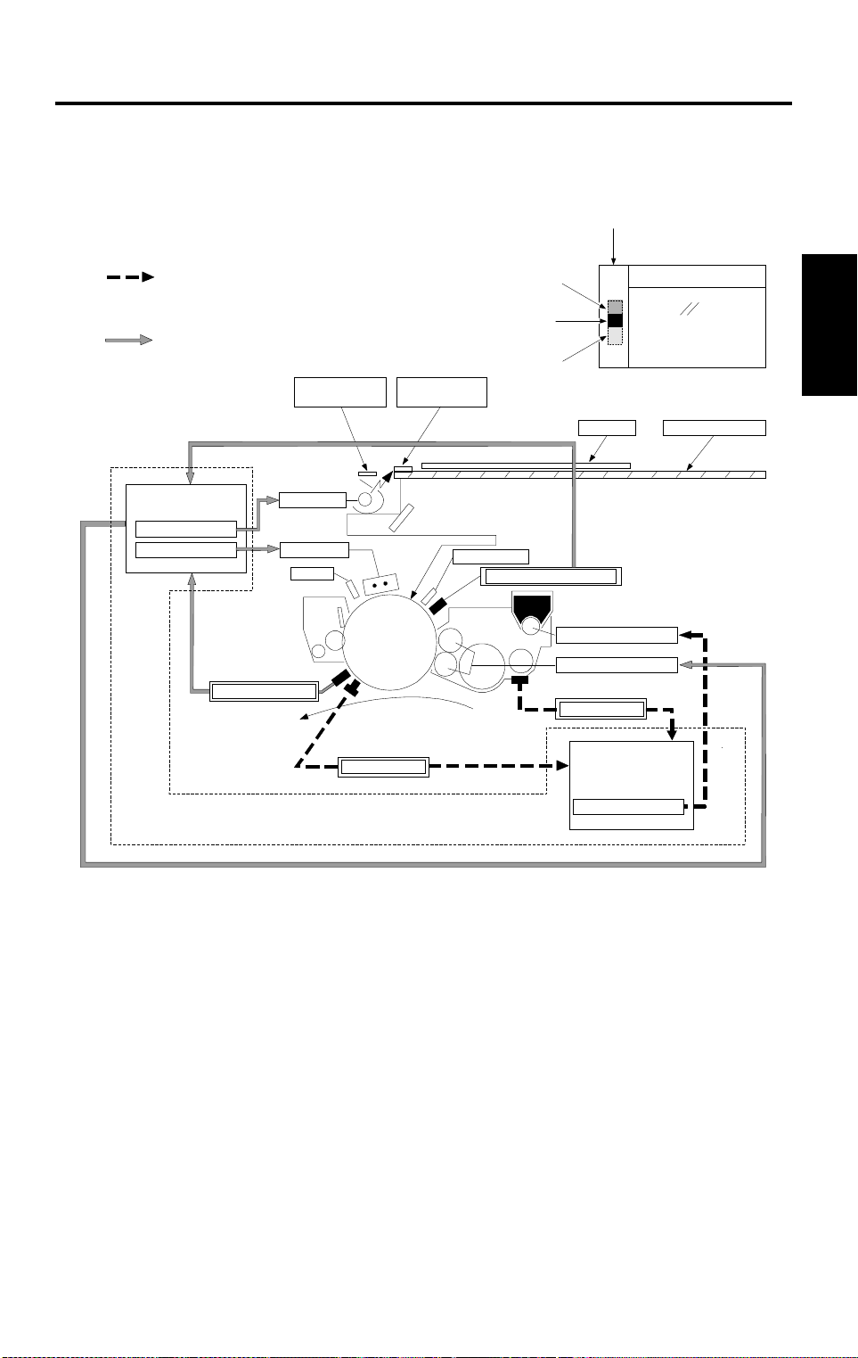
15 July 1996 PROCESS CONTROL
1. PROCESS CONTROL
1.1 OVERVIEW
Image Density Control
ADS Pattern
Original Scale
(Fuzzy Control)
V
Pattern
D
Latent Image Control
Detailed
Descriptions
Latent image Control
Exposure Control
Charge Control
Drum Thermistor
Lamp Voltage
Grid Voltage
QL
Paper
V
D
Pattern
Pattern
V
L
VL Pattern
Original Exposure Glass
Erase Lamp
Drum Potential Sensor
Toner Supply On time
Development. Bias
TD Sensor
ID Sensor
Image Density Control
(Fuzzy Control)
Toner Supply Control
Main PCB
A176D500.wmf
This model uses two process control methods. One compensates for
variation in the drum potential (latent image control) and the other controls
the toner concentration and toner supply amount (image density control).
2-1
Page 30

PROCESS CONTROL 15 July 1996
1.1.1 Latent Image Control
L
Q
Charge
Vo
Exposure
Black
V
D
White
Erase
V
L
V
A176D501.wmf
Potential
Sensor
R
Drum
The figure shows the changes of the drum potential during the copy process.
O
V
: The drum potential just after charging the drum.
D
(Dark Potential): The drum potential just after exposing the black
V
pattern (V
L
(Light Potential): The drum potential just after exposing the white
V
pattern (V
R
(Residual Voltage): The drum potential just after the exposure of the
V
D
pattern)
L
pattern)
erase lamp.
After long usage following installation or a PM, drum potential will gradually
increase due to the following factors:
Dirty optics or exposure lamp deterioration
Dirty charge corona casing and grid plate
Change of the drum sensitivity
In this copier, the change in drum potential is detected by the drum potential
sensor and the following items are controlled to maintain good copy quality.
The grid bias voltage
The exposure lamp voltage
The development bias voltage.
A drum thermistor detects the drum temperature and this data is also used to
control the above voltages. It is impossible to explain simply because it is
controlled by methods developed in our laboratories using an artificial neural
network.
2-2
Page 31

15 July 1996 PROCESS CONTROL
1.1.2 Image Density Control
Image density is controlled by the following sensors:
Toner density sensor (TD sensor)
Image density sensor (ID sensor)
Data from the TD sensor is used to keep the toner concentration in the
developer at a constant level. However, the image on the OPC drum varies
due to the variation of toner chargeability (influenced by the environment)
even if the toner concentration is constant. By the ID sensor compensation,
toner concentration is changed to keep the image density on the OPC drum
constant.
The following items are controlled to maintain a constant copy image density:
Toner supply clutch on time
Detailed
Descriptions
Toner supply level data (V
REF
) of the TD sensor
2-3
Page 32

PROCESS CONTROL 15 July 1996
1.2 PROCESS CONTROL DATA INITIAL SETTING
The following flow chart shows all the steps that will be performed whenever
the machine is turned on while the hot roller temperature is below 100°C.
This initializes all the process control settings.
Main SW On (Fusing Temp. < 100°C)
Charge wire cleaning (if more than 5 k copies are made since last
cleaning)
Drum Potential Sensor Calibration
①
Drum Conditioning Start (Fusing Temp. = 180°C)
VSG Adjustment
Transfer belt voltage detection
VR Measurement
VD/VL Correction
TD Sensor Detection
②
ID Sensor Detection/Correction
③
ADS Adjustment
① : See Latent Image Control section
(Page 2-5) for details.
② : See Image Density Control section
(Page 2-12) for details.
③ : See Optics section (Page 2-39) for details.
2-4
Page 33

15 July 1996 PROCESS CONTROL
1.3 LATENT IMAGE CONTROL
1.3.1 Drum Potential Sensor Calibration
Case
Sensor
[A]
Drum
A176D503.wmf
Output
Amp.
Detailed
Descriptions
[B]
Main PCB
A176D502.wmf
The drum potential sensor [A] is located just above the development unit. The
sensor has a detector which detects the strength of the electric field from the
electric potential on the drum. The output of the sensor depends on the
strength of the electric field.
Since the output of the sensor is affected by environmental conditions, such
as temperature and humidity, the sensor output is calibrated during process
control data initial setting.
The High Voltage Control PCB [B] has two relay contacts. Usually RA602
grounds the drum. However, during the initial setting, the main PCB turns
RA601 on and RA602 off and applies the voltage to the drum shaft.
By measuring the output of the drum potential sensor when –100 V and –800
V are applied to the drum, the sensor output is calibrated automatically.
(The machine recognizes the relationship between actual drum potential and
the potential sensor output.)
2-5
Page 34

PROCESS CONTROL 15 July 1996
1.3.2 Drum Conditioning
When the fusing temperature reaches 180°C, the machine starts the drum
conditioning process. In this mode, the main motor, main charge corona,
erase lamp and development bias are activated for about 30 seconds and
R
drum sensitivity and residual voltage (V
) are stabilized, as in continuous
copy runs.
SG
1.3.3 V
Adjustment
During drum conditioning, the ID sensor checks the bare drum’s reflectivity
and calibrates the output of the ID sensor to 4 ± 0.2 V.
R
1.3.4 V
Measurement
O
V
[–V]
V
D
New Drum
Used Drum
Drum
Potential
Dark
L
V
R
V
LightOriginal Density
A176D504.wmf
The above figure shows the relationship between the drum potential and the
original density. To get constant copy quality, this relationship must be
maintained.
Since this relationship tends to change to the one represented by the dotted
line by various factors, compensations are required.
R
The residual voltage (V
voltage is increased. Therefore, the V
) cannot be compensated even if the exposure lamp
R
change has to be compensated by
other means.
The main control board checks the drum potential just after the erase lamp
exposure by the drum potential sensor after drum conditioning. This
measured drum potential is in fact V
D
V
and VL corrections.
R
. This VR is used as the standard for the
NOTE:
In the figure above, the residual voltage (V
R
) for the new drum is 0 V.
Actually, there is some residual voltage even on the new drum.
2-6
Page 35

15 July 1996 PROCESS CONTROL
1.3.5 VD Correction
Exposure
[–V]
Drum
Potential
–770
Dark
D
V
New Drum
V
VD Pattern
Glass
A176D505.wmf
R
D
Compensated
V
Detailed
Descriptions
After many copies
R
V
LightOriginal Density
A176D506.wmf
D
The drum potential just after the black pattern (V
Pattern) is exposed (VD:
Dark Potential) tends to lower during drum life due to a decrease in the
drum’s capacity to carry a charge.
D
To check the actual V
D
V
pattern (Black) stuck on the bottom side of the exposure glass bracket is
, the first scanner moves to the home position and the
exposed on the drum.
D
The main control board measures V
adjusts it to a target value by adjusting the grid bias voltage (V
On the other hand, there is a change of the drum residual voltage (V
that the target V
D
Target V
Value: VD = VR + (–770)
D
voltage is compensated as follows:
The adjusted grid bias voltage (V
through the drum potential sensor and
GRID
GRID
) is kept in memory until the next
).
R
process control data initial setting.
), so
2-7
Page 36

PROCESS CONTROL 15 July 1996
1.3.6 VL Correction
Exposure
Glass
[–V]
VL Pattern
D
V
D
and V
L
Compensated
A176D505-2.wmf
Drum
V
D
Only V
Compensated
R
V
L
V
Potential
New Drum
R
–770
V
–140
R
V
Dark LightOriginal Density
A176D507.wmf
Dirty optics and/or exposure lamp deterioration decreases the intensity of the
light that reaches the drum. In addition to this, the drum sensitivity also
changes during the drum’s life. These factors change the drum potential just
L
after white pattern exposure (V
L
To check the actual V
L
V
pattern (White) stuck underneath the original scale is exposed on the
, the lens moves to the VL pattern check position. The
: Light Potential).
drum.
L
The main control board measures V
adjusts it to a target value by adjusting the exposure lamp voltage (V
The residual voltage (V
R
) change also affects VL, so that VL’s target voltage
through the drum potential sensor and
LAMP
).
is compensated as follows:
L
Target V
Value: VL = VR + (–140)
The adjusted exposure lamp voltage (V
next process control data initial setting.
2-8
LAMP
) is stored in memory until the
Page 37

15 July 1996 PROCESS CONTROL
1.3.7 VR Correction
[–V]
D
V
R
V
V
L
Development Bias (V
BB
)
Drum
Potential
–770
V
R
D
V
and VL Compensated
New Drum
–140
R
V
Potentials (V
Dark
R
, VD, VL) are monitored by the potential sensor. (This is done
Original Density
Light
A176D508.wmf
only when the fusing temperature is less than 100°C after the machine is
turned on.)
During the check cycle, the V
D
and VL patterns are exposed and the drum
potential on the area where exposed by each pattern is checked by the
potential sensor.
D
Compare the curve of the V
and VL compensated drum potential with the
curve of the new drum, they are parallel but the compensated potential is still
higher (V
increased residual potential, development bias (V
R
) than the new drum potential. To prevent dirty backgrounds due to
BB
) is applied as follows:
Detailed
Descriptions
BB
= VR + (–220)
V
2-9
Page 38

PROCESS CONTROL 15 July 1996
1.3.8 Initial Setting Sequence
The following graph shows the sequence of events during process control
data initial setting.
for the purpose
of ADS sensor
correction
Exposure
Lamp
Potential
D
800
V
100
V
V
L
V
R
V
New V
New V
R
D
New V
L
Sensor
Output
1. Potential
sensor
2. V
R’
, VD’, VL’
potential
3. VD, V
correction
L
4. ID sensor
pattern
potential
Latent Image Control
A176D509.wmf
1. Potential sensor calibration
By measuring the output of the drum potential sensor when –100 V and
100
–800 V are applied to the drum, the sensor output (V
and V
calibrated automatically (See page 2-5 for details).
800
) is
R
2. V
, VD, VL potential detection
After about 30 seconds of drum conditioning, V
developed by using the previous grid bias voltage (V
exposure lamp voltage (V
The machine calculates the new V
detected V
R
, VD, VL data.
LAMP
) data to detect the VR, VD, VL data.
GRID
and V
2-10
D
and VL Patterns are
GRID
) data and
LAMP
data using the
Page 39

15 July 1996 PROCESS CONTROL
3. VD and VL corrections
Using the calculated V
GRID
and V
developed again and the new V
LAMP
data, VR, VD, and VL patterns are
R
, VD, and VL data are detected.
If both V
D
and VL data are within specifications, the new V
GRID
, V
and development bias (VBB) are determined based on the new VD, VL,
and V
R
values.
Specifications:
D
V
= –770 + VR ± 20 V
L
V
= –140 + VR ± 20 V
D
is outside specifications, V
If V
is measured again and V
The same is done for V
D
L
and V
The above process continues until both V
The graph on the previous page shows the example when only V
outside specifications at the first V
specifications after one V
L
GRID
is shifted one step. Then the VD pattern
is detected again.
LAMP
.
D
and VL fall within specifications.
L
detection and it became within
correction (V
LAMP
L
was
is changed 0.5V/step , V
changed 20V/step).
100
If V
D
if V
or VL do not fall within specifications after V
the maximum or minimum level, the machine stops V
uses the previous V
or V
800
at drum potential sensor calibration is outside specifications or
GRID
and V
LAMP
values during copying.
GRID
LAMP
or V
D
or VL correction and
are shifted to
In this case, nothing is indicated on the machine but the SC counter is
incremented.
LAMP
GRID
Detailed
Descriptions
is
Related SC codes (see troubleshooting section for details):
Code Condition
361 Incomplete drum potential sensor calibrati on
D
364 Abnormal V
365 Abnormal V
366 V
R
abnormal
detection
L
detection
Development bias is also decided by using VR as follows.
BB
= VR + (–220)
V
4. ID sensor pattern potential detection
This is performed to determine ID Sensor Bias Voltage. The details are
explained in the development control section (see page 2-16).
2-11
Page 40

PROCESS CONTROL 15 July 1996
1.4 IMAGE DENSITY CONTROL
1.4.1 Toner Density Sensor
A: V
B: V
C: V
OUT
(Gain dat a) is high .
OUT
is within the specification.
OUT
(Gain dat a) is
low.
V
A176D531.wmf
V
OUT
IN
= VIN x
= 12 x
Main PCB
V
AGC
Gain
256
Gain
256
OUT
D
(12 V)
V
GND
Sensor
Output
TD
Sensor
A176D510.wmf
Developer consists of carrier particles (iron) and toner particles (resin and
carbon). Inside the development unit, developer passes through a magnetic
field created by coils inside the toner density sensor. When the toner
concentration changes, the voltage output by the sensor changes accordingly.
<Toner Density Sensor Initial Setting>
When new developer with the standard toner concentration (2.0% by weight,
20 g of toner in 1000 g of developer) is installed, developer initial setting must
be performed by using SP mode ( SP Adjustment - PAGE 1).
During this setting, the output voltage (V
OUT
) from the auto gain control
circuit (AGC) on the main control board PCB varies to change the output
voltage from the toner density (TD) sensor. This is done by changing the gain
data, see below.
V
OUT
= VIN x
Gain Data
If the data is high, V
256
OUT
= 12 x
becomes high, and the sensor output voltage
Gain Data
256
becomes high. As a result, the sensor characteristic becomes as illustrated
by curve A. If the data is low, V
OUT
becomes low, and the sensor output
voltage becomes low. As a result, the sensor characteristic shifts as
illustrated by curve C.
2-12
Page 41

15 July 1996 PROCESS CONTROL
By selecting the proper gain data, the sensor output is set within the targeted
control le vel (V
REF
, V
REF
= 2.5 ± 0.1 V). Now, the sensor characteristic is
illustrated by curve B and the TD sensor initial setting is completed.
The selected gain data is stored in memory, and V
OUT
from the auto gain
control circuit stays constant during the toner sensor detection cycle.
<Toner Supply Criteria>
At every copy cycle, toner density in the developer is detected once. The
sensor output voltage (V
toner supply level voltage (V
TD
) during the detection cycle is compared with the
REF
).
Detailed
Descriptions
2-13
A176D511.wmf
Page 42

PROCESS CONTROL 15 July 1996
<Toner Supply Clutch on Time>
To stabilize toner concentration, toner supply amount (toner supply clutch on
time) is controlled by referring to V
REF
and VTD.
The toner supply amount is calculated at every copy. The toner supply
amount is determined by using the following factors.
①
②
V
V
REF
REF
TD
– V
– VTD’(VTD’ = VTD of the previous copy cycle)
A176D512.wmf
By referring to these factors, the machine recognizes the difference between
the current toner concentration and the target toner concentration. The
machine also understands how much toner concentration has changed and
predicts how much the toner supply amount will probably change.
By changing the toner supply amount precisely, toner concentration (image
density) is kept at a constant level.
Since the toner supply clutch on time updating is under fuzzy control, the
relation among V
TD
, VTD’, V
REF
cannot be expressed by a simple algebraic
formula.
REF
<V
Correction>
The image on the OPC drum changes due to variation of toner chargeability
(influenced by the environment) even if the toner concentration is constant.
The image density sensor (ID sensor) directly checks the image on the OPC
drum and shifts V
REF
data (under fuzzy control) to keep the image on the
OPC drum constant, as explained in the next section.
NOTE:
1) Toner end condition is detected by the toner end sensor (see the
development section for details).
2) The toner supply clutch turns on at the intervals between each
copy process while image development is not performed.
2-14
Page 43

15 July 1996 PROCESS CONTROL
1.4.2 Image Density Sensor Detection
[B]
[C]
Drum
[A]
bias
A176D513.wmf
SG
and VSP are checked by the ID sensor [A]. The ID sensor is located
V
A176D514.wmf
underneath the drum cleaning section.
There is no ID sensor pattern in the optics, however, a pattern image is made
on the OPC drum by the charge corona unit [B] and the erase lamp [C].
SG
V
is the ID sensor output when checking the erased drum surface.
SP
V
is the ID sensor output when checking the ID sensor pattern image.
Detailed
Descriptions
To compensate for any variation in light intensity from the sensor LED, the
reflectivity of both the erased drum surface and the pattern on the drum are
checked.
VSP Detection
1st Series of
SG
V
Detection
SG
V
is detected every time the machine starts copying.
During V
SG
Copies (8 copies)
SG
V
Detection
detection, the development sleeve rollers do not rotate and no
V
2nd Series
of Copies
(5 copies)
SP
Detection
SG
V
Detection
3rd Series
of Copies
(17 copies)
SP
V
Detection
A176D515.wmf
SG
V
Detection
development bias is applied.
SP
V
is detected after copying is completed if 10 or more copies have been
made since V
when checking V
SP
was last detected. Since the transfer belt must be released
SP
, a VSP check cannot be done during continuous copying.
2-15
Page 44

PROCESS CONTROL 15 July 1996
①
Potential
V
P
–700 V
①
Sensor Detection
P
②
ID Sensor
Bias Level
V
③
–300
IDB
V
= VP +300 (V)
②
4.0 V
SP
③
ID Sensor
Output
V
A176D517.wmf
A176D516.wmf
While developing the ID sensor pattern, ID sensor bias is applied. ID sensor
bias is determined during process control data initial setting as follows:
Apply charge while grid voltage is –700 V to create the ID sensor pattern.
Check the drum potential (V
P
) of the latent image created by the charge with
–700 V grid.
IDB
Adjust the ID sensor bias (V
IDB
= VP – (–300) (V)
V
P
+ 300 (V)
= V
Change the bias to the calculated V
SG
adjustment sequence in the process control data initial setting and V
V
are used to determine V
IDB
V
is not changed until the next process control data initial setting is done.
REF
<V
correction timing>
REF
) so that it satisfies the following formula.
IDB
and detect VSP. VSG detected during
data at process control data initial setting.
After the series of copies is completed in the case that 10 or more copies
have been made, V
SG
V
, VSP and the current TD sensor output (VTD).
Since this V
REF
V
, V
REF
REF
’, VSG, VSP and VTD cannot be expressed by a simple algebraic
REF
is updated by referring to the previous V
data updating is under fuzzy control, the relationship among
REF
(V
REF
formula.
SP
’),
REF
is updated not only at the above case. But also during developer initial
V
setting and during process control data initial setting.
2-16
Page 45

15 July 1996 PROCESS CONTROL
1.4.3 Sensor Abnormal Conditions
a. ID sensor (V
Whenever V
REF
V
data and toner concentration is controlled only by using TD sensor
SG,VSP
SG
falls under 2.5 V or VSP rises over 2.5 V, the CPU fixes the
) abnormal
output.
SG
V
and VSP are still detected as usual during abnormal conditions and if
SG
output returns to normal levels (V
≥ 2.5 V, VSP ≤ 2.5 V), the CPU returns
the toner concentration control to normal mode.
b. TD sensor (V
Whenever V
TD
) abnormal
TD
rises over 4.0 V or VTD falls under 0.5 V, the CPU shifts the
toner supply to the fixed supply mode. In this condition, the CPU never stops
the toner supply. The fixed toner supply amount can be changed in four steps
(4%, 7%, 11%, 14%) by using SP mode. The default fixed toner supply
amount is 4%.
TD
is still detected as usual during the abnormal condition and if its output
V
returns to a normal level, the CPU returns the toner concentration control to
normal mode.
c. Drum Potential Sensor abnormal
Detailed
Descriptions
Whenever V
rises over 4.2 V or V
100
rises over 0.7 V or V
800
falls under 2.7 V, the CPU also shifts the toner
supply to the fixed supply mode, as for a TD sensor (V
100
falls under 0.1 V or whenever V
TD
) abnormal condition.
Related SC codes. (See troubleshooting section of details.):
Code Condition
351 Abnormal V
352 Incomplete TD Sensor Initial Set t i ng
353 Abnormal VSP Detection (VSP > 2.5 V)
354
355 Abnormal V
356 Abnormal V
357 Abnormal V
358 Abnormal V
361 Incomplete Drum Potential Sensor Calibration
Abnormal V
SG
Detection (VSG > 4.2 V)
SG
Detection (VSG ≤ 2.5 V)
TD
Detection (VTD > 4 V)
TD
Detection (VTD < 0.5 V)
SP/VSG
SP/VSG
Detection (VSP/V
Detection (VSP/VSG < 0.025)
SG ≥
0.25)
800
2-17
Page 46

DRUM UNIT 15 July 1996
2. DRUM UNIT
2.1 OVERVIEW
12
14
16
113 15
2
3
4
11
5
10
9
7. 8 6
A176D518.wmf
The drum unit consists of the components as shown in the above illustration.
An organic photoconductor drum (diameter: 100 mm) is used for this model.
1. OPC Drum
2. OPC Drum Protective Shutter
3. Erase Lamp
4. Drum Potential Sensor
5. Pre-transfer Lamp
6. Pick-off Pawl
9. Cleaning Brush
10. Toner Collection Coil
11. Cleaning Blade
12. Ozone Filter
13. Cleaning Filter
14. Charge Power Pack
7. Image Density Sensor
8. Drum Thermistor
15. Quenching Lamp
16. Main Charge Corona Unit
2-18
Page 47

15 July 1996 DRUM UNIT
2.2 OPC DRUM CHARACTERISTICS
An OPC has the characteristics of:
1. Being able to accept a high negative electrical charge in the dark. (The
electrical resistance of a photoconductor is high in the absence of light.)
2. Dissipating the electrical charge when exposed to light. (Exposure to light
greatly increases the conductivity of a photoconductor.)
3. Dissipating an amount of charge in direct proportion to the intensity of the
light. That is, where stronger light is directed to the photoconductor
surface, a smaller voltage remains on the OPC.
4. Being less sensitive to changes in temperature (when compared to
selenium F type drums).
5. Being less sensitive to changes in rest time (light fatigue). This makes it
unnecessary to compensate development bias voltage for variations in
rest time.
Detailed
Descriptions
2-19
Page 48

DRUM UNIT 15 July 1996
2.3 DRUM CHARGE
2.3.1 Overview
[A]
A176D519.wmf
This copier uses a double corona wire scorotron system for drum charge.
Two corona wires are required to give sufficient negative charge on the drum
surface because of a rather high drum speed (330 mm/s.). The stainless
steel grid plate makes the corona charge uniform and controls the amount of
negative charge on the drum surface by applying the negative grid bias
voltage.
The charge power pack [A] gives a constant corona current to the corona
wires (–1100 µA) and bias voltage to the grid plate is automatically controlled
to maintain proper image density according to the change of the OPC drum
potential due to dirty grid plate and charge corona casing.
2-20
Page 49

15 July 1996 DRUM UNIT
2.3.2 Air Flow Around the Dr um
[A]
[C]
Detailed
Descriptions
[B]
A176D520.wmf
The exhaust fan [A] located above the fusing unit provides an air flow to the
charge corona unit to prevent uneven built-up of negative ions that can cause
an uneven charge of the drum surface as shown.
3
An ozone filter [B] absorbs the ozone (O
) around the drum.
The exhaust fan rotates slowly during stand-by and rotates quickly during
copying to keep the temperature inside the machine constant.
70 CPM machine has another fan (drum cooling fan), which is located at the
right rear side of machine (front view). The drum cooling fan cools the drum
unit to remove the heat from the duplex tray. To prevent foreign matters from
entering the copier inside, a dust protection filter is installed in the entrance
[C] of the duct.
2-21
Page 50

DRUM UNIT 15 July 1996
2.3.3 Charge Wire Cleaning Mechanism
[A]
[C]
[A]
[C]
[B]
A176D521.wmf
The flow of air around the charge corona wire may deposit toner particles on
the corona wires. These particles may interfere with charging and cause low
density bands on copies.
The wire cleaner pads [A] automatically clean the wires to prevent such a
problem.
The wire cleaner is driven by a dc motor [B]. Normally the wire cleaner [C] is
located at the front end position (home position). After 5000 or more copies
are made and fusing temperature is less than 100°C after the main switch is
turned on, the wire cleaner motor turns on to bring the wire cleaner to the
rear end and then back to the home position.
When the wire cleaner moves from the rear to the home position (black arrow
in the illustration), the wire cleaner pads clean the wires.
There are no home position and return position sensors. The CPU monitors
the input voltage (5 V). When the wire cleaner reaches the end, it is stopped
and the motor is locked. At this time, input voltage slightly decreases (to
about 4 V) and the CPU judges to rotate the motor in reverse.
2-22
Page 51

15 July 1996 DRUM UNIT
2.4 ERASE
2.4.1 Overview
L
E
E
L
E
S
S
E
O
L
Detailed
Descriptions
C
L
A176D522.wmf
E
L
: Lead edge erase margin 3.5 ± 2.5 mm
E
S
: Side erase margin total of both sides 3 mm or less
Lo: Original width
Lc: Charged width of drum
L
E
: Lead edge erase
Es: Side erase
The erase lamp unit consists of a line of 123 LEDs extending across the full
width of the drum, the width of each being about 2.5 mm. In editing mode, the
appropriate LED’s turn on according to the customer’s designation.
2-23
Page 52

DRUM UNIT 15 July 1996
2.4.2 Lead Edge and Trail Edge Erase
The entire line of LEDs turns on when the main motor turns on. They stay on
until the erase margin slightly overlaps the lead edge of the original image on
the drum (lead edge erase margin). It prevents the shadow of the original
lead edge from appearing on the copy paper. This lead erase margin is also
necessary for the lead edge of the copy paper to separate from the hot roller.
The width of the lead edge erase margin can be adjusted by SP mode
( SP Adjustment - PAGE 3).
When the scanner reaches the return position, the charge corona, the grid
bias, and the exposure lamp turn off. However, the charged area on the drum
surface is a little longer than the actual original length in order to have the
entire latent image of the original.
The entire line of LEDs turn on when the trail edge of the latent image has
passed under the erase lamp unit. This prevents developing unnecessary
parts of the drum surface, reducing toner consumption and drum cleaning
load.
The LEDs stay on to erase the lead edge of the latent image in the next copy
cycle. After the final copy, the erase lamps turn off at the same time as the
main motor.
2.4.3 Side Erase
Based on the combination of copy paper size and the reproduction ratio data,
the LEDs turn on in blocks. This prevents the shadow of the original side
edge and unexposed front and rear sides of the drum surface in reduction
mode from being developed. This reduces toner consumption and drum
cleaning load.
In the DJF mode, the horizontal original standard position on the exposure
glass is 5 mm away from the rear scale.
In the RDH mode, the horizontal center of the original is aligned with the
center of the exposure glass.
On the other hand, the horizontal original standard position on the exposure
glass in the platen cover mode is the rear scale edge.
To erase the shadow made by the edge of the rear scale in platen cover
mode, one more LED at the front side turns on. This is in addition to the
LED’s on in DJF and RDH modes.
2-24
Page 53

15 July 1996 DRUM UNIT
2.5 CLEANING
2.5.1 Overview
[C]
[D]
A176D523.wmf
[A]
[B]
Detailed
Descriptions
4 mm
A176D524.wmf
This copier uses the counter blade system for drum cleaning.
The blade [A] is angled against drum rotation. This counter blade system has
the following advantages:
•
Less wearing of the cleaning blade edge.
•
High cleaning efficiency.
Due to the high efficiency of this cleaning system, the pre-cleaning corona
and cleaning bias are not used for this copier.
The cleaning brush [B] is used to support the cleaning blade.
The brush collects toner from the drum surface and scraped by the cleaning
blade. Toner on the cleaning brush is scraped off by the mylar [C] and falls to
the toner collection coil [D]. Toner is transported to the toner collection bottle
by the toner collection coil.
To remove the accumulated toner at the edge of the cleaning blade, the drum
turns in reverse for about 4 mm at the end of every copy job. The
accumulated toner is removed by the cleaning brush by this action.
2-25
Page 54

DRUM UNIT 15 July 1996
2.5.2 Drive Mechanism
[C]
[A]
[E]
[B]
[D]
A176D525.wmf
The drive force from the main motor is transmitted to the cleaning unit drive
gear via the timing belt [A] and the cleaning unit coupling [B]. The cleaning
unit drive gear [C] then transmits the force to the front side through the
cleaning brush [D]. The force at the front side is used for the toner collection
coil gear [E].
2-26
Page 55

15 July 1996 DRUM UNIT
2.5.3 Cleaning Blade Pressure Mechanism and Side-to-Side Movement
[C]
[A]
[D]
Detailed
Descriptions
[B]
A176D526.wmf
The spring [A] always pushes the cleaning blade against the OPC drum. The
cleaning blade pressure can be manually released by pushing up the release
lever [B]. To prevent cleaning blade deformation during the transportation,
the release lever is locked in the pressure release (upper) position.
The pin [C] at the rear end of the cleaning blade holder touches the cam gear
[D] which gives a side-to-side movement to the blade. This movement helps
to disperse accumulated toner to prevent early blade edge deterioration.
2-27
Page 56

DRUM UNIT 15 July 1996
2.5.4 Toner Collection Mechanism
[E]
[D]
[B]
[G]
[F]
[A]
[C]
A176D527.wmf
Toner collected by the cleaning unit is transported to the toner collection
bottle [A] through the toner collection tubes. Three helical coils are used for
toner transport.
One coil [B] is driven by the main motor via drive belts and the other coil [C]
is driven by an independent toner collection drive motor [D].
The actuator disk [E] on the toner collection drive motor monitors the proper
rotation of the toner collection coil [C] to prevent the coil from being damaged
by toner clogged in the collection tube. The main PCB monitors the sensor
output and increases the motor speed if the sensor monitors that the toner
collection motor rotates at a speed lower than normal. Also, the CPU will
display an SC 342 if no signal changes (ON → OFF) are detected for more
than 2.55 seconds while the toner collection motor is turning.
When the toner collection bottle [A] become full, the toner pressure in the
bottle increases and presses the gear [F] against the toner overflow switch
[G]. After the toner overflow switch is activated, the finishing of the copy job,
or up to 100 continuous copies, is allowed, then copying is prohibited and the
service call "full toner collection bottle" indication is displayed on the LCD.
This condition can be cleared by de-actuating the toner overflow switch while
de-actuating then actuating the toner collection bottle switch ([C] in next
page).
2-28
Page 57

15 July 1996 DRUM UNIT
[B]
[A]
A176D528.wmf
[C]
Detailed
Descriptions
A176D529.wmf
2.5.5 Pick-off mechanism
The pick-off pawls are always in contact with the drum surface with weak
spring pressure. They move side to side during the copy cycle. This
movement is made via a shaft [A] and an eccentric cam [B].
2.5.6 Toner Collection Bottle Set Detection
The toner collection bottle set switch [C] prohibits machine operation by
indicating SC343 while the toner collection bottle is not set.
2-29
Page 58

DRUM UNIT 15 July 1996
2.6 QUENCHING
[A]
A176D530.wmf
In preparation for the next copy cycle, light from the quenching lamp (QL) [A]
neutralizes any charge remaining on the drum.
The quenching lamp consists of a line of 16 LEDs extending across the full
width of the drum.
Yellow colored LEDs are used for QL to reduce ultra violet light which would
cause light fatigue on the OPC drum.
2-30
Page 59

15 July 1996 OPTICS
3. OPTICS
3.1 OVERVIEW
[E]
[A]
[B]
[D]
A176D532.wmf
The optics unit reflects an image of the original on the exposure glass onto
the OPC drum. This forms a latent electrical image of the original.
Detailed
Descriptions
[C]
On this model a halogen lamp (85 V 200 W: A175 copier, 225 W: others) is
used for the exposure lamp [A]. Lamp surface is frosted to ensure even
exposure.
Six mirrors are used to make the optics unit smaller and obtain the wide
reproduction ratio range (50 ~ 200%).
The lens [B] is driven by two stepping motors for (1) vertical direction (parallel
to the paper feed direction) and (2) horizontal direction movements.
To correct focal length change in reduction and enlargement modes, the third
scanner unit [C] (4th and 5th mirrors) position is changed by a stepping motor.
The toner shielding filter [D] is green (a green filter partly absorbs red light) to
improve red original duplication.
The optic anti-condensation heater [E] (located on the optic base plate) turns
on while main switch is turned off to prevent the moisture from forming on the
optics.
2-31
Page 60

OPTICS 15 July 1996
3.2 SCANNER DRIVE
[C]
[A]
[B]
[D]
[E]
A176D533.wmf
A dc servo motor is used as the scanner drive motor [A]. Scanner drive
speed is 330 mm/s (A175 coper) or 430 mm/s (others). during scanning, and
1,950 mm/s (50/51, 60 CPM versions) or 2,670 mm/s (70 CPM version) when
the scanner goes back.
The scanner drive motor drives the first [B] and second scanners [C] using
two scanner drive wires via the timing belt [D] and the scanner drive shaft [E].
The second scanner speed is half of the first scanner speed.
The scanner drive wire is not directly wound around the pulley on the
scanner drive motor.
2-32
Page 61

15 July 1996 OPTICS
3.3 VERTICAL LENS DRIVE
[B]
[A]
Detailed
Descriptions
Enlarge
HP (100%)
Reduce
steps30 303030
A176D535.wmf
A176D534.wmf
(Enlarge → HP)
(Reduce → HP)
(Enlarge → Enlarge)
(Reduce → Reduce)
(Enlarge → Reduce)
(Reduce → Enlarge)
The lens vertical drive motor [A] changes the lens vertical position in
accordance with the selected reproduction ratio.
A stepping motor (approx. 0.095 mm/step) is used to drive the lens through
the lens drive belt. The maximum lens vertical shift distance is 290 mm (from
the position at 50% to the position at 200%).
The lens vertical home position sensor [B] detects the lens vertical position
for full size mode. The optic control PCB keeps track of the lens position
based on the number of pulses sent to the lens vertical drive motor.
2-33
Page 62

OPTICS 15 July 1996
3.4 HORIZONTAL LENS DRIVE
[A]
A176D536.wmf
40
steps
Enlarge
40
HP
Reduce
A176D537.wmf
40
The original horizontal position on the exposure glass varies depending on
the mode (such as platen, DJF and RDH modes) for easy original handling.
However, the center is the standard position for paper feed.
Therefore, the lens horizontal position has to be changed according to paper
size, reproduction ratio, original feed modes and the edit modes (centering,
margin adjust, etc.).
A stepping motor (approx. 0.07 mm/step) is used to drive the lens through the
lens drive belt.
The lens horizontal home position sensor [A] is used to detect the lens
horizontal position for A4/LT sideways, in full size and platen mode.
The other positions are determined by counting the number of motor drive
pulses.
Since this model has a horizontal lens drive mechanism, side-to-side
registration adjustment for each feed station can be done easily by using SP
mode ( SP Adjustment - PAGE 4).
2-34
Page 63

15 July 1996 OPTICS
3.5 HORIZONTAL LENS POSITIONING
3.5.1 For Original Position
Platen
DJF
Copy Paper
RDH
(Cente r)
Horizontal
Lens Position
[A]
[C]
[B]
Detailed
Descriptions
A176D538.wmf
A176D539.wmf
There are three standard original positions for the platen, DJF and RDH
modes.
In platen mode, the original is aligned with both the rear [A] and the left [B]
original scales (rear left corner [C] is the standard position).
In RDH mode, the original position is the center of the left scale [B].
In DJF mode, the original position is 5 mm to front of the platen mode original
position to maintain the original transport path (5 mm from the rear scale).
The above figure shows the lens horizontal positions for each original mode
when identical size paper is used.
3.5.2 For Paper Size
Original Rear Edge
Lens Position
Copy Paper
Horizontal
A176D540.wmf
To keep high paper feed performance, the center is assigned as the paper
feed standard position. Therefore, the lens horizontal position is changed
according to the paper size.
The figure shows the lens horizontal position for each paper size in full size
mode.
2-35
Page 64

OPTICS 15 July 1996
3.5.3 For Reproduction Rati o
Original Rear Edge
Original
200%
100%
50%
50%
100%
3rd Scanner Position
200%
Copy Paper
A176D541.wmf
When the reproduction ratio is changed, the vertical position of the lens is
changed. At the same time, the total focal length has to be changed to adjust
the image focusing. For this focal length change, the horizontal position of the
3rd scanner is also adjusted. The maximum 3rd mirror shift distance is 50
mm (from the position at 100% to the position at 50, 200%).
The figure shows the lens horizontal position for 50, 100 and 200%.
2-36
Page 65

15 July 1996 OPTICS
3.6 3RD SCANNER DRIVE
[B]
[A]
Detailed
Descriptions
A176D542.wmf
(Initialize)
(Reduce/Enl arge → HP)
(Reduce/Enl arge → Reduce/Enl ar ge)
(Reduce/Enl ar ge → Reduce/Enl ar ge)
(Reduce/Enl ar ge → Enlarge/Redu ce)
40 steps
40 steps
A176D543.wmf
To compensate the focus for reproduction and lens position changes, the 3rd
scanner (4th and 5th mirrors) position is changed.
A stepping motor [A] (approx. 0.095 mm/step) is used for the 3rd scanner
drive.
The 3rd scanner home position sensor [B] is used to detect the unit position
for full size mode. The optic control PCB keeps track of the unit position
based on the number of motor drive pulses.
2-37
Page 66

OPTICS 15 July 1996
3.7 OPTICS CONTROL CIRCUIT
Sensors
Encoder
Data
Main
Control
Board
Bus
Main
CPU
Exposure Lamp
Optics Control Board
Optics
Control
CPU
AC Drive
Board
Optic Thermistor
A176D544.wmf
Scanner Drive
Horizontal Lens
Drive
Vertical Lens
Drive
3rd Scanner
Drive
Optic Cooling
Fan
The optic control board communicates with the main board through a data
bus. The optics control board monitors all the sensor signals, encoder output,
thermistor output and controls all motors in the optics.
At the programmed time, the main CPU sends a scanner start signal to the
optics control CPU.
The CPU generates a pulse-width modulation (PWM) signal. The PWM
signal goes to a driver circuit, which sends drive pulses to the scanner drive
motor.
An encoder in the scanner drive motor generates pulse signals.
A speed/direction control circuit monitors the scanner speed and the direction
of the signals, and uses this data to regulate the motor speed.
The home position sensor monitors the position of the scanner. When the
main switch is turned on, the main CPU confirms the position of the scanner
by moving the scanner out of the home position and back again. This data is
sent to the optics control CPU.
2-38
Page 67

15 July 1996 OPTICS
3.8 AUTOMATIC IMAGE DENSITY CONTROL SYSTEM (ADS)
[B]
[A]
Detailed
Descriptions
A176D545.wmf
In ADS mode the original background density is sensed by the ADS sensor
[A] and the main CPU determines an appropriate development bias voltage
for the original to prevent dirty backgrounds from appearing on copies.
The ADS sensor board is mounted on the rear side of the optics side plate.
The sensor board is covered by the sensor housing cover which has a small
hole to direct the reflected light from the original to the ADS sensor.
The ADS sensor standard voltage is adjusted to 2.7 V when process control
data initial setting is performed. The exposure lamp turns on with ID level 4 at
the home position and the light reflected by the ADS pattern [B] (white
painted) reaches the ADS sensor. The main CPU adjusts the ADS gain data
automatically to make the output 2.7 V. This gain data is stored in the RAM
board.
2-39
Page 68

OPTICS 15 July 1996
90 mm
20 mm
ADS
Sensor
Output
[V]
A
B
Peak hold
A =
M = 1.0 (m = 50 ~ 100)
M =
B =
ADS
Original
Voltage
9.7
(mm)
M
m
100
8.25
(m = 101 ~ 200)
x 100 (mm)
m
m: reproduction ratio
(50 ~ 200)
A176D546.wmf
For the first scanning of an original in ADS mode, the CPU starts sampling of
the ADS sensor output while exposing the ADS pattern at the scanner home
position. Then the CPU stores the maximum ADS sensor output as a
reference voltage. This means that every ADS check cycle, the first scanning
for the original, the ADS reference voltage is renewed by the latest exposure
light reflected by the ADS pattern.
In the full size mode, the CPU samples the ADS sensor output when the
scanner scans the original from 9.7 mm to 18 mm from the left scale edge.
The CPU takes the maximum ADS sensor output during the sampling period
and compares it with the ADS reference voltage to determine the proper
development bias voltage. (See development bias control section for details.)
The sampling length of ADS sensor output for the original differs depending
on the reproduction ratio because the scanner speed is different.
2-40
Page 69

15 July 1996 OPTICS
3.9 MANUAL IMAGE DENSITY CONTROL
When the image density is set manually, the voltage applied to the exposure
lamp changes as shown in the table below.
Lighter Darker
BB
V
–90
Dev. Bias
Voltage
(negative)
Exposure
Lamp Voltage
V
V
V
V
LAMP
V
LAMP
LAMP
LAMP
LAMP
VBB –60
BB
V
+4.5
+3.0
+0.5
LAMP
V
–1.5
–3.5
Detailed
Descriptions
LAMP
V
BB
V
LAMP
–5.5
V
76 4 21
53
A176D547.wmf
: Exposure lamp voltage at ID level 4.
This value is determined at process control data initial setting.
: Development bias (negative) voltage at ID level 4.
This value is determined at process control data initial setting.
Manual ID
Position
2-41
Page 70

OPTICS 15 July 1996
3.10 UNEVEN LIGHT INTENSITY CORRECTION
[D]
[D]
[D]
A176D548.wmf
exposure
intensity
original
illumination
Shading plate
distribution
[A] [B]
[C]
A176D549.wmf
The entire exposure lamp surface is frosted to ensure even exposure.
To compensate for reduced light at the edge of the lens, a shading plate is
placed in front of the lens. The shading plate is fixed to the lens unit.
The shading plate compensates the light intensity when the lens horizontal
position is shifted ([A] to [C]).
Also three shading mylars [D] intercept any diffused reflected light from
outside the light path.
2-42
Page 71

15 July 1996 OPTICS
3.11 ORIGINAL SIZE DETECTION IN PLATEN MODE
[B]
[C]
Detailed
Descriptions
[A]
A176D551.wmf
[E]
[D]
A176D550.wmf
There are three reflective sensors (APS sensors) in the optics cavity for the
original size detection. Original width Sensor [A] is used for sensing the
original width and Original Length Sensor-1 [B] and Original Length Sensor-2
[C] sense the original length.
Inside each APS sensor, there is an LED [D] and three photoelectric devices
[E]. The light generated by the LED is broken up in three beams and each
beam scans a different point of the exposure glass. If the original or platen
cover is present over the scanning point, the beam is reflected and each
reflected beam exposes a photoelectric device and activates it.
While the main switch is on, these sensors are active and the original size
data is always sent to the main CPU. However, the main CPU checks the
data only when the platen cover is opened.
2-43
Page 72

OPTICS 15 July 1996
[A]
A176D552.wmf
Original Size Length Sensor 1 Length Sensor 2 Width Sensor
A4/A3 versionLT/DLT version123456789
A3 11 x 7 OOOOOOOOO
B4 10 x 14 XOOOOOOOO
—8
F4 8 x 13 XXOOOOOOX
A4-L 8
B5-L — XXXOOOOXX
A5-L 5
B6-L — XXXXOOXXX
A6-L — XXXXXOXXX
A4-S 11 x 8
B5-S — XXXXOOOOO
A5-S 8
A6-S — XXXXXXXXX
1/2
x 14 XOO—O—OO X
1/2
x 11 XXXOOOOOX
1/2
1/2
1/2
x 8
x 5
1/2
1/2
XXXOOOXXX
XXXOOOOOO
XXXXXOOXX
NOTE:
-L: Lengthwise
-S: Sideways
Sensors #4 and #6 are not used for LT/DLT version machines.
The check is done when the platen position sensor [A] turns on. This is when
the platen is positioned about 15 cm above the exposure glass. At this time,
only the sensor(s) located underneath the original receive the reflected light
and are on. Other sensor(s) are off. Through the on/off data of the nine
(seven for LT/DLT version machine) sensors, the main CPU can recognize
the original size.
In case the copy is made with the platen open, the main CPU decides the
original size only through the data when the Print key is pressed.
This original size detection method eliminates the necessity for a pre-scan
and increases the machine’s productivity.
2-44
Page 73

15 July 1996 OPTICS
3.12 HALF TONE MODE
Detailed
Descriptions
A176D553.wmf
This machine has a half tone mode. In this mode, which can be select in the
operation panel, the charge corona grid voltage is decreased by 200 V but
the charge corona grid voltage might blank out low density areas of the
original. To correct this, the exposure lamp voltage is decreased by 3 V. As a
result, the image density is lowered for picture or half tone original.
2-45
Page 74

DEVELOPMENT 15 July 1996
4. DEVELOPMENT
4.1 OVERVIEW
[C]
[B]
[D]
[A]
A176D554.wmf
This copier uses a double roller (diameter 20 mm each) development (DRD)
system. This system differs from single roller development systems in that (1)
it develops the image in a narrower area, (2) it develops the image twice, and
(3) the relative speed of each development roller against the drum is
reduced. Also, finer toner (Approx. 9 µm) and developer (Approx. 70 µm) are
used. Both the DRD system and new supplies improve the image quality,
especially of thin horizontal lines, the trailing edges of the half-tone areas,
and black cross points.
The paddle roller [A] picks up developer in its paddles and transports it to the
upper development roller [B]. Internal permanent magnets in the
development rollers attract the developer to the development roller sleeve.
The upper development roller carries the developer past the doctor blade [C].
The doctor blade trims the developer to the desired thickness and creates
backspill to the cross mixing mechanism.
The development rollers continues to turn, carrying the developer to the OPC
drum [D]. When the developer brush contacts the drum surface, the
negatively charged areas of the drum surface attract and hold the positively
charged toner. In this way, the latent image is developed.
The development roller is given a negative bias to prevent the toner form
being attracted to the non-image areas on the drum surface that may have a
slight residual negative charge.
After turning another 100 degrees, the developer is returned to the paddle
roller [A].
2-46
Page 75

15 July 1996 DEVELOPMENT
4.2 DRIVE MECHANISM
[D]
[C]
[E]
[A]
[B]
A176D555.wmf
The gears of the development unit are driven by the development drive gear
[A] when the development motor [B] (dc servomotor) turns.
The gears of the toner hopper are driven by the toner supply roller drive gear
[C] when the toner supply clutch [D] activates.
The above gears are helical gears. Helical gears are more quiet than normal
gears. The teeth of the development drive gear are chamfered so that they
smoothly engage with the development roller gear [E] when the unit is
installed.
Detailed
Descriptions
2-47
Page 76

DEVELOPMENT 15 July 1996
4.3 CROSSMIXING
[A]
[B]
A176D556.wmf
[C]
[B]
[A]
[E]
[F]
[D]
[C]
[E]
[F]
[D]
A176D557.wmf
This copier uses a standard cross-mixing mechanism to keep the toner and
developer evenly mixed. It also helps agitate the developer to prevent
developer clumps from forming and helps create the triboelectric charge.
The developer on the turning development rollers [A] is split into two parts by
the doctor blade [B]. The part that stays on the development rollers forms the
magnetic brush and develops the latent image on the drum. The part that is
trimmed off by the doctor blade goes to the backspill plate [C].
As the developer slides down the backspill plate to the agitator [D], the mixing
vanes [E] move it slightly toward the rear of the unit. Part of the developer
falls into the auger inlet and is transported to the front of the unit by the auger
[F].
The agitator moves the developer slightly to the front as it turns, so the
developer stays level in the development unit.
2-48
Page 77

15 July 1996 DEVELOPMENT
4.4 DEVELOPMENT BI AS
4.4.1 Overview
[A]
[B]
[C]
Detailed
Descriptions
A176D558.wmf
The high voltage control Board [A] applies the negative development bias to
the lower sleeve roller through the receptacle [B] and the lower sleeve roller
shaft [C]. Then the bias is applied to the upper sleeve roller through the rear
sleeve roller holder made of conductive resin.
The development bias prevents toner from being attracted to the background
area of the non-image area on the OPC drum where there is residual voltage.
Also, the development bias is used to adjust image density according to the
conditions the customer selected.
2-49
Page 78

DEVELOPMENT 15 July 1996
4.4.2 Bias Control In Copy Cycle
The bias output is determined by five factors.
The total bias is described as;
B
ADS Mode: V
= VBB + VBU + V
Manual ID Mode: VB = VBB + VBU + V
BMG
BMG
+ V
+ V
BA
BM
VB: Total bias
BB
V
: Base bias
BA
: ADS Compensation
V
BU
V
: User Tool mode ID Selection Compensation
BMG
V
V
1) Base Bias (V
: Magnification Compensation
BM
: Manual ID Selection Compensation
BB
)
D
V
Drum
Potential
Dark
Original Density
V
L
V
BB
V
R
Light
A176D559.wmf
As explained in the process control section, the base bias for development is
determined by the residual voltage (V
R
) measured in process control data
initial setting.
BB
= VR + (–220)
V
–300
0
Dark
BA
)
1.02 V
1
ADS
V
2
(V)
2.3
Light
A176D560.wmf
2) ADS Compensation (V
BA
V
(negative)
According to the original background density, the bias is compensated. The
compensation value is determined with the voltage measured by the ADS
sensor (ADS sensor output: V
BA
= 234 x (V
V
NOTE:
ADS
–2.3)
BA
V
has a limited range from 0 V to –300 V.
ADS
) as follows:
2-50
Page 79

15 July 1996 DEVELOPMENT
3) Manual ID Selection Position Compensation (VBM)
According to the manual ID selection position, the bias is compensated as
follows:
Exposure
Lamp Voltage
BM
V
(negative)
V
V
V
V
V
V
LAMP
LAMP
LAMP
LAMP
V
LAMP
LAMP
LAMP
+4.5
+3.0
+0.5
→
–1.5
–3.5
–5.5
–90
–60
0
Lighter
Darker
56341
27
Detailed
Descriptions
Manual ID Position
A176D561.wmf
LAMP
V
: Exposure lamp voltage at ID level 4. This value is determined at
process control data initial setting.
BU
4) User Tool Mode ID Selection Compensation (V
)
In the User Tool mode, the image density level can be selected from five
steps. The V
BU
is determined by the User Tool ID position setting as follows:
Lighter Darker
–90
BU
V
(negative)
–60
0
+60
+90
User Tool
ID Position
A176D562.wmf
2-51
Page 80

DEVELOPMENT 15 July 1996
5) Magnification Compensation (V
BMG
V
Dev. Bias
Voltage
(negative)
is determined by the selected reproduction ratio as follows:
–100
–60
–40
–30
–20
81%
62%
50%
BMG
116%
115%80%61%
)
122%
123%
142%
141% 160%
A176D563.wmf
161%
4.4.3 Bias Control Out of Copy Cycle
To hold the toner on the sleeve rollers while the development sleeve rollers
are rotating without image development, a constant –300 V bias is applied.
2-52
Page 81

15 July 1996 DEVELOPMENT
4.4.4 ID Sensor Pattern Bias
Potential
①
V
P
–700 V
①
Sensor Detection
②
ID Sensor
②
Bias Level
P
V
③
V
–300
SG
IDB
V
= VP +300 (V)
4.0 V
ID Sensor
③
Output
SP
V
A176D564.wmf
A172D565.wmf
While developing the ID sensor pattern, ID sensor bias is applied. ID sensor
bias is determined during process control initial setting as follows:
Detailed
Descriptions
A charge is applied while grid voltage is –700 V to create the ID sensor
pattern.
P
The drum potential (V
The ID sensor bias (V
IDB
V
= VP – (–300)
P
= V
+ 300 (V)
) of the ID sensor pattern is checked.
IDB
) is adjusted so that it satisfies the following formula:
2-53
Page 82

DEVELOPMENT 15 July 1996
4.5 TONER SUPPLY
4.5.1 Toner Supply Mechanism
[A]
[B]
[E]
[B]
[F]
[C]
[D]
[F]
A176D566.wmf
When the toner supply clutch [A] turns on, the agitator [B] moves the toner
from front to rear and sends the toner to the toner supply roller.
The toner supply clutch [A] located inside the development motor [C] applies
the rotation from the development motor to the toner supply roller gear [D],
which drives the agitator gear [E]. Toner is caught in the grooves on the toner
supply roller [F]. Then, as the grooves turn past the opening, the toner falls
into the development unit.
2-54
Page 83

15 July 1996 DEVELOPMENT
4.5.2 Toner End Detection
Detailed
Descriptions
[A]
A176D567.wmf
The toner end sensor [A] detects if sufficient toner remains in the toner
hopper or not. The toner end sensor monitors toner end condition once when
the toner supply clutch turns on. When there is little toner inside the toner
hopper and toner pressure on the toner end sensor becomes low, the toner
end sensor outputs a pulse signal for each (one detection per one copy).
The toner near end indication is displayed on the LCD after receiving the
pulse signal 150 times (If no pulse signal is output twice continually, the pulse
count is canceled).
Fifty copies are allowed after entering toner near end condition. After fifty
copies are made in toner near end condition, the machine enters the toner
end condition and copying is prohibited.
When the main switch is turned off and on, or the front door is opened and
closed, the machine drives toner supply mechanism and monitors the toner
end sensor output. If the toner end sensor does not output the pulse signal
twice continually, the toner end condition is canceled.
2-55
Page 84

DEVELOPMENT 15 July 1996
4.5.3 Toner Supply Control
By using an SP mode ( SP Adjustment - PAGE 7), the following 3
of toner supply controls can be selected.
Auto Process Control Mode
•
Detect Mode
•
Fixed Mode
•
1) Auto Process Control Mode
Originals have various image proportions and image densities. For the
best toner supply control, it is necessary to link the amount of toner
supplied on each copy cycle to the amount of toner consumed for each
copy.
Fuzzy control
is used in this model to provide this kind of toner supply
control.
Fuzzy Control 1
According to data of the TD sensor, the CPU checks the following at
every copy cycle:
1. The results of toner supply control (TD sensor output) in the
previous copy cycle.
kinds
2. How quickly the toner density is changing.
Then the CPU decides the most suitable toner supply amount (toner
supply clutch on time) for the next copy cycle by using fuzzy logic.
2-56
Page 85

15 July 1996 DEVELOPMENT
Fuzzy Control 2
The image on the OPC drum changes due to variations in toner
chargeability (influenced by the environment) even if toner
concentration is constant.
The ID sensor directly checks the image on the OPC drum and shifts
REF
the V
data under fuzzy control to keep the image on the OPC drum
constant.
NOTE:
The toner supply amount is changed at every copy cycle.
The target toner density sensor output is updated under the
following conditions:
1. During toner density sensor initial setting
2. During process control data initial setting
3. After the copy job is completed in case that 10 or more copies
have been made since the last update.
(Refer to section 2.1.4 "Image Density Control" for details.)
2) Detect Mode
In this mode, only the TD sensor is used to control the toner
concentration (V
REF
data is fixed). The machine performs only fuzzy
control 1.
In ID sensor abnormal condition, the machine automatically enters this
mode.
3) Fixed Mode
In this mode, a fixed amount of toner is supplied every copy cycle as
determined (4%, 7%, 11%, 14%) by SP mode ( SP Adjustment -
PAGE 7). There is no overtoning detection mechanism.
In TD sensor abnormal condition or Drum Potential sensor abnormal
condition, the machine automatically enter this mode.
Detailed
Descriptions
2-57
Page 86

DEVELOPMENT 15 July 1996
4.5.4 Bottle Drive Mechanism
[C]
[D]
[E]
[A]
[B]
A176D568.wmf
For easy access, the toner bottle is just inside the front cover. The bottle is
positioned horizontally.
The bottle drive mechanism transports toner from the bottle to the toner
hopper [A]. A worm gear [B] on the bottle drive motor drives this mechanism.
The toner bottle has a spiral groove [C] that helps move the toner to the toner
hopper.
To prevent toner from scattering when the toner bottle is removed from the
holder, toner shutter [D] which covers the hole [E] is installed on the toner
bottle.
When the toner is set on the holder and the lever is lowered, the toner shutter
[D] opens to supply toner to the toner hopper.
The bottle drive motor turns on 0.7 seconds when the toner end sensor turns
on five times continually.
2-58
Page 87

15 July 1996 IMAGE TRANSFER
5. IMAGE TRANSFER
5.1 PRE-TRANSFER LAMP
Detailed
Descriptions
[A]
A176D569.wmf
The pre-transfer lamp [A] located in the drum unit is used to prevent
incomplete toner transfer.
After the latent image is developed but before the image is transferred to the
copy paper, the drum surface is illuminated by the pre-transfer lamp. This
illumination reduces the negative potential on the drum surface charged by
the main charge corona and partially discharged by the exposure. This
makes image transfer easier.
The pre-transfer lamp is turned on and off by the charge power pack at the
same time as when the main motor turns on and off.
2-59
Page 88

IMAGE TRANSFER 15 July 1996
5.2 IMAGE TRANSFER AND PAPER SEPARATION OVERVIEW
[A]
[B]
[F]
[E]
[C]
[D]
A176D570.wmf
This model uses a unique transfer belt unit instead of the transfer and
separation corona unit. The transfer belt unit consists of the following parts:
[A] Transfer belt
A belt (length: 321 mm) with high electrical resistance which holds a high
negative electrical potential and attracts the toner on the OPC drum onto
the paper. Also the electrical potential attracts the paper itself and helps
paper separation from the OPC drum.
[B] Transfer bias roller
Applies transfer voltage to the transfer belt.
[C] Transfer belt lift lever (driven by a solenoid)
Lifts the transfer belt to contact the transfer belt with the OPC drum.
[D] Transfer power pack
Generates the constant transfer current.
[E] Transfer belt cleaning blade
Removes toner attached on the transfer belt to prevent the rear side of the
paper from being stained.
[F] Discharge plate
Discharges the remaining negative charge on the transfer belt and feeds it
back to the transfer power pack to control the transfer current and keep it
constant.
2-60
Page 89

15 July 1996 IMAGE TRANSFER
5.3 IMAGE TRANSFER AND PAPER SEPARATION
MECHANISM
The registration rollers [A] starts
feeding the paper [B] to the gap
between the OPC drum [C] and
the transfer belt [D] in proper
timing.
Immediately when the leading
edge of the paper reaches the
gap between the transfer belt
and the OPC drum, the transfer
belt lift lever [E] raises the
transfer belt to contact the
transfer belt and the OPC drum.
The lift lever is driven by a
solenoid.
[D]
[C]
[E]
[A]
[A]
Detailed
Descriptions
[B]
A176D571.wmf
Then a negative transfer bias is
applied to the transfer bias roller
[F] and attracts the positively
charged toner [G] on the OPC
drum. It also attracts the
paper and separates the paper
from the OPC drum.
A176D572.wmf
–800 V
[F]
[G]
A176D573.wmf
2-61
Page 90

IMAGE TRANSFER 15 July 1996
After the image transfer is
completed, the charge on the
transfer belt holds the paper to
the transfer belt.
After separating the paper
from the transfer belt, the
transfer belt is discharged by
the discharge plate [A].
[A]
[B]
A176D574.wmf
The transfer power pack [B]
inside the transfer belt unit
[B]
monitors the current fed back
from the discharge plate to
adjust the transfer current.
This way, the current stays
constant even if the paper,
environmental conditions, and
the transfer belt surface
[A]
resistance are changed.
2-62
A176D575.img
Page 91

15 July 1996 IMAGE TRANSFER
5.4 TRANSFER BELT UNIT LIFT MECHANISM
[C]
[E]
Detailed
Descriptions
[E]
[A]
[B]
[F]
[D]
A176D576.wmf
The transfer belt lift solenoid [A] located inside the transfer belt unit turns on
to raise the transfer belt to contact the OPC drum at the appropriate timing.
The front lever [B] and the rear lever [C] are connected to the solenoid by
links [D] and push up the stays [E] when the solenoid turns on.
The support spring [F] helps the solenoid to raise the transfer belt.
The solenoid turns off after the copy job is finished.
The transfer belt must be released from the OPC drum for the following
reasons:
1. To prevent the ID sensor pattern on the OPC drum from being rubbed by
the transfer belt because the transfer belt is located between the
development unit and the ID sensor.
2. To decrease the load to the transfer belt cleaning blade, it is better to
D
keep toner on the non-image area (for example V
, VL, ID sensor pattern
developed during process control data initial setting) from being
transferred onto the transfer belt.
3. To prevent change of OPC drum characteristics by the influence of
additives inside the rubber belt.
2-63
Page 92
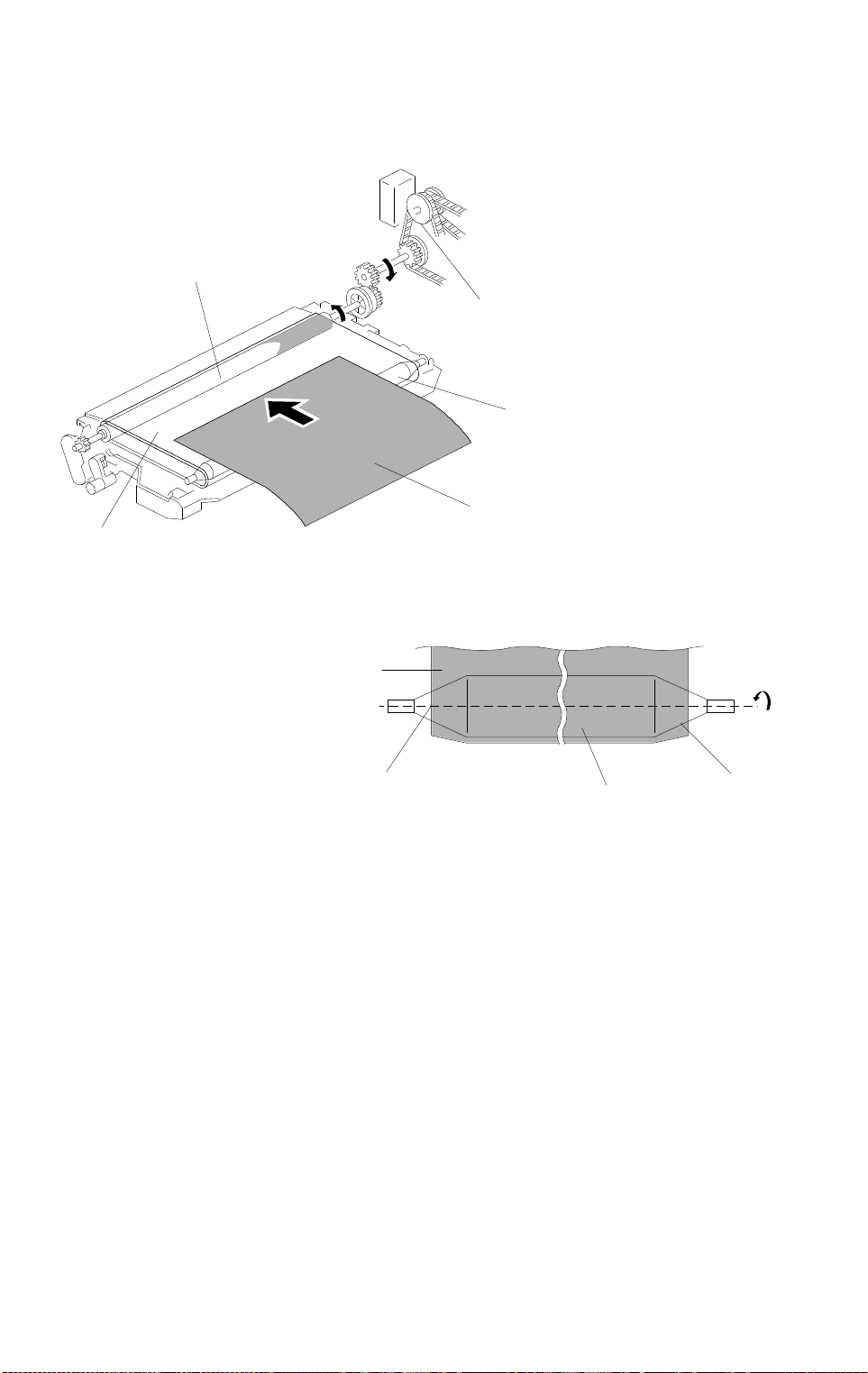
IMAGE TRANSFER 15 July 1996
5.5 PAPER TRANSPORTATION AND BELT DRIVE
MECHANISM
[C]
[A]
[E]
[B]
[F]
A176D577.wmf
[F]
[D]
[E]
[D]
A176D578.wmf
The transfer belt is driven by the main drive motor [A] through belt and gears.
Since the transfer belt electrically attracts the paper [B], the transport fan is
not required.
The charge on the transfer belt is discharged by the discharge plate to
reduce paper attraction and paper is separated by the paper stiffness above
the transfer belt drive roller [C] where the transfer belt is turning.
The tapered parts [D] at both sides of the roller [E] help keep the transfer belt
[F] at the center position.
2-64
Page 93

15 July 1996 IMAGE TRANSFER
5.6 TRANSFER BELT CLEANING MECHANISM
[D]
[A]
A176D579.wmf
[B]
A176D580.wmf
[C]
A176D581.wmf
Some toner may adhere to transfer belt when paper jams occur, or when the
by-pass feed table side fences are set in the wrong position causing the
erase lamp to miss some toner. The adhered toner must be removed to
prevent the rear side of the copy paper from being stained.
The cleaning blade [A] scrapes off any toner remaining on the transfer belt.
A counter blade system is used for the transfer belt cleaning. The surface of
the transfer belt is coated to make it smooth and so prevent the cleaning
blade from being flipped by the transfer belt.
Detailed
Descriptions
The lever [B] on the front end of the cleaning blade releases the cleaning
blade when the transfer belt unit is lowered and the lever is pushed by the
transfer belt unit support prop. (The transfer belt unit is lowered when the
lever [C] is turned anti-clockwise)
When the cleaning blade is released, the edge of the cleaning blade rubs the
seal so that the seal [D] removes the toner or paper dust on the cleaning
blade edge.
2-65
Page 94

IMAGE TRANSFER 15 July 1996
5.7 TONER COLLECTION MECHANISM
[B]
[A]
A176D582.wmf
Through idle gears [A], transfer belt drive is transmitted to the toner collection
coil [B]. The toner collection coil transports the collected toner to the toner
collection bottle. See section 2.2.5 for details.
2-66
Page 95

15 July 1996 PAPER FEED
6. PAPER FEED
6.1 OVERVIEW
[B]
[A]
[A]
[B]
[C]
A176D583.wmf
This model has three or four drawer tray paper feed stations.
The following table shows the configuration of each feed stations of the
copiers.
Feed station A175 copier A176/177 copiers A191/A192 copiers
1st
2nd
3rd 550 sheets tray 1500 sheets built-in L CT 550 sheets tray
4th 550 sheets tray — 550 sheets tray
550 sheets tra y 500 + 500 sheets
tandem feed tray
550 sheets uni versal tray 550 sheets universal
tray
500 + 500 sheets
tandem feed tra y
550 sheets univ ersal
tray
Detailed
Descriptions
Paper can also be fed using the by-pass feed table which has an
independent feed mechanism. The by-pass feed table can hold 50 sheets of
paper.
All feed stations use an FRR feed system. Rotation of the pick-up roller [A]
drives the top sheets of paper from each tray to the feed [B] and the
separation [C] rollers. The feed and separation rollers then take over paper
drive. If more than one sheet is fed by the pick-up roller, the separation rollers
rotates in the opposite direction and prevents all but the top sheet from
passing through to the registration rollers.
2-67
Page 96

PAPER FEED 15 July 1996
6.2 FRR FEED SYSTEM
[B]
[A]
[C]
A184D584.img
This copier uses an FRR paper feed system using three rollers.
6.2.1 Pick-up Roller
The pick-up roller [A] is not in contact with the paper stack before it starts
feeding paper. Shortly after the Start key is pressed, the pick-up roller drops
down and feeds the top sheet between the feed [B] and the separation rollers
[C]. At almost the same time that the paper’s leading edge arrives at the feed
roller, the pick-up roller lifts off the paper stack so that it does not interfere
with the operation of the feed and separation rollers. The feed and separation
rollers then take over the paper feed process.
6.2.2 Feed and Separation Rollers
There is a one-way bearing inside the feed roller so it can turn only in one
direction. The separation roller is driven in the opposite direction to the feed
roller. The separation roller, however, is driven through a slip clutch (torque
limiter clutch) which allows it to turn in either direction depending on the
friction between the rollers. The separation roller solenoid keeps the
separation roller in contact with the feed roller.
2-68
Page 97

15 July 1996 PAPER FEED
F2
F2
F1
[B]
F1
[A]
F2
F3
F3 F1
[B]
F1
[A]
A76D585.img
The direction in which the separation roller [A] turns depends on the frictional
forces acting on it. The slip clutch applies a constant clockwise force (F1).
When there is a single sheet of paper being driven between the rollers, the
force of friction between the feed roller [B] and the paper (F2) is greater than
F1. So, the separation roller turns counterclockwise.
If two or more sheets are fed between the rollers, the forward force on the
second sheet (F3), becomes less than F1 because the friction between the
two sheets is small. So, the separation roller starts turning clockwise and
drives the second sheet back to the tray.
Detailed
Descriptions
2-69
Page 98

PAPER FEED 15 July 1996
6.3 SLIP CLUTCH MECHANISM
A176D586.wmf
[A]
[G]
[D]
[B]
[E]
[F]
[C]
A176D587.img
The slip clutch [A] consists of the input hub [B] and the output hub [C] which
is the case of the clutch as well. The magnetic ring [D] and the steel spacers
[E] are fitted onto the input hub. The ferrite ring [F] is fitted into the output
hub. Ferrite powder [G] packed between the magnetic ring and the ferrite ring
[F] generates a constant torque due to magnetic force. The input hub and the
output hub slip when the rotational force exceeds the constant torque.
This type of slip clutch does not require lubrication.
2-70
Page 99

15 July 1996 PAPER FEED
6.4 FRR FEED DRIVE MECHANISM
[D]
[K]
[C]
[L]
[J]
Detailed
Descriptions
[B]
[A]
A176D588.wmf
[D]
[G]
[F]
[B]
[E]
[H]
[I]
A176D589.wmf
The rotation of the paper feed motor [A] is transmitted to the gear [B] via the
timing belt [C], and then transmitted to the separation roller via the feed
clutch gear [D], gear [E], gear [F] and gear [G].
If the paper feed station is not selected, the separation roller solenoid [H]
de-activates and the separation roller [I] rotates freely in the reverse direction
of paper feeding.
Gear [B] also transmits the drive to the vertical transport roller [J] via gear [D],
idle gear [K] and gear [L].
2-71
Page 100

PAPER FEED 15 July 1996
[A]
[F]
[D]
[B]
[C]
[E]
[G]
A176D589-2.wmf
[I]
[H]
A176D590.wmf
When the paper feed station is selected and the start key is pressed, the feed
clutch [A], separation roller solenoid [B], and the pick-up solenoid [C] turn on
at once.
When the feed clutch [A] activates to rotate the feed roller [D], the feed roller
and the pick-up roller [E] turn together because they are linked by the idle
gear [F].
When the separation roller solenoid [B] turns on, the separation roller [G]
contacts the feed roller [D] then rotates together with the feed roller in spite of
the separation roller’s drive in the opposite direction due to the torque limiter
function in the separation roller [G].
When the pick-up solenoid [C] activates, the pick-up roller [E] lowers to make
contact with the top sheet of the paper stack and send it to the feed and
separation rollers.
When the paper feed sensor [H] detects the leading edge of the paper [I], the
pick-up solenoid de-energizes to lift the pick-up roller and the paper feed
clutch de-energizes at a certain time to wait until it is ready to feed to the
registration roller.
2-72
 Loading...