

Page 1
RICOH
RICOH COMPANY, LTD.
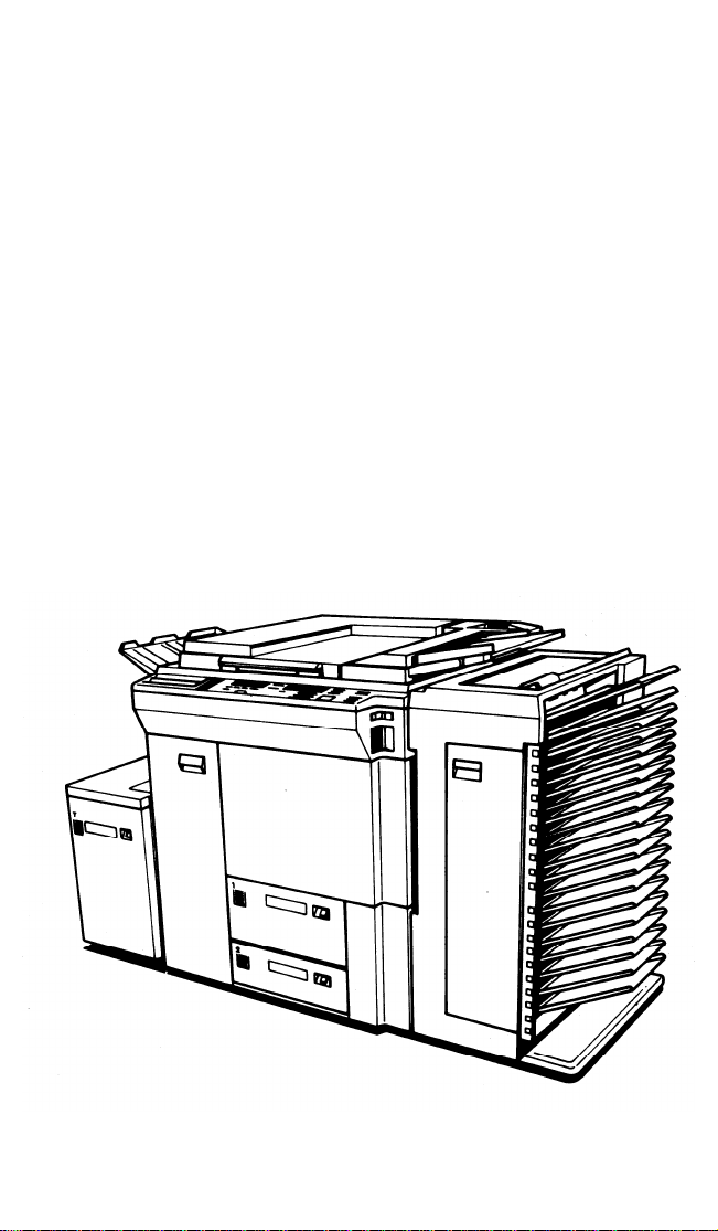
RICOH FT7060
FIELD SERVICE
MANUAL
Page 2

I. INSTALLATION
1.
Environment
2.
Minimum Space Requirements
Machine Level
3.
4.
Power Source
Unpacking and Installation
5.
6.
Key Counter Holder Installation
7.
A3 / 11” x 17” Counter Installation
8.
Modifying Main Transformer Voltage (220V to 240V)
9.
Preparation for Transporting the Copier . . . . . . . . . . 1-18
II. SERVICE TABLES
TABLE OF CONTENTS
1-1
1-2
1-3
1-3
1-4
1-15
1-16
1-17
PM TABLE
SERVICE TABLES
1. Test Points
2. Variable Resisters . . . . . . . . . . . . . . . . . . . . . . . . . . . . . 2-6
3. Dip Switches
SERVICE REMARKS
SPECIAL TOOLS AND LUBRICANTS . . . . . . . . . . . . . . . . . . . . . . . . 2-12
III. REPLACEMENT AND ADJUSTMENT
EXTERIOR COMPONENT REMOVAL
1.
Exposure Glass and Operation Panel Removal
2.
Top Plate Removal
DRUM
AND CHARGE
Drum Replacement 3-3
3.
4.
Drum Thermoswitch and Heater Replacement
Charge Corona Wire Replacement
5.
Charge Cleaner Drive Wire Replacement
6.
EXPOSURE
7. Scanner Drive Wire Replacement
8. Lens Drive Wire Replacement
9. Exposure Lamp Unit Removal
DEVELOPMENT
10. Development Unit Removal
11. Developer Replacement
12. Development Roller and Paddle Roller Removal . . 3-24
13. Adjustment of Development Roller Gaps
14. Image Density Sensor Cleaning and Removal
15. Image Density Sensor Adjustment
2-1
2-5
2-6
2-7
3-1
3-2
3-4
3-5
3-6
3-7
3-17
3-21
3-22
3-23
3-26
3-28
3-29
Page 3

TRANSFER AND PICK-OFF
16. Transport Unit Removal
17. Pre-transfer Corona Wire Replacement
18. Transfer and Separation Corona Wire Replacement
19. Drive Wire Replacement (PTC and T/S Corona) . . .
20. Transport Belt Replacement
21. Registration Sensor Replacement
22. Pick-off Pawl Unit Removal . . . . . . . . . . . . . . . . . . . .
CLEANING
23. Cleaning Blade and Brush Replacement
24. Pre-cleaning Corona Wire Replacement
25. Toner Collection Coil Replacement
26. Cleaning Blade Pressure Adjustment
27. Blade Cleaner and Bias Roller Blade Replacement
28. Pre-quenching Corona Wire Replacement
FUSING
29.
Fusing Unit Removal
Hot Roller Stripper Replacement
30.
Cleaning Blade, Metering Blade,
31.
and Oil Supply Pad Replacement
32.
Hot Roller Replacement
33.
Pressure Roller Replacement
34.
Thermistor and Thermofuse Replacement
Fusing Pressure Adjustment
35.
Hot Roller Temperature Adjustment
36.
INVERTER
37. Inverter Roller Clutch Disassembly
and Adjustment
38. Inverter Gate Solenoid Adjustment
39. Inverter Gate Adjustment
3-30
3-31
3-32
3-33
3-34
3-35
3-36
3-37
3-38
3-39
3-40
3-41
3-42
3-43
3-44
3-45
3-47
3-49
3-50
3-51
3-53
3-54
3-56
3-57
PAPER FEED
40. Paper Feed Unit Removal
41. Pick-up Roller Replacement
42. Feed Roller Replacement
43. Friction Roller Replacement
44. Paper Tray Unit and Cover Removal
45. Paper Tray Drive Wire Replacement . . . . . . . . . . . . .
46. Vertical Transport Unit Removal
DUPLEX TRAY
47.
Duplex Tray Removal
Paper Feed Roller Replacement and Adjustment . . 3-68
48.
49.
Pick-up Roller Replacement
Friction Roller Replacement . . . . . . . . . . . . . . . . . . . 3-70
50.
Bottom Plate Pressure Clutch Disassembly
51.
Duplex Paper Sensor Adjustment . . . . . . . . . . . . . . . . 3-72
52.
Duplex Side Plate Drive Wire Replacement
53.
3-58
3-59
3-60
3-61
3-62
3-63
3-66
3-67
3-69
3-71
3-73
Page 4

COPY IMAGE
54. Horizontal Magnification Adjustment
55. Side-to-Side Registration Adjustment
56. Uneven Exposure Adjustment
57. Light Intensity Adjustment
58. Auto Density Sensor Adjustment
3-74
3-75
3-76
3-77
3-78
CORONA CURRENT ADJUSTMENT
59. Corona Current Adjustment Preparation
60. Charge Corona
61. Pre-transfer Corona . . . . . . . . . . . . . . . . . . . . . . . . . . . 3-82
62. Transfer Corona
63. Separation Corona
64. Pre-cleaning Corona
65. Pre-quenching Corona
SERVICE PROGRAM MODE
1. Factory Settings
2. Service Program Functions
IV. ELECTRICAL DATA
Main Board Schematic
1.
2.
DC Drive Board Schematic . . . . . . . . . . . . . . . . . . . . . . 4-2
Scanner Motor Control Board Schematic . . . . . . . . . . 4-2
3.
4.
Main Motor Control Board Schematic . . . . . . . . . . . . . 4-3
Lens/Mirror Motor Control Board Schematic . . . . . . 4-4
5.
6.
Timer Board Schematic
7.
Power Supply Unit Block Diagram
Operation Panel - CPU Board Schematic . . . . . . . . . . 4-7
8.
Operation Panel - CPU Board Schematic
9.
10.
AC Drive Board Schematic
11.
DF Main Board Schematic
Sorter Main Board Schematic
12.
3-79
3-81
3-83
3-84
3-85
3-86
3-87
3-88
4-1
4-5
4-6
4-8
4-8
4-10
V. DOCUMENT FEEDER
SERVICE TABLES
1. Test Point Table
2. Variable Resister Table . . . . . . . . . . . . . . . . . . . . . . . 5-1
3. LED Table
4. DIP Switch Table
5. Blown Fuse Table
6. Switch Failure Table
7. Sensor Failure Table
5-1
5-1
5-2
5-3
5-3
5-4
Page 5

REPLACEMENT AND ADJUSTMENT
1.
Separation Roller Replacement
2.
Friction Tab Replacement
Pick-up Roller Replacement
3.
4.
Transport Unit Cover Removal
5.
Feed Belt Removal
6.
Inverter Entrance and inverter Registration
Sensor Replacement
7.
Turn Roller Replacement
8.
Exit Roller/Pull-out Roller Replacement
Inverter Roller Replacement
9.
10.
DF Removal
11.
12.
VI. SORTER
Original Skew Adjustment
Original
Leading Edge Adjustment
5-5
5-6
5-7
5-10
5-11
5-12
5-13
5-14
5-15
5-17
5-18
5-19
UNPACKING
INSTALLATION
1. Accessory Check
2. Installation Procedure . . . . . . . . . . . . . . . . . . . . . . . . 6-3
SERVICE TABLES
1. Sorter Main Board
2. Sorter Interface Board
REPLACEMENT AND ADJUSTMENT
1. Distribution Unit Removal . . . . . . . . . . . . . . . . . . . . . 6-8
2. Transport Unit Removal
3. Transport Belt Replacement . . . . . . . . . . . . . . . . . . . . 6-11
4. Jam Sensor and Bin Copy Sensor Adjustment . . . . . 6-14
5. 50Hz/60Hz Modification
VII. LARGE CAPACITY TRAY
UNPACKING
INSTALLATION
1. Accessary Check
2. Installation Procedure . . . . . . . . . . . . . . . . . . . . . . . . 7-3
REPLACEMENT AND ADJUSTMENT
1. Paper Feed Unit Removal
2. Pick-up Roller Replacement
3. Feed Roller Replacement
4. Friction Roller Replacement
5. Paper Tray Unit Removal
6. Paper Tray Drive Wire Replacement
6-1
6-2
6-6
. . . . . . . . . . . . . . . . . . . . . . . . 6-7
. . . . . . . . . . . . . . . . . . . . . . . . 6-10
. . . . . . . . . . . . . . . . . . . . . . . . 6-15
7-1
7-2
7-7
7-8
7-9
7-10
7-11
7-12
Page 6

INTRODUCTION
COPY QUALITY
White Spots
Hat Image
Blank Area
Wrinkled Copy
Unfused Copy
Horizontal White Lines (Bands)
Jitter
Hollowing Out
Fuzzy Copy
Vertical White Lines (Bands)
Uneven Density
Vertical Black Lines (Bands)
Black Spots
Dirty Background
Black Image
Blank Copy
Light Copy
PAPER JAM/MISFEED
Pick-off Jam
False Paper Jam
Duplex Tray Jam
Paper Feed Jam
Registration Jam
Exit Jam
Transport Unit Jam
Fusing Jam
8-1
8-2
8-3
8-4
8-5
8-6
8-6
8-7
8-8
8-8
8-9
8-11
8-14
8-18
8-19
8-22
8-22
8-24
8-26
8-27
8-27
8-29
8-30
8-30
8-30
8-31
FUNCTIONAL PROBLEM
Not Ready
Abnormal Indications . . . . . . . . . . . . . . . . . . . . . . . . . . . . . . . 8-32
Please Wait Condition
DF
Original Jam
No Display
Abnormal Indication . . . . . . . . . . . . . . . . . . . . . . . . . . . . . . . . 8-36
SORTER
Not Ready
False Jam . . . . . . . . . . . . . . . . . . . . . . . . . . . . . . . . . . . . . . . . . . 8-37
Jam in Sorter 8-38
Others
8-32
8-34
8-35
8-35
8-37
8-38
Page 7

SERVICE CALL
SC - l
- 2
- 3
- 4
- 5
- 6
- 7
- 8
- 9
- l0
- 11
- 12
- 13
- 14
- 15
- 17
- 18
- 19
- 21
- 22
- 23
- 24
- 25
DEFECTIVE SENSOR TABLE
Table 8-60
CONDITIONS
Exposure
Drum Thermistor
Drum Heater
Drum Overheat
Fusing Thermistor
Fusing Lamp
Fusing Overheat
Temperature Fuse . . . . .
Optics Encode
Home Sensor . . . . . . . . . . . . . . . . . . . . . . . . . . . . 8-48
Scanner Velocity
Scanner Return
Total Counter
High Voltage Leak
Lens Drive Lock
Cleaner Motor - Charge Wire
Cleaner Motor - PTC Wire . . . . . . . . . . . . . . . 8-54
Cleaner Motor
Paper Feed Unit
Option Tray Paper Feed Unit
Upper Tray
Lower Tray
Option Tray
. . . . . . . . . . . . . . . . . . . . . . . . 8-41
. . . . . . . . . . . . . . . . . . . . . . 8-44
. . . . . . . . . . . . . . . . . . . . . . . . 8-45
. . . . . . . . . . . . . . . . . . . 8-46
. . . . . . . . . . . . . . . . . . . . . . . . 8-50
. . . . . . . . . . . . . . . . . . . . . . 8-51
. . . . . . . . . . . . . . . . . . . . . 8-52
- T/S Wire
. . . . . . . . . . . . . . . . . . . . . . . . 8-56
. . . . . . . . . . . . . . . 8-55
8-39
8-42
8-43
8-44
8-47
8-49
8-50
8-53
8-56
8-57
8-58
8-59
Page 8

SECTION 1
INSTALLATION
Page 9

CONTENTS
Environment . . . . . . . . . . . . . . . . . . . . . . . . . . . . . . . . . . . . . . . .
1.
2.
Minimum Space Requirements
Machine Level
3.
4.
Power Source . . . . . . . . . . . . . . . . . . . . . . . . . . . . . . . . . . . .
Unpacking and Installation
5.
Key Counter Holder Installation
6.
7.
A3 / 11” x 17” Counter Installation
8.
Modifying Main Transformer Voltage (220V to 240V) . .
Preparation for Transporting the Copier
9.
12 July ’86
1-1
1-2
1-3
1-3
1-4
1-15
1-16
1-17
1-18
Page 10

1. Environment
12 July ’86
1. Temperature Range
10°C to 30°C (50°F to 86°F)
2. Humidity Range 15% to 90% RH
3. Ambient Illumination Less than 1,500 lux (Do not expose to direct sunlight.)
4. Ventilation Room air should turn over at least 3 times/hour.
5. Ambient Dust Less than 0.15 mg/m
3
6. Room Size More than 10 m
(13.4 yd3)
3
(4 x 10
-3
Oz/yd3)
7. If the place of installation is air-conditioned or heated, place the
machine:
a) where it will not be subjected to sudden temperature changes from
low to high, or vice versa.
b) where it will not be directly exposed to cool air from an air con-
ditioner.
c) where it will not be directly exposed to reflected heat from a
heater.
8. Avoid placing the copier in an area filled with corrosive gas.
9. Avoid any area higher than 2,000 m (6,500 feet) above sea level.
10. Place the copier on a strong and level base,
NOTE: This copier weighs 290 kg (638 lb). Before installing, make sure
that the floor is strong enough for this machine.
This is especially required when there is other heavy equipment located
nearby.
11. Avoid any area where the copier may be subjected to strong vibration.
1-1
Page 11
12 July ’86
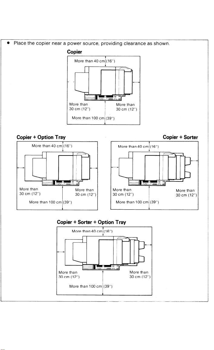
2. Minimum Space Requirements
1-2
Page 12
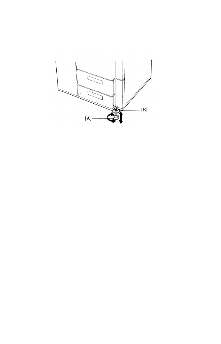
3. Machine Level
12 July ’86
1.2.Front to Back:
Right to Left:
Place the four leveling shoes [A] under the leveling feet [B] and screw
the leveling feet up or down to level the machine.
4. Power Source
Input Voltage Level
1.
115V/60 Hz - 20A
220V/50 Hz - 10A
240V/50 Hz - 10A
Permissible Voltage Fluctuation : ± 10%
2.
3.
Permissible Extension Cord: None recommended
NOTE: - Be sure to ground the machine.
wire to a gas pipe.)
- Make sure the plug is firmly inserted in the outlet.
- Should be dedicated outlet.
- Do not set anything on the power cord.
Within 5 mm (0.2”) of level
Within 5 mm (0.2”) of level
(Do not connect the grounding
1-3
Page 13

12 July ’86
5.
Unpacking and Installation
- Unpacking -
1.
Cut the bands [A] binding the carton and remove the top carton [B].
2.
Take out the accessories [C].
Remove the cushion blocks [D].
3.
4.
Open the vinyl bag.
5.
Take out the machine.
1-4
Page 14

- Accessory Check -
12 July ’86
Check the quantity
the New Equipment
DESCRIPTION
1)
Copy Tray
2)
Original Tray
3)
Screw M4 X 8 mm
4)
Leveling Shoe
5)
Cushion Block
6)
Operating Instructions
7)
Installation Procedure
8)
N.E.C.R.
9)
Envelope for N.E.C.R.
10)
Multiple Language Decals (Europe)
and condition of the accessories in the box according to
Condition Report (NECR) or the following list:
(U. S. A.)
Q’TY
1
1
2
4
2
1
1
1
1
1
1-5
Page 15

12 July ’86
- Installation Procedure -
1. Remove all external strips of tape [A] and the two sponge door cushions
[B].
2. Remove the lower right cover [C] (3 screws) and the two studs [D] securing the paper trays. Reinstall the lower right cover.
3. Open the left door, and remove the two strips of tape [E] securing the
vertical transport guide plate.
4. Open the right
sponge cushions
door.
[F].
Pull out the paper trays and remove the three
1-6
Page 16
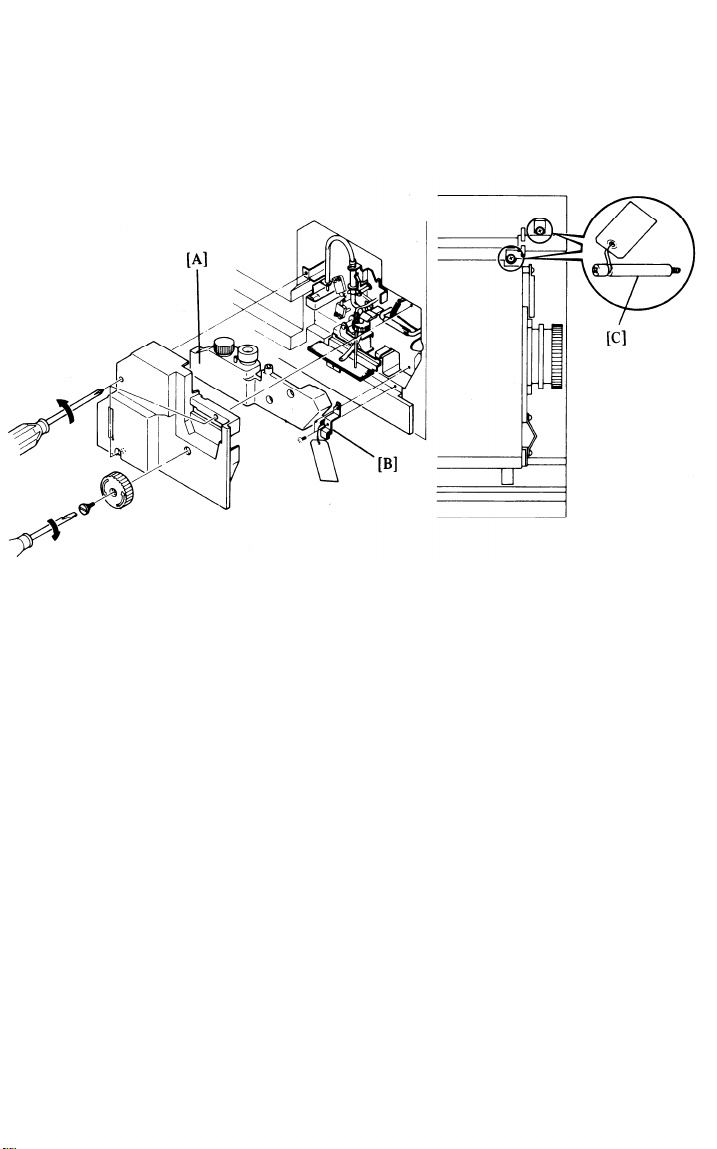
12 July ’86
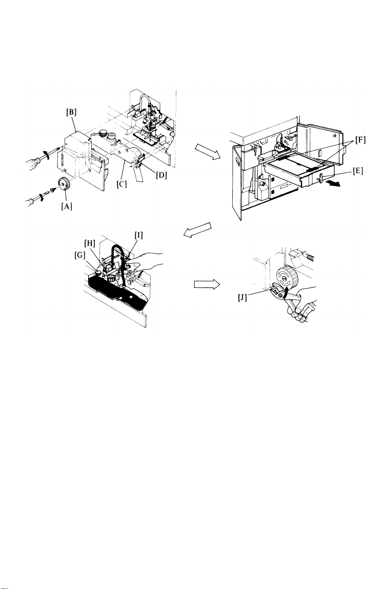
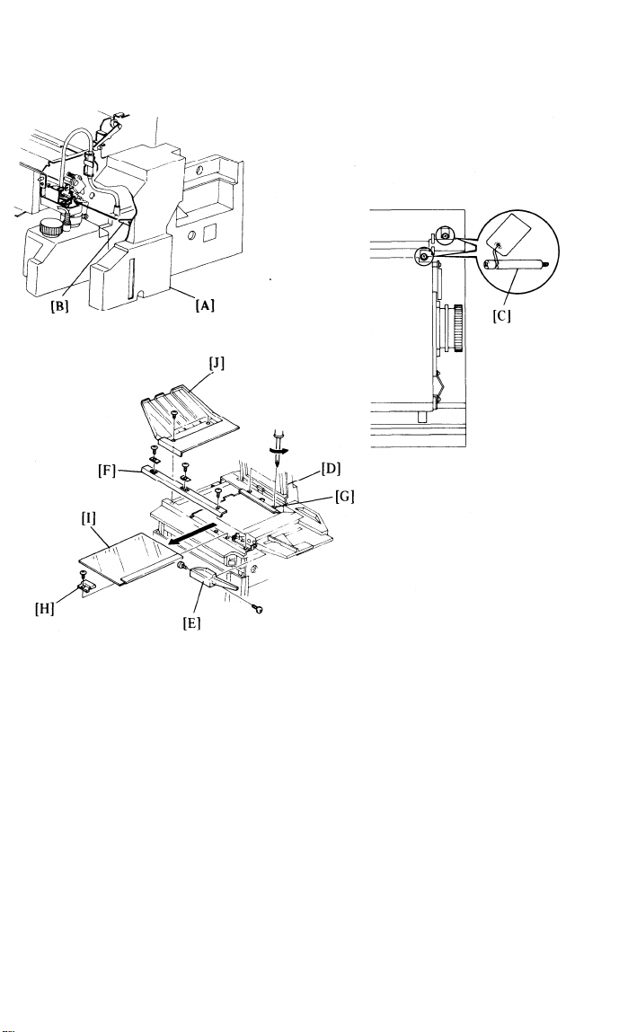
5. Open the top unit, then remove the fusing knob [A] (1 screw: reverse
thread), cover [B] (3 screws), and the oil bottle [C]. Remove the clamp
[D] (2 screws) which secures the fusing unit and the duplex tray.
6. Turn the duplex tray handle [E] to the horizontal position, pull out the
duplex tray, and remove the two strips of tape [F] securing
the duplex
unit covers. Open the duplex unit covers and carefully remove the strip
of tape securing the bottom plate. Then reset the duplex unit.
7. Unscrew the oil bottle cap [G], and fill the oil bottle with silicone oil.
Do not overfill the bottle. Reinstall the cap. Confirm that oil is supplied
to the oil sump [H] by pressing the oil supply lever [I] against the sleeve
of the oil pump several times.
8. Rotate the pressure cam shaft [J] counterclockwise until it locks (about
90°) to apply the pressure between the hot roller and the pressure
roller.
1-7
Page 17
12 July ’86
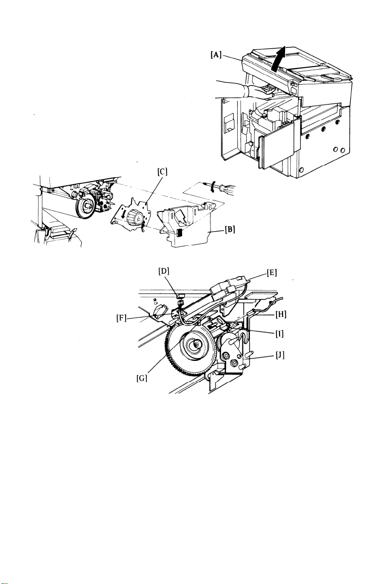
9.
Reinstall the fusing unit cover [A] and the fusing knob. Confirm that the
tab [B] on the inside of the cover lifts up the oil sump stopper. If it
does not, oil will overflow from the sump. Close the top unit.
10.
Remove the two optics studs [C] as follows:
Raise the DF transport unit [D].
a)
b)
Remove the front cover [E] of the original feed unit (2 screws).
c)
Remove the front top cover [F] (3 screws).
d)
Loosen the two screws of the rear scale [G], and remove the glass
fixing plate [H] (1 screw).
e)
Remove the exposure glass [I].
f)
Remove the two optics studs securing the lens housing and the first
scanner.
Reassemble.
g)
Install the original tray [J] (2 screws: M4 x 8 mm).
11.
1-8
Page 18
12 July ’86
1-9
12.
Open the top unit [A], and remove the drum cover [B] (2 screws).
13.
Remove the drum stay [C] by turning the knob counterclockwise.
Disconnect the charge corona wire cleaner connector [D] and remove the
14.
charge corona unit [E].
Pull out the erase unit [F] and the drum thermistor [G].
15.
Disconnect the pre-quenching corona wire cleaner connector [H], and
16.
remove the quenching lamp unit [I].
17.
Remove the cleaning unit [J].
Page 19
12 July ’86
I
CAUTION: Do not leave the top unit open, exposing an uncovered drum, for long
periods.
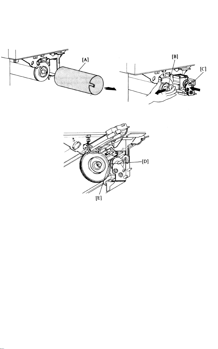
18.
Remove the drum protective sleeve [A] from the drum. Save the drum
protective sleeve for future use.
19.
Pressing the drum shaft [B] to the left to prevent drum damage, reinstall
the cleaning unit [C]. The cleaning unit must be inserted until the
cleaning unit drive gear [D] engages with the drum flange gear [E].
Reinstall the erase unit, the drum thermistor, the quenching lamp unit,
20.
and pre-quenching corona unit.
Reconnect the pre-quenching corona
wire cleaner connector.
21.
Reinstall the charge corona unit and reconnect the charge corona wire
cleaner connector.
22.
Reinstall the drum stay and the drum cover.
1-10
Page 20
12 July ’86
23. Prepare the development unit as follows:
Remove the development unit cover [A] (1 screw).
a)
b)
Remove the development unit [B] by removing the development unit
mounting screw [C] and place the unit on a sheet of paper.
Remove the developer inlet cover [D].
c)
d)
Pour two kilograms of developer into the development unit. While
pouring in the developer, turn the paddle roller knob [E] clockwise to
evenly distribute the developer.
Reinstall the developer inlet cover and the development unit.
e)
NOTE: Confirm that the development unit is seated on the guide rails
properly. Also, confirm that the development unit is set cor-
rectly.
If not, pull the unit out slightly, turn the paddle roller
knob, and push the unit back in.
1-11
Page 21
12 July ’86
CAUTION:
Always lower the top unit [A] before tightening the development unit
mounting screw [B]. The slot [C] on the top unit fits over the positioning pin [D] on the development unit to correctly position the development unit.
f) Close the top unit, and secure the development unit (1 screw).
g) Open the top unit again and reinstall the development unit cover.
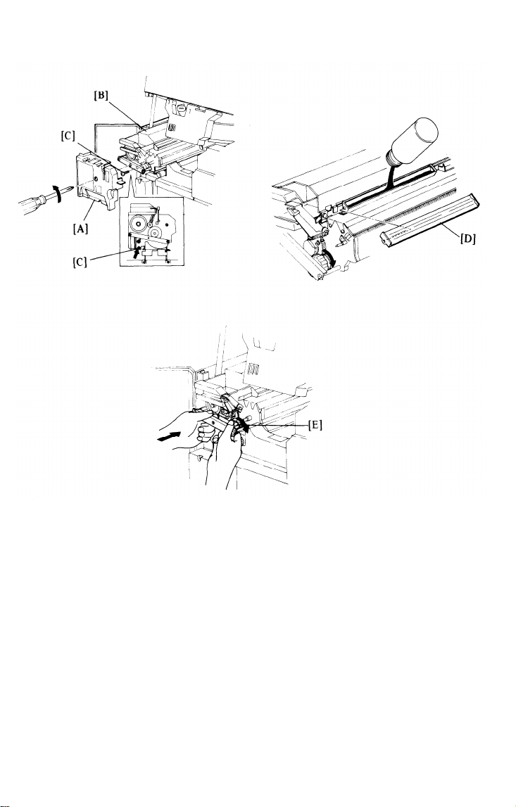
24, Load a toner cartridge [E] as follows:
a)
Hold a new toner cartridge level and shake it well.
b)
Turn down the toner cartridge lever [F].
c)
Insert a new toner cartridge and raise the toner cartridge lever.
(Only load one toner cartridge.)
d)
Cut the green tape and push down the latch on the shutter plate.
Then, pull the shutter plate all the way out.
e)
Hold the green tab and pull the toner seal out as far as it will go.
Push the shutter plate back in completely.
f)
Close the top unit.
g)
1-12
Page 22
12 July ’86
25.
Remove the lower
connector [A] on the
26.
Close the front doors and plug in the power cord. Turn on the main
left cover (2 screws), and move the jumper
timer board from JPS-102 to JPS-101.
switch [B].
While waiting for the fusing unit to warm up (about
27.
7 minutes), install
the copy tray [C].
28.
Load paper in the upper and lower paper trays.
29.
Perform drum conditioning for 15 minutes as follows:
a) Place a white sheet of A3 or 11” x 17” paper on the exposure glass
and lower the ADF transport unit.
b) Use SP 1-3 (Free Run) for
30.
Insert the sponge cushions
drum conditioning.
under the base plate of the copier at the
[D]
front and rear.
1-13
Page 23

12 July ’86
31. Set up the following items according to the customer’s requirements.
Refer to Section 3 for Service Program Mode.
SP No.
1-4
2-2
3-3
3-4
4-1
6-1
Item
Beeper Off
ID Reset Level
20 min. Fusing Timer
Copy Counter
ID Control Mode
Full Automatic DF
Feed Mode
8-2
Auto. Paper Selection. 26
10-3/4 Toner Supply Amount 28
20
32.
Set the weekly timer,
33.
Check copier and DF operation.
34.
Check copy quality. Adjust as necessary.
35.
Complete the N.E.C.R.
Automatic Reset Time
according to the customer’s request.
SP No.
21
22
23
24
25
Item
Max Copy Quantity
Magnification Ratio
Priority
Optional Magnification
Ratio
Auto. Shut-off Timer
Standard Timer Setting
EM Call Telephone No.
User Code
1-14
Page 24
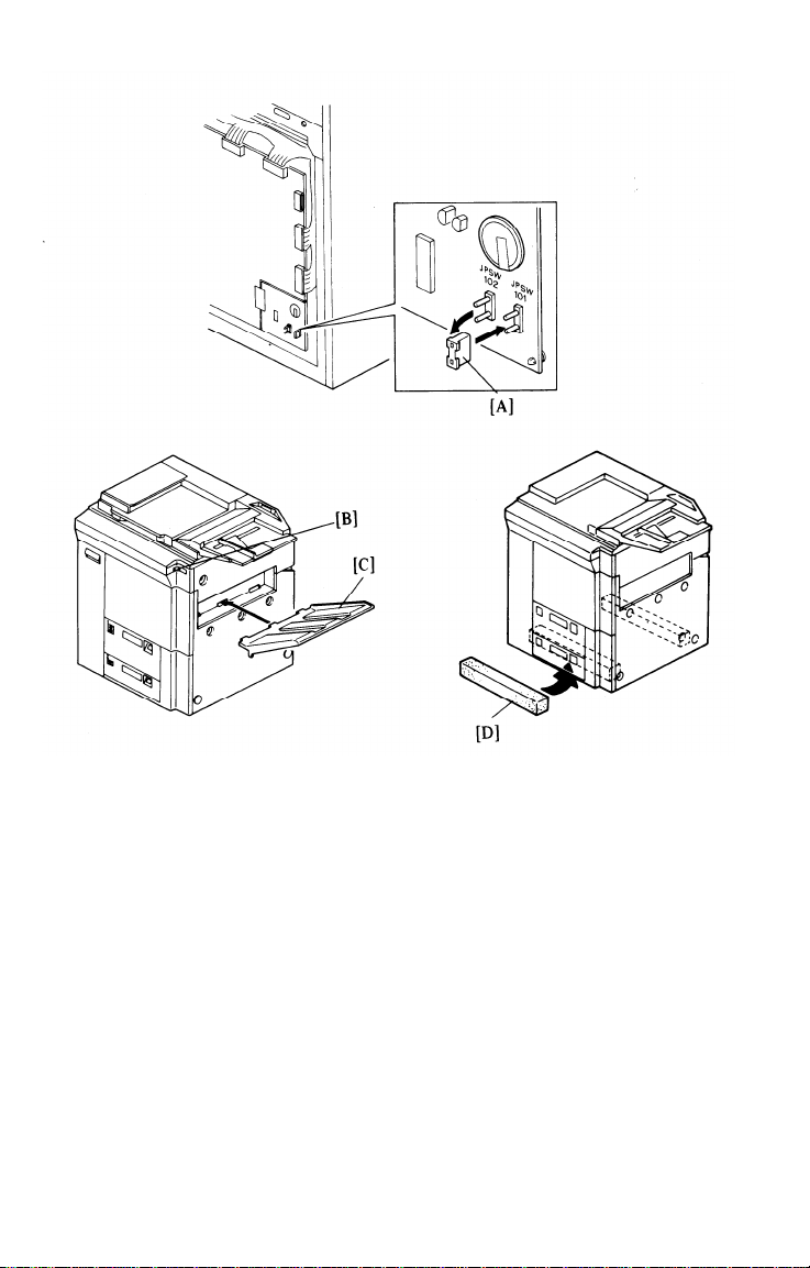
6. Key Counter Holder Installation
12 July ’86
Remove the upper front cover (2 screws).
1.
Remove the cover plate [A] and fixing plate [B] from the main switch
2.
bracket (2 screws).
Hold the fixing plate on the inside of the key counter holder and insert
3.
the key counter holder [C].
4.
Align the screw holes in the fixing plate with the mounting holes of the
key counter holder and secure the key counter holder.
NOTE: This copier can use three types of counters. Make sure to use the
correct screw holes in the fixing plate.
5.
Remove the shorting connector [D] from the key counter connector.
Connect the key counter holder.
6.
7.
Reassemble the copier and check key counter operation.
1-15
Page 25
12 July ’86
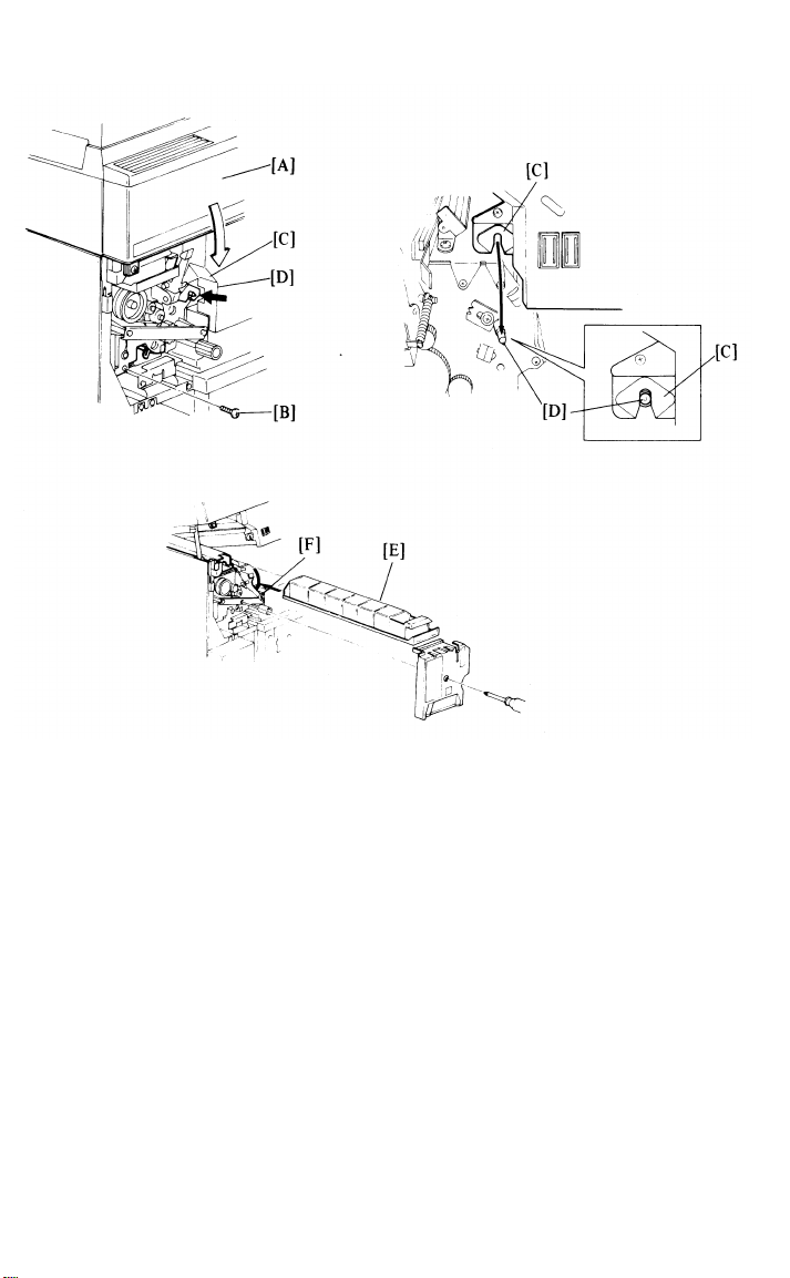
7. A3 / 11” x 17” Counter Installation
1.
Open the left door.
2.
Remove the development unit cover [A] (1 screw) and the jam indicator
cover [B] (3 screws).
3.
Remove the jam indicator bracket [C] (2 screws).
Disconnect the dummy connector from the A3 / 11” x 17” counter connec-
4.
tor [D].
Set the A3 / 11” x 17” counter [E] through the jam indicator bracket as
5.
shown.
Connect the A3 / 11” x 17” counter connector.
6.
Reassemble.
7.
Set SP 4-4 (A3 / 11” x 17” counter).
8.
9.
Check the counter operation by making an A3 / 11” x 17” copy.
1-16
Page 26
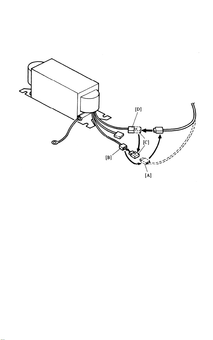
8. Modifying Main Transformer Voltage (220V to 240V)
12 July ’86
1. Remove the lower right cover (2 screws).
2. Disconnect the input line [A] from the 220 V connector [B].
3. Disconnect the dummy connector [C] from the 240 V connector [D].
4. Connect the input line to the 240 V connector.
5. Connect the dummy connector to the 220 V connector.
6. Reassemble.
1-17
Page 27
12 July ’86
1-18
9. Preparation for Transporting the Copier
CAUTION: Before transporting the copier, be sure to prepare it as follows. The copier
may be badly damaged if it is moved without proper preparation.
1. Select the 100% magnification ratio.
2. Remove the paper from the upper and lower paper trays.
3. Turn off the main switch and unplug the copier.
4. Remove the oil bottle [A] and empty it.
5. Secure the fusing unit and duplex tray with the clamp [B] as shown (2
screws) and reassemble.
6. Remove the exposure glass.
7. Fix the lens housing and the first scanner guide bracket with studs [C]
as shown.
8. Reassemble the machine.
Page 28
12 July ’86
1-19
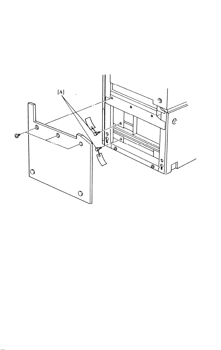
9.
Remove the lower right cover and fix the paper trays with studs [A].
Reinstall the lower right cover.
10.
Fix the DF,
11.
Remove the
12.
Remove the
13.
Remove the
left front door, and right front door with strips of tape.
copy tray or sorter.
original tray (2 screws).
option tray, if installed.
Page 29

SECTION 2
SERVICE TABLES
Page 30

CONTENTS
SPECIAL TOOLS AND LUBRICANTS
. . . . . . . . . . . . . . . . . . . . . . . .
12 July ’86
PM TABLE
SERVICE TABLES
1. Test Points . . . . . . . . . . . . . . . . . . . . . . . . . . . . . . . . . . . . 2-5
2. Variable Resisters . . . . . . . . . . . . . . . . . . . . . . . . . . . . . 2-6
3. Dip Switches
SERVICE REMARKS
2-1
2-5
2-6
2-7
2-12
Page 31

PM TABLE
12 July ’86
C: Clean R: Replace
Item
OPTICS
1. Mirrors, Lens
2. Exposure Glass
3. Reflector
4. Toner Shield
Glass
5. Exposure Lamp
6. Scanner Guide
Rods
7. Lens Drive Gear
8. Fan Filter
9. Exposure Damper
10. ADS
PAPER FEED UNIT
11. Feed Roller
12. Friction Roller
13. Pick-up Roller
14. Feed Sensors
15. Paper Guide
16. Tray Gear
L: Lubricate A: Add I: Inspect
EM
120K
240K
360K
c
c
c
c
c
C,L
c
c
c
c
c
c
c
c
c
c
c
c
C,L
c
c
R
R
R
c
c
c
c
c
c
c
c
C,L
c
c
c
c
c
c
c
480K
c
c
c
c
R
C,L
c
I,R
c
c
c
c
c
c
600K
c
c
c
c
c
C,L
L
c
c
c
c
c
c
c
L
c Alcohol/water
silicon cloth
c Glass cleaner
dry cloth
c Alcohol/water
silicon cloth
c
c
C,L
Launa 40 oil
or equivalent
L
Launa 40 oil
or equivalent
c
c
c Alcohol
c
Alcohol
c Alcohol
c Blower brush
c Dry cloth
Mobil Temp. 78
L
DUPLEX TRAY
17. Feed Roller
18. Friction Roller
19. Pick-up Roller
20. Drive Gears
21. Drive Chain
22. Pressure Clutch
VERTICAL TRANSPORT
AND REGISTRATION
23. Transport
Rollers
24. Guide Plates
25. Drive Gears
26. Drive Chain
27. Dust Catcher,
Roller
28. Registration
Sensor
29. Regist. Roller
30. Registration
Drive Gear
c
c
c
c
c
c
L
L
L
L
L
L
c
c
c
c
L
L
L
L
c
c
L
L
c
c
c
c
L
L
L
c
c
L
L
c
L
c
c
c
c
c
L
L
L
L
L
L
c
c
c
c
L
L
L
L
c
c
c
c
L
L
Alcohol/Water
R
R
Alcohol/Water
R
Alcohol/Water
L
Mobil Temp. 78
L
Mobil Temp. 78
L
Mobil Temp. 78
Alcohol/Water
c
c Dry cloth
L
Mobil Temp. 78
Mobil Temp. 78
L
c
Blower brush
Water
Mobil Temp. 78
L
2-1
Page 32

12 July ’86
C: Clean R: Replace
Item
TRANSPORT UNIT
31. Pick-off Sensor
32. Transport Belt,
Belt Rollers
33. Belt Drive Gear
34. Vacuum Tank
35. Vacuum Fan
Filter
36. Pick-off
Solenoid
DEVELOPMENT UNIT
37. Developer
38. Upper and Lower
Seals
39. Side Seals
40. Upper Cover
41. Gears
42. Inlet Cover
43. Belt, Pulley,
Plastic Gears
44. Bearings
45. Toner Supply
Clutch
46. Doctor Plate
L: Lubricate A: Add I: Inspect
120K
EM
240K 360K
C C C C C C
C C C C C
L L L L L
C C C C C
R R
I I I I I
R R
C C C C C C
I I I I I I
C C C C C
C C C
C C C C C
C C C C C
I
C
480K 600K 1.2M
R
R R
R
R R
C
I I,R
C
C
C C
NOTE
Blower brush
I,R Alcohol/Water
L
Mobil Temp. 78
C
Water
R
I
R
C
C
C
C
AROUND DRUM
47. Drum
48. Pick-off Pawls
49. PQC Wire
50. CC Wires
51. PTC Wire
52. TC/SC Wires
53. Wire Cleaner
Pads
54. Quenching Lamp
55. Erase Lamp Unit
56. Drum Thermistor
Unit
57. Corona Casings,
End Blocks
58. TC Casing
Cleaner Pads
59. Brush Seal
60. Image Density
Sensor
61. Charge Corona
Fan Filter
I I I I I
C C C C C
R
C
R R
*
R
R
R
C
C
R R R R
C
R R
C
R
C
C
C
C C C C C C
C C C C C C
R
R R R R R
*
R
C C C C C C
C C C C C C
R R R
C C C C C
C C C C C
C C C C C
2-2
C
R R
R R
*
R
I
Replace if
necessary
C
R
Dry Cloth
Dry Cloth
Dry Cloth
Dry Cloth
R
* Upside Down
Damp Cloth
Damp Cloth
C
C
Damp Cloth
C
Blower Brush
C
Check VSG
C
Page 33

12 July ’86
2-3
C: Clean R: Replace
Item
FUSING UNIT
62. Hot Roller,
Bearing
63. Pressure Roller
Bearing
64. Metering and
Cleaning Blades
65. Oil Pad
66. Pressure and
Hot Roller
Strippers
67. Cleaning Roller
68. Thermistor
69. Paper Guides
70. Terminal Screws
71. Inverter Roller
Clutch
72. Silicone Oil
73. Fusing Exhaust
Fan Filter
74. Cleaning Roller
Bushing
75. Inverter
Rollers
76. Gears, Chains,
Levers, Pins
L: Lubricate A: Add I: Inspect
EM
120K
240K
C
C
C
C
C
R
R
R
C
C
C
C
C
C
C
I
I
L
A
A
A
R
R
C
C
L
L
480K
R
C
C
R
C
R
C
C
C
I
A
R
C
L
C
R
R
C
C
C
C
I
L
A
R
I,R
C
L
C
C
R
C
C
C
I
A
R
C
L
1.2M
NOTE
C
C
R
R
W/Si Oil
Suitable
C
solvent
C
Alcohol only
C
C
Tighten
I
Mobil Temp 78
L
A
R
C
Mobil Temp 78
L
CLEANING UNIT
77. Cleaning Blade
78. Blade Swing Pin
79. Cleaning Brush
80. Bevel Gears
81. Blade Cleaner
82. Seals
83. Cleaning Unit
84. Toner Catcher
85. Bias Roller
Blade
86. PCC Wire
87. Toner
Receptacle
I,C
C
R
L
R
C
I,C
C
C
C
C
R
L
R
L
C
I,C
C
C
R
R
R
L
R
C
I,C
C
C
C
C
R
L
R
L
C
I,C
C
C
R
R
R
L
R
R
I,C
C
C
C
C
C
Clean Finger
R
Mobil Temp 78
L
R
Mobil Temp 78
L
R
I,C
C
C
R
Dry Cloth
R
C
Page 34

12 July ’86
2-4
C: Clean R: Replace
Item
DF UNIT
88. DF Transport
Belt
89. Separation
Tabs
90. Pick-up Rollers
91. Separation
Rollers
92. Feed-out
Rollers
93. Pull-out
Rollers
94. Sensors
95. Bushings, Worm
Gears
LCT
96. Feed Roller
97. Friction Roller
98. Pick-up Roller
99. Feed Sensors
100. Paper Guide
101. Tray Gear
102. Dust Catcher,
Rollers
L: Lubricate A: Add I: Inspect
EM
120K 240K
C
C
C
C C
C
C C C C
C
C C
C C
C C C C
C C C C C C
C C
360K 480K 600K 1.2M
C
I,R
C C C
C C
C
C
C
C
I,R
C C C
I,R
C C C
C
C
C
R
C C C
R
C C C
R
C
C C
C C
I,R I,R
I,R
L L
C C
C
L L
C C
NOTE
Belt Cleaner
Water
I,R Water
Water
I,R
C
Blower Brush
Mobil Temp 78
Alcohol/Water
Alcohol/Water
Alcohol/Water
C
Blower Brush
Dry Cloth
Mobil Temp 78
OTHERS
103. Drive Chains
104. Bushings
L L L L L L
L L L L L L
Spindle oil
Spindle oil
Page 35

SERVICE TABLES
1. Test Points
- Main Board -
Number
TP201
TP202
TP203
TP204
TP205
TP206
TP207
TP208
TP209
TP210
TP211
TP212
TP213
TP214
TP215
TP216
TP217
TP218
TP219
TP220
Function
Trigger for P.P. (PCC)
Trigger for P.P. (PTC)
Trigger for P.P. (T2)
Trigger for P.P. (S2)
Reference clock pulse to main motor board
Reference clock pulse to scanner motor
board
Reset pulse
Reset Pulse
Clock pulse
ADS voltage (Adjust using VR201)
Trigger for P.P. (C)
Trigger for P.P. (T1)
Trigger for P.P. (S1)
+24V
GND
+15V
+5V
+1.31 to 1.35V threshold voltage of IC219
(Adjust using VR202.)
Trigger for P.P. (PQC)
Input voltage of image density sensor
(Adjust using VR203.)
-Scanner Motor Control Board-
Number
Function
TP501
TP502
TP503
TP504
TP505
TP506
TP507
TP508
Scanner ON signal from Main Board
Factory Adjustment Use
+4V (Forward): -6V (Reverse)
Factory Inspection Use
Factory Adjustment Use
Factory Adjustment Use
Ground (GND)
Factory Adjustment Use
-Main Motor Control Board-
Number
TP301
TP302
Function
GND
Encoder Pulse Reference (+0.77V)
2-5
Page 36

12 July ’86
2.
Variable Resisters
- Main Board -
Number
VR201
VR202
VR203
Function
Adjusts the ADS input
Adjusts the reset voltage
Adjusts the image density sensor
voltage
- Scanner Motor Control Board -
Number
VR501
VR502
VR503
VR504
VR505
VR506
VR507
Function
Factory adjustment
Factory adjustment
Factory adjustment
Factory adjustment
Factory adjustment
Factory adjustment
Factory adjustment
- Main Motor Control Board -
Number
VR301
Function
Main motor velocity adjustment
- Lamp Regulator -
Number
VR1
VR2
Function
Lamp regulator maximum output voltage
adjustment
Light adjustment
3. Dip Switches
- Main Board -
DPS201
1234
1000
0100
Function
LT, LDG Size Machine
A4, A3 Size Machine
Note: Other settings are used for the Japanese market.
2-6
Page 37

SERVICE REMARKS
<Handling the Drum>
1.
Never touch the drum surface with bare hands.
Store the drum in a cool dry place.
2.
3.
Always wear gloves when cleaning the drum.
Prime the drum with setting powder only when the cleaning blade,
4.
cleaning brush, and drum are replaced as a set.
5.
Never expose the drum to light for a long time.
Always keep the drum in the protective sleeve when inserting or pulling
6.
the drum out of the copier.
7.
Drum conditioning is necessary when a new drum is installed. In
addition, it should be done at the following times:
a) When image density is reduced due to overexposure of the drum.
b) After cleaning the drum.
c) When the drum is lightly scratched.
8.
Before inserting or sliding out the drum, the cleaning unit should be
removed to avoid drum damage.
press the drum shaft slightly to the left.
When pulling out the cleaning unit,
12 July ’86
9.
Return used drums to the distributor according to standard procedure.
10.
Avoid leaving the top
periods of time.
<Charge Corona>
1.
Do not use emery paper
cleaning.
Do not touch the corona wire with oily hands.
2.
white bands on copies.
The corona wire height should be adjusted only when:
3.
a) The front end block is replaced.
b) The drum charge current is uneven.
4.
Make sure that the corona wires are correctly positioned between the
cleaner pads.
result.
If the wire height is incorrect, uneven image density may
unit up with the
which abrades the
2-7
drum exposed for extended
coating on the wire for wire
Oil stains may cause
Page 38

12 July ’86
<Erase Lamp>
1. A narrower lead edge erase margin increases the possibility of
jams.
2. After cleaning the
filter surface with
At least, 1.0mm of margin is necessary to prevent fusing
erase lamp filter, discharge any static charge
a finger before replacing the unit.
<Optics>
1.
Do not touch the exposure lamp positioning brackets.
2.
A small amount of launa oil or equivalent oil should be used to lubricate
the following parts:
a) Scanner Guide Rods
b) Scanner Guide Rod Pads
c) Lens Housing Guide Rods
3.
Clean the exposure glass with glass cleaner and a dry cloth to reduce
static electricity on the glass which attracts foreign substances (dust,
oil, etc.).
Do not touch the following parts with bare hands:
4.
a) Reflectors
b) Exposure lamps
c) Mirrors and lens
5.
Do not bend or crease the ribbon cable of the
exposure lamp
fiber cable of the automatic density sensor.
fusing
jams.
on the
and the
6.
To move the scanner manually, use the scanner
guide bracket,
exposure lamp unit which is easily damaged.
7.
Do not replace individual exposure lamps. Replace the exposure lamps
and reflectors as a unit.
8.
Do not touch the surface coat of the mirrors with your fingers. When
replacing the mirrors, make sure the surface coat faces the optical path.
9.
Even when the lamps are off, there is voltage present across them.
Make sure that the power is off when working in this area.
10.
Clean mirrors and lens with water or silicone cloth only.
2-8
not the
Page 39

12 July ’86
<Development Unit>
1. Do not force the development roller to turn opposite to the normal
direction of rotation because the gears may be damaged.
2. Never loosen the paint-locked screws that secure the development unit
positioning bracket. This bracket is positioned at the factory, using
special tools.
3. Always lower the top unit before tightening the development unit
mounting screw.
the front of the development unit.)
4. Be careful not to nick or scratch the development roller sleeve (which is
made of aluminum).
5. Always make sure that there are no splits in the upper brush seal.
Splits in the upper brush will cause toner scattering, resulting in a dirty
toner shield glass.
6. When the development unit is out of the copier, always place a sheet of
paper under it to prevent any small pieces of metal (staples, clips, Erings, etc.) from being attracted to the development roller and getting
inside the unit.
7. Do not take off the insulating mylar under the toner cartridge lever.
8. After servicing, make sure the bias switch is on.
(A slot on the top unit fits over the positioning pin on
<Transfer and Separation Corona>
1. Do not loosen the paint-locked screws securing the positioning plate of
the transfer and separation unit.
2. Do not loosen the paint-locked screws holding the entrance mylar guide
of the transfer and separation corona unit.
<Cleaning Unit>
1. Do not damage the cleaning blade edge. Clean the blade with a soft,
clean cloth.
2. Do not touch the cleaning brush with oily hands which impair the
cleaning function.
3. Before pulling out the cleaning unit, place a sheet of paper under it to
catch toner falling from the entrance mylar seal.
4. Before adjusting the cleaning blade pressure, check all other possible
causes.
5. Clean the toner catcher at each service call.
2-9
Page 40

12 July ’86
<Quenching Unit>
1. Clean the lamp filter with a clean damp cloth.
<Paper Feed Section>
1. Lubricate the tray motor worm gear with Mobil
2. Clean all rollers in the paper feed section with
Temp 78.
water only.
<Vertical Transport and Registration Section>
1. Never loosen the paint-locked screws securing the vertical transport unit
positioning brackets.
<Fusing Unit>
1.
After replacing the metering blade, the cleaning blade, or the hot roller,
apply silicone oil to the top of the blades to prevent the blade edge
from getting damaged due to friction.
Be careful not to damage the edges of
2.
the hot roller strippers or their
tension springs.
3.
Be careful not to bend the pressure
roller strippers to protect the
pressure roller from getting scratched.
4.
Make sure that the fusing lamps are
not in
contact with the inner
surface of the hot roller.
5.
Be careful not to damage the thermistor when
6.
Do not install the fusing lamps in the wrong
replacing the hot roller.
terminals. The 1,100W
lamp goes in the upper terminal and the 550W lamp goes in the lower
terminal.
7. Be sure to install the fusing lamps so that the end with more filaments
(colored terminals) are to front side of the machine.
<Inverter Section>
1. Clean all rollers with water and soft cloth.
2. Lubricate all clutches with Mobil Temp 78.
2-10
Page 41

<Duplex Tray>
2-11
12 July ’86
1. The rollers of the duplex tray are unique: do not mix them up with
those of the
two lowe feed trays.
<Top Unit>
1. Do not close
a) When the
b) When the
2. Do not attempt to
the top unit under the following
drum
stay is not set.
right
and left doors are closed.
adjust the drum support screw.
conditions:
<Handling PCBs>
1.2.Before removing the two ROMs on the main board, turn the main switch
off and wait about 15 minutes.
After replacing the RAM on the main board, initialize it using the SP
mode.
a. Activate CRAM by setting SP 6-4 and SP 8-4 to SET.
b. After activating CRAM, turn the power off and on.
c. Set all SP addresses to the proper position.
WARNING: The timer board has a lithium battery, which may explode if mistreated.
Do not recharge this battery, disassemble it, or dispose of it in fire. Used
timer boards should be handled according to local regulations.
Page 42

12 July ’86
SPECIAL TOOLS AND LUBRICANTS
Item
1
2
3
4
5
6
7
8
9
10
11
12
Description
Test Chart OS-UA3 -- 10 sheets
-- 100 sheets
Digital Thermometer
(HLC-60E)E
Digital Thermometer Probe
(HLC-60E)
Digital Multimeter
(BECKMAN RMS3030)
Deluxe Test Lead Accessory Kit
(BECKMAN DL241)
Corona Current Measuring Shoe
Scanner Drive Pulley Pin
Stopper Pin
Cam Positioning Pin
Scanner Drive Pulley Clamp
Wire Clamp
Lens Positioning Pin
Part No.
5446 9516
5446 9517
5420 9504
5420 9505
5420 9507
5420 9508
5446 9610
5446 9116
5446 9117
5446 9118
5446 9119
5446 9122
5219 9005
Q’ty
1
1
1
1
1
1
1
1
1
2
1
13
Thickness Gauge - 0.2mm
14
Thickness Gauge - 0.90mm
Thickness Gauge - 1.60mm
15
16
Thickness Gauge - 1.75mm
Setting Powder
17
18
Silicone Oil
19
Launa 40 Oil
Grease (MOBIL TEMP 78) 400g
20
21
Special Tool Set
(Consists of items 12 and 14)
2-12
5446 9140
5219 9001
5446 9137
5446 9138
5442 9101
5420 9550
5442 9103
5447 9078
5219 9804
1
1
1
1
Page 43

SECTION 3
REPLACEMENT AND
ADJUSTMENT
Page 44

CONTENTS
36. Hot Roller Temperature Adjustment
EXTERIOR COMPONENT REMOVAL
1. Exposure Glass and Operation Panel Removal . . . . 3-1
2. Top Plate Removal
DRUM AND CHARGE
3. Drum Replacement
4. Drum Thermoswitch and Heater Replacement . . . . . . 3-4
5. Charge Corona Wire Replacement . . . . . . . . . . . . . . . . 3-5
6. Charge Cleaner Drive Wire Replacement
EXPOSURE
7. Scanner Drive Wire Replacement
8. Lens Drive Wire Replacement . . . . . . . . . . . . . . . . . . . 3-17
9. Exposure Lamp Unit Removal . . . . . . . . . . . . . . . . . . . . 3-21
DEVELOPMENT
10. Development Unit Removal . . . . . . . . . . . . . . . . . . . . . . 3-22
11. Developer Replacement
12. Development Roller and Paddle Roller Removal . . 3-24
13. Adjustment of Development Roller Gaps
14. Image Density Sensor Cleaning and Removal
15. Image Density Sensor Adjustment . . . . . . . . . . . . . . . 3-29
TRANSFER AND PICK-OFF
16. Transport Unit Removal
17. Pre-transfer Corona Wire Replacement . . . . . . . . . . 3-31
18. Transfer and Separation Corona Wire Replacement 3-32
19. Drive Wire Replacement (PTC and T/S Corona)
20. Transport Belt Replacement . . . . . . . . . . . . . . . . . . . . 3-34
21. Registration Sensor Replacement . . . . . . . . . . . . . . . 3-35
22. Pick-off Pawl Unit Removal . . . . . . . . . . . . . . . . . . . . 3-36
. . . . . . . . . . . . . . . . . . . . . . . . . 3-23
12 July ’86
3-2
3-3
3-6
3-7
3-26
3-28
3-33
CLEANING
23. Cleaning Blade and Brush Replacement
24. Pre-cleaning Corona Wire Replacement
25. Toner Collection Coil Replacement
26. Cleaning Blade Pressure Adjustment
27. Blade Cleaner and Bias Roller Blade Replacement 3-41
28. Pre-quenching Corona Wire Replacement
FUSING
29. Fusing Unit Removal
30. Hot Roller Stripper Replacement . . . . . . .
31. Cleaning Blade, Metering Blade,
and Oil Supply Pad Replacement
32. Hot Roller Replacement
33. Pressure Roller Replacement
34. Thermistor and Thermofuse Replacement
35. Fusing Pressure Adjustment
3-37
3-38
3-39
3-40
3-42
3-43
3-44
3-45
3-47
3-49
3-50
3-51
3-53
Page 45

12 July ’86
INVERTER
37. Inverter Roller Clutch Disassembly
38. Inverter Gate Solenoid Adjustment
39. Inverter Gate Adjustment . . . . . . . . . . . . . . . . . . . . . . 3-57
PAPER FEED
40. Paper Feed Unit Removal
41. Pick-up Roller Replacement . . . . . . . . . . . . . . . . . . . . 3-59
42. Feed Roller Replacement
43. Friction Roller Replacement . . . . . . . . . . . . . . . . . . . 3-61
44. Paper Tray Unit and Cover Removal . . . . . . . . . . . . . 3-62
45. Paper Tray Drive Wire Replacement . . . . .
46. Vertical Transport Unit Removal . . . . . . . . . . . . . . . 3-66
DUPLEX TRAY
47. Duplex Tray Removal
48. Paper Feed Roller Replacement and Adjustment . . 3-68
49. Pick-up Roller Replacement . . . . . . . . . . . . . . . . . . . . 3-69
50. Friction Roller Replacement . . . . . . . . . . . . . . . . . . . 3-70
51. Bottom Plate Pressure Clutch Disassembly
52. Duplex Paper Sensor Adjustment
53. Duplex Side Plate Drive Wire Replacement
COPY IMAGE
54. Horizontal Magnification Adjustment
55. Side-to-Side Registration Adjustment
56. Uneven Exposure Adjustment . . . . . . . . . . . . . . . . . . . . 3-76
57. Light Intensity Adjustment . . . . . . . . . . . . . . . . . . . . 3-77
58. Auto Density Sensor Adjustment
and Adjustment
3-54
3-56
3-58
. . . . . . . . . . . . . . 3-60
3-63
3-67
3-71
3-72
3-73
3-74
3-75
3-78
CORONA CURRENT ADJUSTMENT
59. Corona Current Adjustment Preparation . . . . . . . . . 3-79
60. Charge Corona
61. Pre-transfer Corona . . . . . . . . . . . . . . . . . . . . . . . . . . . 3-82
62. Transfer Corona
63. Separation Corona
64. Pre-cleaning Corona
65. Pre-quenching Corona
SERVICE PROGRAM MODE
1. Factory Settings
2. Service Program Functions . . . . . . . . . . . . . . . . . . . . . . 3-88
3-81
3-83
3-84
3-85
3-86
3-87
Page 46

EXTERIOR COMPONENT REMOVAL
3-1
1. Exposure Glass and Operation Panel Removal
12 July ’86
1. Remove the DF front cover [A] (2 screws) and the copier front top
cover [B] (3 screws).
-
Exposure Glass -
2. Loosen the two screws securing the rear scale [C], and remove the glass
fixing plate [D] (1 screw).
3. Slide out the exposure glass [E] with the right scale. (Do not bend the
fiber-optic cables.)
-
Operation Panel -
2. Remove the upper front cover [F] (2 screws).
3. Unplug the five operation panel connectors
ground wire [H].
4. Remove the operation panel [I] (5 screws).
[G] and disconnect the
Page 47

12 July ’86
2. Top Plate Removal
1. Remove the DF transport unit and feed-in unit. (Refer to “DF Removal”
in Section 5.)
2. Remove the following parts:
a) Right top cover (2 screws)
b) Original tray (2 screws)
c) Upper front cover (2 screws)
3. Remove the platen cover support bracket [A] (2 flat-head screws and 2
pan-head screws).
4. Remove the operation panel [B] (5 connectors and 5 screws).
5. Remove the scanner home position sensor bracket [C] (1 screw).
6. Remove the top plate [D] (6 screws, 115 V machines--1 connector).
3-2
Page 48

DRUM AND CHARGE
3. Drum Replacement
1.
Open the top unit, and remove the drum cover [A] (2 screws).
2.
Remove the drum stay [B] by turning the knob counterclockwise.
12 July ’86
Remove the following parts:
3.
a) Erase unit [C]
b) Charge corona unit [D] (1 connector)
c) Drum thermistor [E]
d) Quenching unit [F] (1 connector)
e) Cleaning unit [G]
f) Drum flange gear [H]
NOTE: When removing or installing the cleaning unit, press the drum shaft to the
left to prevent drum damage.
Install the drum guide on the drum shaft, and pull out the old drum.
4.
CAUTION: If the drum is removed for maintenance purposes, the drum protective sleeve
5.
Insert a new drum with the drum protective sleeve on it, then remove
the drum protective sleeve.
must be inserted.
(Save the protective sleeve for future
maintenance.)
6.
Reassemble the machine.
7.
Place a white sheet of A3 or 11” x 17” paper on the exposure glass and
lower the ADF transport unit.
Turn on Service Program 1-3 (Free Run)
for 15 minutes.
3-3
Page 49

12 July ’86
I
4.
Drum Thermoswitch and Heater Replacement
Before starting,
rear drum heater flanges.
1.
Turn off the main switch.
2.
Remove the drum (refer to “Drum Replacement”); then, take out the
drum guide.
3.
Remove the front drum heater flange [B] (3 screws and 1 bracket).
- Drum Thermoswitch Replacement -
a) Disconnect the leads from the two thermoswitch terminals.
b) Remove the thermoswitch bracket [C] (1 screw), and remove the old
thermoswitch [D] from the bracket (2 screws).
c) Install a new thermoswitch.
- Drum Heater Replacement -
a)
Disconnect the connector [E] from the inside of the drum heater;
then, slide out the heater.
b)
Install a new drum heater.
note the locating tabs and cutouts [A] on the front and
3-4
Page 50

5. Charge Corona Wire Replacement
3-5
Remove the drum cover and take out
1.
tor).
12 July ’86
the charge corona unit (1 connec-
Remove the rear endblock cover [A].
2.
(Be careful not to break off the
side hooks).
3.
Remove the front endblock cover [B] (1 screw) and the corona wires
●
[C]
4.
Hook the small eyelets of the new wires to the tension springs [D].
5.
Hook the large eyelets of the new wires to the anchor hook [E] on the
front endblock cover.
6.
Set the wires in the grooves on the front endblock as shown [F], and
install the front endblock cover.
7.
Set the wires in the grooves on the rear endblock as shown [G], and in
stall the rear endblock cover.
8.
Ensure that the corona wires are between the cleaner pads as shown
●
[H]
9.
Reassemble; then, check the wire cleaner movement using SP 5-3.
Page 51

12 July ’86
6. Charge Cleaner Drive Wire Replacement
1. Remove the corona wires. (Refer to “Charge Corona Wire Replacement”.)
2. Remove the drive wire tension springs [A] and the old drive wire [B].
3. Wrap the new wire around the drive pulley two and one-half times [C].
4. Fit the drive ring [D] over the post of the wire cleaner.
5. Slip the wire over the idle pulley [E].
6. Route the drive wire as shown [F].
7. Make sure that the corona wires are between the cleaner pads.
8. Reassemble.
9. Check the wire cleaner movement using SP 5-3.
3-6
Page 52

EXPOSURE
7. Scanner Drive Wire Replacement
12 July ’86
1.
Remove the DF transport unit and feed-in unit. (Refer to “DF Removal”
in Section 5.)
2.
Remove the top plate. (Refer to “Top Plate Removal”.)
3.
Remove the pre-quenching corona power pack with bracket [A] (1 screw
and 2 connectors) and the main switch (2 screws).
Remove the lens housing cover [B] (3 screws).
4.
5.
Remove the optics cooling fan [C] (4 screws and 1 connector).
6.
Loosen the Allen screw on the scanner drive pulley [D] and remove the
scanner motor [E] (2 shoulder screws and 2 connectors).
7.
Loosen the two Allen screws [F] (front and rear) securing the wires to
the first scanner [G].
3-7
Page 53

12 July ’86
3-8
8. Using a flat blade screwdriver, turn the front mirror shift pulley [A]
counterclockwise and insert the stopper pin [B] into the hole.
9. Turning the front mirror shift pulley counterclockwise, remove the mir-
ror shift wire [C] and the magnification ratio adjusting ring [D].
10. Remove the wire holding plates [E] from both mirror shift pulleys (1
screw each).
11. Remove the two scanner drive wires.
Page 54

- Installation -
12 July ’86
12. Loosen the mounting screws for the front second scanner pulley bracket
[A].
13. Set the front and rear second scanner positioning clamps [B].
3-9
Page 55

12 July ’86
3-10
14.
Insert the beads of the long (gray) [A] and short (black) [B] wires into the slots of the
scanner drive pulley [C] as shown.
should be facing up.)
15.
Wrap the two wires side by side 3 times along the grooves of the scanner drive pulley.
NOTE: If the wires are properly wrapped, you will count seven wires on the scan-
ner drive pulley with the long wire to the outside of the scanner drive
pulley.
16.
Clamp the wires with the scanner drive pulley clamp [E].
17.
Reinstall the scanner drive pulley and insert the scanner drive pulley pin
[F] into the support shaft [G].
(At this time the Allen screw [D]
Page 56

12 July ’86
3-11
18. Route the short end of the scanner drive wire [A] over the pulleys in
the following order.
NOTE: Use the wire clamps [B] to prevent the wire from slipping off the pulleys.
Lower track clockwise.
(1)
Inner track clockwise.
(2)
Counterclockwise.
(3)
(Skip the tension pulley.)
(4)
Counterclockwise.
(5)
Outer track counterclockwise.
(6)
Lower track clockwise.
(7)
(2nd scanner drive pulley)
(Rear mirror shift pulley)
(2nd scanner drive pulley)
Page 57

12 July ’86
3-12
19. Route the long end of the scanner drive wire [A] over the pulleys in
the following order.
Upper track clockwise.
(1)
Lower track clockwise.
(2)
Inner track counterclockwise.
(3)
Clockwise.
(4)
Skip the tension pulley.
(5)
Clockwise.
(6)
Outer track clockwise.
(7)
Lower track clockwise.
(8)
Upper track clockwise.
(9)
(Front mirror shift pulley.)
(2nd scanner drive pulley.)
(2nd scanner drive pulley.)
Page 58

12 July ’86
20.
Wrap both ends of the wire around the scanner wire drive pulley. Insert the
beads [A] into the slots of the pulley.
21.
String the wire over the front and rear tension pulleys [B].
22.
Reinstall the scanner motor (2 shoulder screws and 2 connectors) and
tighten the Allen screw of the scanner drive pulley. Adjust the gap between the pulley and the motor (2.00 ± 0.3 mm).
23.
Reinstall the optics cooling fan and cover (4 screws and 1 connector).
3-13
Page 59

12 July ’86
Remove
and the
25.
Remove
Hook up the wire tension springs [A].
26.
Tighten the front and rear scanner pulley brackets [B] (2 screws each).
27.
Slide the second scanner manually several times to ensure proper move-
28.
ment.
the scanner drive
pulley clamps.
the front and rear
pulley pin, the
second scanner
3-14
scanner drive pulley
positioning clamps.
clamp,
Page 60

12 July ’86
29.
Using a flat blade screwdriver
counterclockwise until the slot [B] is facing up.
30.
Insert the bead of the mirror shift wire [C] into the slot of the mirror
shift pulley.
31.
Route the mirror shift wire as shown, and insert the magnification ratio
adjusting ring [D] into the holder [E].
32.
Secure the wire holding plates [F] to the mirror shift pulleys (1 screw
each, front and rear).
33.
Insert the lens positioning pin [G] through the lens bracket as shown
[H].
Adjust the clearance between the housing bracket and the stopper pin [I]
34.
to within 0.1 mm ring [J].
ment.
This is part of the coarse horizontal magnification adjust-
Remove the stopper pin from the mirror shift pulley.
0.5 mm by turning the magnification ratio adjusting
turn the mirror shift pulley [A]
3-15
Page 61

12 July ’86
35. Set the front and rear second scanner positioning clamps.
36. Adjust the distance between the rear second scanner bracket [A] and
the rear first scanner bracket [B] as shown. (Distance: 120 mm) This is
also part of the coarse horizontal magnification adjustment.
37. Tighten the front and rear drive wire clamps [C] on the first scanner (1
Allen screw each).
38. Remove the front and rear second scanner positioning clamps.
39. Slide the first and second scanners manually several times to ensure
proper movement.
40. Reassemble the machine except the upper front cover.
41. Adjust the horizontal magnification ratio.
cation Adjustment”.)
42. Reassemble.
3-16
(Refer to “Horizontal Magnifi-
Page 62

8. Lens Drive Wire Replacement
3-17
12 July ’86
1.
Remove the
2.
Remove the
panel.
3.
Remove the lens housing cover (3 screws) and the drum cover (2
screws).
4.
Remove the main switch [A] (2 screws).
5.
Using a flat blade screwdriver,
counterclockwise. Insert the stopper pin [C] into the hole.
6.
Remove the mirror shift wire [D] and magnification ratio adjusting ring
[D].
7.
Remove the left support bracket [E] (2 screws) and the top unit release
lever assembly [F] (3 screws).
wires.)
Remove the harnesses [G] from the three twist clamps [H]
8.
nect the three connectors from their respective terminals
lens drive unit.
upper front cover.
top front cover, exposure glass, original tray, and operation
turn the front mirror shift pulley [B]
(It is all right to let them hang from the
and discon-
around the
Page 63

12 July ’86
9. Remove the lens drive wire [A] from
screw).
10. Remove the lens drive unit [C] from the
tors).
11. Release the lens drive wire tensioning mechanism [D] (2 screws).
12. Loosen the wire securing screw [E] and remove the old wire [F].
3-18
the wire clamp [B] (1 Allen
copier (3 screws and 3 connec-
Page 64

12 July ’86
13. Insert the cam positioning pin [A] into the hole and tighten it. This positions the lens in the 100% reproduction setting.
14. Insert the painted portion of the wire [B] into the slot [C] in the lens
drive pulley [D] and secure it with a screw.
NOTE: The lens drive wire joiner [E] should be on the bottom as shown.
15. Wrap the top section of the wire [F] 1¼ times clockwise and the bottom
section of the wire [G] l¼ times counterclockwise around the lens drive
pulley as shown.
16. Hook up the wire to the tension pulley [H].
17. Adjust the lens drive wire tension. (See the adjustment table.)
3-19
Page 65

12 July ’86
18.
Reinstall the lens drive unit (3 screws and 3 connectors).
CAUTION: The lens housing cover support bracket [A] must be under the scanner
drive wire [B]. This wire sometimes gets caught when installing the
lens drive unit.
19.
Clamp the harnesses with the three twist clamps, and connect the three
connectors and the two terminals.
20.
Manually position the lens to 100% by inserting the lens positioning
pin.
21.
Route the mirror shift wire [C] as shown.
22.
Secure the lens drive wire to the wire clamp.
23.
Remove the lens positioning pin, stopper pin,
pin.
Reassemble the copier.
24.
Check lens change operation in all magnification ratios.
and the cam positioning
3-20
Page 66

9. Exposure Lamp Unit Removal
3-21
12 July ’86
1.
Turn off the main switch.
2.
Remove the exposure glass.
3.
Remove the rear scale [A] (2 screws).
4.
Disconnect the ribbon cable connector [B].
5.
Remove the automatic density sensor (ADS) with bracket [C] (1 screw).
6.
Manually position the first scanner so that the access holes in the top
(Refer to “Exposure Glass Removal”.)
plate align with the exposure lamp unit mounting screws [D] as shown.
CAUTION: - To move the first scanner manually, use the first scanner guide bracket.
7.
Loosen the two exposure lamp unit mounting screws and remove the ex-
Do not use the exposure lamp unit.
- Do not remove the reflector mounting screws.
- Do not bend the fiber-optic cable.
posure lamp unit [E] from the copier as shown.
8.
Check the light intensity and adjust if necessary. (See “Light Intensity
Adjustment.)
Page 67

12 July ’86
3-22
DEVELOPMENT
10. Development Unit Removal
1. Open the top unit, and remove the development unit cover [A] (1
screw).
2. Remove the development unit [B] (1 screw, M4 x 10 [C]).
CAUTION: Always lower the top unit before tightening the development unit mounting
screw. A slot [D] on the top unit fits over the positioning pin [E] on the
front of the development unit to correctly position the front of the development unit.
Note: When the development unit is installed:
- Check that the development unit is seated in the guide rails.
- Turn the paddle roller knob [F] clockwise to confirm that the development
unit gear is properly engaged.
- After closing the top unit, secure the development unit with the M4 x 10
screw.
Page 68

11. Developer Replacement
12 July ’86
1.
Remove the development unit cover (1 screw).
2.
Remove the developer exchange plate [A] (1 screw).
3.
Close the doors and use SP 1-1 (Tribo charge) for about 1 minute to
dump the old developer.
4.
Turn off the main switch.
5.
Clean and reinstall the developer exchange plate.
6.
Remove the development unit.
7.
Remove the developer catch pan [B], and dispose of the old developer.
Then, reinstall the developer catch pan.
8.
Remove the developer inlet cover [C] and pour two kilograms of
developer into the development unit.
turn the paddle roller
developer.
9.
Reassemble the machine
knob [D] clockwise to evenly distribute the
and use SP 1-1 (Tribo charge) for 3 minutes.
3-23
While pouring in the developer,
Page 69

12 July ’86
12. Development Roller and Paddle Roller Removal
1.
Remove the developer.
2.
Place the development unit on a clean sheet of paper with the develop-
(Refer to “Developer Removal”.)
ment roller facing up.
Remove the gear cover [A] (1 screw) and the upper cover [B] (4 screws,
3.
1 connector).
CAUTION: Do not loosen the magnet angle plate [C]. It is factory preset using a
4.
Remove the following parts:
a) The
b) The
c) The
d) The
NOTE:
5.
Remove the lower cover [J] (5 screws).
special tool at the factory.
unit handle [D] (2 screws)
rear belt tensioner [E] (1 screw) and the drive belt [F]
two screws securing the bias plate [G]
developer Exchange Plate (1 screw)
The first time the lower cover is removed, Pull out the developer exchange plate (1 screw) and cut the lower side seals [H,I] along the gap
between the lower cover and the main body of the development unit as
shown. This allows the lower cover to be separated.
3-24
Page 70

12 July ’86
6.
Remove the development roller [A] and the paddle roller
7.
Reassemble when the development roller and the paddle
stalled, do the following:
- Position the development roller so that the magnet angle pin [C] fits
into the flat surface [D] of the development roller shaft.
- Position the development roller and the paddle roller so that the
notch [E] on the bearing casing fits into the projection [F] of the
frame.
3-25
[B].
roller are in-
Page 71

12 July ’86
13. Adjustment of Development Roller Gaps
- The Flow Gap -
- The Pre-doctor Gap -
- The Doctor Gap -
ADJUSTMENT STANDARD: 1.75 mm ± 0.15 mm
ADJUSTMENT STANDARD: 1.6 mm ± 0.1 mm
ADJUSTMENT STANDARD: 0.9 mm ± 0.1 mm
1. Remove the developer. (Refer to “Developer Removal.”)
2. Remove the upper and the lower covers. (Refer to “Development Roller
and Paddle Roller Removal”.)
3. Clean the surface of the development roller, doctor blade, flow plate,
and the pre-doctor plate with a soft cloth.
- The Flow Gap -
1.
Remove the doctor blade [A] (2 screws).
2.
Loosen the flow plate (3 screws [B]).
3.
Insert a 1.75 mm thickness gauge [C] between the flow plate [D] and the
development roller [E] at the positions shown.
Tighten the flow plate while pressing down the development roller and
4.
pressing the flow plate against the thickness gauge.
5.
Check that the flow gap is correct and even at all positions.
3-26
Page 72

12 July ’86
3-27
- The Pre-doctor Gap -
1. Remove
[B]).
2. Insert a
and the
3. Tighten the pre-doctor plate while pressing down the development roller
and pressing the pre-doctor plate against the thickness gauge.
4. Check that the pre-doctor gap is correct and even at all positions.
- The Doctor Gap -
1.
Install the doctor blade [F]. (Tighten screws [G] temporarily.)
2.
Insert a 0.9 mm thickness gauge [H] between the doctor blade and the
development roller [I].
3.
Tighten the doctor blade (2 screws) while pressing down the development
roller and pressing the doctor blade against the thickness gauge.
4.
Check that the doctor gap is correct and even at all positions.
the paddle roller [A] and loosen the pre-doctor plate (5 screws
1.60 mm thickness gauge [C] between the pre-doctor plate [D]
development roller [E] at the positions shown.
Page 73

12 July ’86
3-28
14. Image density Sensor Cleaning and Removal
2. Loosen the screw [A] securing the
3. Pull the image density sensor unit
-
Cleaning -
a) Clean the image density sensor
b) Discharge any static electricity built up on the sensor during
cleaning. A clean finger will serve as a discharge medium.
- Unit Removal -
a) Disconnect the 6P connector [D].
b) Remove the bushing [E].
c) Remove the image density sensor unit.
image density sensor unit [B].
to release it.
[C] using a dry cloth.
Page 74

15. Image Density Sensor Adjustment
3-29
12 July ’86
ADJUSTMENT STANDARD: 2.0 ± 0.1
V (VSG)
1. Clean the following parts:
a)
Lens and Mirrors
b)
Exposure Glass
c)
Toner Shield Glass
d)
Corona Wires
e)
Erase Lamp
f)
Quenching Lamp
Image Density Sensor
g)
NOTE: Discharge any static electricity on the sensor after cleaning it. A clean
finger will serve as a discharge medium.
2.
Place 3 sheets of paper on the exposure glass.
3.
Set SP 1-3, 2-3, and 29. Reset SP 2-4.
4.
Press the Start key.
5.
Adjust the output of the image density sensor (VSG) using VR203 on the
main board.
Page 75

12 July ’86
TRANSFER AND PICK-OFF
16. Transport Unit Removal
1. Slide out the fusing unit.
2.
Remove the following parts:
a) Development unit (Refer to “Development Unit Removal”.)
b) Transport unit cover [A] (2 screws)
c) Drum (Refer to “Drum Replacement”.)
Remove the transport unit [B] (1 screw).
3.
4.
Reassemble. When reinstalling the unit,
the back of the unit to align the locating pins.
3-30
it may be necessary to lift
Page 76

17. Pre-transfer Corona Wire Replacement
12 July ’86
1.
Remove the transport unit cover [A] (2 screws).
2.
Remove the pre-transfer corona unit [B] (1 screw and 2 connectors
[C]).
3.
Remove the front endblock cover [D] (1 screw) and rear endblock cover
[E]. (Be careful not to break off the side hooks.)
4.
Unhook the spring [F] and remove the old corona wire.
5.
Clean the front and rear endblocks and the corona casing.
6.
Hook the large eyelet [G] of the new corona wire to the rear anchor
post
●
7.
Hook the tension spring to the small eyelet [H]‚ and then hook it to
the front terminal.
8.
Make sure that the corona wire is between the cleaner pads.
9.
Reassemble, then check the wire cleaner movement using SP 5-3.
3-31
Page 77

12 July ’86
18. Transfer and Separation Corona Wire Replacement
1.
Slide out the fusing unit and remove the transport unit cover (2
screws).
2.
Slide out the transfer and separation corona unit (1 connector).
3.
Remove the front and rear paper guides [A].
4.
Remove the front endblock cover [B] and rear endblock cover [C] (1
screw).
5.
Remove the old corona wires.
6.
Clean the front and rear endblocks and corona casing.
7.
Hook the large eyelets [D] of the new corona wires to the front anchor
posts.
8.
Hook the tension springs [E] to the small eyelets and then hook the
tension springs to the rear terminal springs [F]. (Be sure to use the correct springs as shown in the illustration.)
9.
Check that the wires are in the positioning grooves.
10.
Make sure that the corona wire is between the cleaner pads.
11.
Reassemble.
12.
Check the wire cleaner movement using SP 5-3.
(Be careful not to break off the side hooks.)
3-32
Page 78

19. Drive Wire Replacement (PTC and T/S Corona)
3-33
12 July ’86
1.
Remove the corona wire(s).
2.
Wrap the guide wire [A] twice
Hook the guide wire to the idle pulley(s) [C].
3.
4.
Hook the drive ring(s) over the post(s) of the wire cleaner(s) [D].
5.
Hook the tensioning spring(s) [E] to both sides of the wire tensioner.
6.
Make sure that the corona wires are between cleaner pads.
7.
Reassemble.
8.
Check the wire cleaner movement using SP 5-3.
around the drive pulley as shown [B].
Page 79

12 July ’86
3-34
20. Transport Belt Replacement
1. Remove the
transport unit from the copier.
(Refer to “Transport Unit
Removal”.)
2. Remove the
3. Remove the
transfer and separation corona unit [A] (1 connector).
transport belt unit [B] (2 screws, 1 spring, and 1 connec-
tor).
4. Unhook the
transport belt roller [C] from the unit and replace the
transport belts [D].
NOTE: - When reassembling the transport belt unit, check that the transport
drive gear arm [E] is above the pin [F] as shown.
- Be sure to install the belts with the rough side out.
Page 80

21. Registration Sensor Removal
12 July ’86
1. Remove the transport unit.
2. Remove the pre-transfer corona unit (1 screw and 2 connectors).
3. Remove the registration roller cover [A] (4 screws).
4. Remove the registration sensor [B] (2 screws and 1 connector).
(Refer to “Transport Unit Removal”.)
3-35
Page 81

12 July ’86
3-36
22. Pick-off Pawl Unit Removal
WARNING: Be careful not to cut yourself on the sharp edges of the pick-off pawls.
1. While holding the pick-off pawl shaft [A], pull the pick-off pawl release
lever [B] to remove the assembly.
2. Clean the pick-off pawls with a dry cloth or replace them if necessary.
3. Check that the up and down movement of the pick-off pawls is smooth
by rotating the pick-off pawl release lever in the direction of the arrow
(clockwise).
Page 82

CLEANING
23. Cleaning Blade and Brush Replacement
12 July ’86
1.
Remove the cleaning blade release spring [A].
2.
While pressing the cleaning blade pressure lever [B] in the direction of
the arrow, remove the cleaning blade mounting screw [C].
3.
Remove the old cleaning blade [D].
4.
Remove the brush spindle [E] (1 screw) and take out the old cleaning brush
[F].
Clean the inside of the cleaning unit; then, check the blade cleaner and
5.
all of the seals. Replace any that are bent or damaged.
6.
Install a new cleaning brush.
is fitted properly over the positioning lug of the front spindle.
the brush by the ends as the cleaning blade is conductive.)
7.
Install a new cleaning blade. (Be careful not to damage the edge of the
new blade.)
8.
Tighten the two blade cleaner mounting screws.
9.
Check the movement of the cleaning blade, the blade cleaner, and the
rotation of the cleaning brush.
Make sure the notch of the cleaning brush
3-37
(Hold
Page 83

12 July ’86
24. Pre-cleaning Corona Wire Replacement
1.
Remove the front and rear endblock covers [A, B]. (Be careful not to
break off the side hooks.)
2.
Unhook the old wire [C] from the tension spring [D] and remove.
3.
Clean the front and rear endblocks and the corona casing.
4.
Hook the small eyelet [E] of a new wire to the tension spring.
5.
Hook the large eyelet [F] of the new wire to the anchor post on the
front endblock cover, then set it on the front endblock. (Ensure that
the wire is in the positioning grooves.)
6.
Reassemble.
3-38
Page 84

25. Toner Collection Coil Replacement
12 July ’86
1. Remove the toner collection coil gear [A] (1 E-ring).
2. Remove the old coil [B].
3-39
Page 85

12 July ’86
3-40
26. Cleaning Blade Pressure Adjustment
ADJUSTMENT STANDARD:
CAUTION:
- This adjustment is rarely required.
performing this adjustment.
Clearance A = 5.2 mm ± 0.4 mm
Check all other possible causes before
- Improper adjustment of cleaning blade pressure can cause permanent damage
to the drum.
Remove the upper rear cover (2 screws).
1.
Remove the charge/pre-cleaning power pack (2 screws).
2.
Close the front doors, and turn on the main switch to energize the
3.
cleaning solenoid.
4.
Measure clearance A.
5.
If the clearance is not within specifications, continue the procedure.
6.
Remove the cleaning unit.
7.
Adjust the position of
Reinstall the cleaning
8.
the cleaning blade pressure lever [B] (2 screws).
unit and recheck clearance A.
Page 86

27. Blade Cleaner and Bias Roller Blade Replacement
12 July ’86
- Blade Cleaner -
1. Remove the blade assembly [A] (4 screws).
2. Remove the old blade cleaner [B] (2 screws).
3. Install the new blade cleaner.
(Make sure that the spring [C] is set
properly.)
- Bias Roller Blade -
1. Remove the old bias roller blade [D] (2 screws).
2. Install the new bias roller blade.
Caution:
When reassembling, make sure the bias roller blade [E] is inserted under
the bias roller [F].
3-41
Page 87

12 July ’86
28. Pre-quenching Corona Wire Replacement
1.
Remove the drum cover (2 screws).
2.
Disconnect the high voltage cable [A] from the terminal.
3.
Remove the pre-quenching corona unit [B].
4.
Remove the front and rear endblock covers [C] (1 screw on the rear
cover).
5.
Unhook the spring [D] and remove the old corona wire [E].
6.
Clean the front and rear endblocks and the corona casing.
7.
Hook the large eyelet [F] of the new corona wire to the rear anchor
post.
8.
Hook the tension spring to the small eyelet [G], then hook the spring to
the front terminal.
Be careful not to break off the side hooks.
3-42
Page 88

12 July ’86
FUSING
WARNING: The fusing unit is heavy and may be hot; be careful when handling the unit.
- Removal -
1. Remove the fusing unit knob (1 reverse threaded screw) [A] and the
fusing unit cover [B] (3 screws).
2. Open the top unit and slide the fusing unit all the way out.
3. Remove the oil bottle and the oil bottle plate [C] (2 screws).
4. Grasp the fusing unit handles (front and rear) [D], and slide/lift out the
fusing unit (2 screws) toward the front.
- Installation -
5. Fully extend the accuride rails [E].
6. Align the locating tabs [F] on the rear of the fusing unit with the locating pins [G] on the accuride rails.
WARNING:
7. Secure
CAUTION:
If the following step is not done, the fusing unit can come away from the
copier accidentally, possibly causing an injury to the operator.
the fusing unit to the accuride rails (2 screws).
When installing the fusing unit cover, make sure the tab [H] on the inside
of the cover lifts up the oil sump stopper [I]. If not, the sump will fill
and overflow.
3-43
Page 89

12 July ’86
30. Hot Roller Stripper Replacement
1.
Remove the fusing unit knob [A]
fusing unit cover [B] (3 screws).
2.
Slide the fusing unit all the way out and open the inverter unit [C].
3.
Unhook the two left cover springs (front and rear) [D], and remove the
left cover [E].
4.
Remove the stripper pawl lock plate [F] (2 screws). (Be careful not to
stretch the stripper pawl springs.)
5.
Unhook the stripper pawl springs, slide the stripper
cutout on the end of the shaft and remove them.
(1 reverse threaded screw) and the
pawls [G] to the
3-44
Page 90

12 July ’86
31. Cleaning Blade, Metering Blade, and Oil Supply Pad Replacement
1.
Remove the fusing left cover.
ment”.)
Disconnect the oil tube [A] and remove the the oil supply unit [B] (2 Al-
2.
len screws).
3.
Unhook the pressure springs [C], rotate the cleaning blade assembly [D]
to the vertical position, and remove it.
4.
Remove the oil supply pad assembly [E] (2 screws).
5.
Unhook the pressure springs [F]; rotate the metering blade assembly [G]
to the vertical position, and remove it.
(Refer to “Hot Roller Stripper Replace-
3-45
Page 91

12 July ’86
7.
Replace the cleaning and metering blades [A] (5 screws each). Install
the blades with the beveled side up.
with silicone oil.
NOTE: The cleaning blade and the metering blade are the same. But, the meter-
8.
Replace the oil supply pad [C] (3 shoulder screws [D]). Soak the new oil
supply pad with silicone oil.
9.
When the oil supply pad assembly is reinstalled, confirm that the end of
the oil supply pad is in the bottom of the oil sump [E].
ing blade has two oil skimmers [B].
Prime the edges of the new blades
3-46
Page 92

32. Hot Roller Replacement
3-47
12 July ’86
1. Remove the oil supply unit.
and Oil Supply Pad Replacement”.)
2. Pull and rotate the front lamp terminals [A] and remove the fusing lamps
[B].
3. Remove the hot roller unit [C] (5 screws and 4 connectors).
(Refer to “Cleaning Blade, Metering Blade,
Page 93

12 July ’86
4. Remove the following parts;
a)
Rear lamp terminal [A] (1 screw)
Hot roller gear [B] (1 C-ring)
b)
c)
Spring [C]
d)
Parallel key [D]
e)
Spacer [E]
f)
Front and rear hot roller bearings [F] (1 C-ring each)
5. Remove the hot roller [G].
CAUTION: - When installing a new hot roller, be careful not to damage the thermistor.
- Be sure that the fusing lamps are not in contact with the inner surface of
the hot roller.
6. Install the fusing lamps.
- The fusing lamps have more filaments on the front side to compliment
the copy paper path. Check that the end which is colored is to the
front (for both lamps).
- Check that the 1,100 watt fusing lamp is in the upper terminal and
that the 550 watt fusing lamp is in the lower terminal.
3-48
Page 94

33. Pressure Roller Replacement
12 July ’86
1.
Remove the left fusing cover (Refer to “Hot Roller Stripper Replace-
ment”.)
Disconnect the oil tube [A] and remove the oil supply unit and hot roller
2.
unit as a set [B] (5 screws, 4 connectors, and 2 bushings).
Rotate the pressure cam shaft [C] clockwise until it locks (about 90°)
3.
and remove the stopper pin [D] of the pressure roller stripper assembly.
4.
Remove the pressure roller assembly [E] and replace the pressure roller
(1 C-ring).
5.
Install the pressure roller assembly with the longer shaft to the rear of
the fusing unit.
6.
Close the inverter unit [F] to align the hole of the pressure roller stripper assembly and reinstall the stopper pin.
NOTE:
To clean the cleaning roller [G] when the pressure roller is in place
remove the fusing entrance guide [H] (2 screws).
3-49
Page 95

12 July ’86
34. Thermistor and Thermofuse Replacement
1. Remove the fusing left cover. (Refer to “Hot Roller Stripper Replacement”.)
- Thermofuse Replacement -
2. Replace the thermofuse [A] (2 screws).
- Thermistor Replacement -
2.
Remove the fusing support bracket [B] (2 screws).
3.
Replace the thermistor [C] (1 screw, 3 clamps, and 1 connector).
Adjust the hot roller temperature using SP 34. (Refer to “Hot Roller
4.
Temperature Adjustment.”)
3-50
Page 96

35. Fusing Pressure Adjustment
12 July ’86
ADJUSTMENT STANDARD:
Nip Band Width: 8.5 ± 0.8 mm (The difference
between front and rear measurements should
be less than 0.4 mm.)
1. Disconnect the sorter from the copier.
2. Make a black copy (sky shot) using A3/LDG copy paper.
3. As soon as the paper starts to exit, open the left door to stop the
paper in the fusing unit.
4. Wait about 20 seconds, then turn the pressure cam shaft [A] clockwise
until it locks (about 90°) to release the pressure between the hot roller
and the pressure roller.
machine.
5. Measure the nip band width (the shiny band) at both ends.
Then, manually remove the black copy from the
3-51
Page 97

12 July ’86
6. If the nip band width is not within specifications at both ends, adjust it using the adjusting screw [A] (Clockwise = increase pressure,
Counterclockwise =
NOTE: Loosen the lock nuts [B] before turning the adjusting screws. Retighten
the nuts after adjusting.
7. Reapply the fusing pressure,
decrease pressure)
and recheck the nip band width.
3-52
Page 98

36. Hot Roller Temperature Adjustment
ADJUSTMENT STANDARD: 181 to 188° C
12 July ’86
1. Remove the oil supply unit.
2. Reinstall the fusing left cover and set the fusing unit.
3. Remove the lower left cover (2 screws) and disconnect the two main
motor connectors [A].
4. Turn on the main switch, and wait about 20 minutes until the surface
temperature of the hot roller has stabilized.
5. Open the top unit and actuate the safety switches for the top unit and
front doors.
6. Using a digital thermometer [B] and probe [C], measure the temperature
in the middle of the hot roller.
CAUTION: Be careful not to scratch the drum surface.
7. If the temperature is not correct, adjust it using SP 34.
3-53
Page 99

12 July ’86
INVERTER
37. Inverter Roller Clutch Disassembly and Adjustment
- Disassembly -
1.
Remove the fusing unit.
(Refer to “Fusing Unit Removal.”)
Open the inverter unit and remove the inverter roller clutch assembly,
2.
which consists of the clutch [A], solenoid [B], and the bracket [C] (3
screws and 2 connectors).
3.
Remove the pin cam [D] (1 Allen screw).
4.
Remove the bushing [E] and bearing [F] (1 E-ring) and remove the inverter roller clutch with the shaft [G].
CAUTION: - When disassembling the inverter roller clutch, be careful not to damage the
clutch spring [H].
- Do not loosen the two Allen screws fixing the clutch hub
shaft.
should be loosened only when replacing the clutch hub or the clutch shafl.
5.
Disassemble the inverter roller clutch.
Clean the clutch hub, spring and gear [J].
6.
7.
Grease
NOTE:
the clutch spring with Mobil Temp 78.
When reassembling the inverter clutch, make sure that the projections on
These Allen screws set the inverter roller position, and they
[I]
and the clutch
the clutch spring are engaged with the clutch sleeve [K] and the clutch
hub.
3-54
Page 100

ADJUSTMENT STANDARD: 2.0 mm
12 July ’86
- Adjustment -
If the inverter roller clutch hub [A] or clutch shaft [B] has
perform the following adjustment:
8.
Loosen the two Allen screws fixing the clutch hub and the clutch
shaft.
9.
Insert a 0.2 mm thickness gauge [C] at the position shown. While holding the clutch assembly against the gauge,
clockwise until stopper [D] of the clutch sleeve contacts the clutch
solenoid actuator [E].
10.
Position the eccentric pin [F] so that it aligns with the 9 o’clock posi-
Tighten the clutch hub (2 Allen screws).
tion.
11.
Reassemble and check operation.
3-55
rotate the clutch drive gear
been
replaced,
 Loading...