


SECTION 1
OVERALL MACHINE
INFORMATION
1. SPECIFICATIONS
Configuration: Console
Number of Bins: 20 + Proof Tray
Paper for Proof Tray: Size: Maximum: A3, 11" x 17"
Minimum: A6 lengthwise,
51/2" x 81/2"
Weight: 52 ∼ 157 g/m2, 14 ∼ 41lb
Paper for Bins: Sort/Stack mode
Size: Maximum: A3, 11" x 17"
Minimum: A5 lengthwise,
51/2" x 81/2" lengthwise
Weight: 52 ∼ 93 g / m2, 14 ∼ 24 lb
Staple mode
Size: Maximum: A3, 11" x 17"
Minimum: B5, 81/2" x 11"
Weight: 64 ∼ 80g/m2, 17 ∼ 20 lb
10 July 1991
Paper Capacity: Proof tray: 150 sheets (80 g/ m2, 20 lb)
Bins:
1 sided copies 2 sided copies
Sort mode 50 Sheets 50 Sheets
Stack mode 40 Sheets 35 Sheets
(80 g/m2, 20 lb)
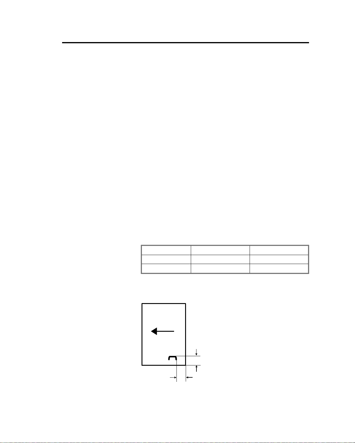
Staple Capacity: From 2 to 30 sheets (80 g/m2, 20 lb)
Staple Position:
a = 5 ± 2 mm (0.2" ± 0.08")
b = 5 ± 2 mm (0.2" ± 0.08")
a
b
1-1

10 July 1991
Staple Time: Within 2 seconds/staple
Staple Replenishment: Cartridge exchange (5,000 pieces/cartridge)
Power Source: AC 100 V (from copier)
Power Consumption: Average: less than 80 W
Maximum:
in sort/stack mode: less than 90 W
in staple mode: less than 170 W
Dimensions:
(W x D x H)
610 x 675 x 1035 mm
24.1" x 26.6" x 40.8"
Weight: Approximately 80 kg (177 lb)
1-2
2. COMPONENT LAYOUT
5
6
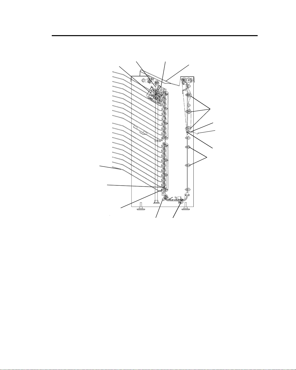
2.1 MECHANICAL COMPONENT LAYOUT
10 July 1991
11
10
12
13
14
1
2
3
4
9
8
1. Proof Tray
2. Vert ical Transport Rollers
3. Upper Entrance Guide
4. Lower Entrance Guide
5. Turn Gate
6. Diagonal Transport Rollers
7. 1st Horizontal Transport Roller
8. 2nd Horizontal Transport Roller
9. Distribution Rollers
10. Bin Gates
11. Bins
12. Grip Assembly
13. Jogger Plate
14. Stapler
1-3
7
3
5
10 July 1991
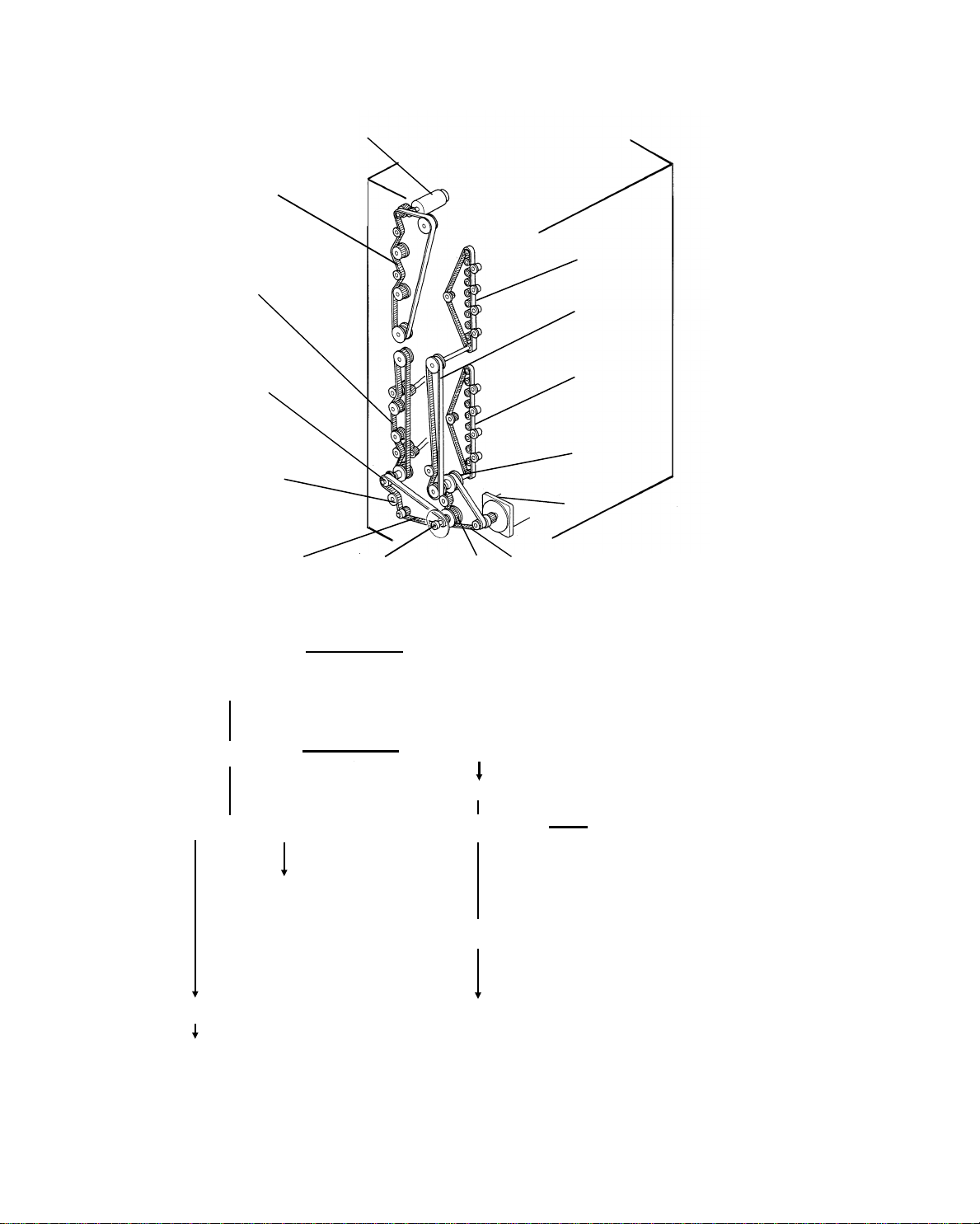
2.2 DRIVE LAYOUT
1
14
13
2
12
4
11
6
10
9
7
8
The drive train is as follows:
Proof Motor [1] Vertical Transport Rollers Drive Belt [14]
Main Motor [6]
Timing Belt [7] Timing Pulley [8]
2nd Horizontal Transport Roller [9]
Timing Pulley [5] Timing Belt [10] 1st Horizontal Transport
Roller [11]
11th∼20th Distribution
Rollers [4]
Timing Pulley [12]
Timing Belt [3] Diagonal Transport Rollers Drive Belt [13]
1st∼10th Distribution Rollers [2]
1-4
10 July 1991
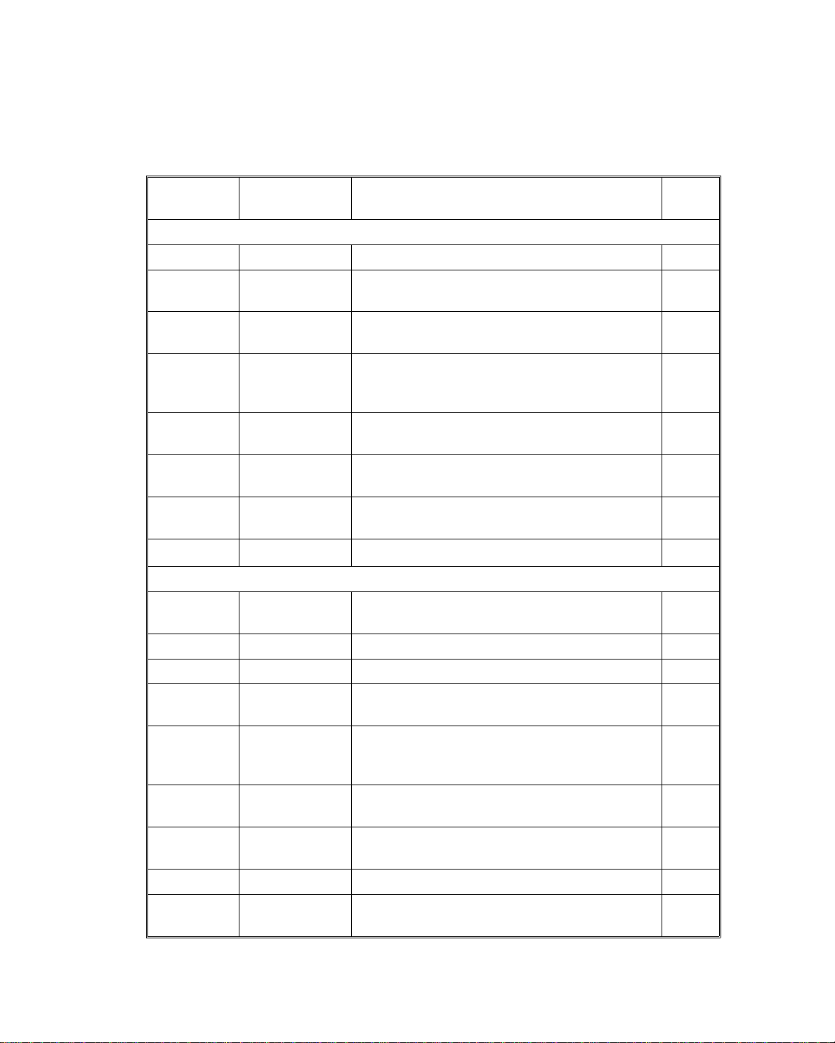
2.3 ELECTRICAL COMPONENT DESCRI P TI ON
Please refer to the Electrical Comp on ent La you t on the Reverse side of the
Point to Point (Water Pro of Paper) fo r symbol an d ind ex number.
SYMBOL NAME FUNCTION
Motors
M1 Proof Drives the vertical transport rollers. 1
M2 Staple Unit Drive
M3 Stapler
M4 Grip
M5
M6 Jogger
M7 Main
Sensors
Bin Side Plate
Drive
Drives the staple unit up and down to the
appropriate bin.
Feeds the staples and drives the stapler
hammer.
Drives the grippers forward and backward into
the bin to grip the copies and bring them to the
stapling position.
Drives the bin side plate. 16
Drives the jogger plate to jog the copies against
the bin side plate.
Drives the distribution, horizontal transport, and
diagonal transport rollers.
INDEX
NO.
5
9
11
20
21
S1 Exit
S2 Staple Unit H.P. Detects if the staple unit is in the home position. 6
S3 Grip H.P. Detects if the grippers are in the home position. 10
S4
S5 Bin Transport
S6
S7
S8 Jogger H.P. Detects if the jogger plate is in the home position. 22
S9 Timing
Staple Unit
Position
Bin Side Plate
Release
Bin Side Plate
H.P.
Detects paper jams at the sorter exit (Proof
Tray).
Detects the position of the staple unit. 12
Detects paper jams between the entrance guide
and the horizontal transport rollers in the
sort/stack or staple mode.
Detects if the bin side plate is in the released
position.
Detects if the bin side plate is in the home
position.
Provides pulses to the sorter stapler main
control board.
2
15
18
19
24
1-5
10 July 1991
SYMBOL NAME FUNCTION
Detects if there is paper jams at the distribution
S10 Bin/Jam (LED)
Sensors
S11
S12 Paper Detects whether copies are under the hammer. 14
S13 Staple H.P.
S14 Staple End Detects the staple end 7
Switches
SW1 Door Safety Controls the 100 V ac line. 4
SW2 Door Safety Controls the 24 V dc line. 3
Solenoids
Bin/Jam (Photo
Tr.)
section and detects if there is paper in the bins
(light emitting element).
Detects paper jams at the distribution section
and detects if there is paper in the bins (light
receiving element)
Detects if the staple hammer is in the home
position.
INDEX
NO.
30
17
8
SOL 1 Grip
SOL 2 ∼20
SOL 21 Turn Gate
Circuit Board
PCB 1 Main Control Controls all sorter stapler functions. 26
PCB 2 Bin Solenoid
PCB 3 Bin Solenoid
Capacitor
C Main Motor Motor start capacitor. 23
Bin
Opens and closes the grippers to grip copies on
the bins.
Opens and closes the bin gate to direct the
copies into the appropriate bin.
Opens and closes the turn gate to direct the
copies into either the proof tray or the bins.
Interfaces between the bin gate solenoids (sol 2
∼ 10) and the main control board.
Interfaces between the bin gate solenoids (sol
11 ∼ 20) and the main control board.
13
28
29
27
25
1-6
3. BASIC OPERATION
[B]
3.1 NORMAL MODE AND SORT/STACK MODE
[F]
[D]
[A]
[C]
10 July 1991
[E]
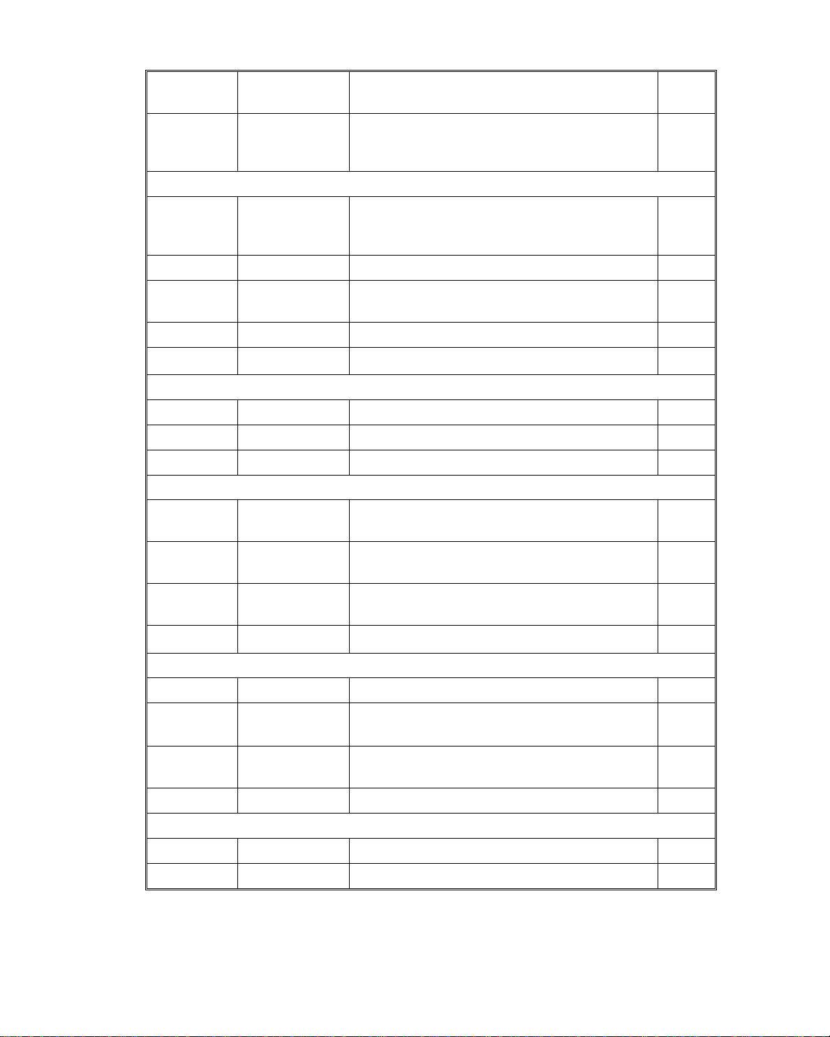
Copies exiting the copier pass thro ug h the entrance guide plates [A] to the
turn gate section. The turn gate [B] will send copies eith er to the proof tray or
to the bins, depending on the mod e.
- Normal mode - (from the turn gate section to the proo f tra y)
The turn gate solenoid [C] is energized and the turn gate turns clockwise
when the start key is pressed. The proo f mot or [D] ro ta te s the vertica l
transport rollers [E] and exit roller [F]. The turn ga te direct s copie s thro ug h
the vertical transport sect ion to th e proof tray.
In this mode, if a misfeed is detected in the sorter stapler, th e pro of moto r
stops and the turn gate sole no id turns off. The main moto r starts rotating.
Copies going through the copier are sent to the 1st bin through the diagonal
transport, horizo nt al transport, and distribu tio n section.
1-7
10 July 1991
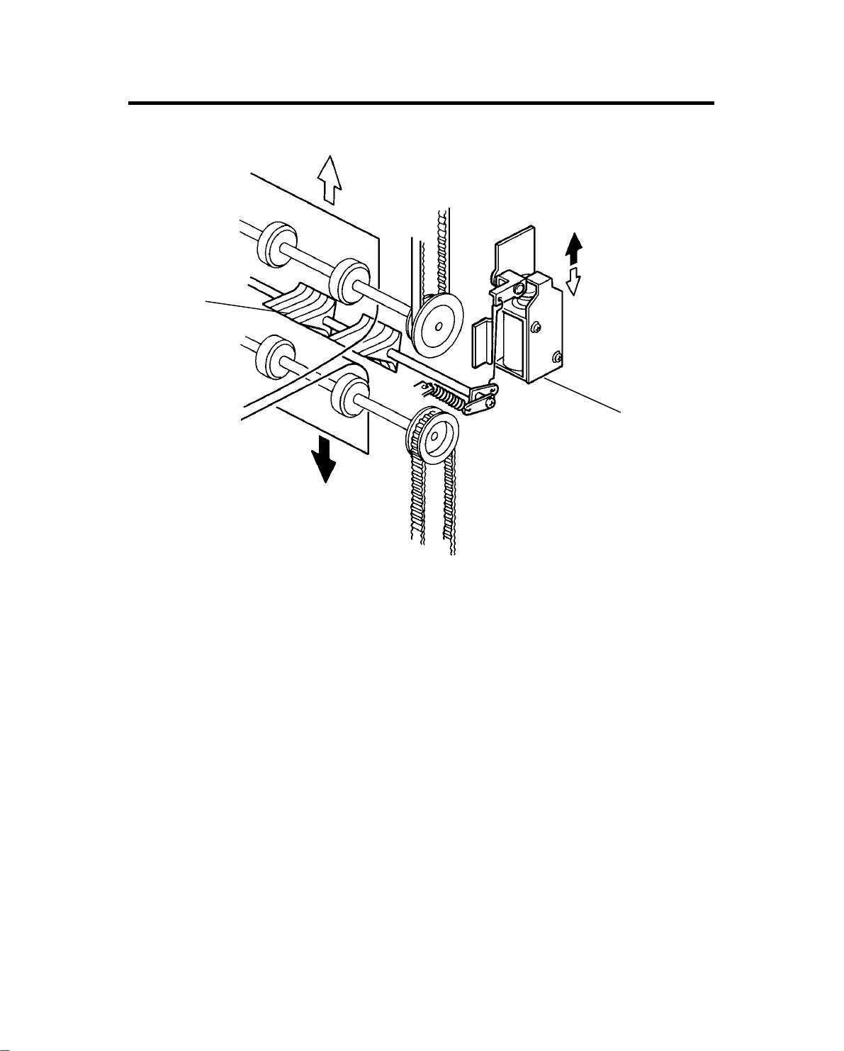
- Sort/Stack mode - (fro m t he turn gat e sect ion to th e bin s)
[H]
[G]
[B]
[F]
[A]
[D]
[C]
[E]
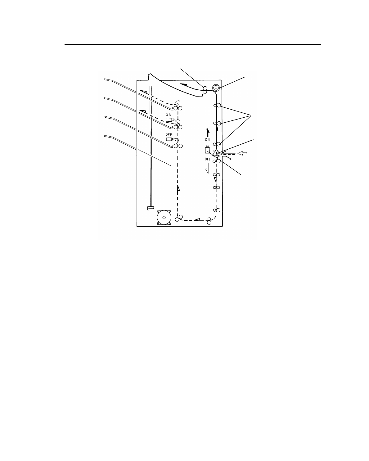
The turn gate solen oid [A] stays off and th e turn gate [B] also stays up when
the start key is pressed. The main motor [C] rotates the diagonal transport
rollers [D], horizontal transpo rt rolle rs [E] , and dist ribu tio n rolle rs [F].
The turn gate directs copies to the diagonal tran spo rt section. The diagonal
transport section fee ds cop ies dia go na lly. This is beca use copies are brought
to the front side in advan ce for easier jogging.
Copies are directed to the distrib ut ion section through the diagonal and
horizontal transp ort section. The appropriate bin ga te [G] opens and copies
are delivered to each bin.
The jogger plate [H] the n jog s to squ are the copies each time.
In this mode, if a misfeed is detected in the sorter stapler, the main mot or
stops. The proof motor sta rts rot at ing and the turn gate solenoid energizes.
Copies going throu gh the copier are directed to the proo f tray.
1-8
3.2 STAPLE MODE
10 July 1991
[A]
1
2
3
4
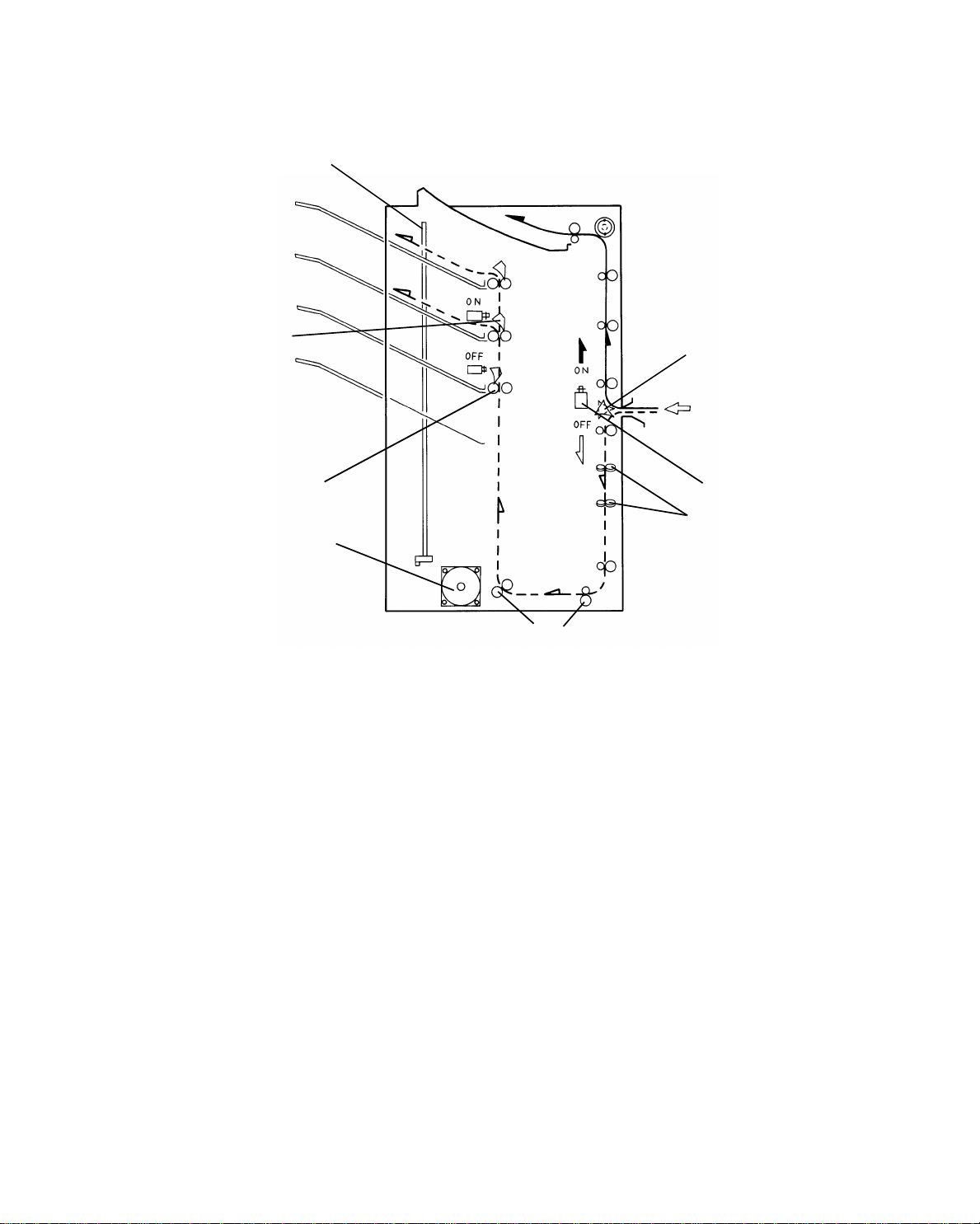
When the final set of copies is jog ged in the sort mode (figure 1), the stap le
unit staples the stacked copies as follows:
The grippers (A) move forward, and grip the copies (f igu re 2). The grip pers
bring the copies up underneath the stapler (f igu re 3). The stapler staples the
copies (figure 4). The copies are pushed back into th e bin . The grippers open
and return to the home posit ion. The staple unit moves to th e next bin (figure
5).
When the final set of copies is sta ple d, the stap le unit is ra ised to th e home
position.
5
There are two staple modes.
1) Automatic stapling:
In ADF mode, when the staple mode is select ed before pressin g the start
key, copies will be delivered to each bin and sta ple d auto mat ically.
2) Manual stapling:
In sort mode, after copies are sort ed in bins, the copies will be stapled
when the staple key is pressed. In sta ck mode, manual stapling is
impossible.
1-9

SECTION 2
SECTIONAL DESCRIPTION
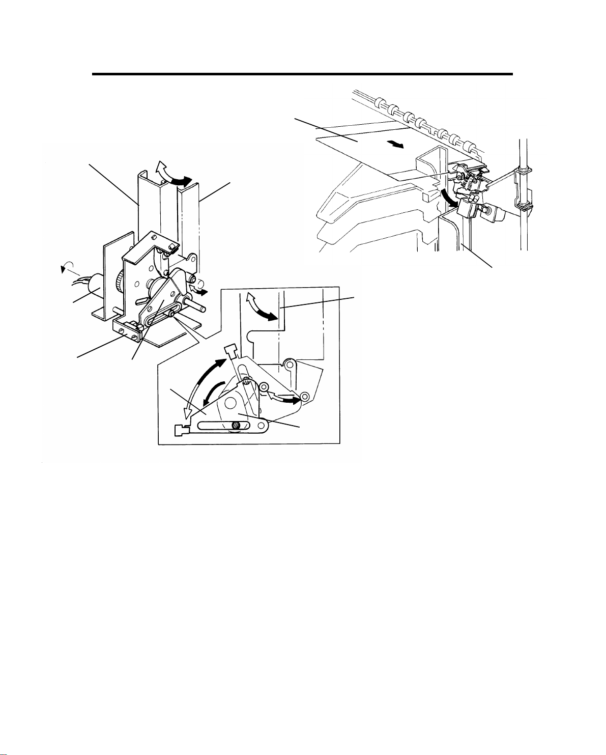
1. TURN GATE SECTION
[C]
[B]
10 July 1991
OFF
ON
[A]
[D]
The turn gate send s copies to the proof tray or th e bins depending on the
mode. In the normal mode , th e turn gate solenoid [A] turns on. The turn gate
[B], directs copies upward [C] th rough the vertical transport sect ion to the
proof tray.
In the sort, stack, or staple mode, the turn gate solenoid stays off. The tu rn
gate directs copies downward [D] to th e dia go nal t ran spo rt section.
2-1
10 July 1991
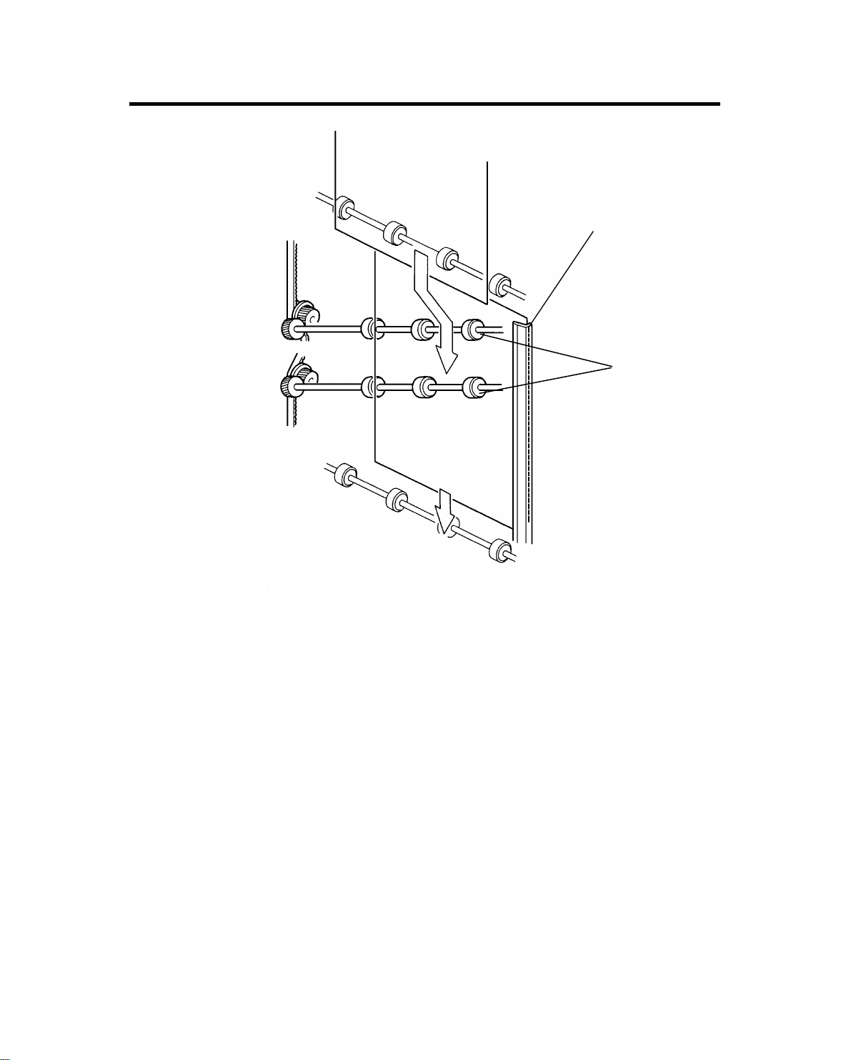
2. DIAGONAL TRANSPORT SECTION
[B]
[A]
In the sort, stack, or staple mode , th e dia gona l tran sport rollers [A] bring the
copies to the front side du ring transportation. Copies go to the horizont al
transport section alon g the diagonal transpo rt sto pp er [B].
2-2
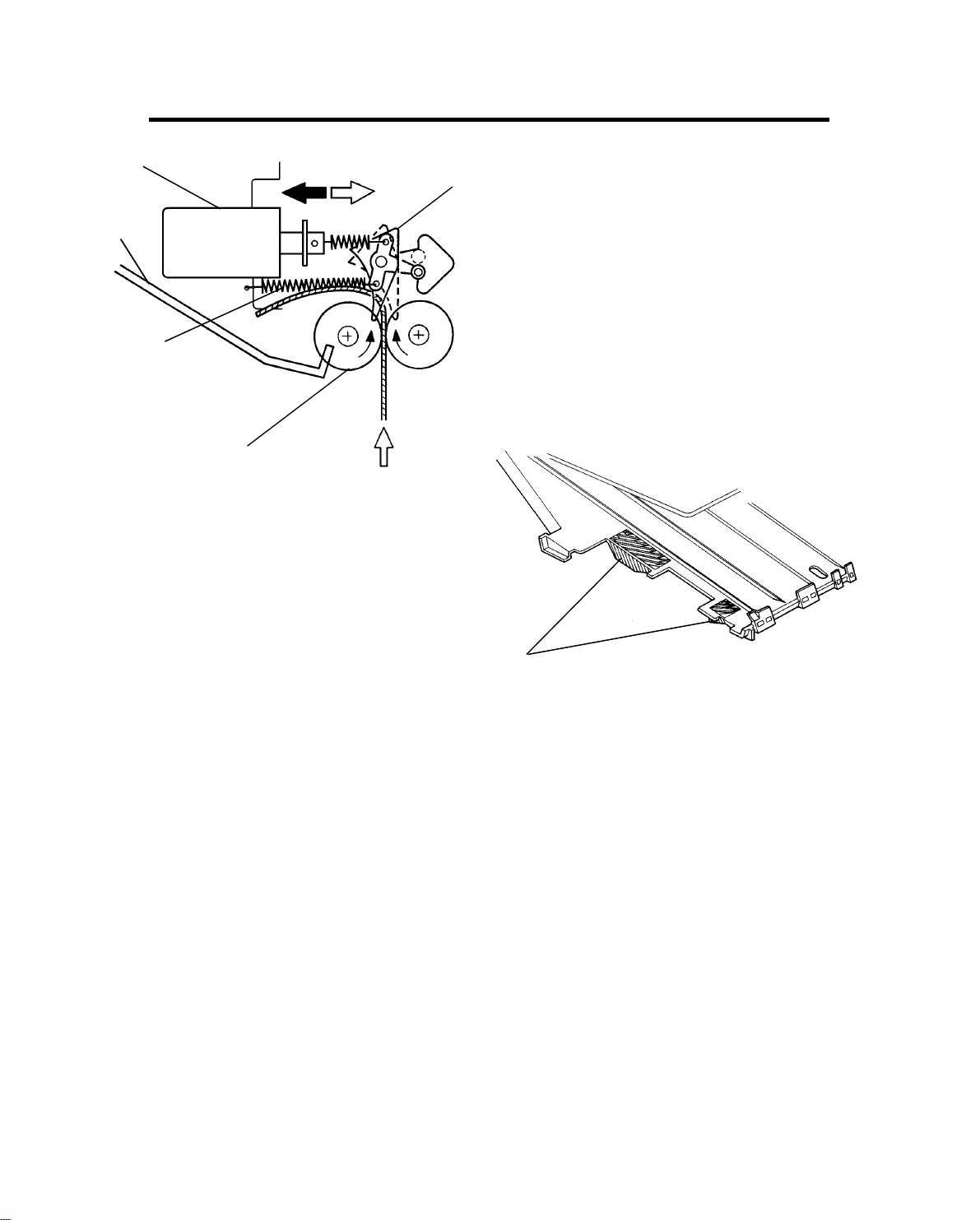
3. DISTRIBUTION SECTION
[B]
[E]
[C]
[A]
OFFON
10 July 1991
[D]
[F]
The distribution sect ion has the distribution rolle rs [ A] , 20 bin gates, and 19
bin gate solenoids (the 1st bin gate is always open).
When a bin gate solenoid [B] is of f, the return spring [C] holds the bin gate [D]
out of the paper path, allowin g the copies to pass to the upper bin.
The appropriate bin ga te solenoid turns on and open s the bin ga te . The other
solenoids are of f. Th e cop ies go to the bin [E] throug h th e ga te.
To prevent copies from curling an d so cau sing misstapling or wrong staple
positioning, th e bin has pa pe r flat teners [F] on the front side of th e bin .
2-3
C
10 July 1991
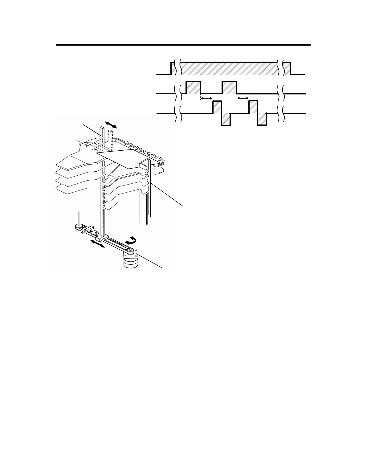
4. JOGGER SECTION
Copier
Main Motor
Jam Sensor
Jogger Motor
[B]
C
C: Depening on selected paper size.
[D]
[A]
When the start key is pressed in the sort, stack, or staple mode, the copier
sends the paper size informatio n to the sorte r stap ler un it. In acco rda nce with
this data, the jogger motor [A] drives th e jog ger plate [B] from the jogger
home position to where the width is 10 mm wider than the selected paper.
After the trailing edge of a copy passes th e jam sen sor (th e bin /ja m sensor),
and after the appropriate timing [C] for the select ed paper, the jogg er mot or
rotates and reverses. This makes the jogger plate push all the copies against
the bin side plate [D] to square the stack. Also, this makes the jogger plate
return to where the width is 10 mm wider than the selected pa pe r for the next
copy.
When the bin sensor in the bin/ja m sensor detects that all copies are
removed from the bins afte r jogg ing is fin ishe d, the jogg er pla te re tu rns to it s
home position.
2-4

10 July 1991
- Jogger off conditions -
1. Under the following conditions, the jogger plate does not jog after copies
are delivered to the bins.
• If paper is loaded in a bin by hand while the sort/sta ck, or
staple mode is selected.
• If the selected pape r size doe s not ma tch stap ling
specifications.
• If copies of different width are delivere d to the bins.
2. If paper is in a bin before the main switch is turned on, the sort /st ack
mode is disabled when th e sort er key is p resse d.
2-5
10 July 1991
5. BIN SIDE PLATE DRIVE SECTION
[F]
[A]
[E]
[E]
[B]
[G]
[E]
[D]
[D]
[C]
The bin side plate [A] is alwa ys in the home posit ion except during the staple
operation. The bin side plate takes part in the jogger f un ctio n (see jogger
section).
In the staple mode when all the copies have been jogged by the jogger plate,
the bin side plate drive motor [B] rotates the cam drive plate [C]. The pin on
the cam drive plate raises and lowers the actu at or cam [D], and the actuator
cam makes the bin side plate [E] move to the front side . Thus, the bin side
plate does not interf ere wit h th e copies [F] being brought to th e sta ple
position by the grip assembly.
When the staple operation for the final set of co pie s is completed, the bin
side plate drive motor rotates th e cam drive plat e until th e bin side pla te
home position sensor [ G] is act ua te d. This makes the bin side plate re tu rn to
the home position.
2-6
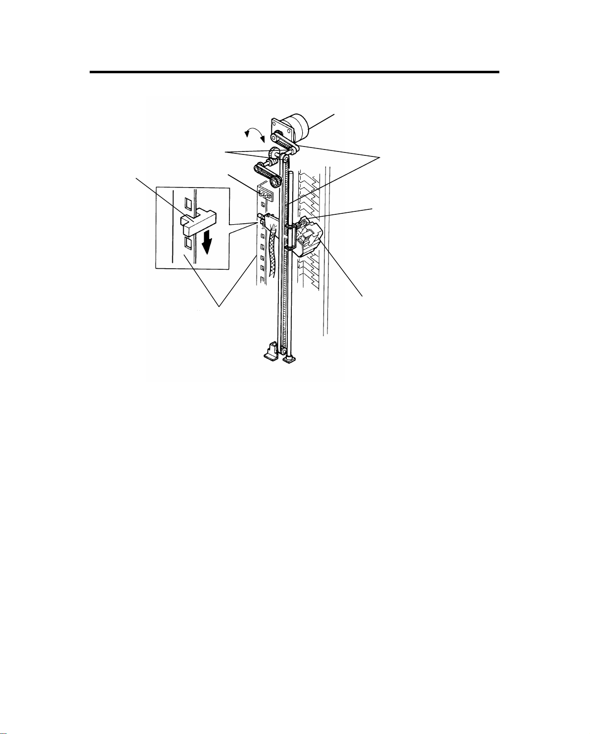
6. STAPLE UNIT
6.1 STAPLE UNIT DRIVE MECHANISM
10 July 1991
[C]
[D]
[F]
The staple unit consists of the grip assemb ly [A] and the stap ler [B ]. The
staple unit is lowered from the home position (the first bin ) to the 20th bin in
order to staple the copies in each bin. The grip assemb ly grips th e cop ies
stacked in the bin and positions them underneath the stapler. The stapler
staples the copies.
[H]
[G]
[E]
[A]
[B]
When the first set of copies is stapled, the staple unit drive mot or [C] drives
the staple unit downward via timing pulleys [D], and timin g belts[ E] . While the
staple unit is being lowered , th e sta ple unit posit ion sensor [F] tracks the
position actuator plate [G], generating an on/off signal that is sent to the
sorter stapler main control board. This way, the posit ion of the staple unit is
detected and the staple unit drive moto r st ops t he stap le un it whe n it rea ches
the next bin. When the la st set of cop ies in the bin is stapled, the stap le un it
drive motor reverses until the sta ple unit home posit ion sensor [H] is
actuated. At this time, th e sta ple unit is in the home po sitio n.
Because lifting the unit req uire s mo re torque than lowering it, the lifting spe ed
is about one third of the lowering speed.
2-7
[J]
[H]
10 July 1991
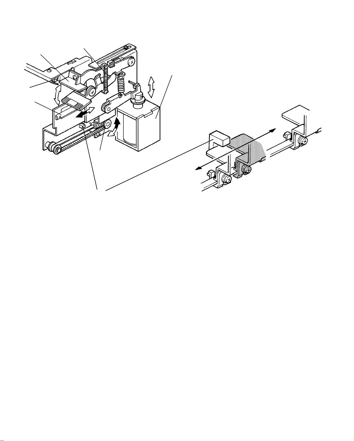
6.2 GRIP ASSEMBLY
[E]
[C]
[B]
[F]
[D]
[A]
[I]
[G]
When the bin side plate sta rts movin g to the front side, the grip mo to r [ A]
drives the grippers [B] into the bin. The grippers track the grip per guide [C].
The grip motor stops the grippers at the grip position. The grip solen oid [D] is
energized and it closes the grippers to grip cop ies in th e bin . Whe n th e bin
side plate reaches th e front side, the grip motor reve rses an d brings the
grippers with the copies to the staple position. The paper sensor [E ] checks if
copies are brought to the staple position correctly. Then, the copie s are
stapled, and the grip motor drives the grippers with the sta ple d copies ba ck
into the bin .
When the grip solenoid turns off, the return spring [F] opens the grippers. The
copies remain in the bin. Then , th e grippers return to the home posit ion for
the next cycle.
The grip home position senso r [G] is actuated while the grippers move from
the home position [H] to the grip position [I]. This sensor is deactuate d while
the grippers move from the home position to the staple position [J]. The
sorter stapler main control board sends the approp riat e pulses to the grip
motor (stepper motor) to determine the grip position and sta ple posit ion .
When the main switch is turned on, the grip motor turns forwa rd an d
backward to check wheth er th e grippers are in the home positio n. If no t, the
grip motor returns the grippers to their home posit ion .
2-8
[H]
[F]
10 July 1991
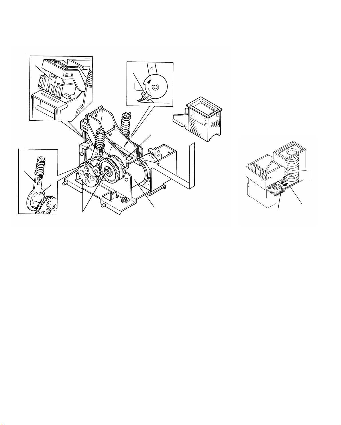
6.3 STAPLER
[C]
[G]
[B]
[E]
[A]
[D]
The stapler motor [A] drives the sta ple sheet drive belt [B].
The staple sheets are fed under th e hammer [C] .
The stapler motor drives th e sta ple hammer via gears [D], two eccentric ca ms
[E], and two links [F].
When the aligned copies are brought to the staple position by the grippers,
the stapler motor starts rot ating. When the cams complete one rotation, th e
staple home position sensor [G] is d eactuated. The stapler motor then stops.
When the paper sensor in the grip assembly does not detect that the copies
are under the hammer, th e sta pler motor does not rotate.
A paper sheet [H] with a notch cut-in is positioned at the bottom of the staple
cartridge. This paper sheet is fed out aft er th e last stap le she et . Whe n th e
leading edge of the not ch in the sheet is detecte d by the staple end senso r
[I], the sorter sta ple r unit recognizes the staple ne ar en d con dition. After the
job is completed, the Add Sta ple indicator lights on the cop ier operation panel
and the Start key turns to re d whe ne ver the staple mode is selected.
[I]
2-9

10 July 1991
- Staple prohibit conditions -
1. Under the following conditions, the staple mode is prohibited when the
staple key on the operation panel is pressed.
• If paper is in a bin before the main switch is turned on.
• If the selected pape r size doe s not ma tch stap ling
specifications.
2. Under the following conditions, the staple mode is canceled.
• If paper is loaded in a bin by hand while the staple mode is
selected.
• If only one sheet is delivered to th e bin.
• If the number of sheets stapled excee ds the staple capacity.
3. Under the following conditions, the manu al sta plin g mode in sort mode is
prohibited.
• If paper is loaded in a bin by hand while the sort mode is
selected.
• If the paper size in the bin does not match sta plin g
specifications.
• If only one sheet is delivered to th e bin.
• If copies of different width are de livere d to the bin.
• If copies already stapled are left in the bin.
2-10
7. JAM DETECTION AND STAPLE ERROR
Copier Exit Sensor
J1
(1,300m sec)
J2
Sorter Exit Sensor
Bin transport
Sensor
Jam Sensor
360pls
J3
*This is jam checking timing for the 1st bin. Timing
depends on the bins.
(1,900m sec)
ON Check
220pls
J4
436pls*
436pls*
1 pulse ≈ 5.13 ms
J5
10 July 1991
J6
7.1 SORTER JAMS
The sorter stapler main control board detects jams when the following
conditions are detect ed . In these cases, a jam signal is sent to th e copier, the
copier stops the paper feed and indicates a sorter misfeed.
- Normal mode -
J1: The sorter exit sensor ha s not turned on for 1,300 ms after t he copie r exit
sensor turns off (paper check).
J2: The sorter exit sensor sta ys on fo r 1,9 00 ms or more (no pape r check).
- In sort/stack or staple mode -
J3: The bin transport senso r h as no t tu rned on for 360 pulses after the copier
exit sensor turns on (paper check).
J4: The bin transport senso r st ays on for 22 0 pu lses (no pap er check).
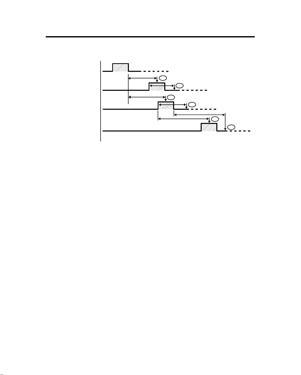
J5: The jam sensor has not tu rned on for the appropria te numb er of pulses
after the bin transport sen sor tu rns on (pap er che ck). This nu mbe r
depends on the bin. (See the diagram in the next page.)
J6: The jam sensor has not turne d of f afte r t he app rop riat e number of pulses
after the bin transport sen sor tu rns of f (no pap er che ck). This nu mbe r
depends on the bin. (See the diagram in the next page.)
2-11
10 July 1991
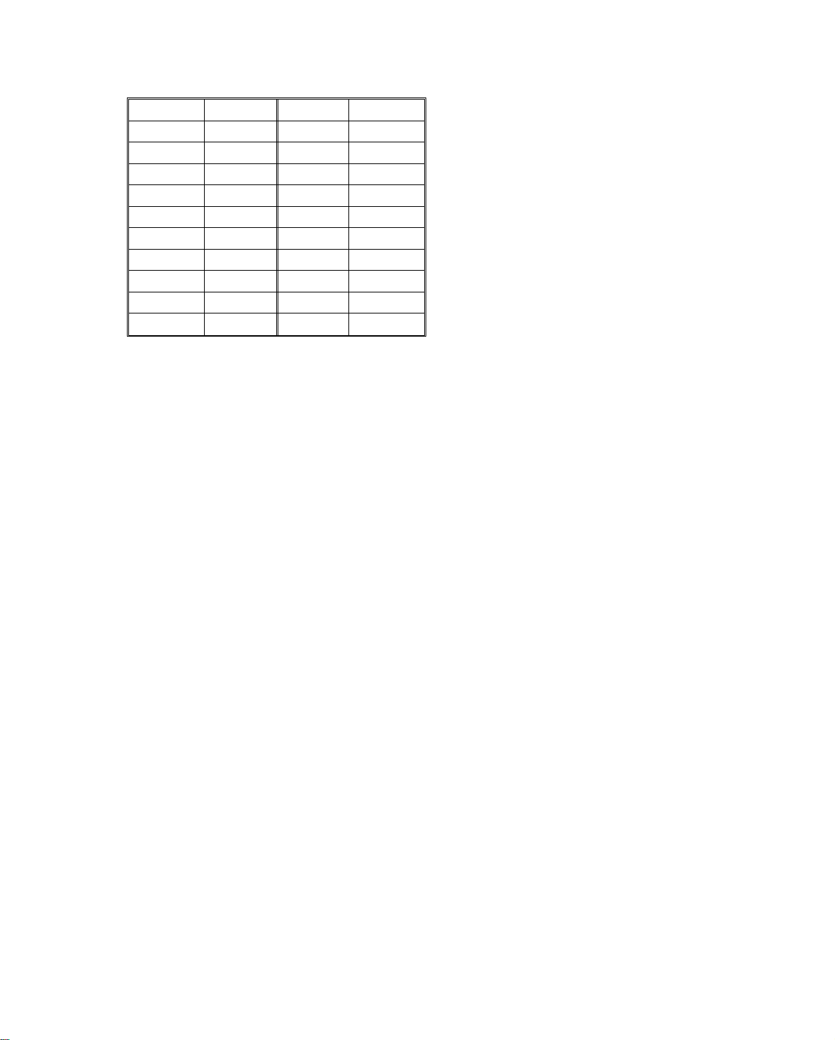
- Jam checking timing diagram -
Bin no. Pulses Bin no. Pulses
1 436 11 294
2 422 12 280
3 408 13 266
4 394 14 252
5 382 15 240
6 368 16 226
7 354 17 214
8 342 18 200
9 328 19 186
10 314 20 174
7.2 STAPLE ERROR
The sorter stapler main control board detects a staple error when the
following conditions are detected.
Error 1 The paper sensor in the grip assembly turns on (paper is still in
the grip assembly) while the staple unit is being lowere d.
In this case, a staple error sign al is sent to the copier. The copier
cancels the staple mode and indicates a staple error.
After paper left in th e grip pe rs is remo ved , the staple unit returns
to the home position. Whe n the staple key is pressed, th e stapler
begins to staple the rest of the copie s st art ing from th e bin
following the bin where the jam happened.
Error 2 The paper sensor in the grip assembly does not turn on (paper is
not in the grip assembly) when the grippers are in the staple
position.
In this case, the staple unit skip s stap ling this bin and moves to
the next bin for staplin g.
2-12

Home
c
ON
10 July 199
1
8. TIMING CHART
0145678910111213141516172627
Timing Chart 1 (Normal mode: B5 sideways 5 copies)
Copier main
I/F Receive from copier
I/F Send to copier
Proof Motor
Turn Gate Solenoid
Exit Sensor
motor on signal
OFF
OFF
ON
ON
500msec
Timing Chart 2 (Sort & Staple mode: B5 si deway s 2 originals x 5 copies)
Copier mainl
I/F Receive from copier
I/F Send to copier
Main Motor
Bin Transport Sensor
2nd Bin Solenoid
3rd Bin Solenoid
4th Bin Solenoid
5th Bin Solenoid
Jam Sensor
Jogger Motor
Staple Unit Operation
Forward
Reverse
*A (Staple Unit Operation)
Bin Side Plate Drive Moto r
Bin Side Plate H.P. Sensor
Bin Side Plate Release Sens o r
Grip Motor
Grip Solenoid
Stapler Motor
Staple H.P. Sensor
Staple Unit Drive Motor
Staple Unit H.P. Sensor
Staple Unit Position Sensor
Forward
Reverse
Home
Down
Up
motor on signal
ON
OFF
OFF
16 17 18 19 20 21 22 23 24 25 26
ON
Released
OFF
ON
OFF
OFF
ON
150msec
250msec
262pls
250msec
OFF
Home
(OFF)
(ON)
1 staple cycle
Sorter exit signal
ON
248pls
OFF
OFF
300msec
Sorter exit signal
ON
234pls
ON
OFF
222pls
OFF
Copier main
motor off signal
ON
Solenoid on timing
Bin No.12345678910
Pulses — 262 248 234 222 208 194 182 168 154
Bin No. 11 12 13 14 15 16 17 18 19 20
Pulses 134 120 106 92 80 66 54 40 26 14
Jogger start timing
Paper Size A3 B4 A 4S A4L B5S B5L DLT LG LTS LTL
Timing [msec] 640 530 300 395 300 315 665 510 300 360
S: Sideways L: Lengthways
Copier main motor off signal
Stapling on signal
*A
[sec]
[se
2-13

SECTION 3
INSTALLATION

10 July 1991
1. ACCESSORY CHECK
Check the quantity and cond itio n of the accessories in the box according to
the following list:
1. Front Connecting Bracket ......................................................1
2. Rear Connecting Bracket ......... ............ .. ............ ............ .. .....1
3. Locking Bracket .....................................................................2
4. Fixing Bracket ........................................................................1
5. Upper Entrance Guide Mylar .................................................1
6. Lower Entrance Guide Mylar .................................................2
7. Sorter Stapler Key She et .............. .......... .......... .. .......... .........1
8. Staple Position Decal ...........................................................1
9. Staple Cartridge .....................................................................1
10. Stepped Screw ......................................................................2
11. Grounding Screw with Toot he d Wash er.... .............................1
12. Philips Pan Head Screw-M4 x 8 ............................................6
13. Caster Stopper .......................... ............................................ 2
14. Operating Instructions
Number of Languages: (-15, -17 machines).. .. ...................1
(-16 machine)...............................2
(-25, -26 machines)......................5
15. New Equipment Condition Report
(-17, -27 machines only).........................................................1
16. Envelope for N.E.C.R.
(-17 machine only) .................................................................1
17. Installation Procedure ...........................................................1

[F]
10 July 1991
2. INSTALLATION PROCEDURE
[D]
[B]
[A]
[C]
[E]
[B]
CAUTION: Unplug the copier power cord before star ting the foll owi ng
procedure.
1. Remove the strip of tape [A] on the front door.
2. Open the front door, th en remove 5 strips of tape [B] and a styrofo am
block [C]. Raise the staple unit by rotating the staple unit positionin g kno b
[D] counterclockwise, the n remo ve th e sponge cushion [E] underneath.
3. Remove the copier upper rear cover (2 screws) and the sorter stapler
rear cover (remove 3 screws, loosen 1 screw).
4. Remove 3 plastic caps [F] from the copier up per le ft cover.

[A]
10 July 1991
[C]
[D]
[B]
[C]
[E]
5. Install the front and re ar con ne cting brackets [A], [B] on the copie r a s
shown (2 screws each).
6. Stick the upper entrance guide myla r [C] on the copier upper left cover
and stick the two lower entrance gu ide mylars [ D] on the exit cove r as
shown.
7. For now, install the fixing bracket [E ] on the sorter stapler at the lowest
position (2 screws). (See step 11)

10 July 1991
[B]
[A]
[C]
8. Pass the harnesses [A] th rou gh the access hole an d connect the sorter
stapler with the copier. Make su re th at the stud on the front conn ect ing
bracket [B] is positioned in the sorter stapler positioning hole.
NOTE: Be careful not to damage the harnesses and the entrance guide
mylars when connecting the sorter stapler with the copier.
9. Secure the grounding wire [C] under the optics control board (1 grounding
screw with toothed wash er), and coup le the 3 connectors as follows:
Sorter Stapler Connecto r Copier Connector
2p (Red) 2p (Red)
4p (White) 4p (White)
2p (Fiber Optic Cable) CN114 on the main board

[A]
[A]
10 July 1991
[C]
[B]
10. Install the locking brackets [A] at the front and the re ar to secure the
sorter stapler to the copier (1 stepped screw each).
11. Loosen the 2 screws, lift the fixing bracket [B] up against the copier base
plate and retighten the screws.
[D]
12. Remove the finisher key sheet [C] an d stick th e sorter stapler key sheet
[D] on the operation panel.

[C]
10 July 1991
[A]
[B]
[C]
13. Stick the staple position deca l [A] on the ARDF as sho wn. (If there is n o
ARDF, stick it on the corresponding position of the platen cover. )
14. Remove the green plastic clip [B ] fro m the staple cartridge, and install the
cartridge in the stapler.
15. Reinstall the covers.
16. Turn on the main switch of the copier and test the operation of the sorte r
stapler.
NOTE: * The copier recognizes automatically that th e sorter stapler is
installed, so it is unnecessary to set the SP #71.
* The stapler will not be stapling for the first 10 or so copies until
the first staple comes to th e pro pe r position from the cartridge.
17. If at the top the gap bet ween the sorter stapler a nd the copier is too great,
adjust the gap by placing ca ste r st oppe rs [ C].

SECTION 4
SERVICE TABLES

10 July 1991
1. SERVICE TABLES (MAIN CONTROL BOARD)
1.1 DIP SWITCHES
DIP SW 100 0 : OFF 1 : ON
1234 5 6 Function Remarks
0 0 0 0 0 Proof Motor Speed Adjustment #1
1 0 0 0 0 Sorter Free Run #2
0 1 0 0 0 Staple Unit Free Run #3
*
1 1 0 0 0 Sorter & Staple Unit Free Run #4
1
0 0 1 0 0 Lowers Staple Unit (To 6th Bin)
1 0 1 0 0 Lowers Staple Unit (To 20th Bin)
0 1 1 0 0 Releases Bin Side Plate
0 0 0 0 0 1 Bin/Jam Sensor Adjustment
0 0 0 0 0 0 Initial Normal Setting
NOTE: *1 Confirm the setting from DIP SW100-2 to -6 before turn ing on
DIP SW100-1 (Start SW function).
Turn off DIP SW100-1 to st op the fun ction.
Remarks
#1: The proof motor a nd turn gate solenoid turn on.
#2: The main motor turn s on. Th e bin solenoids turn on in order and th e
jogger motor drives the jogger pla te (B5 lengthwise size) as each bin
solenoid turns on.
#3: The staple unit (grip asse mbly and stapler) movement is repeate d fro m
the 1st to 20th bins. When there is no paper in a bin, staplin g op era tion is
skipped for that bin.
#4: #2 and #3 are repeated together.
Combinations oth er than those above are used only a t th e factory.
4-1

10 July 1991
1.2 LED AND VARIABLE RESISTORS
LED NO. VR NO. FUNCTION
100 100 Adjusts jam sensor sensitivity.
101 101 Adjusts bin sensor sensitivity.
102 102 Adjusts proof motor speed.
1.3 TEST POINTS
NUMBER FUNCTION
TP 100 GND
TP 101 + 5 V
TP 102 + 24 V
4-2

10 July 1991
2. PREVENTIVE MAINTENANCE SCHEDULE
2.1 PM TABLE
C: Clean L: Lubricate
EM 320K NOTE
Transport, Distribution, and Exit Rollers C Da mp clot h
Bins C Damp cloth
Bin/Jam, Paper Sensors C Blower brush
Launa oil or equivalent;
Bushings L
Gears L
Worm gears L
Diagonal Transport Rollers C Damp cloth
Diagonal Transport Stoppe r C Alcohol
Staple Unit Guide Rod, Pa d L Launa oil
if bushings generate
noise.
Grease-501;
if gears generate noise.
Heat Resisting Grease
MT-78;
if worm gears generate
noise.
2.2 REGULAR PM EXPLANATIO N
The diagonal transport rolle rs a nd/o r t he diag on al tra nsport stopper become
dirty because of paper dust an d to ne r adh ering to them. This causes copies
to transport incorrectly, skew, an d jam. Clean ing them is required at regular
intervals.
If the diagonal transport stopper mylar is deformed or damaged, cop ies
transport incorrectly, skew, and jam. In this case , replace the mylar.
4-3

SECTION 5
REPLACEMENT
AND
ADJUSTMENT

10 July 1991
1. STAPLER REMOVAL AND REINSTALLATION
[B]
[A]
1. Open the front cover.
[C]
2. Push up the stapler relea se lever [A] and remove the stapler [B].
3. Reinstall the stapler.
NOTE: 1. The connector shut ter release plate [C] sho uld be inse rted as
shown.
2. Make sure that the sta ple r re lea se lever is lowered to the
original position after th e sta ple r is correc tly set .
5-1

[D]
10 July 1991
2. GRIP ASSEMBLY REMOVAL AND GRIP
SOLENOID ADJUSTMENT
2.1 GRIP ASSEMBLY RE MOV A L
[E]
[C]
[B]
[A]
[F]
[G]
[H]
[I]
1. Open the front cover [A].
2. Remove the proof tray [B] (5 screws) and fron t cove r [ C] (4 screws).
3. Move the grip assembly [D] betwe en the 1st bin and 7th bin by tu rnin g the
knob [E].
4. Remove the stapler [F] by pressing up the stapler release lever [G].
5. Remove the frame connector cover [ H] (2 screws).
6. Disconnect the 3 connectors [I ] an d remove the staple harness [J] (2
screws) from the frame connector cover.
5-2
[J]

[B]
10 July 1991
[D]
[C]
[A]
[E]
7. Remove the harness cover [A] (2 screws).
8. While holding the grip assembly [B], remove the timing belt clamp [C] (2
screws). Gently lower the grip assembly to the bottom.
9. Remove the fixing plate [D] (1 screw).
10. While holding the grip assemb ly, pu ll out the staple un it gu ide rod [E] from
the grip assembly.
5-3

10 July 1991
2.2 GRIP SOLENOID ADJUSTME NT
[B]
[A]
(C)
Adjustment standard: 2.5 ± 0.5 mm
1. Remove the grip assembly (see the grip assembly removal).
2. Adjust the gripper solenoid stroke (2 screws).
When the solenoid plunger [ A] is pressed so tha t th e grip pe r arms [ B]
touch each other, the gap (C) should be 2.5 ± 0.5 mm.
5-4

10 July 1991
3. DIAGONAL TRANSPORT STOPPER MYLAR
REPLACEMENT
[B]
[A]
1. Open the front doo r .
2. Release the transport plate.
3. Remove the diagonal transport stopper [A] (3 screws).
4. Slide out the mylar [B] from the diagonal tran sport stopper as shown.
5-5

[G]
[C]
10 July 1991
4. JOGGER PLATE REMOVAL AND
REINSTALLATION
4.1 JOGGER PLATE REMOVAL
[A]
[F]
[D]
[B]
1. Remove the proof tray [A] (5 screws) and the bot tom cover [B ] (2 screws).
2. Push the upper part of the jogger plate [C] to the left and hold it.
3. After that, pull the jogger plate up and hold it.
4. Swing the jogger plate out of th e bo ttom holder [D], and gently let the
jogger plate fall out of the upp er ho lde r [ F].
5. Pull the jogger plate out through the stay ho le [G].
5-6

4.2 JOGGER PLATE REINS TALLATI ON
[C]
[C] [B]
[E]
10 July 1991
[E]
[A]
[D]
1. Insert the jogger plate [A] through the stay ho le [B].
2. Insert the jogger plate into the ho le of the upper holder [ C] as shown and
hold it.
3. Position the jogger plate at the lower holder [D].
NOTE: The pressure springs [E] sho uld be placed as shown.
5-7

10 July 1991
5. BIN REMOVAL
[C]
[A]
Good
No good
[B]
1. Remove the front and rear covers (4 screws each).
2. Remove the jogger plate (see jog ger p lat e remo val).
3. Turn on the main switch.
4. Turn on DIP SW100-3, -4 and -1 [A]. Make sure you turn on the switch es
in that order.
5. When the bin side plate [B]is rele ased, turn off the main switch .
6. Pull out the sorting bins [C].
NOTE: 1. The 10th and 20th bins do not have an antista tic bru sh.
2. When reinstalling th e bin s be sure tha t the bins are positioned
correctly as shown.
3. After reinstalling the bins, turn off DIP SW100-1, -3 and -4.
5-8

6. TRANSPORT PLATE REMOVAL
[A]
[E]
[C]
[D]
10 July 1991
[B]
[F]
6.1 VERTICAL TRANSPORT PLATE REMO VAL
1. Remove the rear cover (4 screws).
2. Remove the turn gate lever [A] (1 screw).
3. Open the front door [B].
4. Remove the snap ring [C], th en lift an d remove the vertical the transport
plate [D].
6.2 DIAGONAL TRANSPORT PLATE REMO VAL
1. Open the front cover [B].
2. Remove the snap ring [E], then lift and remove the diagonal transport
plate [F].
5-9

10 July 1991
6.3 DISTRIBUTION TRANSPO RT PLATE REMO VAL
[B]
[C]
1. Open the front cover [A].
2. Remove the snap ring [B].
3. Lift and remove the dist ribution transport plate [C].
[A]
5-10

10 July 1991
7. VERTICAL TRANSPORT UNIT REMOVAL
[A]
[C]
[B]
1. Remove the proof tray (5 screws) and the rear cover (4 screws).
2. Disconnect the proof motor/exit sensor connector [A] and the turn gate
solenoid connector [B].
3. Remove the vertical transport un it [C] (6 screws, an d 1 screw fo r t he
harness clamp).
5-11

10 July 1991
8. DIAGONAL TRANSPORT UNIT REMOVAL
[A]
[C]
[B]
1. Remove the rear cover (4 screws).
2. Loosen the timing belt [A].
3. Remove the support bracket [B] (2 screws) an d th e timin g be lt .
4. Remove the diagonal transport unit [C] (7 screws).
5-12

9. BELT TENSION ADJUSTMENT
[A]
[B]
[D]
[C]
[E]
[F]
10 July 1991
[G]
aa
a: Bending (mm)
[H]
[B]
1. Remove the respective covers for the following belt tension adjustment:
Timing Belt [A] .......... .. ........ Proof Tray
Timing Belt [B] .......... .. ........ Proof Tray
Bottom Cover
Timing Belt [D] .................... Rear Cover
Timing Belt [G] .......... .......... Rear Cove r
Timing Belt [C] .................... Rear Cover
Timing Belt [C] .................... Rear Cover
Timing Belt [E] .......... .......... Rear Cover
Timing Belt [H] .................... Rear Cover
Timing Belt [G] .......... .......... Rear Cove r
2. Adjust the timing belt te nsio n as follows:
Timing Belt Bending Pressure
A 4 mm
B 5 mm
C 5 mm
D 8 mm
E 8 mm
F 6 mm
G 5 mm
H 6 mm
5-13
200±50 g
50±20 g
140±40 g
100±50 g
100±50 g
100±50 g
200±50 g
100±50 g

[B]
10 July 1991
10.MAIN CONTROL BOARD REPLACEMENT
AND ADJUSTMENT
10.1 MAIN CONTROL BOARD REPLACEMENT
[B]
[D]
[B]
[A]
1. Remove the rear cover [A] (4 screws).
2. Disconnect the main control board connectors [B] and fiber cable [C].
NOTE: When disconnecting the fibe r ca ble , do not pull it by th e cable,
but by the connector.
3. Replace the main control board [D] and con nect th e con ne cto rs.
4. Turn on the main switch.
5. Adjust the proof moto r sp eed an d bin/jam sensors (see next two pages).
6. Turn off the main switch.
[C]
5-14

10.2 PROOF MOTOR SPE ED ADJ USTME N T
10 July 1991
1. Turn on DIP SW100-1 [A].
[C]
[B]
[A]
2. If LED102 [B] is on, turn VR102 [C] coun te rclockwise unt il LED1 02 turn s
off.
3. Turn VR102 clockwise until LED102 starts blinking and go on turning until
it is continuously on.
4. Turn off DIP SW100-1.
5-15

10 July 1991
10.3 BIN/JAM SENS OR ADJ USTME N T
[A]
[B]
[C]
[D]
[E]
1. Turn on DIP SW 100-6 [A].
2. If LED100 [B] and LED101 [C] are on, turn VR100 [D] and VR101 [E]
clockwise until LED100 and LED101 turn off.
3. Turn VR100 and VR101 counterclockwise until LE D100 and LED101
start blinking and go on turning until they are continuou sly on.
4. Turn off DIP SW 100-6.
5-16

11.MAIN MOTOR REPLACEMENT
[B]
10 July 1991
[A]
[L]
[K]
[G]
[J]
[I]
1. Remove the rear cover [A] (4 screws).
2. Remove the timing pulleys [B, C] (1 Allen screw each) and timing belt [D].
[O]
[F]
[M]
[N]
[H]
[E]
[D
[C]
3. Remove the support bracket [E] (4 screws, and 2 screws for th e ha rne ss
clamps).
4. Remove the timing sensor bracket [F] (1screw).
5. Loosen the timing belt and remove the timing belts [G, H].
6. Remove the disk [I] and the timing pulley [J] (1 Alle n screw ea ch).
7. Remove the capacitor [K] (1 screw) and disconnect the motor harness [L].
8. Remove the grounding wire [M] (1 screw) the main motor assembly (4
stepped screws).
9. Remove the timing pulley [N] (1 Allen screw) and rep lace the main motor
[O] (3 screws).
NOTE: The timing pulley is used for both the 50 Hz and 60 Hz machines.
50 Hz = 18T 60 Hz = 14T
5-17

SECTION 6
TROUBLESHOOTING

10 July 1991
1. SERVICE CALL CONDITIONS
1.1 CODE # A1 – PROOF MOTOR ERROR
- Definition -
When the proof motor is turning, the encoder pulse takes over 250 msec to
change.
- Possible Causes -
• The proof motor is defective
• The main control board is defective
- Action -
Turn the main switch off and on.
Does the proof motor turn wh en the main switch is turne d on?
Yes No
Check the continuity between CN140 and CN400 through CN405.
Good No good
Repair the harness.
Replace the proof moto r.
Replace the main control board or the proo f mot or.
6-1

10 July 1991
1.2 CODE # A2 – TIMI NG SENSOR OUTPUT ERROR
- Definition -
When the main motor is turning , the timin g sen sor ou tp ut take s over 100
msec to change.
- Possible Causes -
• The timing sensor is defective
• The main motor is defective
• The main control board is defective
- Action -
Turn the main switch off and on.
Does the main motor turn when the main switch is turne d on?
Yes No
Check the voltage between CN300-1 and CN300-2.
100 V 0 V
Check the copier
Check the continuity betwe en CN310 -1 an d CN31 0-2 .
Good No good
Replace the door safety switch (AC).
Check the continuity betwe en CN330 -1 an d CN33 0-2 .
Good No good
Replace the main motor.
Check the continuity between CN300 and CN120 through CN310
and CN330.
Good No good
Repair the harness.
Replace the main control board .
6-2

Check the timing sensor. (between CN180-7 and the ground)
Good No good
≤ 1.0 V > 1.0 V
≥ 4.0 V < 4.0 V
Check the continuity between CN180 and CN450.
Good No Good
Repair the harness.
Replace the timing sensor.
Replace the main control board .
10 July 1991
6-3

10 July 1991
1.3 CODE # A3 – JOGGER H.P. SENSOR OUTPUT ERROR
- Definition -
• When the jogger plate moves forward, the home position sensor takes
over 150 msec to turn off.
• When the jogger plate moves backward , th e ho me position sensor
takes over 1 sec to turn on.
- Possible Causes -
• The jogger H.P. sensor is defective
• The jogger motor is defective
• The main control board is defective
• The timing belt is not fixed
- Action -
Turn the main switch off and on.
Does the jogger plat e move when the main switch turned on?
Yes No
Does the jogger motor turn?
Yes No
Check the continuity between CN170 and CN470.
Good No go od
Repair the harness.
Check the continuity of the jo gger motor.
Good No good
Replace the jogger motor.
Replace the main control board .
Attach the holder to the belt.
6-4

Check the jogger H.P. sensor. (between CN190-1 and the ground)
Good No good
≥ 4.0 V < 4.0 V
≤ 1.0 V > 1.0 V
Check the continuity between CN190 and CN475.
Good No good
Repair the harness.
Replace the jogger H.P. sensor.
Replace the main control board .
10 July 1991
6-5

10 July 1991
1.4 CODE # A4 – STAPLE UNI T POSITION ERROR
- Definition -
When the staple unit lowers t o th e ne xt bin , the staple unit position sensor
stays on for more than 1 sec or stays off for more than 50 0 msec.
- Possible Causes -
• The staple unit H.P. sensor is defective
• The staple unit position sensor is defective
• The staple unit drive motor is defective
• The main control board is defective
- Action -
Turn the main switch off and on.
Does the staple unit drive motor tu rn whe n th e main switch is turned on?
Yes No
Check the continuity between CN150 and CN485.
Good No good
Repair the harness.
Check the continuity of the st aple un it drive motor.
Good No good
Replace the staple unit drive moto r.
Replace the main control board .
Check the staple unit H.P. Sensor. (between CN18 5-9 and the ground)
Good No good
≥ 4.0 V < 4. 0 V
≤ 1.0 V > 1. 0 V
Check the continuity between CN185 and CN480.
Good No good
6-6

10 July 1991
Good No good
Repair the harness.
Replace the staple unit H.P. sensor.
Check the staple unit position sensor. (between CN185-10 and the ground)
Good No good
≥ 4.0 V < 4. 0 V
≤ 1.0 V > 1.0 V
Check the continuity between CN185 and CN570 through CN560.
Good No good
Repair the harness.
Replace the staple unit position sensor.
Replace the main control board .
6-7

10 July 1991
1.5 CODE # A5 – GRIP MOTOR ERROR
- Definition -
When the grip motor moves forward or ba ckward , th e grip H.P. sensor output
takes over 250 msec to change .
- Possible Causes -
• The grip H.P. sensor is defective
• The grip motor is defective
• The timing belt is not fixed
• The main control board is defective
- Action -
Turn the main switch off and on.
Does the grip motor turn when the main switch is turne d on?
Yes No
Check the continuity between CN160 and CN510 through CN550.
Good No good
Repair the harness.
Check the continuity of the grip motor.
Good No good
Replace the grip motor.
Replace the main control board .
Is the grip H.P. sensor actuato r att ach ed to the timin g belt?
Yes No
Attach the actuator to the timing belt.
Check the grip H.P. sensor. (between CN185-8 and the ground)
Good No good
≤ 1.0 V > 1. 0 V
≥ 4.0 V < 4. 0 V
6-8

Check the continuity between CN185 and CN580 through
CN560.
Good No go od
Repair the harness.
Replace the grip H.P. sensor.
Replace the main control board .
10 July 1991
6-9

10 July 1991
1.6 CODE # A6 – STAPLE ERROR
- Definition -
The stapler motor takes more th an 800 msec f or one sta ple cycle (from H.P.
to H.P.).
- Possible Causes -
• Stapler is defective
- Action -
Turn the main switch off and on.
Does the stapler motor turn when the main switch is turned on?
Yes No
Check the continuity between CN195 and CN500 through CN540.
Good No good
Repair the harness.
Check the continuity of the stapler motor.
Good No good
Replace the stapler.
Replace the main control board .
Check the staple H.P. Sen sor. (between CN185-6 and the grou nd )
Good No good
≤ 1.0 V > 1. 0 V
≥ 3.5 V < 3. 5 V
Check the continuity between CN195 and CN500 through CN540.
Good No good
Repair the harness.
Replace the staple r.
Replace the main control board .
6-10

10 July 1991
1.7 BIN SIDE PLATE DRIV E MO TOR E RROR
- Definition -
• When the bin side plate open s, th e bin side plate drive motor ta kes
more than 1 sec to activate the bin side plat e release sensor.
• When the bin side plate close s, th e bin side plate drive motor ta kes
more than 1.27 sec to activat e th e bin side plate H.P. senso r.
• The bin side plate H.P. sensor and release sensor turn on at the same
time.
- Possible Causes -
• The bin side plate H.P. sensor is defective
• The bin side plate release sensor is defective
• The bin side plate drive motor is defective
• The main control board is defective
- Action -
Turn the main switch off and on.
Does the bin side plate drive motor tu rn whe n the main swit ch is turn ed on?
Yes No
Check the continuity between CN170 and CN455.
Good No good
Repair the harness.
Check the continuity of the bin side plat e drive motor.
Good No good
Replace the bin side plate drive motor.
Replace the main control board .
Check the bin side plate H. P. sensor. (between CN190-3 and the ground)
Good No good
≥ 4.0 V < 4.0 V
≤ 1.0 V > 1.0 V
6-11

10 July 1991
Check the continuity between CN190 and CN460.
Good No good
Repair the harness.
Replace the bin side plate H.P. sensor.
Check the bin side plate re lea se sensor. (between CN19 0-2 and the grou nd )
Good No good
≥ 4.0 V < 4.0 V
≤ 1.0 V > 1.0 V
Check the continuity between CN190 and CN465.
Good No good
Repair the harness.
Replace the bin side pla te release sensor.
Replace the main control board .
6-12

2. ELECTRICAL COMPONENT DETECTS
2.1 SENSORS
10 July 1991
Component
(Symbol)
Exit Sensor
(S1)
Staple Unit
H.P. Sensor
(S2)
Grip H.P.
Sensor (S3)
≥ 4.0 V
≤1.0 V
≥ 4.0 V
≤1.0 V
≤1.0 V
≥ 4.0 V
CN Condition
open
(stays
High)
140-2
185-9
185-8
shorted
(stays
Low)
open
(stays
High)
shorted
(stays
Low)
open
(stays
High)
shorted
(stays
Low)
Symptom
Main SW turns on Ready condition
"Sorter misfeed.
–
"Sorter misfeed.
Remove any misfed
paper" is displayed.
Staple unit goes down
and does not return to
home position.
"Staple error. Inspect
the stapler" is
displayed. After the
front door is
opened/closed, the
message will
disappear. However,
"SC code (A4)" will be
displayed when staple
mode is selected.
"Staple error. Inspect
the stapler" is
displayed. After the
front door is
opened/closed, the
message will
disappear. However,
"SC code (A5)" will be
displayed when staple
mode is selected.
"Staple error. Inspect
the stapler" is
displayed. After the
front door is
opened/closed, the
message will disappear.
Remove any misfed
paper" is displayed
when copies are made
in normal mode.
After stapling is done,
the staple unit does not
return to home position.
"Staple error. Inspect
the stapler" or "SC code
(A4)" is displayed when
copies are made in
staple mode.
"Staple error. Inspect
the stapler" or "SC code
(A5)" is displayed when
copies are made in
staple mode.
6-13

10 July 1991
Component
(Symbol)
Staple Unit
Position
Sensor (S4)
Bin
Transport
Sensor (S5)
Bin Side
Plate
Release
Sensor (S6)
≥ 4.0 V
≤ 1.0 V
≥ 4.0 V
≤ 1.0 V
≥ 4.0 V
≤ 1.0 V
CN Condition
open
(stays
High) –
shorted
185-10
180-5
190-2
(stays
Low)
open
(stays
High)
shorted
(stays
Low)
open
(stays
High) –
shorted
(stays
Low)
Symptom
Main SW turns on Ready condition
Staple error. Inspect the
stapler" or "SC code
(A4)" is displayed when
copies are made in
staple mode.
"Staple error. Inspect
the stapler" is
displayed. After the
front door is
opened/closed, the
message will
disappear. However,
"SC code (A4)" will be
displayed when staple
mode is selected.
–
"Sorter misfeed.
Remove any misfed
paper." is displayed.
–
"Staple error. Inspect
the stapler" is displayed
when copies are made
in staple mode.
"Sorter misfeed.
Remove any misfed
paper." is displayed
when copies are made
in sort/stack or staple
mode.
"Sorter misfeed.
Remove any misfed
paper." is displayed
when copies are made
in sort/stack or staple
mode.
The bin side plate does
not release. The stapler
operation is performed
without any indication
on the display.
"Staple error. Inspect
the stapler." is
displayed. The bin side
plate drive motor turns
continuously when
copies are made in
staple mode.
6-14

10 July 1991
Component
(Symbol)
Bin Side
Plate H.P.
Sensor (S7)
Jogger H.P.
Sensor (S8)
Timing
Sensor (S9)
≥ 4.0 V
≤ 1.0 V
≥ 4.0 V
≤ 1.0 V
≥ 4.0 V
≤ 1.0 V
CN Condition
open
(stays
High)
190-3
shorted
(stays
Low)
open
(stays
High)
shorted
190-1
180-7
(stays
Low)
open
(stays
High)
shorted
(stays
Low)
Symptom
Main SW turns on Ready condition
"Staple error. Inspect
the stapler." is
displayed.
"Please wait" is
displayed and the bin
side plate drive motor
turns continuously.
"Sorter misfeed.
Remove any misfed
paper." is displayed.
"Sorter misfeed.
Remove any misfed
paper." is displayed.
After the front door is
opened/closed, the
message will disappear.
However, "SC code
(A3)" is displayed when
sort/stack or staple
mode is selected.
"Sorter misfeed.
Remove any misfed
paper." is displayed.
"Staple error. Inspect
the stapler." is displayed
when copies are made
in staple mode. After the
front door is
opened/closed, the
message will disappear.
However, "SC code
(A7)" will be displayed
when staple mode is
selected.
The bin side plate drive
motor turns continuously
turning when the start
key is pressed.
"Sorter misfeed.
Remove any misfed
paper." is displayed
when copies are made
in sort/stack or staple
mode.
"Sorter Misfeed.
Remove any misfed
paper." is displayed.
"Sorter misfeed.
Remove any misfed
paper." or "SC code
(A2)" is displayed when
copies are made in
sort/stack or staple
mode.
6-15

10 July 1991
Component
(Symbol)
Bin/Jam
Sensor
- LED (S10)
Bin/Jam
Sensor
- Photo Tr.
(S11)
Paper
Sensor
(S12)
–
≥ 4.0 V
≤ 1.0 V
≤ 1.0 V
≥ 4.0 V
CN Condition
open
(stays
Low)
Bin
140-3
shorted
(stays
HIgh)
open
(stays
Low)
Jam
140-4
shorted
(stays
High)
open
(stays
High)
Bin
180-4
180-6
180-5
shorted
(stays
Low) –
open
(stays
High)
Jam
shorted
(stays
Low)
open
(stays
High)
shorted
(stays
Low)
Symptom
Main SW turns on Ready condition
"Remove copies from
the copy tray" is
displayed when
sort/stack or staple
mode is selected.
––
"Sorter misfeed.
Remove any misfed
paper," is displayed.
––
–
–
"Sorter misfeed.
Remove any misfed
paper," is displayed.
–
"Remove copies from
the copy tray" is
displayed when
sort/stack or staple
mode is selected.
"Sorter misfeed.
Remove any misfed
paper," is displayed
when copies are made
in sort/stack or staple
mode.
No staple operation
even though copying is
completed in staple
mode.
"Remove copies from
the copy tray" is
displayed when
sort/stack or staple
mode is selected.
"Sorter misfeed.
Remove any misfed
paper," is displayed
when copies are made
in sort/stack or staple
mode.
"Sorter misfeed.
Remove any misfed
paper" is displayed
when copies are made
in sort/stack or staple
mode.
"Staple error. Inspect
the stapler" is displayed
and no staple operation
when copies are made
in staple mode.
No staple operation
even though a set of
copies is at the staple
position.
6-16

10 July 1991
Component
(Symbol)
Staple H.P.
Sensor
(S13)
Staple End
Sensor
(S14)
≤ 1.0 V
≥ 3.5 V
≥3.0 V
<1.0 V
CN Condition
open
(stays
High)
185-6
shorted
(stays
Low)
open
(stays
High)
185-7
shorted
(stays
Low)
Symptom
Main SW turns on Ready condition
"Staple error. Inspect
the stapler." After the
front door is
opened/closed, the
message will
disappear. However,
"SC code (A6)" will be
displayed when staple
mode is selected.
–
–
"Staple error. Inspect
the stapler" or "SC code
(A6)" is displayed when
copies are made in
staple mode.
"Add staple" indicator
lights even though the
staple cartridge is not
empty when staple
mode is selected.
"Add staple" indicator
does not light even
though the staple
cartridge is empty when
staple mode is selected.
6-17

10 July 1991
2.2 SWITCHES
Componen t and
Door
Safety
SW (AC)
(SW1)
open open
Main SW
OFF→ON
Ready
Condition
open shorted
shorted open
shorted shorted
open open
open shorted
shorted open
shorted shorted
Condition
Door
Safety
SW (DC)
(SW2)
Symptom
"Close the sorter cover" is displa yed even
though sorter front door is closed.
"Sorter misfeed. Remove any misfed
paper" is displayed although the re is no
paper in sorter stapler.
"Close the sorter cover" is displa yed even
though sorter front door is closed.
"Close the sorter cover" is not displa yed
even though sorter front door is opened.
"Close the sorter cover" is displa yed even
though sorter front door is closed.
"Sorter misfeed. Remove any misfed
paper" or "SC code (A2)" is displayed
when copies are made in sort/stack or
staple mode.
"Close the sorter cover" is displa yed even
though sorter front door is closed.
"Close the sorter cover" is not displa yed
even though sorter front door is opened.
6-18

[B]
1 mm gap
10 July 1991
3. OTHERS
3.1 IMPROPER STAPLING
- Phenomenon -
• Incomplete stapling: The staples are not flush with the paper surface.
2 to 30 sheets of paper
Flat Stapling
(Normal)
• No stapling: No staple s are dispensed from the staple r.
Incomplete stapling
(Loose)
- Possible Causes -
1. If a staple [A] jams inside the
staple bending gate [B], the gate
cannot close completely. Staples
are not crimped completely, and
there is about a 1 mm gap
between the staple and the paper
surface.
2. A bent staple prevents the staple
push plate [C] from moving
downward.
Another possibility is that the staple
[C]
sheet has not yet reached the
stapling position.
[A]
- Action -
1. Remove the jammed staple [D] from
the staple bending gate [E].
6-19
[E]
[D]

Incorrect
10 July 1991
2. (1) Remove the staple cartridge , th en
check for any staples jammed in the
stapling mechanism [A]. To remove
jammed staples, spread apart the
side plates [B] and slide up the front
pressure guide plate [C].
[A]
[B]
[C]
NOTE: When installing the staple
cartridge, make sure that all
the staple sheets [D] are in
the initial position.
[D]
(2) Install the staple cartrid ge , th en
make copies in staple mode unti l
the staple sheet reaches the
stapling position.
Correct
6-20
 Loading...