

Ricoh FT4822, FT4622, FT5732, FT5640, FT5740 Service Manual
...
®
®
®
RICOH GROUP COMPANIES
A156/A212...SERIES
SERVICE MANUAL
PN: RCFM5535


®
®
®
A156/A212...SERIES
SERVICE MANUAL
RICOH GROUP COMPANIES


A156/A153
A160/A157
Rev. 4/98
A162/A161
SERVICE TRAINING
MANUAL

LEGEND
PRODUCT CODE COMPANY
GESTETNER
A156 2635TD FT5535 9035DL
A153 2635 FT5035 9035
A160 2627TD FT4527 9027DL
A157 2627 FT4027 9027
A162 2822TD FT4522 9220DL
A161 2822 FT4022 9220
A207 CMR402 FT5840 9400D
A208 CMR321 FT5632 9032
A211 CMR322 FT5832 9032D
A206 CMR401A FT5740 9400L
A204 CMR401 FT5640 9400
A210 CMR321A FT5732 9032L
A212 — FT4622 9122
A214 — FT4822 9122DL
RICOH SAVIN
Rev. 4/98
DOCUMENTATION HISTORY
REV. NO. DATE COMMENTS
13/95Original printing
27/95A162/A161 addi t i on
35/97A207/A208/A211 Addition
4 12/97 A212/A214 Addi t i on
The A204 copier is based on the A153 copier.
The A206 copier is based on the A155 copier.
The A207 copier is based on the A156 copier.
The A208 copier is based on the A157 copier.
The A210 copier is based on the A159 copier.
The A211 copier is based on the A160 copier.
The A212 copier is based on the A161 copier.
The A214 copier is based on the A162 copier.
Only the differences from the base copiers are described in the
following pages. Therefore, this documentation should be treated
as an insert version of the base copier’s service manual, although
it has a separate binder. It should always be utilized together with
the base copier’s service manual.


WARNING
The Service Training Manual contains information
regarding service techniques, procedures,
processes and spare parts of office equipment
distributed by Ricoh Corporation. Users of this
manual should be either service trained or certified
by successfully completing a Ricoh Technical
Training Program.
Untrained and uncertified users utilizing
information contained in this service manual to
repair or modify Ricoh equipment risk personal
injury, damage to property or loss of warranty
protection.
Ricoh Corporation


Rev. 7/95
Table of Contents
1. OVERALL MACHINE INFORMATION
1. SPECIFICATIONS..............................................................1-1
2. MACHINE CONFIGURATION.......... .................. ................1-5
2.1 COPIER ......................................................................................1-5
2.2 OPTIONAL EQUIPMENT ...........................................................1-6
3. MECHANICAL COMPONENT LAYOUT........................... 1-7
4. PAPER PATH ................................................................. 1-10
4.1 NORMAL COPYING..................................................................1-10
4.2 DUPLEX COPYING .................................................................1-11
5. ELECTRICAL COMPONENT DESCRIPTIONS ..............1-12
6. DRIVE LAYOUT............................................................... 1-17
6.1 ALL MODELS ...........................................................................1-17
6.2 A153/A156 ...............................................................................1-18
6.3 A157/A160/A161/A162 ..............................................................1-18
2. DETAILED DESCRIPTIONS
1. PROCESS CONTROL ....................................................... 2-1
1.1 OVERVIEW..................................................................................2-1
1.1.1 Copy Process aro un d the Drum.. ... ... ......................... ... ... ... .. ....................2-1
1.1.2 Factors Affecting Pr oce ss Con t rol ................. ... ... .. ..................................2-4
1.1.3 Process Contro l Pro ce dur e s.............................. ... .. ..................................2-5
1.1.3.1 Copy Image Con tr ol............................. .. ... ... ... ......................... ... ... .. ... ...2- 5
1.1.3.2 Image Density Control ........... .. ... ... ......................... ... ... ... .. ....................2-5
1.1.3.3 Drum Potential Control...........................................................................2-5
1.2 COPY IMAGE CONTROL............................................................2-8
1.2.1 Manual ID Corre ctio n....................................................... ... .. ... ... ..............2-8
1.2.2 Reproduction Ratio Corr ec tion.. .. ... ......................... ... ... ... ... ......................2-9
1.2.3 ADS Correction.............................. ......................... ... ... ... ... ....................2-10
STM i A156/A160/A162

Rev. 7/95
1.3 IMAGE DENSITY CONTROL ....................................................2-10
1.3.1 Overview.................. ... .. ... ................................................... .. ... ... ... .........2-10
1.3.2 V
1.3.3 ID Correction for the V
1.3.4 Toner Supply Control During Copying....................................................2-14
1.3.5 Toner Supply in Abnormal Sensor Conditions........................................2-16
SP
and V
SG
Detection .........................................................................2-11
SP
Pattern ...........................................................2-12
1.4 DRUM POTENTIAL CONTROL.................................................2-18
1.4.1 VR Pattern Correction ...........................................................................2-18
1.4.2 V
1.4.3 T/H Correction ......................................................................................2-23
L
Pattern Correction ...........................................................................2-20
1.5 PROCESS CONTROL DURING ABNORMAL CONDITIONS ..2-25
1.6 SUMMARY.................................................................................2-26
1.6.1 Process Control and Sensor Detection Timing.......................................2-26
1.6.2 Process Control Checks During Machine Operation..............................2-27
2. DRUM .............................................................................2-32
2.1 DRUM UNIT...............................................................................2-32
2.2 DRIVE MECHANISM ...............................................................2-33
3. DRUM CHARGE .............................................................. 2-34
3.1 OVERVIEW ..............................................................................2-34
3.2 DRUM CHARGE ROLLER DRIVE MECHANISM ..................2-35
3.3 DRUM CHARGE ROLLER CLEANING ....................................2-37
3.4 TEMPERATURE COMPENSATION .....................................2-38
4. OPTICS............................................................................. 2-39
4.1 OVERVIEW .............................................................................2-39
4.2 SCANNER DRIVE ...................................................................2-41
4.3 LENS DRIVE..............................................................................2-41
4.4 HORIZONTAL LENS POSITIONING .......................................2-43
4.4.1 Original Alignment Position ....................................................................2-43
4.4.2 Paper Size ...................... ... ... ......................... ... ... .. ... .............................2-43
4.4.3 Reproduction Ratio ................................................................................2-43
4.5 3RD SCANNER DRIVE ...........................................................2-45
A156/A160/A162 ii STM

Rev. 7/95
4.6 UNEVEN LIGHT INTENSITY CORRECTION ........................2-46
4.7 ORIGINAL SIZE DETECTION IN PLATEN MODE ................2-47
4.8 AUTOMATIC IMAGE DENSITY CONTROL
SYSTEM (ADS) .........................................................................2-49
5. ERASE.............................................................................. 2-51
5.1 OVERVIEW ...............................................................................2-51
5.2 LEADING EDGE AND TRAILING EDGE ERASE .....................2-52
5.3 SIDE ERASE..............................................................................2-52
6. DEVELOPMENT ..............................................................2-53
6.1 OVERVIEW ..............................................................................2-53
6.2 DRIVE MECHANISM ...............................................................2-54
6.3 CROSS-MIXING ....................................................................2-55
6.4 TONER DENSITY SENSOR ....................................................2-56
6.5 DEVELOPMENT BIAS CONTROL............................................2-57
6.6 TONER SUPPLY .......................................................................2-58
6.6.1 Toner Bottle Replenishment Mechanism ..............................................2-58
6.6.2 Toner Supply Mechanism ....................................................................2-59
6.6.3 Toner End Detection .............................................................................2-59
7. IMAGE TRANSFER AND PAPER SEPARATION ..........2-61
7.1 PRE-TRANSFER LAMP ...........................................................2-61
7.2 IMAGE TRANSFER AND PAPER SEPARATION ....................2-62
7.3 IMAGE TRANSFER AND PAPER SEPARATION
MECHANISM ..........................................................................2-63
7.4 TRANSFER BELT UNIT LIFT MECHANISM ............................2-65
7.5 PAPER TRANSPORTATION AND BELT DRIVE
MECHANISM ...........................................................................2-66
7.6 TRANSFER BELT CLEANING MECHANISM ..........................2-67
7.7 TRANSFER BELT UNIT RELEASE MECHANISM ..................2-69
8. DRUM CLEANING ..........................................................2-70
8.1 OVERVIEW ..............................................................................2-70
8.2 DRIVE MECHANISM ................................................................2-71
STM iii A156/A160/A162

Rev. 7/95
8.3 CLEANING BLADE PRESSURE MECHANISM AND
SIDE-TO-SIDE MOVEMENT ...................................................2-72
8.4 TONER COLLECTION MECHANISM ......................................2-73
9. TONER RECYCLING ......................................................2-74
9.1 OVERVIEW................................................................................2-74
9.2 NEW TONER AND RECYCLED TONER MIXTURE.................2-75
10. QUEN CHING .... ...................... ............ ...................... ..... 2-76
11. PAPER FEED AND REGISTRATION ...........................2-77
11.1 OVERVIEW ............................................................................2-77
11.2 PAPER FEED MECHANISM [A153/A156] ..............................2-78
11.2.1 Drive Mechanism ................................................................................2-78
11.2.2 Slip Clutch Mechanism .......................................................................2-79
11.2.3 Separation Roller Release Mechanism ................................................2-80
11.3 PAPER FEED DRIVE MECHANISM [A157/A160] ...............2-81
11.4 PAPER LIFT MECHANISM ....................................................2-82
11.5 PAPER END DETECTION .....................................................2-85
11.6 PAPER SIZE DETECTION .....................................................2-87
11.7 SIDE FENCE DOUBLE STOPPER
MECHANISM [A157/A160] ....................................................2-88
11.8 LARGE CAPACITY TRAY .......................................................2-89
11.8.1 Paper Lift Mechanism ..........................................................................2-89
11.8.2 Paper Feed Mechanism .......................................................................2-90
11.8.3 Paper End Detection ............................................................................2-90
11.9 BY-PASS FEED TABLE ..........................................................2-91
11.9.1 Table Open/Closed Detection ..............................................................2-91
11.9.2 Feed Mechanism/Paper End Detection ..............................................2-91
11.9.3 By-pass Feed Paper Width Detection .................................................2-92
11.10 PAPER REGISTRATION ......................................................2-93
11.11 PAPER FEED AND MISFEED DETECTION TIMING...........2-94
11.11.1 Paper Feed Tray.................................................................................2-94
11.11.2 By-pass Feed .....................................................................................2-96
A156/A160/A162 iv STM

Rev. 7/95
11.11.3 (A160/A157)........................................................................................2-96
12. DUPLEX ...................................................................... 2-97
12.1 OVERVIEW..............................................................................2-97
12.2 DRIVE MECHANISM ............................................................2-98
12.3 TURN GUIDE SECTION .........................................................2-99
12.4 DUPLEX ENTRANCE TO DUPLEX TRAY ...........................2-100
12.5 DUPLEX STACKING .........................................................2-101
12.6 PAPER FEED FROM THE DUPLEX TRAY ........................2-102
12.6.1 Tray Lift Mechanism............................................................................2-102
12.6.2 Paper Feed System ...........................................................................2-103
13. IMAGE FUSING........................................................... 2-104
13.1 OVERVIEW ..........................................................................2-104
13.2 FUSING DRIVE AND RELEASE MECHANISM ..................2-105
13.3 FUSING ENTRANCE GUIDE SHIFT MECHANISM .............2-106
13.4 PRESSURE ROLLER ...........................................................2-107
13.5 CLEANING MECHANISM .....................................................2-107
13.6 FUSING LAMP CONTROL ..................................................2-108
13.7 OVERHEAT PROTECTION...................................................2-111
13.8 ENERGY SAVER FUNCTIONS.............................................2-111
13.9 MAIN FUSING LAMP INTERCHANGEABILITY....................2-111
3. AUTO REVERSE DOCUMENT FEEDER A548
1. SPECIFICATIONS..............................................................3-1
2. COMPONENT LAYOUT..................................................... 3-2
2.1 MECHANICAL COMPONENTS .................................................3-2
2.2 ELECTRICAL COMPONENTS ..................................................3-3
3. ELECTRICAL COMPONENT DESCRIPTION................... 3-4
4. DETAILED DESCRIPTIONS ............................................. 3-5
4.1 ORIGINAL PICK-UP MECHANISM.............................................3-5
4.2 SEPARATION AND PAPER FEED MECHANISM......................3-6
4.3 FRICTION BELT DRIVE MECHANISM.......................................3-7
STM v A156/A160/A162

Rev. 7/95
4.4 ORIGINAL SIZE DETECTION ....................................................3-8
4.5 PAPER TRANSPORT MECHANISM ........................................3-9
4.6 THICK/THIN ORIGINAL MODES .............................................3-10
4.7 ORIGINAL FEED-OUT MECHANISM .....................................3-11
4.8 TWO-SIDED ORIGINAL FEED MECHANISM .........................3-12
5. TIMING CHARTS ............................................................3-13
5.1 A4 SIDEWAYS: 1 SIDED ORIGINAL ........................................3-13
5.2 COMBINE 2 ORIGINAL MODE ................................................3-14
5.3 A4 SIDEWAYS: DUPLEX ........................................................3-15
4. PAPER TRAY UNIT A550/A549
1. SPECIFICATIONS..............................................................4-1
2. COMPONENT LAYOUT..................................................... 4-2
2.1 MECHANICAL COMPONENT LAYOUT .....................................4-2
2.2 DRIVE LAYOUT...........................................................................4-3
2.3 ELECTRICAL COMPONENT DESCRIPTION.............................4-4
3. OVERVIEW......................................................................... 4-5
4. DRIVE MECHANISM..........................................................4-6
5. PAPER FEED AND MISFEED DETECTION TIMING .......4-7
5. PAPER TRAY UNIT A553
1. SPECIFICATIONS..............................................................5-1
2. COMPONENT LAYOUT..................................................... 5-2
2.1 MECHANICAL COMPONENT LAYOUT .....................................5-2
2.2 DRIVE LAYOUT...........................................................................5-2
2.3 ELECTRICAL COMPONENT DESCRIPTION.............................5-3
3. OVERVIEW......................................................................... 5-4
4. DRIVE MECHANISM..........................................................5-5
5. PAPER FEED AND MISFEED DETECTION TIMING .......5-6
A156/A160/A162 vi STM

Rev. 7/95
6. SORTER STAPLER A554
1. SPECIFICATIONS..............................................................6-1
2. COMPONENT LAYOUT..................................................... 6-3
2.1 MECHANICAL COMPONENT LAYOUT .....................................6-3
2.2 DRIVE LAYOUT...........................................................................6-4
2.3 ELECTRICAL COMPONENT DESCRIPTION ............................6-5
3. BASIC OPERATION .......................................................... 6-7
3.1 NORMAL MODE AND SORT/STACK MODE ............................6-7
3.2 STAPLE MODE ........................................................................6-9
4. TURN GATE SECTION ................................................... 6-11
5. ROLLER DRIVE AND CONTROL...................................6-12
6. BIN DRIVE AND CONTROL............................................ 6-14
7. JOGGER SECTION ........................................................6-17
8. GRIP ASSEMBLY ......................................................... 6-19
9. STAPLER.........................................................................6-21
10. JAM DETECTION AND STAPLER ERROR.................. 6-24
10.1 SORTER JAMS .......................................................................6-24
10.2 STAPLER ERROR...................................................................6-25
11. TIMING CHARTS ........................................ ............ ....... 6-26
7. SORTER STAPLER A555
1. SPECIFICATIONS .............................................................7-1
2. COMPONENT LAYOUT ................................................... 7-3
2.1 MECHANICAL COMPONENT LAYOUT ....................................7-3
2.2 DRIVE LAYOUT .........................................................................7-4
2.3 ELECTRICAL COMPONENT DESCRIPTION.............................7-5
3. BASIC OPERATION ......................................................... 7-6
STM vii A156/A160/A162

Rev. 7/95
3.1 NORMAL MODE AND SORT/STACK MODE .............................7-6
3.2 STAPLE MODE ..........................................................................7-8
3.3 BIN DRIVE MECHANISM .........................................................7-10
3.4 BIN HOME POSITION ..............................................................7-11
3.5 JOGGER MECHANISM ............................................................7-12
3.6 GRIP ASSEMBLY ..................................................................7-13
3.7 STAPLER UNIT ........................................................................7-14
3.8 STAPLER SWITCH ..................................................................7-15
3.9 PAPER FEED AND MISFEED DETECTION TIMING ............7-16
3.10 JAM DETECTION ...................................................................7-18
8. SORTER A556
1. SPECIFICATIONS..............................................................8-1
2. MECHANICAL COMPONENT LAYOUT........................... 8-2
3. ELECTRICAL COMPONENT LAYOUT............................. 8-3
4. ELECTRICAL COMPONENT DESCRIPTIONS ................8-4
5. BASIC OPERATION .......................................................... 8-5
6. EXAMPLE OF SORT MODE OPERATION......... ..............8-6
7. BIN DRIVE MECHANISM .................................................. 8-8
8. BINS ................................................................................. 8-10
9. EXIT ROLLERS................................................................8-11
10. TIMING CHART......................................................... ..... 8-12
9. SORTER A557
1. SPECIFICATIONS..............................................................9-1
2. COMPONENT LAYOUT..................................................... 9-2
3. ELECTRICAL COMPONENT DESCRIPTIONS ................9-3
4. BASIC OPERATION .......................................................... 9-4
A156/A160/A162 viii STM

Rev. 7/95
5. EXIT ROLLER DRIVE MECHANISM............. .................... 9-5
6. BIN DRIVE MECHANISM .................................................. 9-6
7. MISFEED DETECTION .....................................................9-8
STM ix A156/A160/A162


IMPORTANT SAFETY NO TI CES
PREVENTION OF PHYSICAL INJURY
1. Before disassembling or assembling parts of the copier and peripherals,
make sure that the cop ier po w er cor d is un plu gg ed .
2. The wall outle t sho uld be ne ar th e cop i er an d ea sil y accessi b le.
3. Note that the drum heater and the optional anti-condensation heaters are
supplied with electrical voltage even if the main switch is turned off.
4. If any adjustment or operation check has to be made with exterior covers
off or open while the main switch is turned on, keep hands away from
electrified or mech anically driven components.
5. The inside and th e m et al pa r ts of the fusi n g un i t be com e extr e m ely ho t
while the copier is operating. Be careful to avoid touching those
components with your bare hands.
HEALTH SAFETY CONDITIONS
1. Toner and developer are non-toxic, but if you get either of them in your
eyes by accident, it may cause temporary eye discomfort. Try to remove
with eye drops or flush wit h w at er as fir st aid. If unsuccessful, get medical
attention.
OBSERVANCE OF ELECTRICAL SAFETY STANDARDS
1. The copier and its peripherals must be installed and maintained by a
customer service representative who has completed the training course
on those models.
CAUTION
2. The RAM board has a lithium battery which can explode if handled
incorrectly. Replace only with the same type of RAM board. Do not
recharge or burn this battery. Used RAM boards must be handled
in accordance with local regulations.
STM a A156/A160/A162

SAFETY AND ECOLOGICAL NOTES FOR DISPOSAL
1. Do not incinerate toner cartridges or used toner. Toner dust may ignite
suddenly when exposed to open flame.
2. Dispose of use d to ne r , de veloper, and organic photocon du cto r s in
accordance with local regulations. (These are non-toxic supplies.)
3. Dispose of replaced parts in accordance with local regulations.
4. When keeping used lithi um batteries (from the main control boards) in
order to dispose of th em l at er , do no t sto r e mor e tha n 10 0 ba tteries (from
the main control boa rds) pe r seal e d bo x. St or ing larger numbers or not
sealing them apar t ma y lead t o che mi cal r ea cti o ns an d he at bui ld - up .
A156/A160/A162 b STM
TAB INDEX
OVERALL MACHINE INFORMATION
SORTER A557
DETAILED SECTION DESCRIPTION
AUTO REVERSE DOCUMENT FEEDER A548
Rev. 1/98
TAB POSITION 1
TAB POSITION 2T AB POSITION 3TAB POSITION 4
PAPER TRAY UNIT A550/A549
PAPER TRAY UNIT A553
SORTER STAPLER A554
SORTER STAPLER A555
TAB POSITION 5TAB POSITION 6
SORTER A556
T AB POSITION 7TAB POSITION 8


OVERALL MACHINE
INFORMATION


1. SPECIFICATIONS
Configuration: Desktop
Copy Process: Dry electrostatic transfer system
Originals: Sheet/Book
Original Size: Maximum A3/11" x 17"
Copy Paper Size: Maximum
A3/11" x17" (Paper trays)
Minimum
A5/8
A4/11" x 8
A6/5
Duplex Copying: Maximum
A3/11" x 17"
Minimum
A5/8
1/2
1/2
1/2
" x 5
" x 8
" x 5
" sideways (Paper trays)
1/2
" sideways (LCT)
1/2
" lengthwise (By-pass)
1/2
" (sideways)
1/2
Rev. 7/95
Information
Overall Machine
Copy Paper Weigh t: Paper tray:
52 ~ 128 g/m2, 14 ~34 lb
(A153, A155, and A1 56 copi e r s)
64 ~ 90 g/m2, 17 ~ 24 lb
(A157, A159, and A1 60 copi e r s)
By-pass:
52 ~ 157 g/m2, 14 ~42 lb
LCT:
52 ~ 128 g/m2, 14 ~ 34 lb
Duplex copying:
64 ~ 105 g/m2, 17 ~ 24 lb
Reproduction R at i os: 4 Enlargement an d 6 R ed uct i on
A4/A3 Version LT/DLT Version
200%
Enlargement
Full size 100% 100%
Reduction
141%
122%
115%
93%
82%
75%
71%
65%
50%
200%
155%
129%
121%
93%
85%
77%
74%
65%
50%
Power Source: 120V/60Hz:
More than 12 A (for North America)
STM 1-1 A156/A160/A162
Rev. 7/95
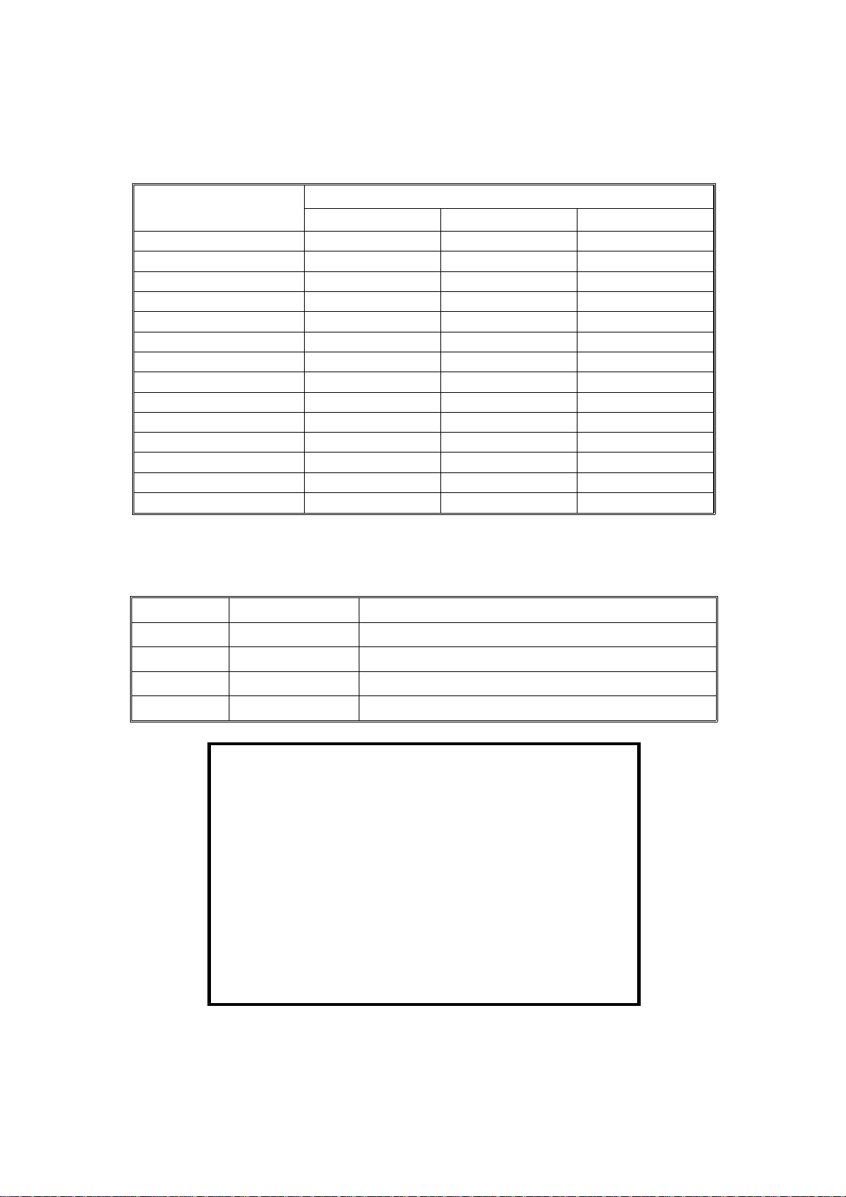
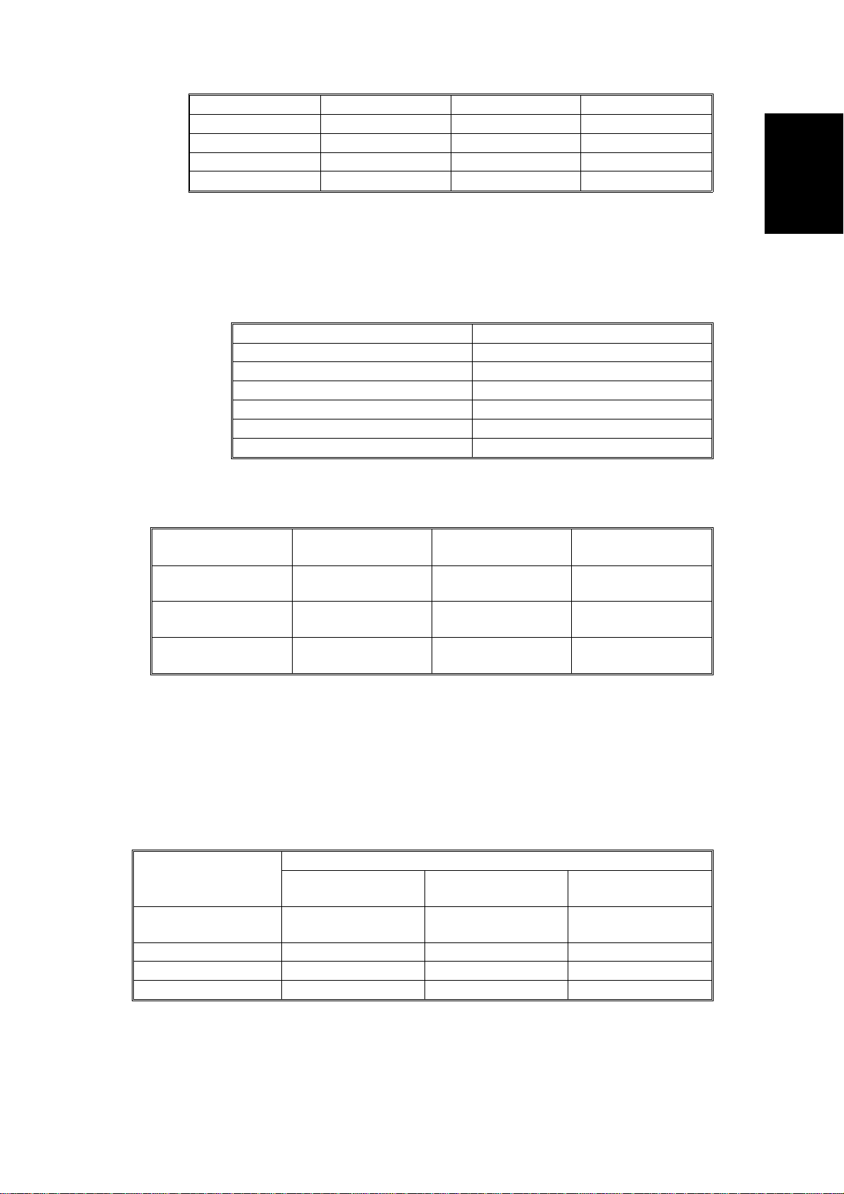
Power Consumption:
A153, and A156 copiers A157, and A160 copiers
Copier Only Full System Copier Only Full System
Maximum 1.45 KW 1.50 KW 1.45 KW 1.50 KW
Copying 1.00 KW 1.00 KW 0.80 KW 0.80 KW
Warm-up 0.90 KW 0.92 KW 0.90 KW 0.92 KW
Stand-by 0.16 KW 0.19 KW 0.15 KW 0.17 KW
1 0.15 KW 0.17 KW 0.14 KW 0.16 KW
Energy
Saver
Auto Off 0.02 KW 0.04 KW 0.02 KW 0.04 KW
2 0.13 KW 0.15 KW 0.12 KW 0.13 KW
3 0.12 KW 0.14 KW 0.09 KW 0.10 KW
4 0.11 KW 0.12 KW 0.07 KW 0.08 KW
5 0.09 KW 0.11 KW 0.05 KW 0.06 KW
6 0.07 KW 0.09 KW – –
NOTE:
Maximum 1.45 KW 1.50 KW
Copying 0.64 KW 0.72 KW
Warm-up 0.95 KW 0.97 KW
Stand-by 0.15 KW 0.17 KW
Energy Saver
Auto Off 0.02 KW 0.04 KW
NOTE:
1) Full System: Copier + ADF + Pap er Tr ay U nit + 20 Bin S/ S
2) Energy Saver: Se e SP 1-1 05 - 00 2
3) Auto Off: See SP5-305
A161 and A162 Copiers
Copier Only Full System
1 0.14 KW 0.16 KW
2 0.12 KW 0.13 KW
3 0.09 KW 0.10 KW
4 0.07 KW 0.08 KW
5 0.05 KW 0.06 KW
1) Full System: Copier + ADF + Pap er Tr ay U nit + 10 Bin S/ S
2) Energy Saver: Se e SP 1-1 05 - 00 2
3) Auto Off: See SP5-305
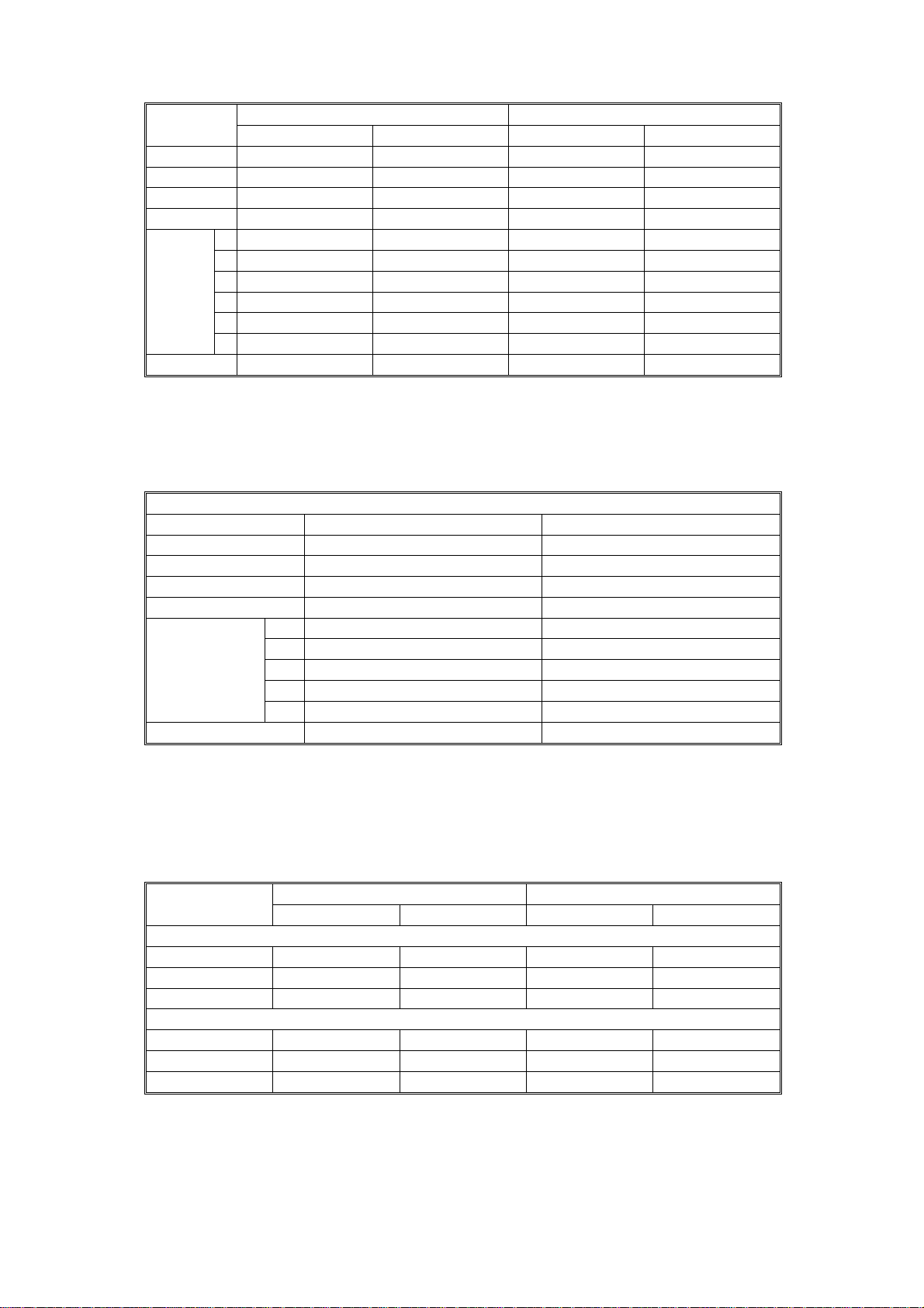
Noise Emission:
A153, and A156 copiers A157, and A160 copiers
Copier Only Full System* Copier Only Full System*
1. Sound Power Level
Copying 66 dB(A) 68 dB(A) 61 dB(A) 67 dB(A) (L
Warm-up 41 dB(A) 41 dB(A) 39 dB(A) 40 dB(A) (L
Stand-by 41 dB(A) 41 dB(A) 39 dB(A) 40 dB(A) (L
2. Sound Pressure Level at the operator position
Copying 58 dB(A) 57 dB(A) 54 dB(A) 56 dB(A) (L
Warm-up 33 dB(A) 27 dB(A) 32 dB(A) 27 dB(A) (L
Stand-by 33 dB(A) 27 dB(A) 32 dB(A) 27 dB(A) (L
NOTE:
The above measurements are to be made according to ISO 7779.
WA
WA
WA
PA
PA
PA
)
)
)
)
)
)
* : Full System: Copier + ADF + Paper Tray Unit +10 Bin S/S.
A156/A160/A162 1-2 STM
Dimensions:
A157/A161 copier 900 mm (35.5") 655 mm (25.8") 606 mm (23.9")
A160/A162 copiers 1128 mm (44.5") 655 mm (25.8") 606 mm (23.9")
Rev. 7/95
Width Depth Height
A153 copier 1030 mm (40.6") 655 mm (25.8") 606 mm (23.9")
A156 copiers 1258 mm (49.6") 655 mm (25.8") 606 mm (23.9")
Measurement Conditions
1) With by-pass feed tab le cl ose d
2) With platen cover and copy tray attached
3) With LCT cover closed
Weight:
Weight
FT5035 A153 copier About 70 kg (154.2 lb)
FT5535 A156 copier About 82 kg (180.7 lb)
FT4027 A157 copier About 67 kg (147.7 lb)
FT4527 A160 copier About 80 kg (176.4 lb)
FT4022 A161 copier About 67 kg (147.7 lb)
FT4522 A162 copier About 80 kg (176.4 lb)
Zoom: From 50% to 200% in 1% steps
Copying Speed (copies/minute):
A153, and A156
copiers
A157, and A160
copiers
A161, and A162
copiers
A4 sideways/
11" x 8
"
1/2
35 20/19 22
27 15/14 17
22 12 -
A3/11" x 17" B4/8
" x 14"
1/2
Information
Overall Machine
Warm-Up Time A153, and A156 copiers:
Less than 110 seconds (20°C)
A157, and A160 copiers:
Less than 80 seconds (20°C)
A161 and A162 copie rs:
Less than 60 seconds (20°C)
First Copy Time:
Paper Feed Station
1st Tray
2nd Tray 5.7 s 6.6 s 6.6 s
By-pass 4.8 s 5.6 s 5.6 s
LCT 5.0 s 5.9 s 5.9 s
Note:
In A156, A160 and A161 copiers, the 2nd tray in the above table is
A153, and A156
copiers
5.2 s (except for
A156)
A4/11" x 8
A157, and A160
5.9 s (except for
" (sideways)
1/2
copiers
A160)
A161, and A162
copiers
5.9 s (except for
A162)
called the 1st tray (see Installation - Paper Feed Station Definition).
STM 1-3 A156/A160/A162

Rev. 7/95
Copy Number Input: Ten-key pad, 1 to 999 (count up or count down)
Manual Image Density
7 steps
Selection:
Automatic Reset: 1 minute is the standard setting; it can be
changed to a maximum of 999 seconds or no
auto reset by SP mode.
Copy Paper Capacity:
Paper Tray By-pass Feed LCT
A153 copier About 500 sheets x2 About 40 sheets –
A156 copier About 500 sheets x1 About 40 sheets About 1000 sheets
A157 copier About 250 sheets x2 About 40 sheets –
A160 copier About 250 sheets x1 About 40 sheets About 1000 sheets
A161copier About 250 sheets x2 About 40 sheets –
A162 copier About 250 sheets x1 About 40 sheets About 1000 sheets
Duplex Tray Capacity
[A156/A160/A162]:
50 sheets (30 sheets for A3/11"x17"
81 ~ 105g/m2, 21.5 ~ 27.9 lb paper)
Toner Replenishment: Cartridge exchange (415 g/cartrid ge)
Toner Yield: 17K Copies/cartridg e
Developer Replenishment: Type 1 (1kg bag)
Developer Yield: A153/A156 @ 120K copies
A157/A160 @ 100K copies
A161/A162 @ 100K copies
Optional Eq uipment: • Platen cover
• Document feeder
• Paper tray unit wit h two paper trays
•
Paper tray unit wi th thr e e pa pe r tr ays
•
10 bin micro sorter
•
20 bin mini sorter
• 10 bin sorter staple r
• 20 bin sorter staple r (Not used with A161 and A1 62)
•
Sorter adapter (required when installing 20
bin mini sorter, 10 bin sorter stapler, or 20 bin
sorter stapl er for A157, A160, A161, and A162 copiers)
•
Key counter
•
Tray heater
•
Optical anti-condensation heater
•
Original length sensor for 11" x 15" size
paper (only for LT/DLT version)
•
ADS sensor for pa rticu lar typ es of red ori gina l
•
Zoom (10 Key) Function Decal *
•
Margin Adjustment Function Decal *
* Not used on FT4022/4522 (A161/A162 copiers)
A156/A160/A162 1-4 STM
 Loading...