

Page 1
RICOH FT5580/FT5590
RICOH COMPANY, LTD.
FIELD SERVICE MANUAL
Page 2

CONTENTS
INSTALLATION
Environment
Minimum Space Requirements
Machine Level
Power Source
Accessary Check
Installation Procedure
Cassette Modification
Key Counter Holder Installation
SERVICE TABLES
PM Tables
Service Tables
1. Test Points
2. Variable Resistors
3. DIP Switches Tables
4. User Codes Table
5. Service Program SP-8 Data Input Guide Table
Service Program Mode Operation
1. Service Program Access Procedure
2. Change Adjustment Values or Modes
3. Memory Clear Procedure
4. Service Program Mode Table
5. Language Code Table
Special Tools and Lubricants
Service Remarks
1. Handling the Drum
2. Charge Corona
3. Erase Lamp
4. Optics
5. Development Unit
6. Transfer and Separation Corona
7. Cleaning Unit
8. Pre-transfer & Quenching Unit
9. Fusing
10. Paper Feed and Duplex
11. Optional Equipment
12. Handling PCBs
. . . . . . . . . . . . . . . . . . . . . . . . . . . . . . . . . . . . . . . . . . . . . . . . . . . . . . . . . . . . . . . . . . . . . . . . . . . . . . . . . . . . . . . . . . . . . . . . . . . . .
. . . . . . . . . . . . . . . . . . . . . . . . . . . . . . . . . . . . . . . . . . . . . . . . . . . . . . . . . . . . . . . . .
. . . . . . . . . . . . . . . . . . . . . . . . . . . . . . . . . . . . . . . . . . . . . . . . . . . . . . . . . . . . . . . . . . . . . . . . . . . . . . . . . . . . . . . . . . . . . . . .
. . . . . . . . . . . . . . . . . . . . . . . . . . . . . . . . . . . . . . . . . . . . . . . . . . . . . . . . . . . . . . . . . . . . . . . . . . . . . . . . . . . . . . . . . . . . . . . .
. . . . . . . . . . . . . . . . . . . . . . . . . . . . . . . . . . . . . . . . . . . . . . . . . . . . . . . . . . . . . . . . . . . . . . . . . . . . . . . . . . . . . . . . .
. . . . . . . . . . . . . . . . . . . . . . . . . . . . . . . . . . . . . . . . . . . . . . . . . . . . . . . . . . . . . . . . . . . . . . . . . . . . . . . . . .
. . . . . . . . . . . . . . . . . . . . . . . . . . . . . . . . . . . . . . . . . . . . . . . . . . . . . . . . . . . . . . . . . . . . . . . . . . . . . . . . . .
. . . . . . . . . . . . . . . . . . . . . . . . . . . . . . . . . . . . . . . . . . . . . . . . . . . . . . . . . . . . . . .
. . . . . . . . . . . . . . . . . . . . . . . . . . . . . . . . . . . . . . . . . . . . . . . . . . . . . . . . . . . . . . . . . . . . . . . . . . . . . . . . . . . . . . . . . . . . . . . . . . . . . . .
. . . . . . . . . . . . . . . . . . . . . . . . . . . . . . . . . . . . . . . . . . . . . . . . . . . . . . . . . . . . . . . . . . . . . . . . . . . . . . . . . . . . . . . . . . . . . .
. . . . . . . . . . . . . . . . . . . . . . . . . . . . . . . . . . . . . . . . . . . . . . . . . . . . . . . . . . . . . . . . . . . . . . . . . . . . . . . . .
. . . . . . . . . . . . . . . . . . . . . . . . . . . . . . . . . . . . . . . . . . . . . . . . . . . . . . . . . . . . . . . . . . . . . . . . . . . .
. . . . . . . . . . . . . . . . . . . . . . . . . . . . . . . . . . . . . . . . . . . . . . . . . . . . . . . . . . . . . . . . . . . . . . . . . . . . . . . . .
. . . . . . . . . . . . . . . . . . . . . . . . . . . . . . . . . . . . . . . . . . . . .
. . . . . . . . . . . . . . . . . . . . . . . . . . . . . . . . . . . . . . . . . .
. . . . . . . . . . . . . . . . . . . . . . . . . . . . . . . . . . . . . . . . . . . . . . . . . . . . . . . . . . . . . . . . . . .
. . . . . . . . . . . . . . . . . . . . . . . . . . . . . . . . . . . . . . . . . . . . . . . . . . . . . . . . . .
. . . . . . . . . . . . . . . . . . . . . . . . . . . . . . . . . . . . . . . . . . . . . . . . . . . . . . . . . . . . . . . . . . . . . . . .
. . . . . . . . . . . . . . . . . . . . . . . . . . . . . . . . . . . . . . . . . . . . . . . . . . . . . . . . . . . . . . . . . .
. . . . . . . . . . . . . . . . . . . . . . . . . . . . . . . . . . . . . . . . . . . . . . . . . . . . . . . . . . . . . . . . . . . . . . . . . . . . . . . . .
. . . . . . . . . . . . . . . . . . . . . . . . . . . . . . . . . . . . . . . . . . . . . . . . . . . . . . . . . . . . . . . . . . . . . . . . . . . . . . . . . . . . . . .
. . . . . . . . . . . . . . . . . . . . . . . . . . . . . . . . . . . . . . . . . . . . . . . . . . . . . . . . . . . . . . . . . . . . . . . . . . . . . . . . . . . . . . . . . . . . .
. . . . . . . . . . . . . . . . . . . . . . . . . . . . . . . . . . . . . . . . . . . . . . . . . . . . . . . . . . . . . . . . . . . . . . . . . . . . . . . . . . . . . . . . . . . . . . . . . . . . . . .
. . . . . . . . . . . . . . . . . . . . . . . . . . . . . . . . . . . . . . . . . . . . . . . . . . . . . . . . . . . . . . . . . . . . . . . . . . . . . . . . . .
. . . . . . . . . . . . . . . . . . . . . . . . . . . . . . . . . . . . . . . . . . . . . . . . . . . .
. . . . . . . . . . . . . . . . . . . . . . . . . . . . . . . . . . . . . . . . . . . . . . . . . . . . . . . . . . . . . . . . . . . . . . . . . . . . . . . . . . . . . . . . . . .
. . . . . . . . . . . . . . . . . . . . . . . . . . . . . . . . . . . . . . . . . . . . . . . . . . . . . . . .
. . . . . . . . . . . . . . . . . . . . . . . . . . . . . . . . . . . . . . . . . . . . . . . . . . . . . . . . . . . . . . . . . . . . . . . . . . . . . . . . . . . . . . . . . . . . . . . . . . . . . . . .
. . . . . . . . . . . . . . . . . . . . . . . . . . . . . . . . . . . . . . . . . . . . . . . . . . . . . . . . . . . . . . . . . . . . .
. . . . . . . . . . . . . . . . . . . . . . . . . . . . . . . . . . . . . . . . . . . . . . . . . . . . . . . . . . . . . . . . . . . . . . . . . . . . .
. . . . . . . . . . . . . . . . . . . . . . . . . . . . . . . . . . . . . . . . . . . . . . . . . . . . . . . . . . . . . . . . . . . . . . . . . . . . . . . . . . . . . . .
12 June 1987
1- 1
1- 2
1- 3
1- 3
1- 4
1- 5
1-13
1-14
2- 1
2- 4
2- 4
2- 5
2- 5
. . . . . . . . . . . . . . . . . . . . . . . .
2- 6
2- 7
2- 7
2- 8
2-10
2-19
2-20
2-21
2-21
2-22
2-22
2-22
2-23
2-23
2-23
2-23
2-24
2-24
2-24
REPLACEMENT AND ADJUSTMENT
Optics
1. Exposure Glass Removal
2. Sixth Mirror Replacement
3. Scanner Drive Wire Replacement
4. Fourth and Fifth Mirror Drive Wire Replacement
5. Lens Drive Wire Replacement
. . . . . . . . . . . . . . . . . . . . . . . . . . . . . . . . . . . . . . . . . . . . . . . . . . . . . . . . . . . . . . . . . . . 3- 1
. . . . . . . . . . . . . . . . . . . . . . . . . . . . . . . . . . . . . . . . . . . . . . . . . . . . . . . . . . . . . . . . . .
. . . . . . . . . . . . . . . . . . . . . . . . . . . . . . . . . . . . . . . . . . . . . . . . . . .
. . . . . . . . . . . . . . . . . . . . . . . . . . . . . . . . . . . . . . . . . . . . . . . . . . . . . . . . . .
3- 2
3- 3
. . . . . . . . . . . . . . . . . . . . .
3- 7
3- 8
Page 3

12 June 1987
6. Scanner Harness Replacement
(Optics Cables & Exposure Lamp)
. . . . . . . . . . . . . . . . . . . . . . . . . . . . . . . . . . . . . . . . . . . . . . . .
3- 9
Development
1. Developer Replacement
2. Image Density Sensor Removal
3. Toner Collection Bottle Cleaning
4. Vsg Voltage Checking
5. Vsg Voltage Adjustment . . . . . . . . . . . . . . . . . . . . . . . . . . . . . . . . . . . . . . . . . . . . . . . . . . . . . . . . . . . . . . . . . . . . . 3-15
6. Toner Supply System Checking
7. Toner Density Recovery
8. Detect/Fixed Mode Selection
9. Toner Amount Changing
10. ID Pattern Bias Voltage Adjustment
. . . . . . . . . . . . . . . . . . . . . . . . . . . . . . . . . . . . . . . . . . . . . . . . . . . . . . . . . . . . . . . . . . . . .
. . . . . . . . . . . . . . . . . . . . . . . . . . . . . . . . . . . . . . . . . . . . . . . . . . . . . . .
. . . . . . . . . . . . . . . . . . . . . . . . . . . . . . . . . . . . . . . . . . . . . . . . . . . . .
. . . . . . . . . . . . . . . . . . . . . . . . . . . . . . . . . . . . . . . . . . . . . . . . . . . . . . . . . . . . . . . . . . . . . . . . .
. . . . . . . . . . . . . . . . . . . . . . . . . . . . . . . . . . . . . . . . . . . . . . . . . . . . . .
. . . . . . . . . . . . . . . . . . . . . . . . . . . . . . . . . . . . . . . . . . . . . . . . . . . . . . . . . . . . . . . . . . . . .
. . . . . . . . . . . . . . . . . . . . . . . . . . . . . . . . . . . . . . . . . . . . . . . . . . . . . . . . . . .
. . . . . . . . . . . . . . . . . . . . . . . . . . . . . . . . . . . . . . . . . . . . . . . . . . . . . . . . . . . . . . . . . . . . . .
. . . . . . . . . . . . . . . . . . . . . . . . . . . . . . . . . . . . . . . . . . . . .
3-11
3-12
3-13
3-14
3-16
3-17
3-17
3-17
3-17
Cleaning
1. Pick-off Pawl Replacement . . . . . . . . . . . . . . . . . . . . . . . . . . . . . . . . . . . . . . . . . . . . . . . . . . . . . . . . . . . . . . . 3-18
2. Cleaning Blade and Brush Replacement . . . . . . . . . . . . . . . . . . . . . . . . . . . . . . . . . . . . . . 3-20
3. Blade Cleaner and Bias Roller Blade Replacement . . . . . . . . . . . . . . . . . 3-21
Fusing
1. Fusing Unit Removal
2. Oil Blade Replacement
3. Thermistor Replacement . . . . . . . . . . . . . . . . . . . . . . . . . . . . . . . . . . . . . . . . . . . . . . . . . . . . . . . . . . . . . . . . . . . . 3-24
4. Thermofuse Replacement . . . . . . . . . . . . . . . . . . . . . . . . . . . . . . . . . . . . . . . . . . . . . . . . . . . . . . . . . . . . . . . . . . . 3-25
5. Hot Roller Stripper Replacement
6. Hot Roller Replacement
7. Pressure Roller Replacement
8. Entrance Guide Height Adjustment . . . . . . . . . . . . . . . . . . . . . . . . . . . . . . . . . . . . . . . . . . . . . . . . 3-30
9. Fusing Pressure Adjustment
10. Hot Roller Temperature Adjustment
11. Idling Period Selection . . . . . . . . . . . . . . . . . . . . . . . . . . . . . . . . . . . . . . . . . . . . . . . . . . . . . . . . . . . . . . . . . . . . . . . . 3-32
. . . . . . . . . . . . . . . . . . . . . . . . . . . . . . . . . . . . . . . . . . . . . . . . . . . . . . . . . . . . . . . . . . . . . . . . . . . . .
. . . . . . . . . . . . . . . . . . . . . . . . . . . . . . . . . . . . . . . . . . . . . . . . . . . . . . . . . . . . . . . . . . . . . . . .
. . . . . . . . . . . . . . . . . . . . . . . . . . . . . . . . . . . . . . . . . . . . . . . . . . . .
. . . . . . . . . . . . . . . . . . . . . . . . . . . . . . . . . . . . . . . . . . . . . . . . . . . . . . . . . . . . . . . . . . . . . .
. . . . . . . . . . . . . . . . . . . . . . . . . . . . . . . . . . . . . . . . . . . . . . . . . . . . . . . . . . .
. . . . . . . . . . . . . . . . . . . . . . . . . . . . . . . . . . . . . . . . . . . . . . . . . . . . . . . . . . . . .
. . . . . . . . . . . . . . . . . . . . . . . . . . . . . . . . . . . . . . . . . . . . .
3-22
3-23
3-26
3-27
3-29
3-31
3-32
Paper Feed
1. Pick-up, Paper Feed and Separation Rollers Replacement . . 3-33
2. Transport Unit Removal
. . . . . . . . . . . . . . . . . . . . . . . . . . . . . . . . . . . . . . . . . . . . . . . . . . . . . . . . . . . . . . . . . . . . . .
3-34
Duplex
1. Invertor Unit Removal
2. Duplex Transport and Fork Gate Units Removal . . . . . . . . . . . . . . . . . . . . . . 3-36
3. Jogger Unit Removal
4. Duplex Pick-up and Feed Rollers Replacement . . . . . . . . . . . . . . . . . . . . . . . . 3-38
5. Duplex Separation Roller Replacement
6. Positioning and Entrance Actuator Rollers Replacement . . . . . . 3-40
7. Duplex Pick-up Solenoid Adjustment
8. Jogger Wire Replacement . . . . . . . . . . . . . . . . . . . . . . . . . . . . . . . . . . . . . . . . . . . . . . . . . . . . . . . . . . . . . . . . . 3-42
. . . . . . . . . . . . . . . . . . . . . . . . . . . . . . . . . . . . . . . . . . . . . . . . . . . . . . . . . . . . . . . . . . . . . . . . . .
. . . . . . . . . . . . . . . . . . . . . . . . . . . . . . . . . . . . . . . . . . . . . . . . . . . . . . . . . . . . . . . . . . . . . . . . . . . .
. . . . . . . . . . . . . . . . . . . . . . . . . . . . . . . . . . . . . . . .
. . . . . . . . . . . . . . . . . . . . . . . . . . . . . . . . . . . . . . . . . . . . .
3-35
3-37
3-39
3-41
Copy Image
1. Vertical Magnification Adjustment
2. Horizontal Magnification
3. Focus Adjustment
4. Uneven Exposure Adjustment . . . . . . . . . . . . . . . . . . . . . . . . . . . . . . . . . . . . . . . . . . . . . . . . . . . . . . . . . . 3-46
5. Light Intensity Adjustment
6. Setting ADS Reference Voltage . . . . . . . . . . . . . . . . . . . . . . . . . . . . . . . . . . . . . . . . . . . . . . . . . . . . . . 3-47
7. ADS Voltage Adjustment
8. ADS Operation Checking
9. OW/OL Sensor Voltage Adjustment
10. OL Sensor Length Sensing Adjustment
11. Erase Adjustment . . . . . . . . . . . . . . . . . . . . . . . . . . . . . . . . . . . . . . . . . . . . . . . . . . . . . . . . . . . . . . . . . . . . . . . . . . . . . . . . . 3-51
12. Registration Adjustment . . . . . . . . . . . . . . . . . . . . . . . . . . . . . . . . . . . . . . . . . . . . . . . . . . . . . . . . . . . . . . . . . . . . . 3-52
. . . . . . . . . . . . . . . . . . . . . . . . . . . . . . . . . . . . . . . . . . . . . . . . . . . . . . . . . . . . . . . . . . . . . .
. . . . . . . . . . . . . . . . . . . . . . . . . . . . . . . . . . . . . . . . . . . . . . . . . . . . . . . . . . . . . . . . . . . . . . . . . . . . . . . . .
. . . . . . . . . . . . . . . . . . . . . . . . . . . . . . . . . . . . . . . . . . . . . . . . . . . . . . . . . . . . . . . .
. . . . . . . . . . . . . . . . . . . . . . . . . . . . . . . . . . . . . . . . . . . . . . . . . . . . . . . . . . . . . . . . . . .
. . . . . . . . . . . . . . . . . . . . . . . . . . . . . . . . . . . . . . . . . . . . . . . . . . . . . . . . . . . . . . . . . . .
. . . . . . . . . . . . . . . . . . . . . . . . . . . . . . . . . . . . . . . . . . . . . . . . . .
. . . . . . . . . . . . . . . . . . . . . . . . . . . . . . . . . . . . . . . . . . . . . .
. . . . . . . . . . . . . . . . . . . . . . . . . . . . . . . . . . . . . .
3-43
3-44
3-45
3-47
3-48
3-49
3-50
3-51
Page 4

Corona
and Exit Sensor Replacement
. . . . . . . . . . . . . . . . . . . . . . . . . . . . . . . . . . . . . . . . . . . . . . . . . . . . . . . . .
1. Charge Corona Wire Replacement
2. Pre-quenching Corona Wire Replacement
3. Transfer and Separation Corona Wires Replacement
4. Charge Cleaner Drive Wire Replacement
5. TC/SC Cleaner Drive Wire Replacement
6. Drum Current Adjustment Preparation
. . . . . . . . . . . . . . . . . . . . . . . . . . . . . . . . . . . . . . . . . . . . . . . . . . .
. . . . . . . . . . . . . . . . . . . . . . . . . . . . . . . . . . . . .
. . . . . . . . . . . . . . . . . . . . . . . . . . . . . . . . . . . . . .
. . . . . . . . . . . . . . . . . . . . .
. . . . . . . . . . . . . . . . . . . . . . . . . . . . . . . . . . . . . . . . . . .
Others
1. Power Supply Unit Removal
. . . . . . . . . . . . . . . . . . . . . . . . . . . . . . . . . . . . . . . . . . . . . . . . . . . . . . . . . . . . . .
ELECTRICAL DATA
3-53
3-55
. . . . . . . . . . . . . . .
. . . . . . . . . . . . . . . . .
3-56
3-57
3-58
3-59
3-66
1.
Main PCB Schematic
2.
Optics PCB Schematic
3.
Paper Feed PCB Schematic
4.
Timer PCB Schematic
5.
Timing Chart
6.
Sorter PCB Schematic
7.
ARDF PCB Schematic
8.
Large Capacity Tray Schematic - 1,000 sheets . . . . . . . . . . . . . . . . . . . . . . .
9.
Large Capacity Tray Schematic - 2,500 sheets
10.
15 Bin Sorter PCB Schematic
. . . . . . . . . . . . . . . . . . . . . . . . . . . . . . . . . . . . . . . . . . . . . . . . . . . . . . . . . . . . . . . . . . . . . . . . . . . . . . . . . . . . . . . . . . . . .
11. 15 Bin Sorter Timing Chart
. . . . . . . . . . . . . . . . . . . . . . . . . . . . . . . . . . . . . . . . . . . . . . . . . . . . . . . . . . . . . . . . . . . . . . . . . . . . . .
. . . . . . . . . . . . . . . . . . . . . . . . . . . . . . . . . . . . . . . . . . . . . . . . . . . . . . . . . . . . . . . . . . . . . . . . . .
. . . . . . . . . . . . . . . . . . . . . . . . . . . . . . . . . . . . . . . . . . . . . . . . . . . . . . . . . . . . . . . .
. . . . . . . . . . . . . . . . . . . . . . . . . . . . . . . . . . . . . . . . . . . . . . . . . . . . . . . . . . . . . . . . . . . . . . . . . . . .
. . . . . . . . . . . . . . . . . . . . . . . . . . . . . . . . . . . . . . . . . . . . . . . . . . . . . . . . . . . . . . . . . . . . . . . . . .
. . . . . . . . . . . . . . . . . . . . . . . . . . . . . . . . . . . . . . . . . . . . . . . . . . . . . . . . . . . . . . . . . . . . . . . . . . .
. . . . . . . . . . . . . . . . . . . . . . .
. . . . . . . . . . . . . . . . . . . . . . . . . . . . . . . . . . . . . . . . . . . . . . . . . . . . . . . . . . .
. . . . . . . . . . . . . . . . . . . . . . . . . . . . . . . . . . . . . . . . . . . . . . . . . . . . . . . . . . . . . . . . .
DOCUMENT FEEDER
Installation
1. Accessory Check
2. Installation Procedure
. . . . . . . . . . . . . . . . . . . . . . . . . . . . . . . . . . . . . . . . . . . . . . . . . . . . . . . . . . . . . . . . . . . . . . . . . . . . . . . . . .
. . . . . . . . . . . . . . . . . . . . . . . . . . . . . . . . . . . . . . . . . . . . . . . . . . . . . . . . . . . . . . . . . . . . . . . . . .
Replacement and Adjustment
1. DF Belt Drive Motor Speed Adjustment
. . . . . . . . . . . . . . . . . . . . . . . . . . . . . . . . . . . . . . . .
SORTER
Installation
1. Accessory Check
2. Installation Procedure
Replacement and Adjustment
1. Bin Drive Belt Replacement
2. Bin Drive Motor Replacement
3. Bin Replacement
4. Exit Roller Drive Motor Replacement
5. Lower Exit Roller Unit Replacement
. . . . . . . . . . . . . . . . . . . . . . . . . . . . . . . . . . . . . . . . . . . . . . . . . . . . . . . . . . . . . . . . . . . . . . . . . . . . . . . . . .
. . . . . . . . . . . . . . . . . . . . . . . . . . . . . . . . . . . . . . . . . . . . . . . . . . . . . . . . . . . . . . . . . . . . . . . . . .
. . . . . . . . . . . . . . . . . . . . . . . . . . . . . . . . . . . . . . . . . . . . . . . . . . . . . . . . . . . . . . .
. . . . . . . . . . . . . . . . . . . . . . . . . . . . . . . . . . . . . . . . . . . . . . . . . . . . . . . . . . .
. . . . . . . . . . . . . . . . . . . . . . . . . . . . . . . . . . . . . . . . . . . . . . . . . . . . . . . . . . . . . . . . . . . . . . . . . . . . . . . . . . . .
. . . . . . . . . . . . . . . . . . . . . . . . . . . . . . . . . . . . . . . . . . . . .
4- 1
4- 2
4- 3
4- 4
4- 5
4- 6
4- 7
4- 8
4- 9
4-10
4-11
5- 1
5- 2
5- 8
6- 1
6- 2
6- 5
6- 7
6- 8
6- 9
6-10
Page 5

LARGE CAPACITY TRAY (1,000 SHEETS)
Installation
1. Accessory Check
2. Installation Procedure
. . . . . . . . . . . . . . . . . . . . . . . . . . . . . . . . . . . . . . . . . . . . . . . . . . . . . . . . . . . . . . . . . . . . . . . . . . . . . . . . . .
. . . . . . . . . . . . . . . . . . . . . . . . . . . . . . . . . . . . . . . . . . . . . . . . . . . . . . . . . . . . . . . . . . . . . . . . . .
Replacement and Adjustment
Tray Down Sensor and Positioning Switch Replacement
1.
Paper Size Sensor Replacement
2.
Tray Wire Replacement
3.
4.
Paper Volume Cord Replacement
5.
Side Registration Adjustment
. . . . . . . . . . . . . . . . . . . . . . . . . . . . . . . . . . . . . . . . . . . . . . . . . . . . . . . . . . . . . . . . . . . . . . .
. . . . . . . . . . . . . . . . . . . . . . . . . . . . . . . . . . . . . . . . . . . . . . . . . . . . . .
. . . . . . . . . . . . . . . . . . . . . . . . . . . . . . . . . . . . . . . . . . . . . . . . . . . .
. . . . . . . . . . . . . . . . . . . . . . . . . . . . . . . . . . . . . . . . . . . . . . . . . . . . . . . . . . . .
LARGE CAPACITY TRAY (2,500 SHEETS)
Installation
1. Accessory Check
2. Installation Procedure
. . . . . . . . . . . . . . . . . . . . . . . . . . . . . . . . . . . . . . . . . . . . . . . . . . . . . . . . . . . . . . . . . . . . . . . . . . . . . . . . . .
. . . . . . . . . . . . . . . . . . . . . . . . . . . . . . . . . . . . . . . . . . . . . . . . . . . . . . . . . . . . . . . . . . . . . . . . . .
CASSETTE BANK
Installation
1. Accessory Check
2. Installation Procedure
. . . . . . . . . . . . . . . . . . . . . . . . . . . . . . . . . . . . . . . . . . . . . . . . . . . . . . . . . . . . . . . . . . . . . . . . . . . . . . . . . .
. . . . . . . . . . . . . . . . . . . . . . . . . . . . . . . . . . . . . . . . . . . . . . . . . . . . . . . . . . . . . . . . . . . . . . . . . .
TROUBLESHOOTING
Service Call Conditions
. . . . . . . . . . . . . . . . . . . . . . . . . . . . . . . . . . . . . . . . . . . . . . . . . . . . . . . . . . . . . . . . . . . . . . . . . . . . . .
. . . . . .
10- 1
7- 1
7- 2
7- 6
7- 8
7- 9
7-12
7-14
8- 1
8- 2
9- 1
9- 2
FT6620
Manual Level
Accessory Check
Installation Procedure
Optics
1. Exposure Glass Removal
Development
1. Developer Replacement
2. Toner Collection Bottle
Paper Feed
1. Pick-up, Paper Feed and Separation Roller Replacement . . . .
2. Transport Unit Removal
Duplex
1. Invertor Unit Removal
2. Duplex Transport and Fork Gate Unit Removal
3. Jogger Unit Removal
Others
1. Power Supply Unit Removal
. . . . . . . . . . . . . . . . . . . . . . . . . . . . . . . . . . . . . . . . . . . . . . . . . . . . . . . . . . . . . . . . . . . . . . . . . . . . . . . . . . . . . . . . . . . . . . . . . .
. . . . . . . . . . . . . . . . . . . . . . . . . . . . . . . . . . . . . . . . . . . . . . . . . . . . . . . . . . . . . . . . . . . . . . . . . . . . . . . . . . . . . . . . .
. . . . . . . . . . . . . . . . . . . . . . . . . . . . . . . . . . . . . . . . . . . . . . . . . . . . . . . . . . . . . . . . . . . . . . . . . . . . . . . . .
. . . . . . . . . . . . . . . . . . . . . . . . . . . . . . . . . . . . . . . . . . . . . . . . . . . . . . . . . . . . . . . . . .
. . . . . . . . . . . . . . . . . . . . . . . . . . . . . . . . . . . . . . . . . . . . . . . . . . . . . . . . . . . . . . . . . . . .
. . . . . . . . . . . . . . . . . . . . . . . . . . . . . . . . . . . . . . . . . . . . . . . . . . . . . . . . . . . . . . . . . . . . . .
. . . . . . . . . . . . . . . . . . . . . . . . . . . . . . . . . . . . . . . . . . . . . . . . . . . . . . . . . . . . . . . . . . . . .
. . . . . . . . . . . . . . . . . . . . . . . . . . . . . . . . . . . . . . . . . . . . . . . . . . . . . . . . . . . . . . . . . . . . . . . .
. . . . . . . . . . . . . . . . . . . . . . .
. . . . . . . . . . . . . . . . . . . . . . . . . . . . . . . . . . . . . . . . . . . . . . . . . . . . . . . . . . . . . . . . . . . . . . . . . .
. . . . . . . . . . . . . . . . . . . . . . . . . . . . . . . . . . . . . . . . . . . . . . . . . . . . . . . . . . . .
11- 1
11- 2
11- 3
11-14
11-15
11-16
11-17
11-18
11-19
11-20
11-21
11-22
Page 6

15 BIN SORTER
Installation
1. Accessory Check
2. Installation Procedure
. . . . . . . . . . . . . . . . . . . . . . . . . . . . . . . . . . . . . . . . . . . . . . . . . . . . . . . . . . . . . . . . . . . . . . . . . . . . . . . . . .
. . . . . . . . . . . . . . . . . . . . . . . . . . . . . . . . . . . . . . . . . . . . . . . . . . . . . . . . . . . . . . . . . . . . . . . . . .
Replacement and Adjustment
1. Sorter Removal
2. Inlet Sensor Replacement
3. Jam Sensor Replacement
4. Sponge Roller Replacement
5. DC Motor Replacement
. . . . . . . . . . . . . . . . . . . . . . . . . . . . . . . . . . . . . . . . . . . . . . . . . . . . . . . . . . . . . . . . . . . . . . . . . . . . . . . . . . . . . .
Service Table
1. LEDs
2. Dip Switch
3. Service Program Mode
. . . . . . . . . . . . . . . . . . . . . . . . . . . . . . . . . . . . . . . . . . . . . . . . . . . . . . . . . . . . . . . . . . . . . . . . . . . . . . . . . . . . . . . . . . . . . . . . . . . . . . . . . .
. . . . . . . . . . . . . . . . . . . . . . . . . . . . . . . . . . . . . . . . . . . . . . . . . . . . . . . . . . . . . . . . . . . . . . . . . . . . . . . . . . . . . . . . . . . . . . .
12- 1
12- 2
12- 7
. . . . . . . . . . . . . . . . . . . . . . . . . . . . . . . . . . . . . . . . . . . . . . . . . . . . . . . . . . . . . . . . . . .
. . . . . . . . . . . . . . . . . . . . . . . . . . . . . . . . . . . . . . . . . . . . . . . . . . . . . . . . . . . . . . . . . . .
. . . . . . . . . . . . . . . . . . . . . . . . . . . . . . . . . . . . . . . . . . . . . . . . . . . . . . . . . . . . . . .
. . . . . . . . . . . . . . . . . . . . . . . . . . . . . . . . . . . . . . . . . . . . . . . . . . . . . . . . . . . . . . . . . . . . . . .
. . . . . . . . . . . . . . . . . . . . . . . . . . . . . . . . . . . . . . . . . . . . . . . . . . . . . . . . . . . . . . . . . . . . . . . .
12- 8
12- 9
12-10
12-12
12-13
12-13
12-14
Page 7

SECTION 1
INSTALLATION
Page 8

CONTENTS
Environment . . . . . . . . . . . . . . . . . . . . . . . . . . . . . . . . . . . . . . . . . . . . . . . . . . . . . . . . . . . . . . . . . . . . . . . . . . . . . . . . . . . . . . . . . . . . . . . . . . . . .
Minimum Space Requirements
Machine Level . . . . . . . . . . . . . . . . . . . . . . . . . . . . . . . . . . . . . . . . . . . . . . . . . . . . . . . . . . . . . . . . . . . . . . . . . . . . . . . . . . . . . . . . . . . . . . . .
Power Source . . . . . . . . . . . . . . . . . . . . . . . . . . . . . . . . . . . . . . . . . . . . . . . . . . . . . . . . . . . . . . . . . . . . . . . . . . . . . . . . . . . . . . . . . . . . . . . .
Accessary Check
Installation Procedure . . . . . . . . . . . . . . . . . . . . . . . . . . . . . . . . . . . . . . . . . . . . . . . . . . . . . . . . . . . . . . . . . . . . . . . . . . . . . . . . . .
Cassette Modification . . . . . . . . . . . . . . . . . . . . . . . . . . . . . . . . . . . . . . . . . . . . . . . . . . . . . . . . . . . . . . . . . . . . . . . . . . . . . . . . . .
Key Counter Holder Installation
. . . . . . . . . . . . . . . . . . . . . . . . . . . . . . . . . . . . . . . . . . . . . . . . . . . . . . . . . . . . . . . . . . . . . . . . . . . . . . . . . . . . . . . . .
. . . . . . . . . . . . . . . . . . . . . . . . . . . . . . . . . . . . . . . . . . . . . . . . . . . . . . . . . . . . . . . . .
. . . . . . . . . . . . . . . . . . . . . . . . . . . . . . . . . . . . . . . . . . . . . . . . . . . . . . . . . . . . . . .
1- 1
1- 2
1- 3
1- 3
1- 4
1- 5
1-13
1-14
Page 9

ENVIRONMENT
1.
Temperature Range: 10°C to 30°C (50°F to 80°F)
12 June 1987
Humidity Range:
2.
3.
Ambient Illumination: Less than 1,500 Iux (Do not expose to
15% to 90% RH
direct sun light.)
4.
Ventilation: Room air should turn over at least 3
times/hour.
3
5.
Ambient Dust: Less than 0.15 mg/m
Room size More than 10 m
6.
If the place of installation is air-conditioned or heated, place the
7.
3
(4 x 10
(13.4 yd3)
machine:
a) where it will not be subjected to sudden
temperature changes
from low to high, or vice versa.
b) where it will not be directly exposed to
cool air from an air
conditioner.
where it will not be directly exposed to reflected heat from a
c)
heater.
Avoid placing the copier in an area filled with corrosive gas.
8.
Avoid any area higher that 2,000 m (6,500 feet) above sea level.
9.
10.
Place the copier on a strong and level base.
11.
Avoid any area where
the copier may be subjected to strong
vibration.
-3
Oz/yd3)
1-1
Page 10
12 June 1987
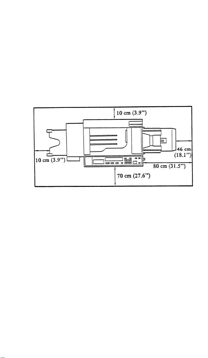
MINIMUM SPACE REQUIREMENTS
1-2
Page 11

Front to Back: Within 5 mm (0.2”) of level
1.
12 June 1987
Right to Left:
2.
3. Screw the leveling feet [A] up or down to level the machine.
Within 5 mm (0.2”) of level
POWER SOURCE
Input voltage Level
1.
110 V/60 Hz - 15A
115 V/60 Hz - 15A
220 V/50 Hz - 8A
240 V/50 Hz - 8A
Permissible Voltage Fluctuation : 10%
2.
Permissible Extension Cord : None recommended
3.
NOTE: -
Be sure to ground the machine.
grounding wire to a gas pipe.)
- Make sure the plug is firmly inserted in the outlet.
- Should be a dedicated power outlet.
- Do not set anything on the power cord.
(Do not connect the
1-3
Page 12

12 June 1987
ACCESSARY CHECK
Check the quantity and condition of the accessories in the box according
to the following list:
1. Editing Sheet
2. Sort/Stack Key Top
3. Sort/Stack Key Cover
4. NECR
5. Cassette -
6. Cassette - Small
7. Paper Size
Actuator Plate
8. Paper Size Decal
9. Toner Catch Pan
10. Copy Tray
11. Original Holder
12. Operating Instructions
- English
- Five languages
Large
USA
1
1
1
1
1
2
4
8
1
0
0
1
0
Europe
1
1
1
1
1
2
3
6
1
1
0
0
1
Middle East
& Asia
1
1
1
1
2
1
5
10
1
1
1
1
0
Taiwan
1
1
1
1
2
2
6
12
1
1
1
1
0
13. Envelope - NECR
14. Multiple Language
Decal
1-4
1
1
0
1
0
1
0
1
Page 13
INSTALLATION PROCEDURE
12 June 1987
NOTE:
-USA version-
The platen cover and the original stacker are needed as options
if DF is not to be installed.
sorter is not to be installed.
-European version-
The platen cover and the original stacker are needed as options
if DF is not to be installed.
is needed if one of the following optional languages is wanted on
the guidance display.
Option ROM
0: Swedish
1: English
2: Danish
3: Norwegian
4: Finnish
5: Dutch
(The English in both the optional and the standard ROMs are the
same.)
Standard ROM
0: Japanese
1: English
2: French
3: German
4: Italian
5: Spanish
Also, the copy tray is needed if the
Also, the guidance ROM kit (option)
1-5
Page 14
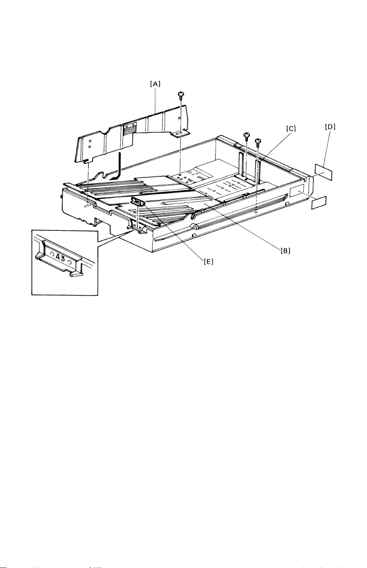
12 June 1987
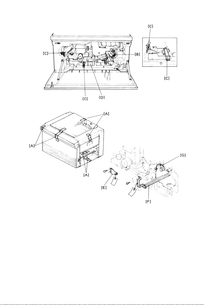
Remove the strips
1.
2.
Remove the strips
Non-duplex model
Duplex model
Remove the
3.
4.
Remove the
of tape [A], and open the front cover.
of tape as follows:
---
[B]
--- [B+C]
fork gate unit support cushion [D] (Duplex model only).
fork gate unit lock plate [E] (2 screws) (Duplex model
only).
5.
Remove the transport unit lock plate [F] (2 screws) and the wedge
[G] from between the registration rollers.
1-6
Page 15
12 June 1987
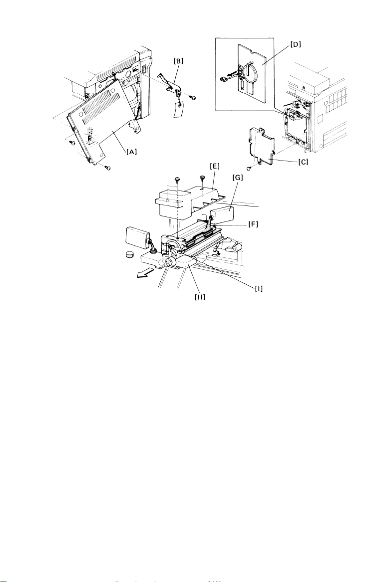
6. Remove the rear cover (2 screws), the left cover [A] (2 screws), and
the scanner lock plate [B] (1 screw).
NOTE:
Reinstall the screw for future use.
scanner lock plate.
It is necessary to reinstall it if the copier
Do not throw away the
is to be transported long distances (by vehicle).
7. Remove the main PCB shielding plate [C] (2 screws), and move the
jumper connector (JPSW 191) on the timer PCB [D] from the upper
(printed “OFF”) to the lower position. Then, reinstall the removed
covers if no peripherals are to be installed.
8. Remove the fusing unit,
then remove the fusing unit cover [E] (2
screws, 1 shoulder screw).
9. Prime the oil supply pad [F] with silicon oil [G]. Then, fill the oil tank
[H] with silicon oil.
10. Manually operate the oil pump lever [I] and confirm correct operation
and the overall condition of the silicon oil supply assembly.
Then,
reassemble the fusing unit.
1-7
Page 16
12 June 1987
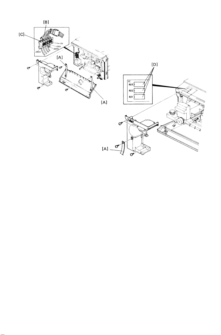
11. European version only:
-220 to 240 volts conversion-
a) Remove the support straps [A] (1 screw each), the front cover
(2 knob screws) and the left inner cover (4 screws).
b) Disconnect the wire from the 220 volt terminal [B], and connect
this wire to the 240 volt terminal [C] as shown.
-Guidance ROM kit installation-
a) Replace the three ROMs [D] (IC 821, 822 & 823) on the
operation panel with the ROMs of the guidance ROM kit.
b) Reinstall the right inner and the front covers.
1-8
Page 17
12 June 1987
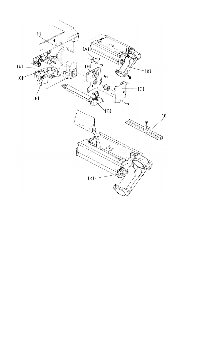
Reinstall the fusing
12.
Remove the image
13.
Pull down the toner bottle holder [B], lower the transport unit [C], and
14.
unit.
density sensor cover [A].
remove the drum inner cover [D] (1 screw).
Put a sheet of paper [E] on the T/S corona unit [F].
15.
Remove the charge corona unit [G] (2 connectors), and remove the
16.
drum stay [H] (1 screw, knob - reverse thread).
17.
Place a sheet of paper on the floor.
Raise the development unit lock
lever [I], remove the development unit, and place it on the paper.
18.
Remove the developer inlet cover [J] (1 screw).
19.
Pour one kilogram of developer into the development unit while
turning the knob [K] counterclockwise to distribute the developer.
20.
Reinstall the developer inlet cover.
1-9
Page 18
12 June 1987
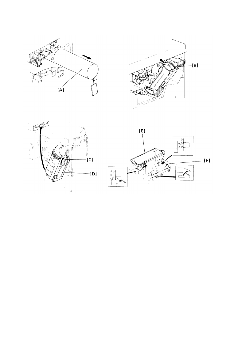
21.
Pull out the drum protective sleeve [A] from the drum.
NOTE:
Save the drum protective
sleeve for future use when
servicing the copier.
Reinstall all removed parts, and return them to their original position.
22.
Remove the toner tank plug [B] and load the toner bottle onto the
23.
bottle holder.
Then, fix the bottle with the lever [C], and raise the
holder [D] up to the bracket.
Install the toner catch pan [E] on the jogger unit [F].
24.
1-10
Page 19
12 June 1987
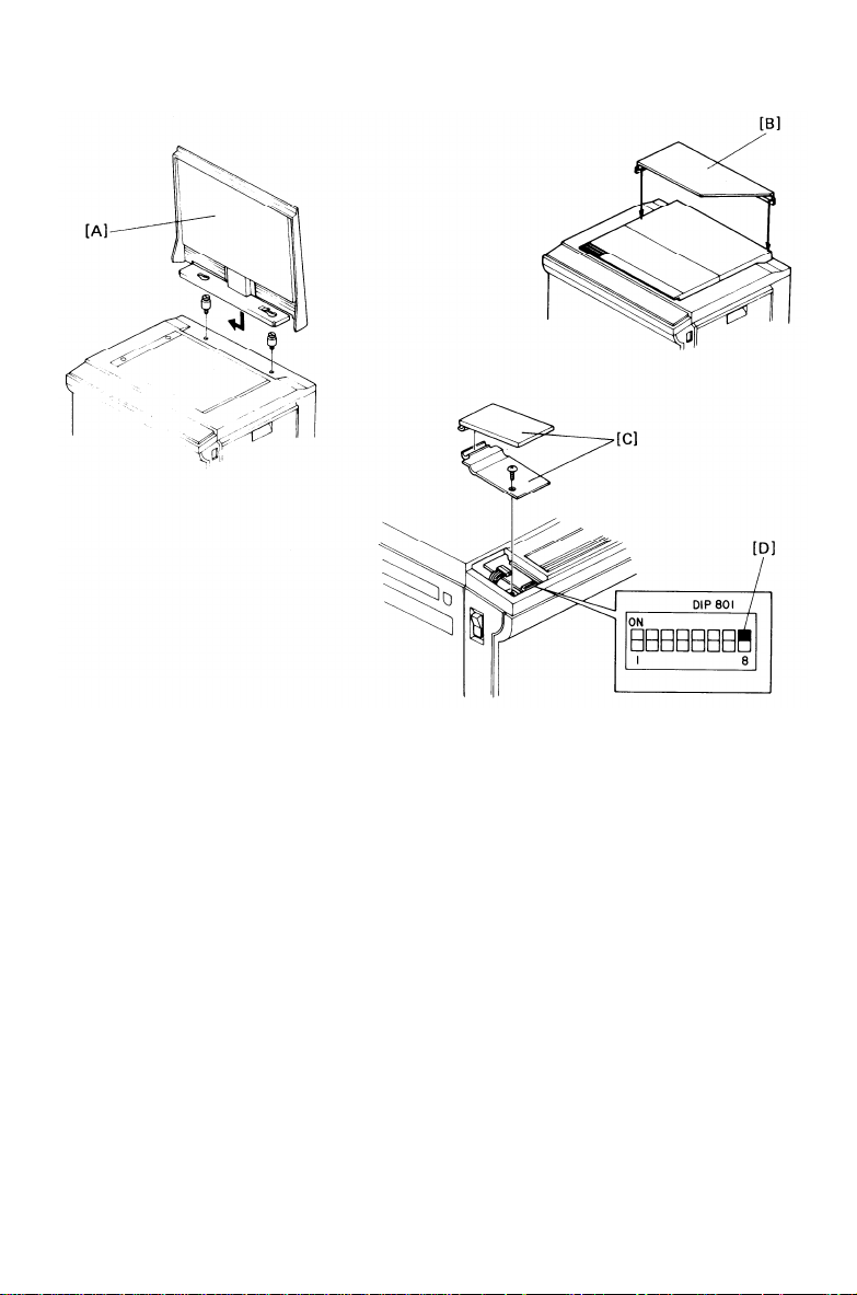
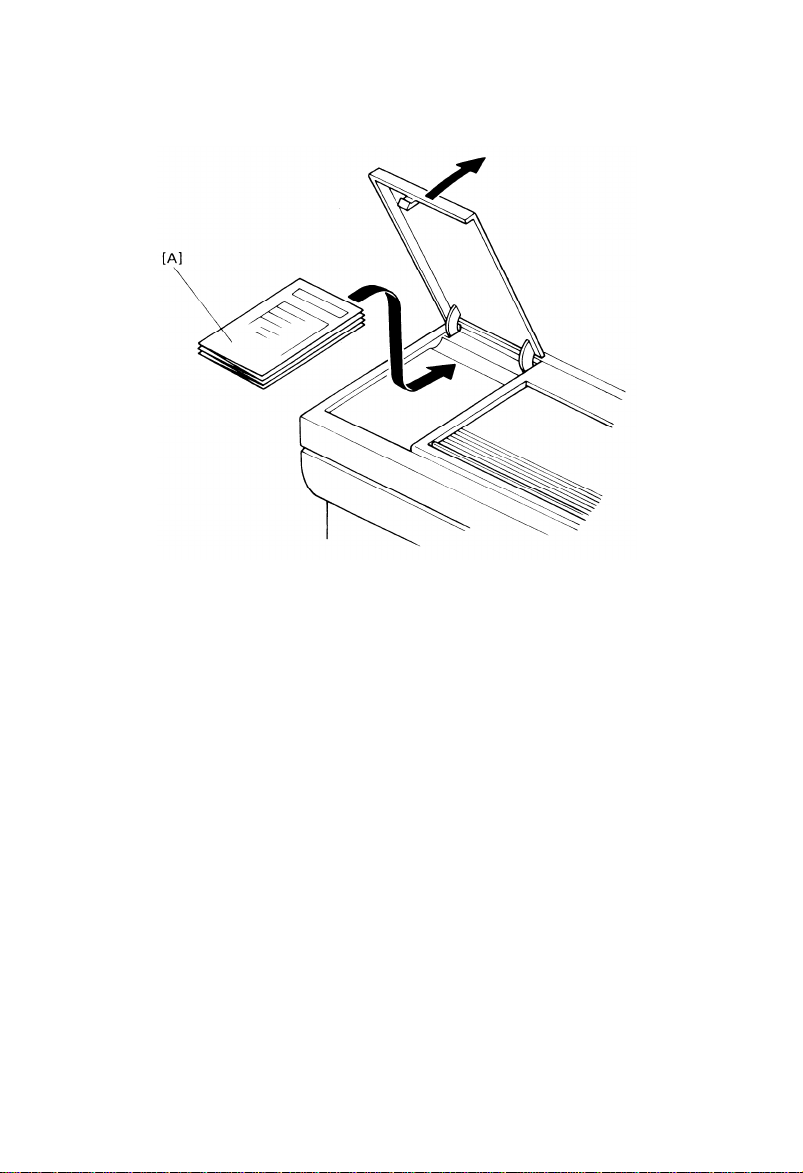
25.
Install the platen cover [A] (2 stud screws) and the original holder [B]
(Two sided tape) as necessary.
26.
Remove the DIP switch cover [C] (1 screw), and turn on DIP switch
801-8 [D]. Then, plug in the machine and turn on the main switch.
27.
Set the proper language in the guidance display using SP 12 (LT
Version) or SP 13 (A4 Version).
To access SP (Service program mode), enter 12 or 13 using the
number keys.
Press the Recall/Enter key.
1-11
Page 20
12 June 1987
28.
Put five sheets of white paper (A3 of 11” x 17”) on the exposure
glass.
Set SP 10 for drum conditioning.
29.
30.
After the warm up period is completed, press the Start Key to start
drum conditioning.
(100 is automatically displayed on the copy
counter by SP 10.)
31.
Set all appropriate SP modes as required.
Turn off the main switch the DIP switch 801-8, and reinstall the DIP
32.
switch cover. Then, turn on the main switch.
33.
Install the operating instruction cards [A] over the DIP switch cover
(two-sided tape). Then, install the receiving tray.
34.
Load paper into the cassette, then check the machine operation and
the copy quality.
35.
Fill out the New Equipment Condition Report.
1-12
Page 21
CASSETTE MODIFICATION
12 June 1987
1. Remove the cassette cover.
2. Remove the side fences [A] (1 screw each) and the bottom plate [B].
3. Reposition the rear fence [C] (1 screw) in the desired paper size
position.
NOTE:
4. Reinstall the bottom plate.
5. Reinstall the side fences in the desired paper size position.
6. Attach the appropriate paper size decals [D] on the cassette at the
positions shown.
7. Insert the desired actuator plate [E] in the slot on the front of the
cassette as shown.
Paper size positions are shown on the inside of the cassette.
1-13
Page 22
12 June 1987
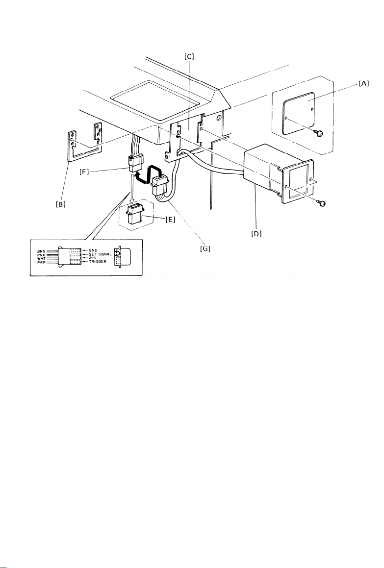
KEY COUNTER HOLDER INSTALLATION
Remove the front cover (2 screws).
1.
Remove the right inner cover (4 screws) and right front cover (1
2.
screws).
3.
Remove the cover plate [A] and fixing plate [B] from the key counter
bracket [C].
4.
Hold the fixing plate on the inside of the key counter bracket and
insert the key counter bracket. Insert the key counter holder [D].
5.
Align the holes in the fixing pIate with the mounting holes of the key
counter holder and secure the key counter holder.
NOTE:
Remove the shorting plug [E] from the key counter connector [F].
6.
Plug in the key counter harness [G].
7.
Reassemble the copier.
8.
operation.
NOTE:
The fixing plate has three sets of holes. Make sure to use
the holes that match the type of counter.
Insert the key counter and check
Confirm that SP 90 (Secret mode) is set in “No” position.
1-14
its
Page 23

SECTION 2
SERVICE TABLES
Page 24

CONTENTS
PM Tables . . . . . . . . . . . . . . . . . . . . . . . . . . . . . . . . . . . . . . . . . . . . . . . . . . . . . . . . . . . . . . . . . . . . . . . . . . . . . . . . . . . . . . . . . . . . . . . . . . . . . . .
2- 1
Service Tables
1. Test Points
2. Variable Resistors
3. DIP Switches Tables
4. User Codes Table . . . . . . . . . . . . . . . . . . . . . . . . . . . . . . . . . . . . . . . . . . . . . . . . . . . . . . . . . . . . . . . . . . . . . . . . . . . . . . . . .
5. Service Program SP-8 Data Input Guide Table . . . . . . . . . . . . . . . . . . . . . . . .
. . . . . . . . . . . . . . . . . . . . . . . . . . . . . . . . . . . . . . . . . . . . . . . . . . . . . . . . . . . . . . . . . . . . . . . . . . . . . . . . . . . . . . . . . . . . . .
. . . . . . . . . . . . . . . . . . . . . . . . . . . . . . . . . . . . . . . . . . . . . . . . . . . . . . . . . . . . . . . . . . . . . . . . . . . . . . . . .
. . . . . . . . . . . . . . . . . . . . . . . . . . . . . . . . . . . . . . . . . . . . . . . . . . . . . . . . . . . . . . . . . . . . . . . . . . . .
2- 4
2- 4
2- 5
2- 5
2- 6
Service Program Mode Operation
1. Service Program Access Procedure . . . . . . . . . . . . . . . . . . . . . . . . . . . . . . . . . . . . . . . . . . . . .
2. Change Adjustment Values or Modes
3. Memory Clear Procedure
4. Service Program Mode Table . . . . . . . . . . . . . . . . . . . . . . . . . . . . . . . . . . . . . . . . . . . . . . . . . . . . . . . . . .
5. Language Code Table . . . . . . . . . . . . . . . . . . . . . . . . . . . . . . . . . . . . . . . . . . . . . . . . . . . . . . . . . . . . . . . . . . . . . . . .
Special Tools and Lubricants
. . . . . . . . . . . . . . . . . . . . . . . . . . . . . . . . . . . . . . . . . . . . . . . . . . . . . . . . . . . . . . . . . . .
. . . . . . . . . . . . . . . . . . . . . . . . . . . . . . . . . . . . . . . . . . . . . . . . . . . . . . . . . . . . . . . . .
. . . . . . . . . . . . . . . . . . . . . . . . . . . . . . . . . . . . . . . . . .
2- 7
2- 7
2- 8
2-10
2-19
2-20
Service Remarks
1. Handling the Drum
2. Charge Corona
3. Erase Lamp
4. Optics
5. Development Unit
6. Transfer and Separation Corona
7. Cleaning Unit
8. Pre-transfer & Quenching Unit . . . . . . . . . . . . . . . . . . . . . . . . . . . . . . . . . . . . . . . . . . . . . . . . . . . . . . . .
9. Fusing
10. Paper Feed and Duplex
11. Optional Equipment
12. Handling PCBs
. . . . . . . . . . . . . . . . . . . . . . . . . . . . . . . . . . . . . . . . . . . . . . . . . . . . . . . . . . . . . . . . . . . . . . . . . . . . . . . . . . . . . . . . . . . . . . . . . . . . . . .
. . . . . . . . . . . . . . . . . . . . . . . . . . . . . . . . . . . . . . . . . . . . . . . . . . . . . . . . . . . . . . . . . . . . . . . . . . . . . . . . . . . . . . . . . . . . . . . . . . . . . . . .
. . . . . . . . . . . . . . . . . . . . . . . . . . . . . . . . . . . . . . . . . . . . . . . . . . . . . . . . . . . . . . . . . . . . . . . . . . . . . . . . .
. . . . . . . . . . . . . . . . . . . . . . . . . . . . . . . . . . . . . . . . . . . . . . . . . . . . . . . . . . . . . . . . . . . . . . . . . . . . . . . . . . . . . . .
. . . . . . . . . . . . . . . . . . . . . . . . . . . . . . . . . . . . . . . . . . . . . . . . . . . . . . . . . . . . . . . . . . . . . . . . . . . . . . . . . . . . . . . . . . . . .
. . . . . . . . . . . . . . . . . . . . . . . . . . . . . . . . . . . . . . . . . . . . . . . . . . . . . . . . . . . . . . . . . . . . . . . . . . . . . . . . . .
. . . . . . . . . . . . . . . . . . . . . . . . . . . . . . . . . . . . . . . . . . . . . . . . . . . .
. . . . . . . . . . . . . . . . . . . . . . . . . . . . . . . . . . . . . . . . . . . . . . . . . . . . . . . . . . . . . . . . . . . . . . . . . . . . . . . . . . . . . . . . . . .
. . . . . . . . . . . . . . . . . . . . . . . . . . . . . . . . . . . . . . . . . . . . . . . . . . . . . . . . . . . . . . . . . . . . .
. . . . . . . . . . . . . . . . . . . . . . . . . . . . . . . . . . . . . . . . . . . . . . . . . . . . . . . . . . . . . . . . . . . . . . . . . . . . .
. . . . . . . . . . . . . . . . . . . . . . . . . . . . . . . . . . . . . . . . . . . . . . . . . . . . . . . . . . . . . . . . . . . . . . . . . . . . . . . . . . . . . . .
2-21
2-21
2-22
2-22
2-22
2-23
2-23
2-23
2-23
2-24
2-24
2-24
Page 25

C: Clean R: Replace L: Lubricate A: Add I: Inspect
ITEM
OPTICS
Mirrors, Lens Reflectors,
Toner Shield Glass
Exposure Glass
Platen Cover
Exposure Lamp
Scanner Guide Rods
and Plate
Guide Rod Felt
ADS/APS Sensors
EM
C
C
C
80k
C
C
C
I
C,L
I
C
160k
C,L
12 June 1987
240k
320k
C
C
C
C
I
C,L
I
C
C
C
C
C
C
I
I
C,L
I
I
C
C
NOTE
Alcohol/Water
Glass Cleaner
Alcohol/Water
Replace if necessary
Launa Oil
Replace if necessary
Blower Brush Only
PAPER FEED
Paper Feed Rollers
Pick-up Rollers
Separation Rollers
Slip Clutch
Registration Roller
Lift Motor Worm Gear
and Worm Wheel
Paper Feed Guide Plate
Registration Sensor
Cassette Bottom Plate
Pad
Paper Dust Cleaner
Relay Rollers
AROUND DRUM
Corona Wires
Wire Cleaner Pad
End Blocks and Casing
Cleaner Drive Wire
PTL Filter
QL Filter
ID Sensor
Erase Lamp Unit
R
R
C
R
C
R
C
L
C
L
C
C
C
C
C
I
R
C
C
I
C
C
R
R
R
R
R
L
L
C
C
L
L
C
C
C
C
C
C
C
C
C
C
I
I
R
R
C
C
I
I
C
C
Damp Cloth
R
R
Damp Cloth
Damp Cloth
R
L
Mobil Temp.78
C
Damp Cloth
L
Mobil Temp.78
C
Damp Cloth
C
Blower Brush
C
Damp Cloth
C
Damp Cloth
C
I
Replace if necessary
R
Dry Cloth
C
Replace if necessary
I
C
Dry Cloth, Discharge
before installation
C
C
C
C
Dry cloth, Discharge
C
before installation
C
C
C
C
C
C
C
C
C
Blower Brush
Dry Cloth
2-1
Page 26

12 June 1987
ITEM
EM
80k
160k
CLEANING UNIT
Cleaning Blade
Cleaning Seals
Cleaning Brush
Bias Roller
Bias Roller Blade
Pick-off Pawls
R R R
I I
R R R
I I I
C
C
I I I I
DEVELOPMENT UNIT
Developer
Upper Brush Seal
R R R R
C
C
Development Unit Drive
Gears
Development Filter
L L
R R R R
FUSING UNIT
Hot Roller
Pressure Roller
Stripper Pawls
Oil Supply Pad
Oil Blade
I
I
I
R
R
C C C C
R R R R
R R
Fusing Entrance &
Exit Guide
Oil Sump
Oil Tank
C C
C
C
A A A A A
Gears L L L
OTHERS
Transport Ozone Filter
R R R
Registration Roller
Gears L
First Relay Roller Gears
First Relay Rollers
Drive Chains and Belts
Transport Belt
Vacuum Fan Filter
Exit Relay Rollers
Bushings
L
L L
C C C C
I I I
C C C
R
R
C C C C
L
240k 320k
R
I I
R
I
R C
C C
L
L
R
R
C
C
C C
L
R
L
L
L
L
I
C
R R
L
NOTE
Clean or replace if
necessary
Clean if necessary
Dry Cloth
Clean if necessary
Mobil Temp.78
Prime with oil when
replacing
Prime with oil when
replacing
Suitable Solvent
Mobil Temp.78
Mobil Temp.78
Mobil Temp.78
Damp Cloth
Replace if necessary
Damp Cloth
Damp Cloth
2-2
Page 27
12 June 1987
ITEM
DUPLEX
Inverter Support Roller
lnverter Pressure Roller
Positioning Roller Drive
Belt
Positioning Roller
Duplex Slip Clutch
Duplex Pick-up Roller
Duplex Separation Roller
Duplex Feed Roller
DOCUMENT FEEDER
Belt
Pick-up Roller
Feed Roller
Friction Roller
CASSETTE BANK
Pick-up Roller
Feed Roller
Friction Roller
EM
80k
C
C
C
C
240k 320k
160k
C C
C C C
C C C
R C R
L L L
C C
C
C
C
C
C
C
R
R C R
R C
C C
C C R C
C
C
R
C C R C
C C
C
C
C
C
R
R C R
R C R
NOTE
Damp Cloth
C
Damp Cloth
Damp Cloth
Damp Cloth
Mobil Temp.78
C
L
R
Damp Cloth
Damp Cloth
Damp Cloth
R
Belt cleaner,
C
replace if necessary
Water, replace if
R
necessary
C
R
Water, replace if
necessary
Water, replace if
R
necessary
C
R
Water, replace if
necessary
Water, replace if
necessary
Water, replace if
necessary
2-3
Page 28

12 June 1987
SERVICE TABLES
1. Test Points
- Main Board Number
TP100 Input voltage of image density sensor.
TP101
TP102
TP103
- Scanner Control Number
TP301
TP303
TP304
TP305
TP306
TP307
TP308
TP309
TP310
TP311
TP312
Function
+24 V
+5 V
GND
Function
+24 V (Vm)
Factory Use
Factory Use
Factory Use
Factory Use
Factory Use
Original Density Voltage
Scanner Forward Signal (Low Active)
Scanner Return Signal (Low Active)
GND
+5 V (Vc)
2. Variable Resistors
- ID Sensor Board VR
Function
VR-1
- Main Board VR
VR-100
- Optics Control Board VR
VR-301 APS Width Sensor (OWS) Voltage Adjustment
VR-302
LED Light Intensity Adjustment
Function
ADS Voltage Adjustment
Function
APS Length Sensor (OLS) Voltage Adjustment
2-4
Page 29

3. DIP Switches Tables
DIP SW 801 (Operation panel)
12 June 1987
SW #
1*
2
Description
Free run
Not used
3
4
Language code (see language code table)
5
6
7
Not used
Clear counter (see CLEAR MEMORY PROCEDURE)
8 Service Program mode access
* When ON, the SP mode is disabled.
DIP SW 100 (Main Board)
SW #
1
2
3
Description
Factory use only (must be off)
Factory use only (must be off)
Disables the oil end sensor operation
4,5
6,7
Not used
8
RAM clear (See CLEAR MEMORY PROCEDURE)
4. User Codes Table
There are 20 user codes as follows:
1.
2.
3.
4.
5.
6.
7.
8.
9.
10.
1101
1202
1303
1404
1505
1606
1707
1808
1909
2010
11. 2111
12. 2212
13. 2313
14. 2414
15. 2515
16. 2616
17. 2717
18. 2818
19. 2919
20. 3020
2-5
Page 30

12 June 1987
5. Service Program SP-8 Data Input Guide Table INPUT #
1
2
3
4
5
6
8
9
10
11
12
15
16
17
18
20
21
24
SENSOR
DATA
Registration sensor
Fuser sensor
Exit sensor
Relay roller sensor #1
Relay roller sensor #2
Relay roller sensor #3 DATA 1 . .
When paper is present
Inverter entrance sensor
Inverter exit sensor
DATA 0 . . When paper is not
Duplex entrance sensor present
Duplex paper sensor
Jogger home position DATA 0 . . Jogger at H.P.
Sorter inlet sensor
Sorter bin sensor DATA 0 . . Paper not present
Sorter home position
DATA 1 . .
Bins at H.P.
sensor
Sorter door safety switch
Toner end sensor
DATA 0 . . Sorter door closed
DATA 1 . . Toner present
Total counter confirmation DATA 0 . . Confirmation signal
signal
LOW (T.C. off)
Pressure pIate reed switch DATA 1 . . Pressure plate down
25
27
30
31
32
33
35
Paper bank set signal
Duplex unit set signal
Paper lift sensor #1
Paper lift sensor #2
Paper lift sensor #3
Paper lift sensor #4
Cassette release sensor
DATA 1 . . Paper bank installed
DATA 1 . . Duplex unit installed
DATA 1 . . Cassette lifted
DATA 0 . . Cassette down
DATA 1 . . Cassette #1 released
For all sensors, DATA is displayed in the guidance display.
2-6
Page 31

12 June 1987
SERVICE PROGRAM MODE OPERATION
The service program mode is used to check electrical data and change
modes or adjustment values.
1. Service Program Access Procedure
1.
Turn the main switch off.
Remove the DIP switch cover on the Operation Panel and turn on DIP
2.
SW 801-8, then turn the main switch on.
NOTE:
3.
Using the numeric key board, enter the desired SP mode number
according to the Service Program Mode Table. The SP program can
also be selected with the magnification keys (+, -), in this case SP
numbers are scanned through. After selecting an SP number, press
the ENTER key (#).
NOTE:
To abandoned SP mode, turn the main switch OFF, set DIP SW 801-8
4.
to the off position, and turn the main switch on.
At this point the guidance display will prompt...
“PROGRAM No.” . . . . . . . . . . . . . . No. 5
To cancel an already entered program, press the clear key.
Also, if an invalid SP number is entered, “Press Clear key” is
displayed.
—
2. Change Adjustment Values or Modes
1.
Follow steps 1-3 of the preceding procedure.
Factory setting values or mode will be displayed in the Guidance
2.
Display.
Enter the desired value or mode using the numeral keys according to
3.
the Service Program Mode table.
Turn off the main switch, set DIP SW 801-8 to the off position, and
4.
turn the main switch on.
The
following procedure can also be used to access program numbers 80, 81, 90, 91,
92 instead of using DIP SW 801-8.
and
1.
Press the Mode Clear key.
Press the Clear/Stop key.
2.
Press the Enter key, simultaneously the Guidance Display prompts
3.
“PROGRAM No.” . . . . . . . NO. 80
2-7
Page 32

4. Enter the desired number using the number keys or zoom keys.
5. Press the Enter key.
• Service program mode is cleared by pressing the Clear Modes key.
3. Memory Clear Procedure
<SP-97 “Clears service counters and jam counters”>
Service Program SP-97 is used to clear all self-diagnostic counters and
paper jam counters.
To perform this clear function,
performed.
1.
Turn main switch OFF
Turn ON DIP SW 801-7, 8 on the operation panel and turn the main
2.
switch ON.
Select Service program SP-97 and and press the “1” key on the key
3.
pad, then press the Enter key.
At this point Service Programs SP-120 through 139 will be cleared,
and default to “0”
Turn off the main switch.
4.
5.
Turn DIP SW 801-7 and 8 off.
Turn the main switch ON to resume normal copier operation.
6.
<SP-98 “Clears all counters”>
Service Program SP-98 is used to clear all copy counter, self-diagnostic
counters and jam counters at once.
To perform this clear function, follow the same procedure as previously
describe but using SP-98 instead.
The following programs will be cleared:
the following procedure must be
1) SP-100 through SP-139
2) SP-85 (E.M. call telephone number)
3) SP-86 through SP-89 (PM counter)
4) All User Programs are cleared
2-8
Page 33

5) Secret Mode counters 1-20 are cleared.
<SP-99 “Clear all memory”>
12 June 1987
This Service Program
clears all those service programs previously
described as well as all adjustments and modes. All mode default to
factory settings.
1. Turn the main switch OFF
2. Turn on DIP SW 801-7 and 8 on the operation board.
3. Turn on DIP SW 100-8 on the main board.
4. Turn the main switch on.
5. Select SP-99 and press the
“1” key on the key pad, then press the
Enter key to perform memory clear function.
6. Turn the main switch OFF and reset DIP switches to the OFF
position, then turn the main ON to resume copier operation.
2-9
Page 34

12 June 1987
4. Service Program Mode Table
Mode No.
5 Exposure Lamp
OFF Free Run
6 Jam Detection
OFF
7 Corona wire
cleaner function
8 Input Check
10 Drum Condi-
tioning
11 All Indicators
ON
12 Language (LT
version only)
13 Language (A4
version only)
Function
Free run with exposure lamp OFF.
Copies are made
without jam detection.
CC/TC cleaner motors
operation.
Displays the input
from sensors.
Used to condition a
new drum.
Turns on all the indicators on the operation panel.
Selects desired language. (French or
English
Selects language.
(Japanese, English
French, German,
Italian and Spanish)
Data
0: E
1: F
0: J
1: E
2: F
3: G
4: I
5: S
Factory
Setting
0: E
“No” is displayed
when 0 is selected.
The motor starts
when Enter key is
pressed. Stops after
1 cycle.
For data, see the
input check table.
100 will appear in the
copy counter. Press
Start to activate.
DIP SW 801-3, 4, 5
must be set. See
DIP SW tables.
DIP SW 801-3, 4, 5
must be set. See
DIP SW tables.
15 Auto Reset
Time
16 Count Up/Down
17 Auto cassette
shift
Selects auto reset
of 1 or 3 minutes.
Selects count up
or count down.
Selects autocassette shift
mode.
2-10
0: 1 min.
1: 3 min.
2: none
0: UP
1: DOWN
0: YES
1: NO
0
0
Copier automatically
0
shifts to another
cassette holding same
size paper when paper
runs out.
Page 35

12 June 1987
Mode No.
18 Beeper
19 Auto ID
Priority
20 Feed Station
Priority
21 APS Priority
22 SADF Shut-Off
Time
23 Free Size
24 RDH/ARDF
priority
25 Staple limit
Function
Turns beeper ON
or OFF.
Selects the priority
of image density
control when the main
switch is turned on.
Selects feed station
priority at power on.
Selects APS or
manual.
Selects shut-off time
for SADF mode.
Enables originals of
various sizes to be
fed from the same
stack.
Selects RDH or ARDF.
Sets staple limit at
35 copies.
Data
0: YES
1: NO
0: ADS
1: Manual
0: 1st
1: 2nd
(LCT)
0: Yes
1: No
0: 4 sec.
1: 60 sec.
0: No
1: Yes
0: RDH
1: ARDF
0: Yes
1: No
Factory
Setting
0
0
0
0
0
0
0
0
Comments
Possible in SADF
Mode.
Only if RDH/ARDF
is installed.
Finisher only.
26 Shift stack
27 Side erase
28 Sort Priority
Shift stack mode is
automatically selected
when no staple.
Decreases side
erase margins
about 5mm each.
Sort Mode is automatically selected
when more than 1
original is set on
the DF table and the
entered copy quantity
is greater than 2 and
less than 20.
2-11
0: No
1: Yes
0: No
1: Yes
0: Normal
1: Sort
Finisher only.
0
0
First LEDs inside
the paper boundaries
turn on.
Sorter and DF must
0
be installed on the
machine.
Page 36

12 June 1987
Mode No.
30 Toner Supply
Mode
31 Toner Supply
Amount (Detect
Mode)
32 Toner Supply
Function
Selects toner supply
system.
Determines how much
toner is supplied in 1: 15%
detect mode.
Determines how much
Amount (Fixed toner is supplied in 1: 4%
and Detect) fixed and detect mode.
33 ID Sensor
Bias
Sets the bias voltage
applied to the bias
roller when sensing 2: 470
image density. 3: 530
34 Bias shift
Permanently shifts bias
output. 1: 60 V
37 Lead Edge Sep-
Sets off timing of
aration Corona the separation
timing
38 Edge erase
corona. 2: 13 mm
Sets the width of
margin erase.
Data Factory Comments
Setting
0: Detect
1: Fixed
0: 30%
0
See SP31/SP32 for
ratios.
0
2: 45%
3: 60%
0: 7%
0
2: 11%
3: 14%
0: 500
1: 380
500 V = normal
0
470 V = Iight
380 V = lightest
530 V = dark
0
0: N
Shifts all bias levels
including ID pattern
2: 120 V
0: 10 mm
1: 7 mm
bias.
Use when separation
0
problems occur.
7 mm: -10 msec.
13 mm: +10 msec.
0: 10 mm
0
1: 5 mm
2: 15 mm
3: 20 mm
39 Charge wire
Cleaner
41 Lead Edge
Erase Margin edge margin.
Adjustment
42 Registration
Sets charge wire
cleaner operation to
ON or OFF.
Adjusts the lead
Adjusts registration.
0: ON
1: OFF
0 - 15
0 - 15
0
Cleaner motor turns
on every 5K copies at
power up.
0.6 mm per step.
8
(max. -4.8 mm to
+4.2 mm)
8
0.6 mm per step.
Adjustment (max. -4.8 mm to
+4.2 mm)
43 Vertical
Magnification
Adjusts magnification
in the paper travel
0 - 15
8
-0.8% to +0.7%
Adjustment direction.
2-12
Page 37

12 June 1987
Mode No.
44 Horizontal
Magnification
Adjustment
45 Lens tolerance
adjustment
46 Size detection
error correction
47 Focus
Adjustment
48 Light Intensity
adjustment
49 Fusing Tempera-
ture Adjustment
50 Original Length
Detection Check
51 Exposure Lamp
Voltage Check
52 Fusing Temper-
ature
Function
Adjusts magnification
perpendicular to the
direction of paper
travel.
Adjusts lens position
to correct focus.
Corrects size
detection.
Adjusts 4th/5th mirror
position to correct
focus.
Adjusts exposure lamp
voltage.
Adjusts fusing temp.
Displays the length
detected by the size
detection circuit.
Displays exposure
lamp voltage.
Displays the fusing
temperature.
Data
0 - 15
0 - 15
0 - 15
0 - 15
50 - 80
Vac
175 - 190
degrees
Factory Comments
Setting
-0.8% to +0.7%
8
-0.8% to +0.7%
8
1 mm per step.
8
-8 mm to +7 mm
8
0.215 mm per step.
-1.72 mm to +1.505
mm
To adjust voltage,
65
enter lamp voltage
with key pad in
0.5-volt steps.
175 to 190 degrees in
185
1 degree steps.
Press # key to
display.
Exposure lamp stays
on for 10 seconds. Do
not repeat more than
5 times to avoid over
heating the optics
cavity.
53 Drum Tempera-
ture
54 Vsg Adjustment
Displays the drum
temperature.
Turns on lD sensor
LED.
Adjust Vsg with VR
on the ID sensor board.
LED turns on 10 s
(no drum rotation).
2-13
Page 38

12 June 1987
Mode No.
Function
Data
Factory Comments
Setting
55 Vsg/Vsp
Check
56 Auto ID voltage
Displays Vsg and Vsp. Vsp/Vsg value updated
every 10 copies.
Automatically adjusts Free run starts. Auto
adjustment the auto ID reference ID adjusted
57 Auto lD voltage
value display K values.
original)
voltage.
Displays Voltage and
Press Start key to
automatically.
Machine starts free
run.
K = SP57/SP56
turn on. Press C/S
to stop.
58 APS Sensors
operation check
Checks operation of Vl: Length
fiber optics sensors
voltage run. APS voltage is
Machine starts free
standard original. Vw: Width automatically adjusted.
Press Start key to
turn on.
voltage while maintaining the
exposure lamp voltage
at 70.0 vac.
59 Bias Voltage
Displays bias voltage
Press Start to turn on.
Press C/S to stop.
V0:
ID pattern
V1:
Without temperature
compensation.
Developer
bias
60 Toner Density After the Start key
Recovery
is pressed, the V1: Vsp
toner supply clutch
turns on and free run
starts. Free run stops
V0: Vsg
Use this mode to
bring a low toner
condition back to
normal. 100% is
selected.
and constant supply
is reset when Vsp
becomes < 1/8 Vsg.
61 Idling Period
Selection
71 Sorter/finisher
operation
72 ARDF/RDH
Selects idling period
at power-up. 1: 10 min.
Enables sorter or
finisher operation.
Enables ARDF or
operation RDH operation.
76 Sorter Bin
Capacity
Sets the stack mode
quantity limit.
0: 5 min.
0
2: 15 min.
0: NO
0
1: Sorter
2: Finisher
0: No
0
1: ARDF
2: RDH
0: No Iimit
Limit =
0
1: Limit Use with finnisher.
2-14
35 sheet/bin
Page 39

12 June 1987
Mode No.
77 Odd Number
Duplex Copy
80 Clock set
81 Weekly timer
set
82 Automatic
shut off.
85 EM call
phone number.
86 PM Counter
87 PM Copy
Count
Function
Sets the copier to
eject the final copy
if an odd number of
originals are set.
Sets the machine
clock.
Programs the machine
to turn ON/OFF each
day of the week.
Selects automatic
shut off time.
Sets phone # of serv-
ice representative.
Turns on the PM
counter.
Sets the interval
of the PM counter.
Data
0: Yes
1: No
0: No
1: 30 min.
2: 1 hour
3: 3 hours
0: No
1: Yes
0: 80 k
1: 60 k
2: 100 k
Factory
Setting
0
0
0
0
Comments
When off, the final
sheet is fed out; when
on, it stays in the
duplex tray.
Also accessible by
the customer using
the key board.
Also accessible by the
customer using the
key board.
Use decimal key
for a space.
88 PM Counter
Check
89 PM Counter
Reset
90 User Code
Mode
91 User Code
Counter Check
Displays contents
of the PM counter.
Resets the PM
counter.
Selects user code
mode. (Key counter
shorting connector
must be removed.)
Displays the contents
of each user counter.
Use + and - keys to
select user code.
2-15
0: No
1: Yes
0: No
1: Yes
When the PM count is
exceeded the Service
call and Key Counter
indicators blink.
Use after performing
PM.
0
If on, must enter a
code to copy. See
user code table.
Reset after 60 s or if
C/S and Clear Modes
pressed together.
Accessible through key
board.
User counters count
from 0 to 99999.
Accessible through
keyboard.
Page 40

12 June 1987
Mode No.
92 User Code
Function
Resets user’s counters
Counter Reset Select the user code
counter using + and keys. To reset press
“1” then #.
93 Maximum Copy Limits the maximum
Quantity
copy quantity that
can be entered.
97 Clear S/C
Clears the service
& Jam Count call and jam counters.
98 Clear
Clears the following
Counters counters: 1: Yes
- total copies
- S/C & Jam counter
- Job Program
- PM counter
- Service Tel. #
- User Code Counter
99 Clear All
Memory
Clears all counters
and returns all modes
to factory setting.
Data
Factory Comments
Setting
0: No
Accessible through
1: Yes keyboard.
999
The indicator blinks
and the limit quantity is displayed.
If you enter 0, the
max is 999.
Otherwise, max is
number entered.
0: No
1: Yes
0
DIP SW 801-7
on operation
must be on.
0: No
DIP SW 801-7
on operation
must be on.
0
0: No
1: Yes
DIP SW 100-8 (Main
board) and DIP SW
801-7 on the operation
panel must be ON.
100 Main Motor Displays the total
ON time check
(accumulated) time
that the main motor
has operated.
101 Total Copies
Displays the total
number of copies.
102 Duplex Copies
103 DF Copies Displays the total
Displays the total
number of duplex
copies made.
number of copies
made using the DF.
2-16
0
Time in hours.
0
0
0
Page 41

12 June 1987
Mode No.
104 Sort Copies
105 Cassette
Bank Copies
106 LCT Copies
108 A3/11 x 17
Copies
109 A4/8-1/2 x 11
Copies
111 Reduction
Copies
112 Enlarged
Copies
Function
Displays the total
number of copies
made using the
sorter.
Displays the total
number of sheets
fed from the cassette
bank unit.
Displays the total
number of sheets
fed from the LCT.
Displays the total
number of A3 or
11 x 17 copies.
Displays the total
number of A4 or
8-1/2 x 11 copies.
Displays the total
number of reduction
copies.
Displays the total
number of enlarged
copies.
Data
Factory
Setting
0
0
0
0
0
0
0
Comments
114 Originals
Copied
115 Originals
Copied Using
DF
120 Total Service
Calls
121 Service Call
Breakdown
Displays the total
number of originals
copied.
Displays the total
number of originals
copied using the DF.
Displays the total
number times that the
service call indicator
has turned on.
Displays the total
number of each
service call using
+ and - keys.
0
0
0
0
2-17
Page 42

12 June 1987
Mode No.
130 Paper Jams
131 Feed Jams
132 Fuser jams
133 Inverter jam
134 Duplex Jams
135 Duplex misfeed
136 Exit Jams
137 Cassette bank
Jams
Function
Displays the total
number of paper jams.
Displays the total
number of entrance
area paper jams.
Displays the total
number of jams at the
fusing unit.
Displays total number
of jams at the inverter
unit.
Displays the total
number of jams in the
duplex area.
Displays total number
of misfeed from duplex
selection.
Displays the total
number of jams in the
exit area.
Displays the total
number of paper bank
jams.
Data Factory Comments
Setting
0
0
0
0
0
0
0
0
138 Sorter Jams
139 DF Jams
Displays the total
number of sorter
jams.
Displays the total
number of DF jams.
2-18
0
0
Page 43

5. Language Code Table
12 June 1987
DIP-801
3
4
0 0
0
1
0
1
1
0 0
1
0
1 1
1 1
Destinations Paper
5
1
PITNEY BOWES
0
KALLE INFOTEC
RICOH EUROPE
RICOH ASIA/
MIDDLE EAST
NASHUA SOUTH
1
AMERICA
RICOH USA
SAVIN
1
0
RICOH TAIWAN
NASHUA EUROPE A4
1
Size
LT 0: English
A4
LT 0: English
LT
LT
A4
SP-12
1: French
No Function
1: French
0: English
1: French
0: English No Function
1: French
No Function Same as Ricoh Europe
No Function
SP-13
No Function
Original
0: Japanese 0: Swedish
1: English
2: French
3: German
4: Italian
5: Spanish
No Function
No Function
NOTE: When language se-
lection is required,
turn off DIP-801-3.
Original
0: Japanese
1: English
2: French
3: German
4: Italian
Option
1: English
2: Danish
3: Norwegian
4: Finnish
5: Dutch
Option
0: Swedish
1: English
2: Danish
3: Norwegian
4: Finnish
2-19
Page 44

12 June 1987
SPECIAL TOOLS AND LUBRICANTS
Item
1 Test Chart OS-A3 -- 10 sheets
2 Digital Thermometer
3 Digital Thermometer Probe
4 Digital Multimeter
5 Test Lead Kit
6 Drum shoe
7 Shoe Adaptor
8 Omega Clamp
9 Thickness Gauge - 0.2mm
10 Thickness Gauge - 0.75mm
11 Setting Powder
12 Silicone Oil
Description
-- 100 sheets
(HLC-60E)
(HLC-60E)
(BECKMAN RMS3030)
(BECKMAN DL241)
(2 pcs / set)
Part No. Q’ty
5420 9516
5420 9502
5420 9504
5420 9505
5420 9507
5420 9508
5442 9106
5447 9104
5205 9111
5446 9140
5215 9500
5442 9101
5420 9550
1
1
1
1
1
1
1
2
1
1
1
1
13 Launa 40 Oil
14 Grease (MOBIL TEMP 78) 400g
2-20
5442 9103
5447 9078
1
1
Page 45

12 June 1987
SERVICE REMARKS
1. Handling The Drum
1. Never touch the drum surface with bare hands.
2. Store the drum in a cool dry place.
3. Always wear gloves when cleaning the drum.
4. Prime the drum with setting powder only when the cleaning blade,
cleaning brush, and drum are replaced as a set.
5. Never expose the drum to light for a long time.
6. Always keep the drum in the protective sleeve when inserting or
pulling the drum out of the copier.
7. Drum conditioning is necessary when a new drum is installed. In
addition, it should be done at the following times:
a) When image density is reduced due to overexposure of the drum.
b) After cleaning the drum.
c) When the drum is lightly scratched.
8. Before inserting or sliding out the drum, the cleaning unit should be
removed to avoid drum damage.
press the drum shaft slightly to the left.
9. Return used drums to the distributor according to standard procedure.
When pulling out the cleaning unit,
2. Charge Corona
1. Do not use emery paper which abrades the coating on the wire for
wire cleaning.
2. Do not touch the corona wire with oily hands. Oil stains may cause
white bands on copies.
3. The corona wire height should be adjusted only when:
a) The front end block is replaced.
b) The drum charge current is uneven.
4. Make sure that the corona wires are correctly positioned between the
cleaner pads.
2-21
Page 46

12 June 1987
3. Erase Lamp
1. A narrower lead edge erase margin increases the possibility of fusing
jams. At least 1.0mm of margin is necessary to prevent fusing jams.
2. After cleaning the erase lamp filter, discharge any static charge on the
filter surface with a finger before replacing the unit.
4. Optics
1.
A small amount of Iauna oil should be used to lubricate the following
parts:
a) Scanner Guide Rods
b) Scanner Guide Rod Pads
c) Lens Housing Guide Rods
Clean the exposure glass with glass cleaner and a dry cloth to reduce
2.
static electricity on the glass which attracts foreign
oil, etc.).
Do not touch the following parts with bare hands:
3.
a) Reflectors
b) Exposure lamps
c) Mirrors and lens
substances (dust,
Do not bend or crease the ribbon cable of the exposure lamp and the
4.
fiber cables.
To move the scanner manually, use the scanner guide bracket, not the
5.
scanners which are easily damaged.
Do not touch the surface coat of the mirrors with your fingers. When
6.
replacing the mirrors,
make sure the surface coat faces the optical
path.
7.
Even when the lamps are off, there is voltage present across them.
Make sure that the power is off when working in this area.
Clean mirrors and lens with water or silicone cloth only.
8.
5. Development Unit
1.
Do not force the development roller to turn opposite to the normal
direction of rotation because the gears may be damaged.
Be careful not to nick or scratch the development roller sleeve (which
2.
is made of aluminum).
Always make sure that there are no splits in the upper brush seal.
3.
Splits in the upper brush will cause toner scattering.
2-22
Page 47

12 June 1987
4.
When the development unit is out of the copier, always place a sheet
of paper under it to prevent any small pieces of metal (staples, clips,
E-rings, etc.) from being attracted to the development roller and
getting inside the unit.
6. Transfer and Separation Corona
1. Do not loosen the paint-locked screws holding the entrance mylar
guide of the transfer and separation corona unit.
7. Cleaning Unit
1.
Do not damage the cleaning blade edge. Clean the blade with a soft,
clean cloth.
Do not touch the cleaning brush with oily hands which impair the
2.
cleaning function.
Before pulling out the cleaning unit, place a sheet of paper under it to
3.
catch toner falling from the entrance mylar seal.
Before adjusting the cleaning blade pressure, check all other possible
4.
causes.
8. Pre-transfer & Quenching Unit
1. Clean the lamp filters with a clean damp cloth.
9. Fusing
When removing the fusing unit, keep it in an up-right
1.
the silicone oil does not spill.
After replacement of the oil blade, oil supply pad, and
2.
with silicone oil to the top of the oil blade.
Be careful not to damage the edge of the hot roller strippers or their
3.
tension springs.
Be careful not to bend the pressure roller strippers.
4.
Do not touch the fusing lamp with bare hands.
5.
Be sure that the fusing lamp is not in contact with the inner surface of
6.
the hot roller.
Be sure that the oil end sensor contacts the bottom of the oil tank.
7.
2-23
position so that
hot roller, prime
Page 48

12 June 1987
10. Paper Feed and Duplex
1.
Grease the following parts with Mobil Temp 78 periodically to avoid
noise and bad operation:
a. Slip clutches in upper, lower, and duplex separation roller.
b. Worm gears and worm wheels of upper and lower lift motors.
Be careful not to damage the forks when removing the fork gate unit.
2.
The rollers and slip clutch for duplex and cassette feed are not
3.
interchangeable.
4.
Be sure that the duplex transport belts are matte-side out when
replacing them.
When reinstalling the support bracket, make sure that the bracket is
5.
properly engaged with the groove of the registration clutch stopper.
11. Optional Equipment
1.2.When servicing the document feeder and/or sorter, make sure that the
main switch of the copier is off.
Before servicing the large capacity tray, unplug the power supply cord
of the tray.
12. Handling PCBs
WARNING:
The timer board has a lithium battery, which may explode if mistreated.
Do not recharge this battery, disassemble it, or dispose of it in fire. Used
timer boards should be handled according to local regulations.
2-24
Page 49

SECTION 3
REPLACEMENT AND
ADJUSTMENT
Page 50

Optics
1. Exposure Glass Removal
2. Sixth Mirror Replacement
3. Scanner Drive Wire Replacement
4. Fourth and Fifth Mirror Drive Wire Replacement
5. Lens Drive Wire Replacement
6. Scanner Harness Replacement
(Optics Cables & Exposure Lamp)
. . . . . . . . . . . . . . . . . . . . . . . . . . . . . . . . . . . . . . . . . . . . . . . . . . . . . . . . . . . . . . . . . . .
. . . . . . . . . . . . . . . . . . . . . . . . . . . . . . . . . . . . . . . . . . . . . . . . . . . . . . . . . . . . . . . . . .
. . . . . . . . . . . . . . . . . . . . . . . . . . . . . . . . . . . . . . . . . . . . . . . . . . .
. . . . . . . . . . . . . . . . . . . . . . . . . . . . . . . . . . . . . . . . . . . . . . . . . . . . . . . . . .
. . . . . . . . . . . . . . . . . . . . . . . . . . . . . . . . . . . . . . . . . . . . . . . .
. . . . . . . . . . . . . . . . . . . . .
3- 1
3- 2
3- 3
3- 7
3- 8
3- 9
Development
1. Developer Replacement
2. Image Density Sensor Removal
3. Toner Collection Bottle Cleaning
4. Vsg Voltage Checking
5. Vsg Voltage Adjustment . . . . . . . . . . . . . . . . . . . . . . . . . . . . . . . . . . . . . . . . . . . . . . . . . . . . . . . . . . . . . . . . . . . . . 3-15
6. Toner Supply System Checking
7. Toner Density Recovery
8. Detect/Fixed Mode Selection . . . . . . . . . . . . . . . . . . . . . . . . . . . . . . . . . . . . . . . . . . . . . . . . . . . . . . . . . . . 3-17
9. Toner Amount Changing
10. ID Pattern Bias Voltage Adjustment
. . . . . . . . . . . . . . . . . . . . . . . . . . . . . . . . . . . . . . . . . . . . . . . . . . . . . . . . . . . . . . . . . . . . .
. . . . . . . . . . . . . . . . . . . . . . . . . . . . . . . . . . . . . . . . . . . . . . . . . . . . . . .
. . . . . . . . . . . . . . . . . . . . . . . . . . . . . . . . . . . . . . . . . . . . . . . . . . . . .
. . . . . . . . . . . . . . . . . . . . . . . . . . . . . . . . . . . . . . . . . . . . . . . . . . . . . . . . . . . . . . . . . . . . . . . . .
. . . . . . . . . . . . . . . . . . . . . . . . . . . . . . . . . . . . . . . . . . . . . . . . . . . . . .
. . . . . . . . . . . . . . . . . . . . . . . . . . . . . . . . . . . . . . . . . . . . . . . . . . . . . . . . . . . . . . . . . . . . .
. . . . . . . . . . . . . . . . . . . . . . . . . . . . . . . . . . . . . . . . . . . . . . . . . . . . . . . . . . . . . . . . . . . . . .
. . . . . . . . . . . . . . . . . . . . . . . . . . . . . . . . . . . . . . . . . . . . .
3-11
3-12
3-13
3-14
3-16
3-17
3-17
3-17
Cleaning
1. Pick-off Pawl Replacement
2. Cleaning Blade and Brush Replacement
3. Blade Cleaner and Bias Roller Blade Replacement . . . . . . . . . . . . . . . . . 3-21
. . . . . . . . . . . . . . . . . . . . . . . . . . . . . . . . . . . . . . . . . . . . . . . . . . . . . . . . . . . . . . .
. . . . . . . . . . . . . . . . . . . . . . . . . . . . . . . . . . . . . .
3-18
3-20
Fusing
1.
Fusing Unit Removal
2.
Oil Blade Replacement
3.
Thermistor Replacement . . . . . . . . . . . . . . . . . . . . . . . . . . . . . . . . . . . . . . . . . . . . . . . . . . . . . . . . . . . . . . . . . . . . . 3-24
4.
Thermofuse Replacement . . . . . . . . . . . . . . . . . . . . . . . . . . . . . . . . . . . . . . . . . . . . . . . . . . . . . . . . . . . . . . . . . . . 3-25
Hot Roller Stripper Replacement
5.
Hot Roller Replacement
6.
Pressure Roller Replacement
7.
8.
Entrance Guide Height Adjustment . . . . . . . . . . . . . . . . . . . . . . . . . . . . . . . . . . . . . . . . . . . . . . . . 3-30
Fusing Pressure Adjustment
9.
Hot Roller Temperature Adjustment
10.
11. Idling Period Selection
. . . . . . . . . . . . . . . . . . . . . . . . . . . . . . . . . . . . . . . . . . . . . . . . . . . . . . . . . . . . . . . . . . . . . . . . . . . . .
. . . . . . . . . . . . . . . . . . . . . . . . . . . . . . . . . . . . . . . . . . . . . . . . . . . . . . . . . . . . . . . . . . . . . . . .
. . . . . . . . . . . . . . . . . . . . . . . . . . . . . . . . . . . . . . . . . . . . . . . . . . . .
. . . . . . . . . . . . . . . . . . . . . . . . . . . . . . . . . . . . . . . . . . . . . . . . . . . . . . . . . . . . . . . . . . . . . .
. . . . . . . . . . . . . . . . . . . . . . . . . . . . . . . . . . . . . . . . . . . . . . . . . . . . . . . . . . .
. . . . . . . . . . . . . . . . . . . . . . . . . . . . . . . . . . . . . . . . . . . . . . . . . . . . . . . . . . . . .
. . . . . . . . . . . . . . . . . . . . . . . . . . . . . . . . . . . . . . . . . . . . .
. . . . . . . . . . . . . . . . . . . . . . . . . . . . . . . . . . . . . . . . . . . . . . . . . . . . . . . . . . . . . . . . . . . . . . . .
3-22
3-23
3-26
3-27
3-29
3-31
3-32
3-32
Paper Feed
1. Pick-up, Paper Feed and Separation Rollers Replacement . . 3-33
2. Transport Unit Removal
. . . . . . . . . . . . . . . . . . . . . . . . . . . . . . . . . . . . . . . . . . . . . . . . . . . . . . . . . . . . . . . . . . . . . .
3-34
Duplex
1. Invertor Unit Removal . . . . . . . . . . . . . . . . . . . . . . . . . . . . . . . . . . . . . . . . . . . . . . . . . . . . . . . . . . . . . . . . . . . . . . . . . . 3-35
2. Duplex Transport and Fork Gate Units Removal . . . . . . . . . . . . . . . . . . . . . . 3-36
3. Jogger Unit Removal
4. Duplex Pick-up and Feed Rollers Replacement . . . . . . . . . . . . . . . . . . . . . . . . 3-38
5. Duplex Separation Roller Replacement
. . . . . . . . . . . . . . . . . . . . . . . . . . . . . . . . . . . . . . . . . . . . . . . . . . . . . . . . . . . . . . . . . . . . . . . . . . . .
. . . . . . . . . . . . . . . . . . . . . . . . . . . . . . . . . . . . . . . .
3-37
3-39
Page 51

6. Positioning and Entrance Actuator Rollers Replacement . . . . . . 3-40
7. Duplex Pick-up Solenoid Adjustment . . . . . . . . . . . . . . . . . . . . . . . . . . . . . . . . . . . . . . . . . . . . . 3-41
8. Jogger Wire Replacement
. . . . . . . . . . . . . . . . . . . . . . . . . . . . . . . . . . . . . . . . . . . . . . . . . . . . . . . . . . . . . . . . .
3-42
Copy Image
Vertical Magnification Adjustment
1.
Horizontal Magnification
2.
3.
Focus Adjustment
4.
Uneven Exposure Adjustment
5.
Light Intensity Adjustment
Setting ADS Reference Voltage
6.
7.
ADS Voltage Adjustment
8.
ADS Operation Checking
9.
OW/OL Sensor Voltage Adjustment . . . . . . . . . . . . . . . . . . . . . . . . . . . . . . . . . . . . . . . . . . . . . . .
10.
OL Sensor Length Sensing Adjustment . . . . . . . . . . . . . . . . . . . . . . . . . . . . . . . . . . . . . .
Erase Adjustment
11.
12.
Registration Adjustment
. . . . . . . . . . . . . . . . . . . . . . . . . . . . . . . . . . . . . . . . . . . . . . . . . . . . . . . . . . . . . . . . . . . . . .
. . . . . . . . . . . . . . . . . . . . . . . . . . . . . . . . . . . . . . . . . . . . . . . . . . . . . . . . . . . . . . . . . . . . . . . . . . . . . . . . .
. . . . . . . . . . . . . . . . . . . . . . . . . . . . . . . . . . . . . . . . . . . . . . . . . . . . . . . . . . . . . . . .
. . . . . . . . . . . . . . . . . . . . . . . . . . . . . . . . . . . . . . . . . . . . . . . . . . . . . . . . . . . . . . . . . . .
. . . . . . . . . . . . . . . . . . . . . . . . . . . . . . . . . . . . . . . . . . . . . . . . . . . . . . . . . . . . . . . . . . .
. . . . . . . . . . . . . . . . . . . . . . . . . . . . . . . . . . . . . . . . . . . . . . . . . . . . . . . . . . . . . . . . . . . . . . . . . . . . . . . . .
. . . . . . . . . . . . . . . . . . . . . . . . . . . . . . . . . . . . . . . . . . . . . . . . . . . . . . . . . . . . . . . . . . . . .
. . . . . . . . . . . . . . . . . . . . . . . . . . . . . . . . . . . . . . . . . . . . . . . . . .
. . . . . . . . . . . . . . . . . . . . . . . . . . . . . . . . . . . . . . . . . . . . . . . . . . . . . . . . . .
. . . . . . . . . . . . . . . . . . . . . . . . . . . . . . . . . . . . . . . . . . . . . . . . . . . . . .
3-43
3-44
3-45
3-46
3-47
3-47
3-48
3-49
3-50
3-51
3-51
3-52
Corona
1. Charge Corona Wire Replacement
2. Pre-quenching Corona Wire Replacement
3. Transfer and Separation Corona Wires Replacement . . . . . . . . . . . . 3-56
4. Charge Cleaner Drive Wire Replacement
5. TC/SC Cleaner Drive Wire Replacement
6. Drum Current Adjustment Preparation
Others
1. Power Supply Unit Removal
. . . . . . . . . . . . . . . . . . . . . . . . . . . . . . . . . . . . . . . . . . . . . . . . . .
. . . . . . . . . . . . . . . . . . . . . . . . . . . . . . . . . . .
. . . . . . . . . . . . . . . . . . . . . . . . . . . . . . . . . . . .
. . . . . . . . . . . . . . . . . . . . . . . . . . . . . . . . . . . . .
. . . . . . . . . . . . . . . . . . . . . . . . . . . . . . . . . . . . . . . . . . 3-59
. . . . . . . . . . . . . . . . . . . . . . . . . . . . . . . . . . . . . . . . . . . . . . . . . . . . . . . . . . . . .
3-53
3-55
3-57
3-58
3-66
Page 52

OPTICS
1. Exposure Glass Removal
12 June 1987
1. Remove the left scale [A] (2 short screws).
2. Grasp the left edge of the exposure glass [B] and lift it up slightly.
Slide the other edge out from under the right glass holder. Remove
the exposure glass.
NOTE:
When reinstalling the exposure glass:
Make sure that the left edge of the glass is flush with the
two tabs to the left on the scale plate.
Make sure that the right glass holder firmly secures the
exposure glass.
3-1
Page 53

12 June 1987
2. Sixth Mirror Replacement
Remove the exposure glass. (Refer to “Exposure Glass Removal.”)
Remove the lens housing cover [A] (4 screws). Then, shift the lens
housing [B] fully to the left and the 4th/5th mirror assembly [C] to the
right.
Remove the sliding plate [D] (4 screws), and remove the plate
springs [E] from the both ends of the sixth mirror (1 screw each).
Remove the sixth mirror as follows:
Slide the sixth mirror [F] to the right.
(1)
Push it into the groove [G] at the rear.
(2)
Swing the front end to the right.
(3)
Pull it towards the front.
(4)
Swing the rear end to the left.
(5)
Push it towards the rear.
(6)
Remove it from the front.
(7)
5.
Replace the sixth mirror.
hands while installing a new mirror.)
(Do not touch the mirror surface with bare
3-2
Page 54

3. Scanner Drive Wire Replacement
12 June 1987
1. Remove the exposure glass.
Then, remove the top cover (9 screws).
2. Disconnect the following connectors from the power pack bracket
(C/B, Q/CB, SSR) [A]:
Development Bias [B]
White 11P [C]
Charge Corona [D]
Quenching [E], cleaning bias [F] and white 4P [G]
Two white 3P [H]
3. Remove the power pack bracket (C/B, Q/CB, SSR) (2 screws).
4. Remove the home position sensor with the bracket [I] (1 screw).
(Refer to “Exposure Glass Removal.”)
3-3
Page 55

12 June 1987
5. Remove the harness [A] from the clamp [B] inserted in the rear side
of the optics control PCB bracket [C]. (Be careful not to bend the
fiber optics cables.) Then, remove the optics control PCB with the
bracket (8 connectors, 3 screws).
6. Loosen the first scanner wire clamp [D] (2 screws), and remove the
old wire.
Then, shift the second scanner [E] fully to the left (rear
view).
3-4
Page 56

12 June 1987
7. Hook one end of the wire [A] on the anchor [B] using the ring [C].
8. Route the scanner wire in the folIowing order:
(1)
Outer track counterclockwise.
(2)
Below securing screws.
(3)
Lower track counterclockwise.
(4)
Lower track clockwise.
From lower to upper 5.5 times counterclockwise.
(5)
(6)
Lower track counterclockwise.
(7)
Inner track counterclockwise.
(8)
Inner track clockwise.
(9)
Hook the wire to the anchor with the spring [D] and the ring [E].
3-5
Page 57

12 June 1987
9. Thread the wire between the two pulleys [A].
10. Position the first and second scanners according to the adjustment
table, and secure the first scanner wire clamp (rough adjustment of
the horizontal magnification).
11. Adjust the horizontal magnification using SP 44. (Refer to “Horizontal
Magnification Adjustment.”)
12. Adjust the focus using SP 47. (Refer to “Focus Adjustment.”)
13. Reassemble.
3-6
Page 58

4. Fourth and Fifth Mirror Drive Wire Replacement
12 June 1987
Remove the exposure glass.
1.
Then, remove the top cover (9 screws), the lens housing cover (4
screws), and the exposure harness guide plate [A] (2 screws).
2.
Remove the tension spring [B] and the old wire [C].
3.
Route the wire in the following order:
Hook one end of the wire [D] into the anchor point [E] on the
(1)
fourth and fifth mirror assembly (near the tension pulley).
Wrap the wire clockwise around the tension pulley.
(2)
(3)
From lower to upper, wrap the wire 2.5 times clockwise around
the drive pulley.
(4)
Hook the other end of the wire [F] onto the fourth and fifth
mirror assembly [G].
Hook up the tension spring and reassemble.
(5)
(Refer to “Exposure Glass Removal.”)
3-7
Page 59

12 June 1987
5. Lens Drive Wire Replacement
Remove the exposure glass. (Refer to “Exposure
1.
Then, remove the lens housing cover (4 screws).
2.
Remove the tension spring [A] and the old wire [B].
Route the wire in the following order:
3.
Hook one end of the wire [C] onto the front of the lens housing
(1)
(2)
(3)
(4)
(5)
.
[D]
From lower to upper wrap the drive wire 2.5 times clockwise
around the drive pulley.
Wrap it clockwise around the tension pulley.
Hook the other end of the wire [E] onto lens housing [F].
Hook up the tension spring and reassemble.
3-8
Glass Removal.”)
Page 60

12 June 1987
6. Scanner Harness Replacement (Optics Cables & Exposure Lamp)
1. Remove the rear and left covers (2 screws each). Then, remove the
exposure glass. (Refer to “Exposure Glass Removal.”)
2. Open the front cover,
disconnect the exposure lamp connector [A] (white 2P connector),
and push the female half of the connector [B] through the frame into
the optics cavity.
3. Remove the front and rear lamp terminal covers [C] (1 screw each).
Then, remove the reflector cover [D] (2 screws).
NOTE:
4. Disconnect the front and rear lamp terminals [E]. Then, remove the
auto ID and length sensors with the bracket [F] (1 screw). Also,
remove the width sensor with the bracket [G] (1 screw).
Do not touch the surface of the reflector.
and remove the left inner cover.
Then,
3-9
Page 61

12 June 1987
5.
Remove the fiber optics cables [A] with the exposure lamp harness
[B] from the clamps in the optics cavity (5 screws).
6.
Disconnect the OW & OL sensor cables [C] from the optics control
PCB (CN307 & 308) and the ADS cable [D] from the main PCB
(CN111). Then, remove the cables from the clamp [E] on the back
of the optics PCB bracket.
7.
Replace the scanner harness, and reassemble.
3-10
Page 62

DEVELOPMENT
1. Developer Replacement
12 June 1987
Raise the development unit release lever [A] and take out the
1.
development unit.
Carefully remove the developer exchange plate [B] (2 screws).
2.
CAUTION: Developer pours out quite quickly.
Rotate the paddle roller knob [C] counterclockwise to remove all the
3.
developer.
4.
Remove the developer inlet cover [D] (1 screw), and pour one
kilogram of developer into the development unit while rotating the
paddle roller knob to evenly distribute the developer.
Reassemble.
5.
Then, reinstall the developer exchange plate.
Then, place it on a sheet of paper.
3-11
Page 63

12 June 1987
2. Image Density Sensor Removal
1. Open the front cover.
2. Remove the image density cover [A] (1 screw).
3. Slide out the image density sensor [B].
4. Clean or replace the sensor [C].
3-12
Page 64

3. Toner Collection Bottle Cleaning
12 June 1987
Remove the toner collection bottle cover [A] (2 screws).
1.
2.
Disconnect the toner overflow sensor connector [B], and remove the
bottle [C].
3.
Remove the stopper from the toner collection bottle to clean out the
toner.
3-13
Page 65

12 June 1987
4. Vsg Voltage Checking
When : Every call (especially if the drum is changed)
Purpose : To confirm ID sensor mode operation.
Target : Vsg = 4.00 ± 0.20 volts
Measure : SP 54
How : Vsg is displayed on the guidance display for ten
1. Remove the ID sensor PCB. (Refer to “ID Sensor Replacement.”)
2. Clean the ID sensor.
3. Reinstall the ID sensor PCB, then check Vsg using SP 54.
seconds.
3-14
Page 66

5. Vsg Voltage Adjustment
:
When
Purpose
Measure
How
Vsg is not within specifications.
After replacing either the ID sensor PCB or the main
PCB.
:
To ensure correct ID sensor mode operation.
Vsg = 4.00 ± 0.20 volts
:
VR 1 on ID sensor PCB
:
Light intensity of the ID sensor LED is changed.
12 June 1987
1. Perform steps 1 and 2 of “Vsg Voltage Checking.”
2. Adjust the Vsg voltage using VR 1 [A] on the ID sensor PCB while
monitoring Vsg using SP 54. (Rotate VR 1 clockwise to increase the
voltage.)
3-15
Page 67

12 June 1987
6. Toner Supply System Checking
When
Purpose
Target
Measure
How
:
Problems with toner supply occur.
:
To check if the ID sensor is the cause of the problem.
:
Check if the toner supply clutch turns on when the Vsp
is greater than one eighth of the Vsg.
:
SP 55
Vsp and Vsg are displayed on the guidance display.
They change every ten copies.
(“V0” is Vsg “V1” is Vsp)
Remove the rear cover (2 screws).
1.
2.
Set SP 55, and read Vsg and Vsp.
3.
Divide the Vsg reading by eight.
than one eighth of Vsg, the toner
copying.)
4.
Check if the toner supply clutch
copies using an A3/LDG original.
(When the Vsp reading is greater
supply clutch should turn on while
[A] turns on while making twenty
3-16
Page 68

12 June 1987
7. Toner Density Recovery
When : Vsp is extremely high (toner density low).
Purpose : To maintain correct toner density.
Target
Measure : SP 60
How : The copier runs and the toner supply clutch turns on
1. Set SP 60, then press the Enter key and the Start key.
: Vsp < 0.5 volts
(100%) until Vsp becomes below 0.5 volts. Vsp and
Vsg are displayed on the guidance display.
(“V0” is Vsg “V1” is Vsp)
8. Detect/Fixed Mode Selection
When
Purpose
Target
Measure
How
1. Set SP 30 to select fixed supply mode.
The ID sensing system problem can not be solved
during a service call.
function.)
Manually turn on the toner supply mechanism.
Detect supply mode (Factory setting) changed to fixed
supply mode.
SP 30
Toner supply clutch turns on every copy cycle in fixed
supply mode.
9. Toner Amount Changing
When
Purpose
Target
Measure
How
The factory setting for toner supply amount
not sufficient due to the customer’s originals.
To satisfy the toner supply amount needed for the
customer’s original toner consumption.
Detect mode
Fixed mode - 7, 4, 11 or 14 %
Detect Mode - SP 31
Fixed Mode - SP 32
The toner supply clutch on period is changed.
- 30 (Factory Setting), 15, 45 or 60 %
10. ID Pattern Bias Voltage Adjustment
When
Purpose
Target
Measure
How
Customer wants to change the overall image density
of the copies.
To change toner concentration inside development unit.
Bias Voltage
470 (darker), and 530 (lightest)
SP 33
ID pattern bias voltage is changed.
supply threshold is changed.
= 500 (factory setting), 380 (darkest)
(Detect supply mode does not
(30 %) is
So, the toner
3-17
Page 69

12 June 1987
CLEANING
1. Pick-off Pawl Replacement
1. Remove the pick-off guide plates [A] (1 screw each).
2. Remove the pawl shaft pin [B] from the pawl shaft [C].
3. Push the pawI shaft to the rear and slide the cam holder [D] off the
front side plate.
4. Remove the complete pawl shaft assembly.
5. Slide off the cam holder and cam rider [E].
6. Slide off the front pick-off pawI [F] (1 screw).
7. Slide off the rear pick-off pawl [G] (1 positioning pin [H]).
8. Place the new pick-off pawls on the shaft and position them with the
positioning pins and pawl springs.
3-18
Page 70

12 June 1987
9.
Assemble the
until the shaft
NOTE:
pawl shaft assembly
touches the rear side
and slide it into the cleaning unit
plate.
When installing the cam holder and the cam rider, align X
Y as shown in the figure.
Make sure that the end of the spring is in the small hole
the rear side plate.
Install the pawl shaft pin.
10.
Push the spring collar [A] to the rear and rotate
11.
shown in the figure.
NOTE:
Make sure that the end of the spring is
Set the collar on the pin [B].
in the groove of the collar.
Reassemble.
12.
3-19
and
on
it with one turn
as
correctly positioned
Page 71

12 June 1987
2. Cleaning Blade and Brush Replacement
- Cleaning Blade -
1. Take out the cleaning unit.
2. Replace the cleaning blade [A] (1 screw). (Be careful not to touch
the edge of the new blade.) (Apply setting powder or toner to the
new blade’s surface before installing.)
3. Reassemble.
swivels.
- Cleaning Brush -
1. Remove the brush drive shaft [B] (1 snap ring) and the brush shaft
holder [C] with the bushing [D] (1 screw).
2. Replace the cleaning brush [E].
hands as the brush is conductive and oil may effect this.
the notch of the cleaning brush [F] is fitted properly over the
positioning pins [G] of the rear spindle.
After installing the blade, make sure that the blade
Do not touch the brush with bear
Make sure
3-20
Page 72

3. Blade Cleaner and Bias Roller Blade Replacement
12 June 1987
- Blade Cleaner -
1. Remove the blade assembly [A] (2 screws, 1 spring).
2. Remove the old blade cleaner [B] (1 screw).
3. Install the new blade cleaner. Make sure that the springs [C] are set
properly.
- Bias Roller Blade -
1. Remove the old bias roller blade [D] (2 screws).
2. Install the new bias roller blade.
CAUTION: When reassembling, make sure the bias roller blade [E] is inserted under
the bias roller [F].
3-21
Page 73

12 June 1987
FUSING
1. Fusing Unit Removal
Open the front cover.
1.
Push down the fusing
2.
[B] all the way out.
3.
Move the fusing unit to the left to disengage the stopper [C], and
remove the unit from the copier.
the fusing unit with bare hands since it is hot.)
unit release lever [A], and pull the fusing unit
(Do not touch the base pIate [D] of
3-22
Page 74

2. Oil Blade Replacement
12 June 1987
1.
Remove the fusing unit. (Refer to “Fusing Unit Removal.”)
Remove the fusing unit cover [A] (3 screws), and remove the
2.
pressure plate [B] (2 screws).
3.
Remove the oil supply pad [C] (2 screws and 2 clamp plates), and
unhook the two tension springs [D].
4.
Turn and remove the oil blade assembly [E].
Remove the three screws from the oil blade assembly and remove
5.
the oil blade [F].
Replace the oil blade.
6.
3-23
Page 75

12 June 1987
3. Thermistor Replacement
Remove the oil blade. (Refer to “Oil Blade Replacement.”)
1.
2.
Unhook the thermistor spring [A].
Remove the thermistor wire [B] from the metal wire clamp [C] (1
3.
screw) and replace the thermistor (1 connector).
4.
Reassemble.
NOTE:
Be sure the thermistor wire is properly dressed.
3-24
Page 76

4. Thermofuse Replacement
12 June 1987
Remove the fusing unit. (Refer to “Fusing Unit Removal.”)
1.
Remove the fusing unit cover (3 screws).
2.
Remove the pressure plate [A] (2 screws) and the thermofuse
3.
bracket [B] (1 screw).
Remove the thermofuse lead wire [C] from the metal wire clamp [D]
4.
(1 screw).
Replace the thermofuse (1 connector), and reassemble.
5.
NOTE:
Be sure the thermofuse wire is properly dressed.
3-25
Page 77

12 June 1987
5. Hot Roller Stripper Replacement
1. Pull out the fusing unit all the way out, and open the fusing exit
assembly [A].
2. Unhook the springs [B], and remove the hot roller strippers [C].
3. Replace the strippers, and reassemble.
NOTE:
It is best to replace strippers and springs as a set.
3-26
Page 78

6. Hot Roller Replacement
Remove the oil blade. (Refer to “Oil Blade Replacement.”)
1.
12 June 1987
Remove any excess oil from the oil sump area [A], and remove the
2.
oil sump.
Remove the fusing unit knob [B] (1 screw).
3.
Remove the oil pump mechanism [C] with the oil tank (2 screws) and
4.
the pressure plate [D] (2 screws).
Rotate the front lamp terminal clockwise and remove the fusing lamp.
5.
NOTE:
Swing down the fusing exit assembly and unhook the pressure
6.
springs [E].
Remove the gear [F] (1 E-ring), and remove the harness support
7.
bracket [G] (2 screws and 2 hooks). Then, remove the rear lamp
terminal [H] (1 screw and 1 hook).
Remove the thermistor bracket [I] (2 screws).
8.
Do not touch the lamp with your hands because oil may
discolor the lamp.
3-27
Page 79

12 June 1987
9.
Remove the hot roller gear [A] and bearings [B] and collars [C] from
both ends of the hot roller [D] (1 C-ring each).
10.
Slide the hot roller slightly to the rear and remove the hot roller as
shown.
11.
Tear the protective paper [E] from the ends of a new hot roller [F]
and install it.
12.
After the new hot roller is installed, remove the remaining protective
paper.
NOTE:
When reinstalling the fusing lamp, make sure it does not
touch the inside of the hot roller.
3-28
Page 80

7. Pressure Roller Replacement
12 June 1987
1. Perform steps 1 through 4 of “Hot Roller Replacement.”
2. Open and remove the fusing exit assembly [A] (1 E-ring and 1
connector).
3. Remove the oil pan [B] (4 screws and 4 hooks).
4. Remove the front pressure spring [C], and remove the front pressure
lever [D] (1 E-ring).
5. Lift up the upper part of the fusing unit and remove the pressure
roller [E].
6. Install the bearings on the new pressure roller and reassemble.
3-29
Page 81

12 June 1987
8. Entrance Guide Height Adjustment
When
Purpose
Target
Measure
How
Misfeeds with thick paper or paper creasing with thin
paper occur.
To satisfy customer’s applications (exceptionally thick
or thin paper).
No misfeeds and no creasing
Height Adjusting Lever
Upper position = Thin paper
Lower Position =
Changes the angle of incidence of the paper when it
contacts the hot roller surface.
Thick paper
1. Pull out the fusing unit all the way out.
2. Move the height adjusting lever [A] to the rear to raise the fusing
guide plate [B].
Move the height adjusting lever to the front to lower the fusing guide
plate.
(Fusing Movement range is 1 mm.)
The upper position prevents creasing with thin paper.
The lower position prevents misfeed with thick paper.
3-30
Page 82

9. Fusing Pressure Adjustment
12 June 1987
When
Purpose
Target
Measure
How
Remove the fusing unit. (Refer to “Fusing
1.
Unfused copy with thick paper or
paper occurs.
To satisfy customer’s applications.
Well fused copy without curl
Adjust fusing pressure spring positioning. (Three fusing
pressures are available.)
Changes the distance between upper and lower fusing
pressure levers.
paper curl with thin
Unit Removal.”)
2.
Remove the fusing unit cover (2 screws).
3.
Remove the fusing unit knob [A] (1 screw).
4.
Remove the oil pump mechanism [B] with the oil tank [C] (2 screws, 1
connector).
5.
Move the pressure springs [D] to the desired position. (See the
following table.)
Position
A -- a 7.2 mm 40 kg (Normal/Factory setting)
A -- b 6.7 mm 33 kg (Thin)
B -- a
B -- b 7.2 mm 40 kg (Normal)
Nip Width Spring Pressure
7.7 mm 48 kg (Thick)
3-31
Page 83

12 June 1987
10. Hot Roller Temperature Adjustment
When
Purpose
Target
Measure
How
1. Set SP 49, and change the number indicated using number keys while
checking the copy quality with customer’s paper.
2. Set SP 52 to check the hot roller temperature.
: Unfused copy with thick paper or paper curl with thin
paper can
adjustment.
: To satisfy customer’s paper applications.
: Well fused copy without curl
: SP 49 (from 175 to 190°C, 1°C/step)
: Changes hot roller operating temperature.
not be corrected by fusing pressure
11. Idling Period Selection
When
Purpose
Target
Measure
How
1. Select idling period using Set SP 61.
: The following items cause unfused copy even after
five minutes idling.
1. Customer’s paper is thick.
2. Power source drops by more than five percent.
3. Room temperature is less than 15°C in the morning.
: To meet the customer’s environment.
: Well fused copy.
: SP 61 (5,
available.
: Changes initial hot roller operating temperature.
10 or 15 minutes idling periods are
3-32
Page 84

12 June 1987
PAPER FEED
1. Pick-up, Paper Feed and Separation Rollers Replacement
- Pick-up and Feed Rollers -
1. Remove the paper feed guide plate [A] (2 screws). Then, remove the
snap ring [B], and replace the rollers [C].
- Separation Roller -
1. Remove the snap ring [D], and remove the roller [E].
2. Slide the slip clutch [F] off of the shaft. Then, clean and lubricate
the clutch with Mobil Temp 78.
CAUTION: When reinstalling the spring to between inner [G] and outer [H] hubs,
3. Reassemble.
make sure that the spring [I] does not contact the inner hub. This is
because the inner hub does not slip properly if the spring contacts the
inner hub. This may cause midfeeds.
3-33
Page 85

12 June 1987
2. Transport Unit Removal
1.
Remove the rear cover (2 screws) and the toner collection bottle.
Disconnect the connectors from the following components:
2.
TC/SC power pack [A]
Quenching Stabilizer [B]
PCC power pack [C]
3.
Lower the power pack
screws).
4.
Remove the vacuum fan
two white connectors (2P & 6P) [F], and remove the ground wire [G]
(1 screw).
5.
Remove the fusing and cleaning units. Then, remove the bushing [H]
(1 screw).
Remove the transport unit [I] with the bushing from the rear.
6.
: Two 1P White
: 3P Red
3P White
: 1P White
bracket [D] (TC/SC, PCC, Stabilizer) (2
duct [E] (1 screw), and disconnect the free
3-34
Page 86

DUPLEX
1. lnvertor Unit Removal
12 June 1987
Turn off the main switch, and remove the rear and left covers (2
1.
screws each).
2.
Remove two connectors [A].
3.
Remove the invertor unit [B] (4 screws).
3-35
Page 87

12 June 1987
2. Duplex Transport and Fork Gate Units Removal
Turn off the main switch and open the front cover.
1.
Remove the settler bar [A], the lower inner cover [B] (2 screws), and
2.
the transport unit post [C] (2 screws).
delivery tray [D] (1 stud screw).
Lower the transport unit, and remove the duplex transport unit cover
3.
[E] (1 screw). Then, remove the duplex transport unit [F] (2 screws).
Remove the rear cover (2 screws), and remove the main board (2
4.
screws, leave connectors inserted).
from the fork gate unit.
Lower the fork gate unit [G], and press down the lever [H] on the
5.
bottom of the rear, right corner of the fork gate unit. Then, pull the
fork gate unit to the right, and remove it.
NOTE:
When reinstalling the fork gate unit, press the 1st & 2nd fork
gate [I] with your fingers to avoid the fork gate from being
damaged.
Then, remove the duplex
Then, remove the connectors
3-36
Page 88

3. Jogger Unit Removal
12 June 1987
Remove the rear cover (2 screws) and the toner collection bottle.
1.
2.
Lower the power pack bracket.
Then, remove the seven connectors [A] (2P black, 2P white, 2P
yellow, 3P black, 6P black, 3P white, 3P red) from the jogger unit.
4.
Remove the front cover (2 knob screws [B]) and the lower inner
cover [C] (2 screws).
5.
Remove the transport unit post [D] (2 screws). Then, remove the
toner catch pan [E] and the settler bar.
6.
Remove the knob screws, then remove the jogger unit [F] (2 screws).
NOTE:
When reinstaIling the jogger unit, install it half way, and then
confirm from the rear that the gears mesh.
(Refer to “Transport Unit Removal.”)
3-37
Page 89

12 June 1987
4. Duplex Pick-up and Feed Rollers Replacement
Open the front cover (2 thumb
1.
Remove the toner catch pan,
2.
actuator (1 snap ring - M3).
Remove the pick-up roller [A]
3.
each).
CAUTION: The rollers for duplex feed and the rollers for cassette feed are not
interchangeable.
The duplex feed roller must be installed with the beveled edge of the
one-way bearing to the front.
screws).
the settler bar and the duplex paper
and the feed roller [B] (1 snap ring
3-38
Page 90

5. Duplex Separation Roller Replacement
12 June 1987
Remove the jogger unit. (Refer to “Jogger Unit Removal.”)
1.
remove the separation roller cap [A].
2.
Remove the separation roller [B] (1 snap ring) and the slip clutch.
3.
Lubricate the slip clutch with Mobil Temp 78.
4.
Install a new separation roller.
CAUTION: The rollers and slip clutch for the duplex and the rollers for cassette
feed are not interchangeable.
3-39
Then
Page 91

12 June 1987
6. Positioning and Entrance Actuator Rollers Replacement
Open the front cover.
1.
Remove the toner catch pan and the duplex paper actuator [A] (1 snap
2.
ring - M3).
- Positioning Roller -
3. Remove the positioning roller [B] together with the drive belt [C] (1
snap ring).
NOTE:
- Entrance Actuator Roller -
4. Remove the entrance actuator roller [D] together with its axle plate
[E] (2 shoulder screws).
5. Separate the actuator roller from the axle plate (1 E-ring).
When installing the new positioning roller, make sure that
the drive belt fits snugly in the grooves of the pulleys.
3-40
Page 92

7. Duplex Pick-up Solenoid Adjustment
12 June 1987
1.
Remove the jogger unit. (Refer to “Jogger Unit Removal.”)
2.
Loosen the two screws to shift the duplex pick-up solenoid bracket
[A] fully to the left (rear view).
3.
Insert a 1.5 mm thickness gauge [B] between the plunger and the
solenoid. Then, push the plunger to the right.
While rotating the duplex pick-up roller [C], shift the duplex pick-up
4.
solenoid bracket to the right until the roller can not be rotated.
Then, secure the duplex pick-up solenoid bracket.
3-41
Page 93

12 June 1987
8. Jogger Wire Replacement
1. Remove the jogger unit.
2. Slide both the front and rear jogger fences [A] to align the screws
[B] and holes [C]. Then, remove the screws.
3. Unhook the spring [D] and remove the old wire [E].
4. Turn over the jogger unit, and place the eyelet [F] (the one furthest
from the ball) on the anchor pin [G]. Then, route the wire as follows:
(1) Wrap the wire counterclockwise around the lower track of WP1
(2) Wrap the wire counterclockwise, from lower to upper, around the
5. Connect both ends of the wire with the spring [J].
6. Adjust the jogger home position.
.
[H]
jogger motor pulley [I].
(Refer to “Jogger Unit Removal.”)
(Refer to the adjustment table.)
3-42
Page 94

COPY IMAGE
1. Vertical Magnification Adjustment
12 June 1987
When
Purpose
Target
Measure
How
1. Place a 150 mm scale on the exposure glass and align it
perpendicular to the left scale.
2. Adjust the vertical magnification using SP 43. Make three copies
each time.
: The vertical magnification is not within specifications.
: To maintain correct vertical magnification.
: Adjust SP 43 (0.1 % / step, 15 steps)
: The compensation of the scanner speed is changed.
3-43
Page 95

12 June 1987
2. Horizontal Magnification
When
Purpose
Target
Measure
How
Measure
How
The horizontal magnification is not within specifications.
After loosening the first scanner wire clamp.
To maintain proper horizontal magnification.
± 0.5 %
Position
adjustment).
The distance between the original and the drum
surface is changed.
Adjust SP 44 (0.1 % / step, 15 steps) (fine
adjustment).
The lens home position can be changed.
first scanner
the
wire
clamp (rough
Rough Adjustment
1. Set SP 44, and enter “8” using number key.
2. Turn off the main switch, and shift the first and second scanners so
that they are located as shown above.
Fine Adjustment
3. Place a 150 mm scale on the exposure glass parallel to the left
scale.
4. Adjust the horizontal magnification using SP 44. Make three copies
each time.
3-44
Page 96

3. Focus Adjustment
12 June 1987
When : The copy image is out of focus.
Purpose : To maintain the correct focus.
Target
Measure : Adjust SP 47 (0.1 % per step, 15 steps)
How : The fourth and fifth mirror assembly home position
1. Make three A3/LDG copies with the test chart.
2. Adjust the focus using SP 45. Refer to the letter portion on the
copies.
After adjusting the horizontal magnification.
: The copy image keeps proper focus.
changes the distance between the original and the
drum surface.
3-45
Page 97

12 June 1987
3-46
4. Uneven Exposure Adjustment
When
Purpose
Target
Measure
How
The exposure is uneven.
To maintain even exposure.
The side-to-side variation of the gray scales of the
test chart should be less than one level.
Exposure adjusting plate positioning.
The light intensity from the exposure lamp is made
even across its length by changing the position of the
adjusting plates.
Clean the optics and the charge corona wires.
1.
2.
Place a test chart on the exposure glass and make three A3/LDG
copies.
If the side-to-side variations of the gray scales is not within
3.
specifications,
glass. (Refer to “Exposure Glass Removal.”)
4.
Position the adjusting plates [A] so that the copy image meets the
adjustment standard.
must be aligned [B] to avoid white streaks.
turn off the main switch and remove the exposure
The leading edges of the three adjusting plate
Page 98

12 June 1987
5. Light Intensity Adjustment
When : Every call
Purpose : To maintain the correct light intensity.
Target : Second level of the standard test chart should be
Measure : Adjust SP 48
How : The lamp regulator output voltage is changed.
1. Clean the optics, the ID sensor, and the charge corona wires.
2. Check/adjust uneven exposure and horizontal magnification.
3. Select the fourth manual ID level and make ten A3/LDG copies to
stabilize drum sensitivity.
4. Select the second manual ID level and make three A3 copies.
5. Adjust the light intensity using SP 48.
slightly visible or there is no background on the copy
when the second level of the density control is
selected.
6. Setting ADS Reference Voltage
When : Every call
Purpose
Target : ADS voltage
Measure : Set SP 56
How : Main CPU automatically stores the reference voltage
This process enables a speed up of image adjustments as the rear
cover does not have to be removed to adjust the ADS voltage.
1. Clean the optics, and select ADS mode. Then, set SP 56.
2. Place three sheets of A3/LDG white paper on the exposure glass,
and press the Enter key.
3. Check if the ADS voltage
3.1 volts).
4. If it is not within specifications, perform “ADS Voltage Adjustment.”
: To maintain correct ADS mode operation.
= from 2.6 to 3.1 volts
displayed (“V0”) during SP 56 operation. The ADS
voltage is displayed in the guidance display (“V0”).
(Setting this voltage is only valid when ADS voltage is
from 2.6 to 3.1 volts.)
“V0” is within specifications (from 2.6 to
3-47
Page 99

12 June 1987
7. ADS Voltage Adjustment
When
Purpose
Target
Measure
How
1.
Clean the optics, and select ADS mode. Then, set SP 56.
Place three sheets of A3/LDG white paper on the exposure glass,
2.
and press the Enter key.
3.
Open the rear cover (2 screws) and adjust the ADS sensor output
voltage using VR 100 on the main PCB.
ADS voltage is not within specifications (from 2.6 to
3.1 volts).
After replacement of either exposure lamp, ac drive
PCB, main PCB or ADS sensor.
After “Light Intensity Adjustment”
To maintain correct ADS mode operation.
ADS voltage = 3.0 + 0.1, - 0.4
Voltage Adjustment
Set SP 56
The ADS output voltage on the main PCB can be
changed.
The ADS voltage is displayed on the guidance display
(“V0”).
= VR 100 on the main PCB
3-48
Page 100

12 June 1987
8. ADS Operation Checking
When : Problem with ADS mode occurs.
Purpose
Target : Darker original should increase the development bias
ADS Voltage Checking
Measure
How : ADS voltage is displayed on the guidance display
Development Bias Voltage Checking
Measure : SP 59
How : Actual bias voltage is displayed on the guidance
1. Set the ADS reference voltage (SP 56).
2. Adjust the ADS voltage if necessary.
3. Place three sheets of A3/LDG white paper on the exposure glass,
and set SP 57. Then, press the Enter key and the Start key.
: To check if ADS controls development bias voltage
properly.
voltage during ADS operation.
: Set SP 57
(“V1”). Also, the number “K”, which is the actual ADS
voltage divided by the reference ADS voltage (fixed
by SP 56), is displayed.
display (“V1”).
Also, the ID sensor pattern development bias is
displayed (“V0”).
4. Write down the “V1” & “K” reading, and set the SP 59. (First set ADS
mode.)
5. Repeat steps 3 through 5 using any original but white paper on the
exposure glass, and confirm that “V1” & “K” (SP 57) and “V1” (SP 59)
all change (SP 57 decrease, SP 59 increase).
3-49
 Loading...