

Page 1

RICOH FT5560
RICOH COMPANY, LTD.
FIELD SERVICE
MANUAL
Page 2

TABLE OF CONTENTS
I. INSTALLATION
INSTALLATION REQUIREMENTS
Environment . . . . . . . . . . . . . . . . . . . . . . . . . . . . . . . . . . . . . . . 1–1
Machine Level . . . . . . . . . . . . . . . . . . . . . . . . . . . . . . . . . . . . . 1-3
Minimum Space Requirements . . . . . . . . . . . . . . . . . . . . . . . . 1-4
Power Requirements . . . . . . . . . . . . . . . . . . . . . . . . . . . . . . . . 1-5
COMPONENT INSTALLATION PROCEDURE . . . . . . . . . . . . . . . . . . . . 1-6
SYSTEM CONFIGURATION TABLE . . . . . . . . . . . . . . . . . . . . .
How to Use
PAPER BANK INSTALLATION
Accessory Check . . .
Installation Procedure . . . . . . . . . . . . . . . . . . . . . . . . . . . . 1-10
. . . . . . . . . . . . . . . . . . . . . . . . . .
. . . . . . . . . . . . . . . . . . . .
. . . . . . . . . . . . . .
. . . . . . . . . . . .
. . . . .
1-7
1-8
1-9
Page 3

LARGE CAPACITY TRAY INSTALLATION
Accessory Check . . . . . . . . . . . . . . . . . . . . . . . . . . . . . . . . . . . 1-16
Installation Procedure With Paper Bank
(5th feed station) .
. . . . . . . . . . . . . . . . . . . . . . . . . . . . . . .
1-17
Installation Procedure Without Paper Bank
(3rd feed station)
. . . . . . . . . . . . . . . . . . . .
. . . . . . . . . . . . 1-17
Common Procedure for LCT Installation . . . . . . . . . . . . . 1-19
COPIER INSTALLATION
Accessory Check . . . . . . . . . . . . . . . . . . . . . . . . . . . . . . . . . . . 1-25
Installation Procedure . . . . .
. . . . . . . . . . . . . . . . . . . . . . .
1-26
Cassette Modification . . . . . . . . . . . . . . . . . . . . . . . . . . . . . 1-34
Key Counter Holder Installation . . . . . . . .
. . . . . . . . . . .
1-35
Accessory Counter Installation . . . . . . . . . . . . . . . . . . . . 1-37
DUPLEX UNIT INSTALLATION
Accessory Check . .
. . . . . . . . . . . . . . . . . . . .
. . . . . . . . . . . . .
1-38
Installation Procedure . . . . . . . . . . . . . . . . . . . . . . . . . . . . 1-39
Page 4

MINI SORTER INSTALLATION
Accessory Check . .
Removal of Shipping Retainers . . . . .
Adapter Accessory Check
Installation Procedure . . . . . . . . . . . . . . . . . . . . .
. . . . . . . . . . . . . . . . . . . . . . . . . . . . . . . . . .
. . . . . . . . . . . . . . . .
. . . . . . . . . . . . . . . . . . . . . . . . . . . .
. . . . . . .
1-46
1-46
1-47
1-48
MIDI SORTER INSTALLATION
Accessory Check . .
Removal of Shipping Retainers . . .
Adapter Accessory Check . . . .
Installation Procedure
. . . . . . . . . . . . . . . . . . . . . . . . . . . . . . . . .
. . . . . . . . . . . . . . . . . .
. . . . . . . . . . . . . . . . . . . . . . .
. . . . . . . . . . . . . . . . . . . . . . . . . . . .
1-51
1-51
1-52
1-53
DOCUMENT FEEDER INSTALLATION
Accessory Check . . . . . . . . . . . . . . . . . . . . . . . . . .
. . . . . . . . .
1-57
Installation Procedure . . . . . . . . . . . . . . . . . . . . . . . . . . . . 1-58
AUTO REVERSE DOCUMENT FEEDER
Accessory Check . . . . .
Installation Procedure . .
. . . . . . . . . . . . . . . . . . . . . . . . . . . . . .
. . . . . . . . . . . . . . . . . . . . . . . . . .
1-66
1-68
COLOR UNIT INSTALLATION
Accessory Check . . . . . . . . . . . . . . . . . . . . . . . . . .
Installation Procedure . . . . . . . . . . . .
. . . . . . . . . . . . . . . .
. . . . . . . . .
1-75
1-76
Page 5

PREPARATION FOR TRANSPORTING THE COPIER
Short Haul Transportation . . . . . . . . .
Long Haul Transportation By Vehicle .
. . . . . . .
. . . . . . . . .
. . . . . . . . . . . . . .
1-79
1-81
II. SERVICE TABLES
SERVICE PROGRAM MODE OPERATION
Data Check Mode . . . . . . . . . . . . . . . . . . . . . . . . . . . . .
Data Change Mode . . . . . . . . . . . . . . . . . . . . . . . . . . . . . . . . . . 2-7
Service Program Mode Table . .
Input Check Table . . . . . . . . . . . . . . . . . . . . . . . . . . . . . . . . . 2-30
User Code . . . . . . . . . . . . . . . . . . . . . . . . . . . . . . . . . . . . . . . . . 2-31
SERVICE REMARKS . . . . . . . . . . . . . . . . . . . . . .
. . . .
. . . . . . . . . . . . . . . . . .
. . . . . . . . . . . . . . .
. . . . . .
2-6
2-8
2-32
Page 6

Ill. REPLACEMENT AND ADJUSTMENT
OPTICS
1. Fiber Optics Cable Replacement . . . . . . . . . . . . . . . . . 3-1
2. Auto Paper Size Sensor . . . . . . . . . . . . . . . . . . . . . . . . . 3-4
3. Length Sensing Adjustment . . . . . . . . . . . . . . . . . . . . . . 3-5
DEVELOPMENT AND TONER SUPPLY
1. Image Density Sensor Removal
2. Image Density Check and Adjustment
3. Toner Supply Clutch Disassembly
CLEANING
1. Cleaning Unit Removal . . . . . . . . . . . . . . . . . . . . . . . . . . 3-11
2. Pick-off Pawl Replacement . . . . . . . . . . . . . . . . . . . . . . 3-12
3. Bias Roller Replacement . . . . . . . . . . . . . . . . . . . . . . . . 3-14
4. Bias Roller Blade Replacement . . . . . . . . . . . . . . . . . . 3-15
PRE-QUENCHING
1. Pre-Quenching Corona Unit Replacement . . . . . . . . . . 3-16
. . . . . . . . . . . . . . . . . . .
. . . . . . . . . . . . .
. . . . . . . . .
. . . . . . .
3-6
3-7
3-9
Page 7

PAPER FEED
1. Feed Roller/Friction Pad Gap Adjustment . . . . . . . . 3-17
2. Registration Clutch Adjustment . . . . . . . . . .
. . . . . . . .
3-18
FUSING
1. Checking Hot Roller Temperature . .
2. Changing Hot Roller Temperature
3. Fusing Pressure Adjustment . . . . .
4. Entrance Guide Height Adjustment
. . . . . . . . . . . . . .
. . . . . . . . . . . . . . . .
. . . . .
. . . . . . . . . . .
. . . . . . . . . . . . . . .
3-19
3-20
3-21
3-22
COPY IMAGE
1. Light Intensity Adjustment . . . . . . . . . . . . . . . . . . . . . 3-23
2. Auto ID Sensor Adjustment . . . . . . . . . . . . . . . . . . . . . . 3-26
3. Horizontal Magnification Adjustment . . . . . . . . . . . . 3-28
4. Vertical Magnification Adjustment
5. Lead Edge Registration Adjustment . .
6. Lead Edge Erase Margin Adjustment . . . . . . .
. . . . . . . . . . . . . .
. . . . . . . . . . . .
. . . . . . .
3-29
3-30
3-32
CORONA
1. Charge Corona Wire Replacement . . . . . . . . . . . . . . . . . 3-34
2. Charge Cleaner Drive Wire Replacement . . . . . .
. . . .
3-36
3. Pre-Quenching Corona Wire Replacement . . . . . . . . . . 3-37
Page 8

DRUM CURRENT ADJUSTMENTS
1. Preparation . . . . . . . . . . . . . . . . . . . . . . . . . . . . . . . . . 3-39
3-41
2. Charge Corona
. . . . . . . . . . . . . . .
. . . . . . . . . . . . . . . .
. . .
3. Transfer Corona . . . . . . . . . . . . . . . . . . . . . . . . . . . . . . . . 3-44
4. Separation Corona . . . . . . . . . . . . . . . . . . . . . . . . . . . . . . 3-46
5. Pre-cleaning Corona . . . . . . . . . . . . . . . . . . . . . . . . . . . . 3-48
6. Pre-quenching Corona . . . . . . . . . . . . . . . . . . . . . . . . . . . 3-50
LARGE CAPACITY TRAY
l. Tray Wire Replacement . . . . . . . . . . . . . . . . . . . . . . . . . . 3-51
2. Tray Down Sensor and Positioning
Switch Replacement . . . . . . . . . . . . . . . . . . . . . . . . . . . . . 3-53
3. Paper Size Sensor Replacement . . . . . . . . . . . . . . . . . . 3-55
4. Side Registration Adjustment . . . . . . . . . . . . . . . . . . . 3-56
DUPLEX UNIT
1. Positioning Roller and Drive Belt Replacement . . 3-58
2. Positioning Roller Pressure Adjustment . . . . . . . . . 3-59
3. Jogger Home Position Adjustment . . . . . . . . . . . . . . . . 3-60
Page 9

MIDI
DOCUMENT FEEDER ARDF
SORTER
Bin Drive Belt Replacement .
1.
2.
Bin Drive Motor Replacement
Bin Replacement .
3.
4.
Exit Roller Drive Motor Replacement .
Lower Exit Roller Unit and
5.
Exit Sensor Replacement . . . . . . . . . . . . . . . . . . . . . . . . 3-66
1. DF Belt Drive Motor Speed Adjustment
2. DF Registration Adjustment . . .
. . . . . . . . . . . . . . . . . . .
. . . . . . . . . . . . . . . . . . . .
. . . . . . . . . . . . . . . . . . . .
. . .
. . . . . . . . .
. . . . . . . . . . .
. . . . . . . . . . .
. . . . . . . . . . . . . . . . . .
3-61
3-63
3-64
3-65
3-68
3-70
IV. ELECTRICAL DATA
SCHEMATICS . . . . . . . . . . . . . . . . . . . . . . . . . . . . . . . . . . . . . . . . . . 4-1
TIMING CHART . . . . . . . . . . . . . . . . . . . . . . . . . . . . . . . . . . . . . . . . 4-9
Page 10

SECTION I
INSTALLATION
Page 11

I. INSTALLATION
lnstallation Requirements . . . . . . . . . . . . . . . . . . . . . . . . . . . . . . . . . . . . . . . . . . . . . . . . . . . . . . . . 1-1
Component Installation Procedure . . . . . . . . . . . . . . . . . . . . . . . . . . . . . . . . . . . . . . . . . . . . . . . . . 1-6
System Configuration Table . . . . . . . . . . . . . . . . . . . . . . . . . . . . . . . . . . . . . . . . . . . . . . . . . . . . . . 1-7
Paper Bank Installation . . . . . . . . . . . . . . . . . . . . . . . . . . . . . . . . . . . . . . . . . . . . . . . . . . . . . . . . . . 1-9
Large Capacity Tray lnstallation . . . . . . . . . . . . . . . . . . . . . . . . . . . . . . . . . . . . . . . . . . . . . . . . . . . 1-16
Copier Installation . . . . . . . . . . . . . . . . . . . . . . . . . . . . . . . . . . . . . . . . . . . . . . . . . . . . . . . . . . . . . . 1-25
Duplex Unit Installation . . . . . . . . . . . . . . . . . . . . . . . . . . . . . . . . . . . . . . . . . . . . . . . . . . . . . . . . . . 1-38
Mini Sorter lnstallation . . . . . . . . . . . . . . . . . . . . . . . . . . . . . . . . . . . . . . . . . . . . . . . . . . . . . . . . .. 1-46
Midi Sorter Installation . . . . . . . . . . . . . . . . . . . . . . . . . . . . . . . . . . . . . . . . . . . . . . . . . . . . . . . . . . . 1-51
Document Feeder Installation . . . . . . . . . . . . . . . . . . . . . . . . . . . . . . . . . . . . . . . . . . . . . . . . . . . . . 1-57
Auto Reverse Document Feeder . . . . . . . . . . . . . . . . . . . . . . . . . . . . . . . . . . . . . . . . . . . . . . . . . . . 1-66
Color Unit lnstallation . . . . . . . . . . . . . . . . . . . . . . . . . . . . . . . . . . . . . . . . . . . . . . . . . . . . . . . . . . . 1-75
Preparation for Transporting the Copier . . . . . . . . . . . . . . . . . . . . . . . . . . . . . . . . . . . . . . . . . . . . . 1-70
Page 12

INSTALLATION REQUIREMENTS
1-1
ENVIRONMENT
1. Temperature Range: 10°C to 30°C (50°F to 86°F)
2. Humidity Range: 15% to 90% RH
3. Ambient Illumination: Less than 1,500 Iux (Do not expose to direct sunlight)
4. Ventilation: Room air should turn over at least 3 times/hour.
3
5. Ambient Dust: Less than 0.15 mg/m
6. Room Size: More than 10 m
3
7. If the installation place is air-conditioned or heated, place the machine:
a. Where it will not be subjected to sudden temperature changes.
b. Where it will not be directly exposed to cool air from an air conditioner in sum-
mer.
(4 x 10¯³ oz/yd3)
(13.4 yd3)
31 March 1987
c. Where it will not be directly exposed to reflected heat from a space heater in
winter.
Page 13

31 March 1987
8. Avoid placing the copier in an area filled with corrosive gas.
9. Avoid any area higher than 2,000 meters (6,500 feet) above sea level.
10. Place the copier on a strong and level base.
11. Avoid any area where the copier may be subjected to frequent strong vibration.
1-2
Page 14
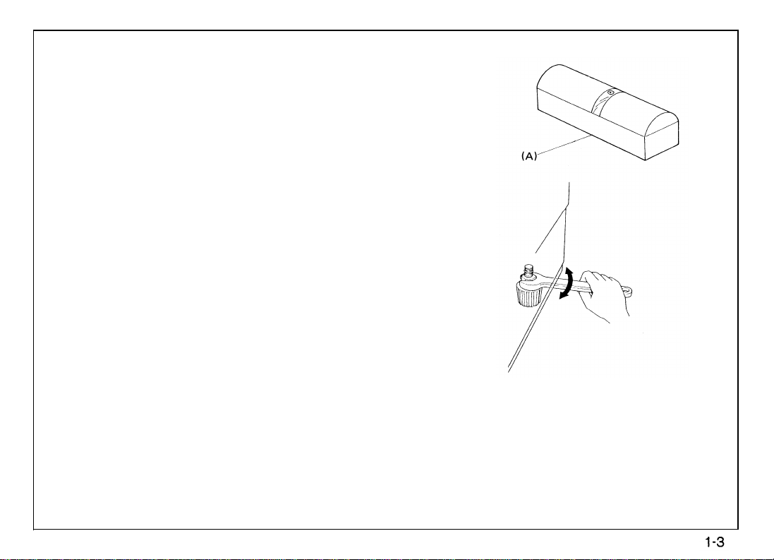
MACHINE LEVEL
1. Front to back: Within 5 mm (0.2”) of level
2. Right to left: Within 5 mm (0.2”) of level
31 March 1987
(Legs may be screwed up or down to level the machine. Set a carpenter’s level
the exposure glass.)
[A] on
Page 15
31 March 1987
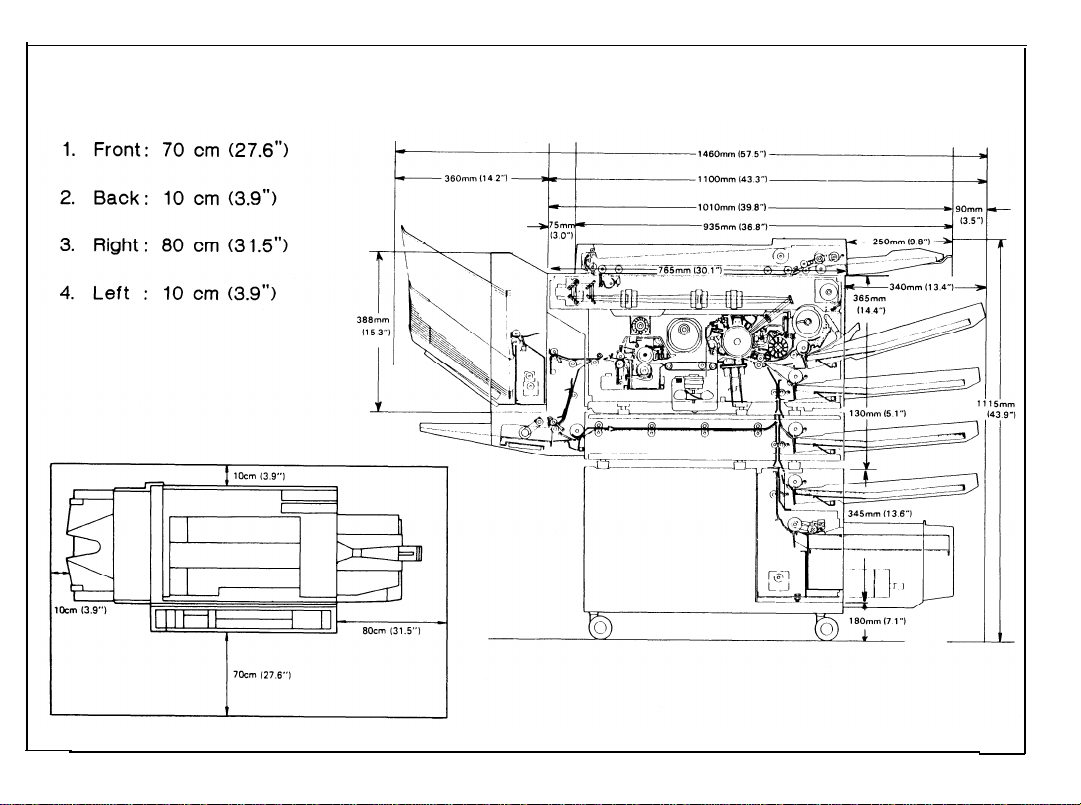
MINIMUM SPACE REQUIREMENTS
1-4
Page 16

POWER REQUIREMENTS
1.
Input voltage level
110V/60Hz : More than 15A
115V/60Hz : More than 15A
220V/50Hz : More than 7A
240V/50Hz : More than 7A
2.
Permissible voltage fluctuation: 10%
31 March 1987
3.
Permissible extension cord:
At least 300V, 30A capacity and less than 5 meters
(16.4 ft) long.
NOTES: a)
Be sure to ground the machine. (Do not connect the grounding wire to a gas
pipe.)
b)
Make sure the plug is firmly inserted in the outlet.
Avoid multi-wiring.
c)
Do not set anything on the power cord.
4.
1-5
Page 17
31 March 1987
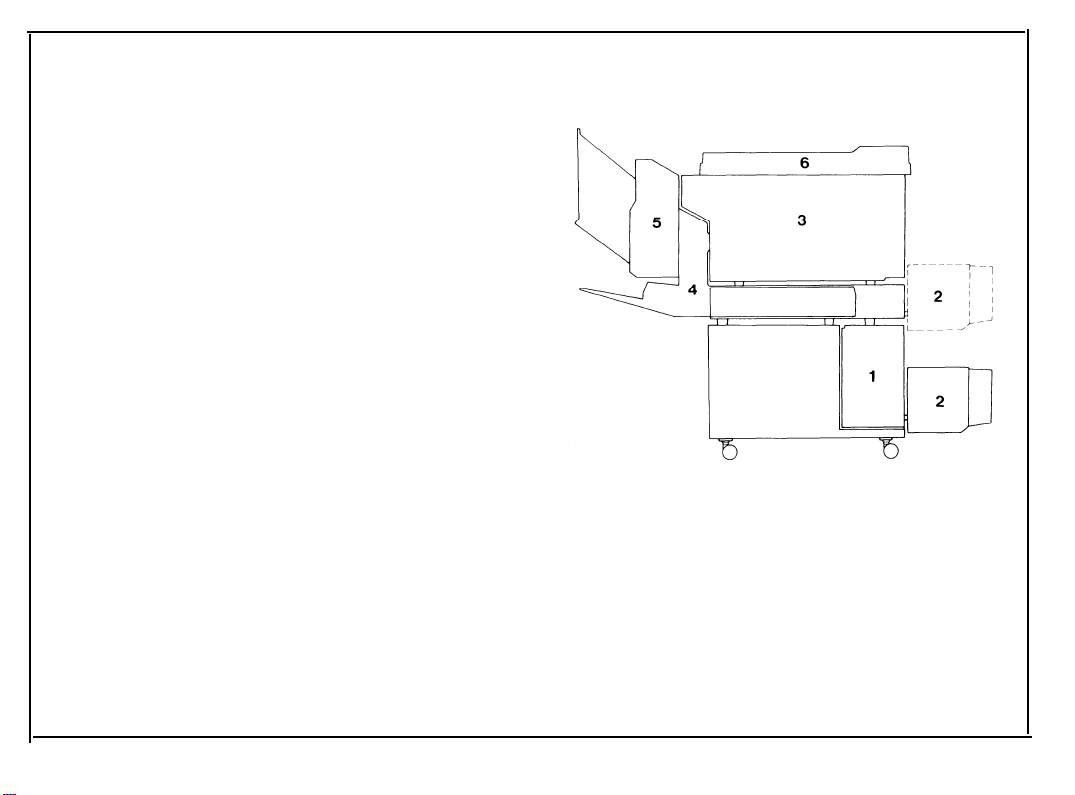
COMPONENT INSTALLATION PROCEDURE
1.
Paper Bank
2.
Large Capacity Tray
Copier
3.
Auto Duplex Unit
4.
Sorter
5.
Document Feeder
6.
The illustration to the right shows the relative order of installing the different components to the
base copier to obtain the system configuration
desired by the customer. This installation proce-
dure has been tailored to this illustration. The installation of components should start from the
lower numbered components and progress to
higher numbered components.
NOTE: When not instaIling the duplex unit or the
sorter save the duplex unit or sorter key
tops and key covers for future use.
1-6
Page 18
31 March 1987
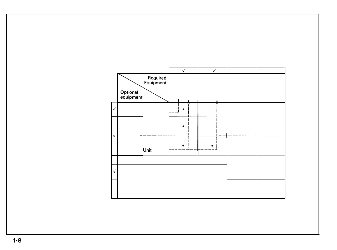
SYSTEM CONFIGURATION TABLE
Use this table to determine what extra equipment is required to install the optional equipment.
Duplex
Sorter
Duplex Unit
Large Capacity
Tray
Paper Bank
(4th and 5th
Cassette)
Unit
Without
Duplex
Unit
Interface
Board Adapter
(Note 2)
*
* *
*
Sorter
System Optional
Table Cassette
* *
(Note 1)
NOTE 1: All copiers have three cassettes as accessories.
NOTE 2: If the copier already has an ADF, sorter, or duplex unit installed, you do not need an in-
terface board.
1-7
Page 19
31 March 1987
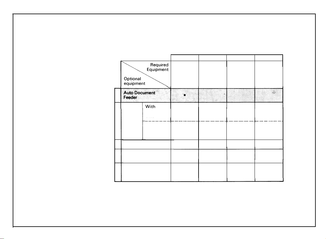
HOW TO USE:
As shown in the following example, check off each piece of optional equipment to be installed. For each checked item,
Check off each piece of required
the asterisks to the right show the required equipment.
equipment.
Auto Document
Feeder
With
Duplex
Sorter
Duplex Unit
Large Capacity
Tray
Paper Bank
(4th and 5th
Cassette)
Unit
Without
Duplex
Interface Sorter
Board Adapter
(Note 2)
*
System
Table Cassette
* *
Optional
(Note 1)
Page 20

31 March 1987
PAPER BANK INSTALLATION
ACCESSORY CHECK
Check the quantity and condition of the accessories in the box according to the following
list:
1. Installation procedure
(115V - English only, 220V - five languages)
2. New Equipment Condition Report
3. Envelope - NECR (115V only)
4. Expansion docking bracket
5. Expansion docking plate
6. Mylar paper guide
7. Expansion relay roller unit
8. Spring
9. Nylon wire clamp - large (10N)
10. Nylon wire clamp - small (4N)
11. Bank docking bracket
12. Pan head screw - M4 X 8
13. Pan head screw with washer - M4 X 8
14. Shoulder screw
15. Decal - Misfeed
16. Multilingual decals (220/240V only) 1 set
(115V - English only, 220V - five languages)
1
1
1
2
2
1
1
1
1
1
1
16
2
1
1
1-9
Page 21
31 March 1987
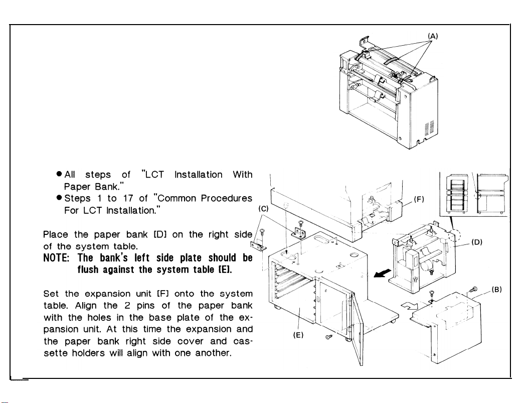
INSTALLATION PROCEDURE
1. Remove the strips of shipping tape [A].
2. Remove the right side of the system table
[B] (5 screws).
3. Install the front and rear expansion docking
brackets [C] on the system table as shown
(2 screws each).
Note: If an LCT is to be installed in the system,
first perform the following:
4.
5.
1-10
Page 22
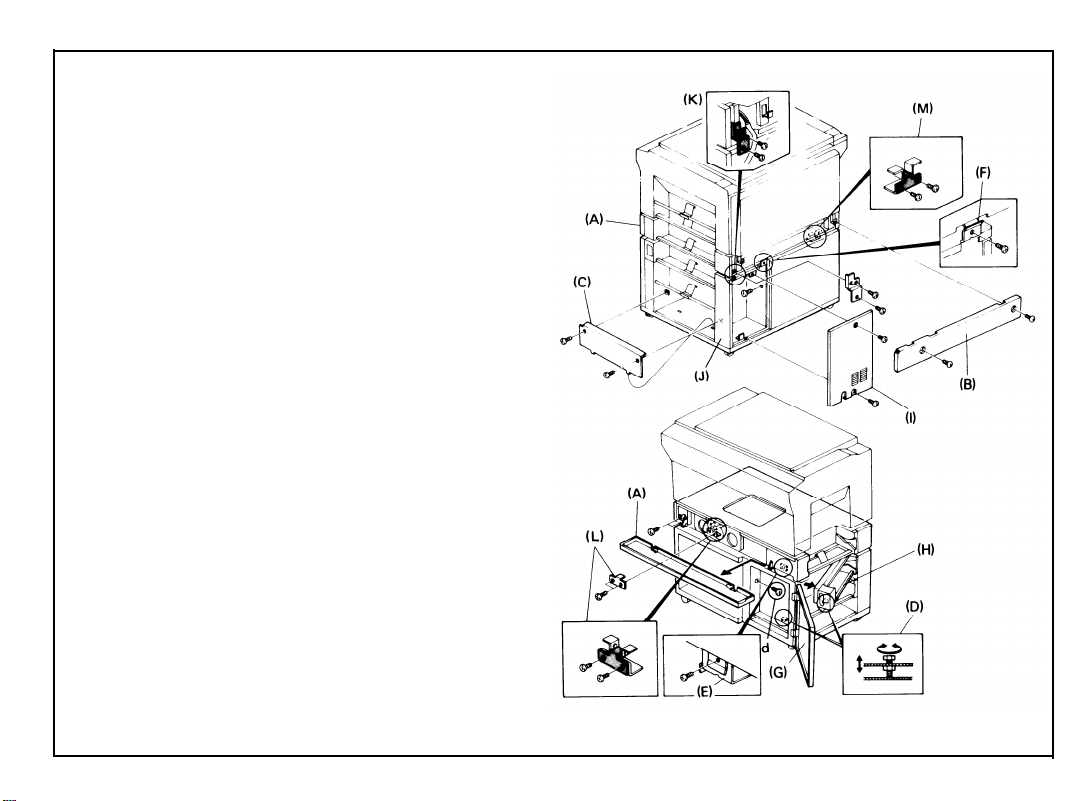
6. Remove the front [A] and rear [B] covers
from the expansion unit (2 screws each).
7. Adjust the height of the paper bank:
a. Remove the internal cover [C] from the
paper bank (2 screws).
b. Using the height adjusting bolts [D], raise
or lower the paper bank so that both the
front [E] and rear [F] screw holes of the
paper bank and expansion unit align.
c. Secure the paper bank to the expansion
unit (2 screws).
d. Open the system table front door [G],
swing out the 4th paper feed station [H],
and secure the paper bank to the front
side of the system table (1 screw).
e. Remove the bank rear cover [I] and the
bank rear right cover [J] (2
screws
each), then secure the bank to the rear
side of the system table (1 screw).
f. Install the bank docking bracket [K] (2
screws).
g. Install the internal cover to the paper
bank (2 screws).
8. Install the front [L] and rear [M] expansion
docking plates as shown (2 screws each).
31 March 1987
1-11
Page 23
31 March 1987
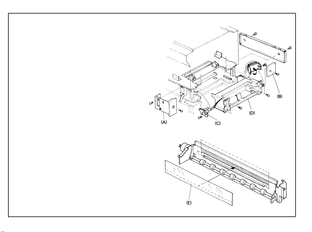
9.
Remove the front right [A] and rear right [B]
covers of the expansion unit (front - 2
screws, rear - 1 screw).
10.
Remove the right side safety switch assembly [C] (1 screw).
11.
Remove the copier rear cover (4 screws)
lower the PCB plate (2 screws), and disconnect the expansion interface harness from
the copier.
12.
Pull the 3rd feed unit out [D] (4 screws).
13.
System without duplex unit only:
Install the mylar paper guide [E] on the expansion relay roller unit.
1-12
Page 24
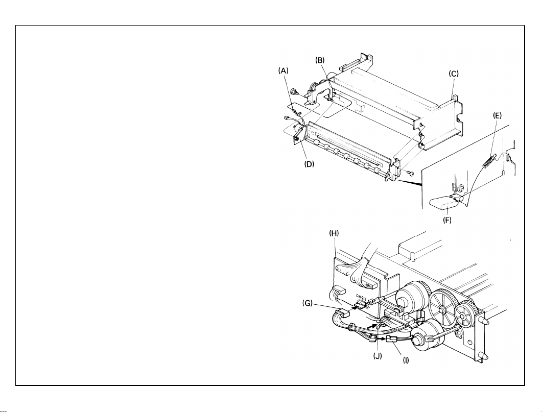
14.
While doing this step:
a. Run the expansion relay unit harness [A]
(except the clutch harness) through the
harness access hole [B] on the rear side of
the 3rd paper feed unit [C].
b. Set the front of the relay unit before set-
ting the hook on the rear.
Mount the expansion relay roller unit [D] on
the 3rd feed unit. (front: 1 screw and 2
hooks, rear: 1 shoulder screw and 1 hook).
Hook the spring [E] between the guide plate
15.
lever [F] and the 3rd feed unit mounting
bracket.
While doing this step, you must pass the ex-
16.
pansion interface harness and the safety
switch assembly around their respective expansion unit uprights.
Plug the 5P connector (red) [G], into CN912
of the 3rd paper feed PCB [H], connect the
other end to the expansion relay clutch [I],
and clamp the harnesses with the twist
clamp [J].
Reinstall the 3rd paper feed unit and the
17.
safety switch assembly (1 screw) in the expansion unit (4 screws).
31 March 1987
1-13
Page 25
31 March 1987
1-14
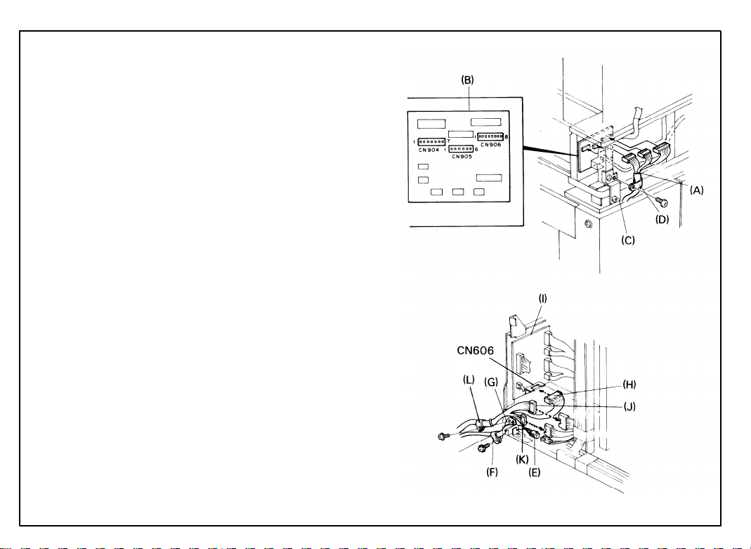
18.
Connect the bank interface harness [A] to
the 3rd paper feed PCB [B] as shown.
Clamp the bank interface harness to the
19.
bank docking bracket [C] with the large
nylon wire clamp [D] (1 screw with washer).
20.
a. Connect the ac paper bank harness [E]
to the copier and clamp the harness with
the small nylon wire clamp [F] on the left
image plate of the PCB plate [G] as
shown (1 screw with washer).
b. When doing this step, run the harness
from the left side of the PCB plate so
that the rear cover may close properly.
Connect the 9P expansion interface harness connector [H] to CN606 of the
paper feed PCB [I] and 2 free connectors (8P [J] and 6P [K]) to free connectors from the dc harness.
c. Fix the expansion interface harness to
the left hinge plate of the PCB plate with
the nylon wire clamp [L] (1 screw with
washer).
Page 26
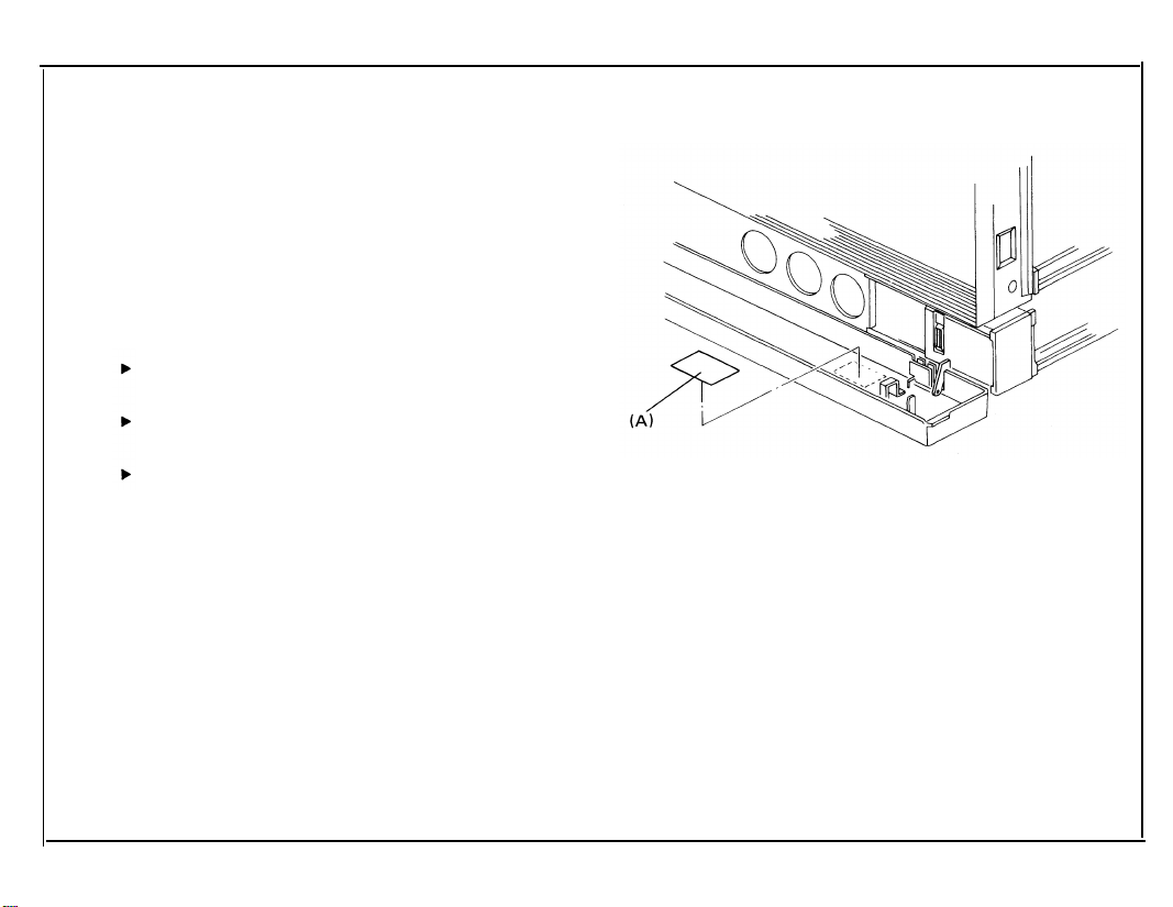
Stick the “Misfeed E” decal [A] on the front
21.
cover of the expansion unit as shown.
When reinstalling the expansion rear cover,
22.
place the bank ac harness inside the expansion unit.
Reinstall all covers except under the follow-
23.
ing conditions.:
If the LCT is to be installed, leave off
the bank rear cover.
If the duplex unit is to be installed, leave
off the expansion rear cover.
Leave off the copier rear cover if the du-
plex unit, DF, and/or sorter are to be installed.
24. Fill out the New Equipment Condition Report.
31 March 1987
1-15
Page 27

31 March 1987
COPIER INSTALLATION
ACCESSORY CHECK
Check the quantity and condition of the accessories in the box according to the following
list:
1. Installation procedure
(115V - English only, 220V - five languages)
2. New Equipment Condition Report
3. Envelope - NECR (115V only)
4. Cassette - large
5. Cassette - small
6. Receiving tray
7. Original holder
8. Editing sheet
9. Operating instructions
(115V - English only 220V - five languages)
10. Operating instruction cards
(115V - English only 220V - five languages)
11. Sort/Stack Key Cover
12. Sort/Stack Key Top
13. Duplex Key Cover
14. Duplex Key Top
15. Multilingual decals (220/240V only)
If not installing the duplex unit or sorter, save the duplex unit and sorter key tops and key
covers for future use.
1
1
1
1
2
1
1
1
1
1 set
1
1
1
1
1 set
1-25
Page 28
31 March 1987
INSTALLATION PROCEDURE
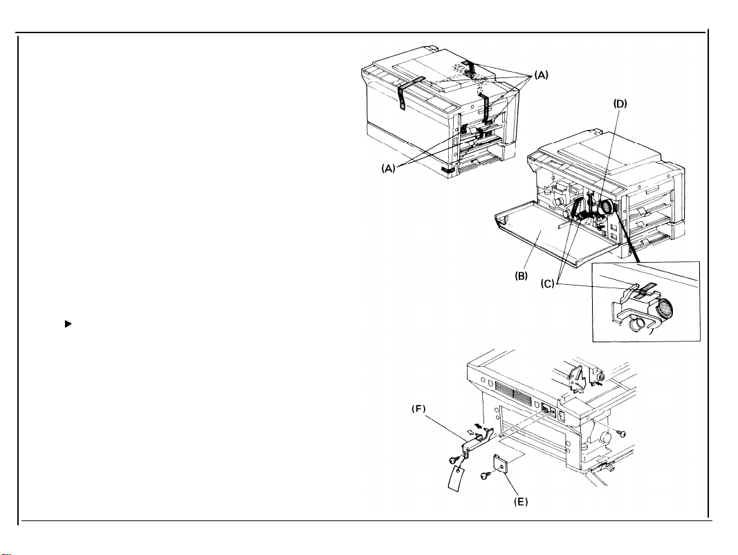
1.
Remove the shipping tape [A] from the copier as shown.
Open the copier front cover [B], remove the
2.
shipping tape [C] and the wedge [D] between the registration rollers as shown.
Remove the copier scanner lock plate
3.
cover [E] (1 screw).
Remove the copier scanner lock plate [F] (1
4.
screw).
Save the scanner lock plate for future
use.
Reinstall the copier scanner lock plate
5.
cover.
1-26
Page 29
6. Remove the fusing lock plate [A] (2
screws).
7. Use one of the screws removed in the previous step to secure the inner cover [B].
8. Pull out the fusing unit [C] to the lock position and remove the fusing unit cover [D] (2
screws).
9. Prime the oil supply pad [E] with silicon oil.
10. Fill the oil tank [F] with silicon oil.
11. Manually operate the oil pump lever [G] and
confirm proper operation and condition of
the silicon oil supply system.
12. Reassemble the fusing unit and return it to
its original position.
1-27
Page 30
31 March 1987
13. Raise the development lock lever [A] and
pull out the development unit [B]. Place the
unit on a clean sheet of paper.
14. Separate the toner tank [C] from the development unit [D] (2 screws).
15. Pour one bottle [E] of developer into the development unit while turning the knob [F]
counterclockwise to distribute the developer.
16. Remount the toner tank on the development
unit.
1-28
Page 31

17.
Swing the toner collection bottle cover [A]
to the left (1 screw) and unplug the toner
overflow sensor connector [B].
Remove the toner collection bottle [C].
18.
Lower the T/S corona unit [D].
19.
20.
Place a sheet of paper [E] over the T/S
corona unit.
21.
Remove the charge corona cover [F] (1
screw).
22.
Unplug the charge corona connectors
and remove the charge corona unit [H]
23.
Remove the quenching charge unit [I].
Remove the drum stay [J] (reverse thread-
24.
ed knob and 1 screw).
[G]
1-29
Page 32

31 March 1987
25. Remove the cleaning unit [A]. Dust the
cleaning blade [B] and brush [C] with setting powder (P/N 54429101).
26. Reinstall the cleaning unit.
27. Pull out the drum protective sleeve [D].
Save the drum protective sleeve for fu-
ture use when servicing the copier.
28. Reinstall the drum stay (1 knob and 1
screw), the quenching charge unit, and the
charge corona unit.
29. Reconnect the charge corona connectors
and reinstall the charge corona unit cover
(1 screw).
30. Remove the paper over the T/S corona unit
and return the T/S corona unit to its original
position.
1-30
Page 33

31. Reinstall the toner collection bottle [A] and
plug in the toner overflow sensor connector
[B].
32. Make sure that the hooks of the transport
plate [C] are positioned underneath the
bottle cover [D], then reinstall the toner collection bottle cover [E] (1 screw).
31 March 1987
CAUTION:
When installing the development unit
[F], be sure the development unit rail is
properly engaged with the guide rail in
the copier.
33. Reinstall the development unit.
1-31
Page 34

31 March 1987
1-32
34.
Install one toner cartridge [A].
Confirm that the toner cartridge gear is
properly engaged by attempting to
rotate the cartridge counterclockwise.
When the toner cartridge gear is properly engaged, the toner cartridge will not
rotate freely.
35.
240 volt areas only:
Remove the copier rear cover (3 screws),
disconnect the wire from the 220-volt terminal [B], and connect it to the 240-volt terminal [C] as shown. Reinstall the copier rear
cover.
Page 35

36.
Put five sheets of white paper (A3 or 11” x
17”) on the exposure glass.
37.
Lower the platen cover.
38.
Plug in the machine and turn on the main
switch.
39.
After pressing the Clear Modes Key, the
Clear/Stop Key, and the Recall/Enter Key in
that order, enter 10 using the Number Keys.
Press the Recall/Enter Key again.
After the warm up period is completed,
40.
press the Start key for drum conditioning.
After the machine stops, turn off the main
41.
switch.
Install the operating instruction cards [A]
42.
over the Dip switch cover as shown (twosided tape).
Install the original holder [B] on the platen
43.
cover as shown and install the receiving
tray [C].
Load paper into the cassette and check
44.
machine operation and copy quality.
Fill out the New Equipment Condition Report.
43.
31 March 1987
1-33
Page 36

CASSETTE MODIFICATION
1. Take off the cassette cover [A].
2. Remove the side fences [B] (1 screw each)
and the bottom plate [C].
3. Reposition the rear fence [D] in the desired
paper size position (1 screw).
Paper size positions are shown on the
inside of the cassette.
4. Reinstall the bottom plate.
5. Reinstall the side fences in the desired
paper size position.
6. Attach the proper paper size decals [E] on
the cassette at the positions shown.
7. Insert the actuator plate [F] in the slot on
the front of the cassette as shown.
1-34
Page 37

KEY COUNTER HOLDER INSTALLATION
Note: Ricoh, Hecon, and Hengstler key counters
are recommended for this copier.
1.
Remove the right front cover [A] (2
screws).
2.
Remove the cover plate [B] (2 screws).
3.
Pull out the 4P key counter connector [C]
through the key counter access hole and
remove the shorting plug [D].
4.
Connect the 4P connector on the key counter holder [E] to the key counter harness.
5.
Hold the fixing plate on the inside of the
key counter bracket [F] and insert the key
counter holder.
31 March 1987
1-35
Page 38

31 March 1987
1-36
6. Align the holes in the fixing plate with the
mounting holes of the key counter holder
and secure the key counter holder.
Note:
The fixing plate has three sets of
holes. Make sure to use the holes that
match the type of counter when installing.
7. Reinstall all covers.
Page 39

ACCESSORY COUNTER INSTALLATION
1.
Remove the front cover [A] (1 knob screw).
2.
Pull out the fusing unit [B] about half way.
3.
Remove the front inner cover [C] (5
screws); this cover should be removed from
the top first.
4.
Remove the accessory counter cover plate
[D] (2 screws).
5.
Push the accessory counter [E] into the
space provided until it locks.
6.
Connect the 2P connector [F] on the accessory counter to the counter harness [G].
7.
Reinstall all covers.
31 March 1987
1-37
Page 40

COLOR UNIT INSTALLATION
ACCESSORY CHECK
Check the quantity and the condition of the accessories in the box according to the following list:
31 March 1987
1.
Actuator -- Red
Actuator -- Blue
2.
Actuator -- Green
3.
Screw
4.
5.
Color Decal Sheet
Note: The color development unit should be installed after
This procedure should be done when the color developer
-- M3 x 4
1
1
1
1
1
drum conditioning is finished.
is replaced.
1-75
Page 41

31 March 1987
INSTALLATION PROCEDURE
1.
Install the appropriate color actuator [A]
on the color development unit.
Stick the appropriate decal [B] on the de-
2.
velopment unit handle.
3.
Separate the toner tank [C] from the de-
velopment unit [D] (2 screws).
Pour one bottle of color developer [E]
4.
into the development unit while turning
the knob [F] counterclockwise to distribute the developer.
1-76
Page 42

Steps 5 through 16 should also be done when
color developer is replaced.
5.
Remount the toner tank onto the develop-
ment unit.
Making sure that the color development
6.
unit is properly engaged with the unit
guide rail of the copier, install the color
development unit [A].
7.
Install a color toner cartridge [B].
8.
Remove the DIP switch cover [C] on the
left side of the operation panel (1 screw)
and turn on DIP SW5 [D].
9.
Plug in the machine and turn on the main
switch. Confirm that the color toner indicator is displayed on the operation panel.
Press the Program key. “20” should be
10.
displayed in the Copy Counter.
31 March 1987
11.
Put five sheets of white paper (A3 or
11” x 17”) on the exposure glass.
1-77
Page 43

31 March 1987
12.
Lower the platen cover.
13.
After the warm up period is completed,
press the Start key.
14.
After the machine stops, press the appropriate Number key according to the following list:
Red toner: 7
Green toner: 8
Blue toner: 9
15.
Turn off the main switch and the DIP
switch.
16.
Reinstall the DIP switch cover (1 screw).
1-78
Page 44

PREPARATION FOR TRANSPORTING THE COPIER
SHORT HAUL TRANSPORTATION
Before moving the copier from its place of installation, be sure to prepare it for transporta-
tion as follows:
31 March 1987
CAUTION:
1.
2.
3.
4.
The copier may be seriously damaged if it is moved without proper
preparation.
the drum protective sleeve [A].
Insert
Re-install the development unit.
Re-install the drum stay and charge
corona unit.
Secure the following items with tape:
Manual feed table
Platen cover or document feeder
The power supply cord (roll up first)
Expansion front cover
System table front door
1-79
Page 45

31 March 1987
5.
Remove the sorter to prevent damage to
the bins.
6.
Remove the
7.
Remove the
8.
Remove the
ment feeder.
Remove
9.
3rd feed
duplex receiving tray.
cassettes.
original table from the docu-
the
LCT if it is installed in the
station.
1-80
Page 46

LONG HAUL TRANSPORTATION BY VEHICLE
If the machine is to be transported by vehicle,
do the following
pleted the above
steps after you have comshort haul procedure.
31 March 1987
1. Remove the
developer from the develop-
ment unit.
2. Place a wedge between the registration
rollers.
3. Remove the sorter and secure the follow-
ing items with tape.
top cover
jam clearing tray
bins--tape the right and left edges of
the spacers together.
4. Remove the scanner lock plate cover [A]
and install the scanner lock plate [B].
NOTE: Confirm that the scanner is at the
home position.
1-81
Page 47

5.
Secure the following items with tape:
T/S corona release lever to the drum
stay knob
Transport plate to the toner collec-
tion bottle cover
Toner shield glass
1st and 2nd feed guide plates
6.
Remove the LCT if it is installed in the
5th feed station.
7.
Secure the LCT covers and power supply
cord with tape.
8.
Separate the system into the two units
as follows:
Paper Bank and System Table
Copier, duplex unit and/or document
feeder
9.
Tape the bank interface harness and ac
harnesses to the top of the bank.
1-82
Page 48

SECTION II
Page 49

II.
SERVICE TABLES
PM Table . . . . . . . . . . . . . . . . . . . . . . . . . . . . . . . . . . . . . . . . . . . . . . . . . . . . . . . . . . . . . . . . . . . . . 2-1
Service Program Mode Operation . . . . . . . . . . . . . . . . . . . . . . . . . . . . . . . . . . . . . . . . . . . . . . . . . 2-6
Service Remarks . . . . . . . . . . . . . . . . . . . . . . . . . . . . . . . . . . . . . . . . . . . . . . . . . . . . . . . . . . . . . . . 2-32
Page 50

PM TABLE
C: Clean R: Replace L: Lubricate A: Add I: Inspect
31 March ’87
ITEM
OPTICS
1. Mirrors, lens, reflectors, toner
shield glass
2. Exposure glass
3. Platen cover sheet
4. Scanner guide rod
and plate
5. Guide rod felt
6. APS sensor
7. ADS sensor
PAPER FEED
8. Paper feed roller
9. Friction pad
10. Paper feed guide
plate
11. Registration sensor
EM
80K 160K
C
C C
C C C C
C C C C
L L L L
L
C
C C
C C
C
R R R R
C
R R R R
C C
C C C C
240K 320K
L
C C C
C
L
C
C C
NOTES
C
C
C
L
C
Alcohol or water (silicone
cloth)
Alcohol or water
Alcohol or water (replace if
necessary)
Launa oil or equivalent
Launa oil or equivalent
(if necessary)
Dry cloth
Dry cloth
Water
Water
Blower brush
2-1
Page 51

31 march ’87
C: Clean R: Replace L: Lubricate A: Add I: Inspect
ITEM
12. Cassette bottom
plate pad
13. Paper feed sensor
AROUND DRUM
14. Corona wires
15. Wire cleaner
16. End blocks and casing
17. Transfer guide plate
18. PTL filter
19. QL filter
20. ID sensor
21. Erase lamp unit
EM
80K 160K
C
240K 320K
C
C
C C C
C R R R R
R R R R
C C C
C
C
C
C
C
C C C
C
C C
C C C
C
C
C
C
C C
C
C
NOTES
C
C
Alcohol or water
Blower brush
Dry cloth
Dry cloth
Dry cloth
C
Dry cloth, discharge before
installation.
C
Dry cloth, discharge before
installation.
Blower brush
C
Dry cloth
2-2
Page 52

C: Clean R: Replace L: Lubricate A: Add I: Inspect
31 March ’87
ITEM
CLEANING UNIT
22. Cleaning blade
23. Cleaning seal
24. Cleaning brush
25. Bias roller blade
26. Bias roller
27. Cleaning unit
28. Pick-off pawls
29. Used toner bottle
DEVELOPMENT UNIT
30. Developer
31. Upper brush seal
32. Side seals
33. Development unit guide
34. Toner supply clutch
35. Filter casing
EM
C
C
80K
R
C
R
R
C
C
C
C
R
C
C
C
C
160K
R
C
R
R
C
C
C
C
R
C
C
C
L
C
240K
R
C
R
R
C
C
C
C
R
C
C
C
C
320K
R
C
R
R
C
C
C
C
R
C
C
C
L
C
NOTES
Dust with setting powder
Replace if necessary
Dust with setting powder
Replace if necessary
Empty of used toner
If necessary
Mobil Temp 78
2-3
Page 53

31 march ’87
C: Clean R: Replace L: Lubricate A: Add I: Inspect
ITEM
FUSING UNIT
36. Hot roller
37. Pressure roller
38. Stripper pawls
39. Oil supply pad
40. Oil blade
41. Fusing entrance and
exit guides
42. Oil sump
43. Oil tank
OTHERS
44. Development drive
chain
45. Main drive chain
46. Transport belt
47. Bushings
48. Fusing drive gear
49. Development sleeve
gear
50. Resin gear
EM
80K 160K
C R C R
C
R
C
R
R R R R
C
R
C C C
C
C C C
C C C C
L L
L L
C
L
L L
L
L
240K 320K
C
R
C
R
C
R
C
C
C
L
L
L
NOTES
If necessary
Replace if necessary
Prime with silicone oil
Prime with silicone oil
Suitable solvent
Remove paper clay
with pipette
Spindle oil
Mobil Temp 78
Alcohol or water
Spindle oil
Mobil Temp 78
Silicone G-40M
Silicone G-40M
2-4
Page 54

C: Clean R: Replace L: Lubricate A: Add I: Inspect
31 March ’87
ITEM
DUPLEX UNIT
51. Duplex spring clutch
52. Paper feed roller
53. Friction pad
54. O-ring
55. Positioning roller
DOCUMENT FEEDER
56. Belt
57. Pick-up roller
58. Feed roller
59. Friction roller
LARGE CAPACITY TRAY
60. Pick-up roller
EM
C
C
C
C
C
80K
C
C
C
C
160KL240K
R
R
R
C
C
C
C
C
320K
L
C
C
C
C
R
NOTES
Mobil Temp 78
Dry cloth
Belt cleaner, replace if
necessary
Water, replace if necessary
Water, replace if necessary
Water, replace if necessary
Water
2-5
Page 55

31 march ’87
SERVICE PROGRAM MODE OPERATION
The service program mode is used to (1) check electrical data and (2) change modes or
adjustment values. The factory settings are stored in ROM; other settings are stored in
permanent (battery maintained) RAM.
1.
Data Check Mode
1.
Remove the DIP switch cover on
Copy Counter will start blinking.
2.
Enter the number of the desired
Service Program Mode table.
3.
Press the Enter (#) key.
4.
The appropriate data will be displayed in the Magnification indicator.
5.
After you have finished with the service program mode, turn off DIP SW No. 8.
the operation panel and turn on DIP SW 201-8. The
SP Mode using the numeral keys according to the
2-6
Page 56

2. Data Change Mode
1. Follow steps 1-3 of the preceding procedure.
2. Factory setting values or mode will be displayed in the Magnification indicator (threedigit indicator). (If the data values are not to be changed, turn off DIP SW 201-8.)
3. Enter the desired value or mode using the numeral keys according to the Service
Program Mode table.
4. Turn off DIP SW 201-8.
• The following procedure can also be used to access program numbers 10, 11, 90,
91, and 92 instead of using DIP SW 201-8.
1. Press the Mode Clear key.
2. Press the Clear/Stop key.
3. Press the Enter key; at this time the Copy Counter should blink.
4. Enter the desired number using the numeral keys.
5. Press the Enter key.
• Service program mode is cleared by pressing the Clear Modes key.
2-7
Page 57

31 march ’87
3. Service Program Mode Table
Mode No.
5 Exposure Lamp Free run with expo-
OFF Free Run sure lamp OFF
6 Jam Detection
OFF
7 Charge Wire
Cleaner
8 Input Check
9 Exposure Lamp
output regulator output.
Function
Copies are made
without jam detection.
Charge wire cleaner
motor operation.
Displays the input
from sensors.
Displays lamp
Data Factory Comments
Setting
The total counter
advances while
copying.
The motor starts
when Enter key is
pressed. Stops after
1 cycle (about 60 s).
For data, see the
input check table.
Input #1 then press
the Enter key. The
lamp stays on 10 s.
2-8
Page 58

31 March ’87
Mode No.
Function
Data
Factory Comments
Setting
10 Drum Condi- Used to condition a Enter 10 via the
tioning new drum.
number keys. 100 will
appear in the copy
counter. Press Start
to activate.
For 50 copies, lamp is
on. Then lamp OFF
until Vsp > 0.4 V.
Then, lamp on for
rest of cycle. Press
C/S to stop.
11 All Indicators Turns on all the in-
ON
dicators on the operation panel.
13 Destination Shows the market
Code
the machine is
intended for.
D = Japan
A = USA
C = Canada
E = Europe
F = Taiwan
2-9
Page 59

31 march ’87
Mode No.
Function
15 Auto Reset Selects auto reset
Time
16 Count Up/Down
of 1 or 3 minutes.
Selects count up
or count down.
17 Auto Cassette Selects auto-
Shift cassette shift
mode
18 Beeper
Turns beeper ON
or OFF
19 Image Density Selects the pri-
Mode
ority of image
density control
when the main
switch is turned on.
20 Feed Station Selects feed station
Priority priority at power on. 1: 1st
Data Factory Comments
Setting
0: 1 min.
0
1: 3 min.
2: None
0: UP
0
1: DOWN
0: ON
1: OFF
0
Copier automatically
shifts to another
cassette holding same
size paper when paper
runs out.
0: ON
0
1: OFF
0: ADS
0
1: Manual
0: LCT
0
2-10
Page 60

31 March ’87
Mode No.
21 APS Priority
22 Auto Mode
Reset
23 Free Size
28 Auto Sort Mode
29 Fusing Unit
Idle
Function
Selects APS or manual
Sets the auto-reset
time.
Enables originals of
various sizes to be
fed from the same
stack.
Sort mode is automatically selected
when more than 2 originals are set on the
DF original table and
the entered quantity
is greater than 2.
Selects fusing unit
idling mode.
Data Factory Comments
Setting
0: APS
0
1: Manual
0: 4 s
1: 60 s
0: Normal
0
Timer starts from
original feed out.
0
1: Free
0: Normal
1: Sort
Sorter and DF must
0
be installed on the
machine.
0: OFF
0
Idles for 15 s.
1: ON
30 Toner Supply
Mode
Selects toner supply
system.
0: Detect
1: Fixed
0
2-11
Page 61

31 march ’87
Mode No.
31 Toner Supply
Amount (Detect
Mode)
32 Toner Supply
Amount (Fixed
Mode)
33 ID Sensor
Bias (Black
Toner)
35 Toner Supply
Function
Determines how much
toner is supplied in
detect mode.
Determines how much
toner is supplied in
fixed mode.
Sets the bias voltage applied to the
bias roller when
sensing image
density.
ID sensor check is
performed every 5
copies. Changes
toner end level
from 0.75 V to
0.7 V.
Data Factory
Setting
0: 30%
0
1: 15%
2: 45%
3: 60%
0: 7%
0
1: 3.5%
2: 10.5%
3: 14%
0: 500
0
1: 440
2: 470
3: 530
0: Normal
0
1: ON
Comments
500 V = normal
440 V = lightest
470 V = light
530 V = dark
2-12
Page 62

31 March ’87
Mode No.
36 Margin
Adjustment
37 Lead Edge Sep- Sets the Iength of
aration Corona
Timing
Function
Data
Selects the preset 0: 5 mm
margin adjustment 1: 10 mm
value.
2: 15 mm
0: 10 mm
time that the lead 1: 15 mm
edge separation corona
is applied.
38 Erase margin Sets the width of 0: 10 mm
the erase margin.
1: 5 mm
2: 15 mm
3: 20 mm
39 Charge Wire Sets charge wire
Cleaner
cleaner operation to
0: ON
1: OFF
ON or OFF.
41 Lead Edge Adjusts the lead 0 - 15
Erase Margin edge margin.
Adjustment
Factory Comments
Setting
0
0
Use when separation
problems occur.
0
0
8
1 mm per step
+7 mm to -8 mm
42 Registration Adjusts registration.
Adjustment
0 - 15
8
1 mm per step
+7 mm to -8 mm
2-13
Page 63

31 march ’87
Mode No.
Function
Data Factory Comments
43 Vertical Adjusts magnification 0 - 15
Magnification
Adjustment
in the paper travel
direction.
44 Horizontal Adjusts magnification 0 - 15
Magnification
perpendicular to the
Adjustment direction of paper
travel.
46 Size Detec-
tion Error
Corrects size
detection.
0 - 15
Correction
49 Fusing Tempera- Adjusts fusing temp.
ture Adjustment
50 Length Detec-
tion Check
Displays the length
detected by the size
0: Normal
1: Low
detection circuit.
Setting
8
8
8
0
0.2% per step
+1.4% to -1.6%
0.2% per step
+1.4% to -1.6%
1 mm per step
+7 mm to -8 mm
185°
175°
Press Start key
to display. Do not
repeat more than 10
times to avoid overheating the fiber
optic cables.
2-14
Page 64

31 March ’87
Mode No.
51 Exposure Lamp
Voltage Check
52 Fusing Temper-
ature
53 Drum Tempera-
ture
54 Vsg Adjustment
55 Vsg/Vsp
Check
56 ADS Reference
Voltage
Function
Displays exposure
lamp voltage.
Displays the fusing
temperature.
Displays the drum
temperature.
Turns on ID sensor
LED.
Displays Vsg and Vsp.
Sets ADS reference
voltage for standard
originals. Press Print
to start and C/S
to stop.
Data
Factory
Setting
Comments
Adjust Vsg with VR
on the ID sensor board
LED turns on 10 s
(no drum rotation).
Average value of
10 copies.
Machine starts free
run.
2-15
Page 65

31 march ’87
Mode No.
57 ADS Voltage
(Non-standard
Original)
58 APS Sensor
Adjustment
59 Bias Voltage
Function
Checks ADS Voltage
for non-standard
Originals. Press
Start key to turn
on. Press C/S to
stop.
Adjusts the APS
sensor voltage with
standard original.
Press Start key to
turn on. After pressing # key, press 0
to set length voltage or press 1 to
set width voltage.
Press C/S to stop.
Displays bias voltage.
Press Start to turn on.
Press C/S to stop.
Data
Factory
Setting
Comments
Machine starts free
run.
Machine starts free
run. APS voltage is
adjusted.
Without temperature
compensation.
2-16
Page 66

31 March ’87
Mode No.
60 Toner Density
Recovery
70 Color Toner
Supply Amount
(Fixed Mode)
73 Color Toner
Copy Count
Function
After the Start key
is pressed, the
toner supply clutch
turns on and free run
starts. Free run stops
and constant supply
is reset when Vsp
becomes < 0.5 V.
Selects the color
toner supply ratio.
Shows the number
of color copies
made.
Data
0: 14%
1: 7%
2: 21%
3: 28%
4: 35%
5: 42%
6: 49%
7: 56%
0: Red
1: Green
2: Blue
Factory
Setting
0
Comments
Use this mode to
bring a Iow toner
condition back to
normal. Use only
with black toner.
During this period,
Vsp is displayed. Press
0 to display Vsg.
Multiply number
by 100. Example:
24 = 2400 sheets.
Cannot be reset
unless memory is
cleared.
2-17
Page 67

31 march ’87
Mode No.
Function
74 Door Open Sets the copier to
Location
Indicator
show the locations
of open doors using
the Jam indicator.
75 ID Sensor Sets the bias volt-
Bias (Color
Toner)
age applied to the
bias roller when
sensing image
density.
76 Sorter Bin
Capacity
77 Odd Number
Duplex Copy
Sets the stack mode
quantity limit.
Sets the copier to
eject the final copy
if an odd number of
originals is copied.
(When copying single
sided originals
only.)
Data Factory Comments
Setting
0: OFF
1: ON
0: 620
1: 590
0
Not effective for
the front door.
0
620 V = normal
590 V = lighter
2: 650 650 V = darker
Limit is determined
0: No limit
1: Limit
0: ON
1: OFF
0
by paper size.
When on, the final
0
sheet is fed out; when
off, it stays in the
duplex tray.
2-18
Page 68

31 March ’87
Mode No.
79 Maximum Repro-
duction Ratio
86 PM Counter
87 PM Copy
Count
88 PM Counter
Check
89 PM Counter
Reset
90 User Code
Mode
Function
Sets the maximum
reproduction ratio.
Turns on the PM
counter.
Sets the interval
of the PM counter.
Displays contents
of the PM counter.
Resets the PM
counter.
Selects user code
mode. (Key counter
shorting connector
must be removed.)
Data
0: 155%
1: 200%
0: OFF
1: ON
0: 80 k
1: 60 k
2: 100 k
0: OFF
1: ON
Factory
Setting
0
0
0
0
Comments
For PB machines, 0 is
ON and 1 is OFF.
When the PM count is
exceeded the Service
Call and Key Counter
indicators blink.
Use after performing
PM.
If on, must enter a
code to copy. See
user code table.
Reset after 60s or if
C/S and CIear Modes
pressed together.
2-19
Page 69

31 march ’87
Mode No.
Function
91 User Code Displays the contents
Counter Check
of each user counter.
Use + and - keys to
select user code (lower
two digits of user
code displayed in copy
counter). First 3 digits
of copy count are
displayed in Magnification indicator.
Press “.”
to display
second 3 digits.
92 User Code
Counter Reset
Resets user counters.
Select the user code
counter using + and -
keys. To reset press
1 then #.
Data
Factory
Setting
Comments
User counters count
from 0 to 999999
(endless count).
2-20
Page 70

31 March ’87
Mode No.
93 Maximum Copy
Function
Limits the maximum
Quantity copy quantity that
can be entered.
97 Clear Service
& Jam Count
98 Clear
Counters
Clears the service
call and jam counters. must be on.
Clears the following Cleared at factory.
counters:
- counters 100 to 139 must be on.
- user program
- PM counter
- User code counter
99 Clear All
Memory
Clears all counters
and returns all modes
to factory settings.
Data Factory Comments
Setting
0
The indicator blinks
and the limit quantity is displayed.
If you enter 0, the
max is 999.
Otherwise, max is
number entered.
DIP SW 201-7
DIP SW 201-7
Test pin 101 and
102 shorted.
DIP SW 201-7
must be on.
2-21
Page 71

31 march ’87
Mode No.
100 Main Motor
ON Time
101 Total Copies
102 Duplex Copies
Function
Displays the total
(accumulated) time
that the main motor
has operated.
Displays the total
number of copies.
Displays the total
number of duplex
copies made.
Data
Factory
Setting
Comments
Time in hours.
The first three digits
are shown in the Magnification indicator.
Press “.”
to display
the second 3 digits.
The first three digits
are shown in the Magnification indicator.
Press “.”
to display
the second 3 digits.
2-22
Page 72

31 March ’87
Mode No.
103 DF Copies
104 Sort Copies
105 Paper Bank
Copies
106 LCT Copies
Function
Displays the total
number of copies
made using the DF.
Displays the total
number of copies
made using the
sorter.
Displays the total
number of sheets
fed from the paper
bank unit.
Displays the total
number of sheets
fed from the LCT.
Data Factory Comments
Setting
The first three digits
are shown in the Magnification indicator.
Press “.” to display
the second 3 digits.
The first three digits
are shown in the Magnification indicator.
Press “.” to display
the second 3 digits.
The first three digits
are shown in the Magnification indicator.
Press “.”
to display
the second 3 digits.
The first three digits
are shown in the Magnification indicator.
Press “.” to display
the second 3 digits.
2-23
Page 73

31 march ’87
Mode No.
108 A3/11 x 17
Copies
109 A4/8-1/2 x 11
Copies
111 Reduction
Copies
112 Enlarged
Copies
Function
Displays the total
number of A3 or
11 x 17 copies.
Displays the total
number of A4 or
8-1/2 x 11 copies.
Displays the total
number of reduction
copies.
Displays the total
number of enlarged
copies.
Data
Comments
The first three digits
are shown in the Magnification indicator.
Press “.” to display
the second 3 digits.
The first three digits
are shown in the Msgnification indicator.
Press “.”
to display
the second 3 digits.
The first three digits
are shown in the Magnification indicator.
Press “.”
to display
the second 3 digits.
The first three digits
are shown in the Magnification indicator.
Press “.”
to display
the second 3 digits.
2-24
Page 74

31 March ’87
Mode No.
Function
Data Factory Comments
Setting
114 Originals Displays the total The first three digits
Copied
number of originals
copied.
are shown in the Magnification indicator.
Press “.” to display
the second 3 digits.
115 Originals Displays the total
Copied Using
DF
number of originals
copied using the DF.
The first three digits
are shown in the Magnification indicator.
Press “.”
to display
the second 3 digits.
120 Total Service Displays the total
Calls
number times that the
Service Call indicator
has turned on.
The first three digits
are shown in the Magnification indicator.
Press “.” to display
the second 3 digits.
121 Service Calls Displays the total
for Optics
number “Optics”
service calls.
The first three digits
are shown in the Magnification indicator.
Press “.” to display
the second 3 digits.
2-25
Page 75

31 march ’87
Mode No.
122 Service Calls
for Exposure
123 Service Calls
for Drive
124 Service Calls
for Fusing
Function
Displays the total
number of “Exposure”
service calls.
Displays the total
number of “Drive”
service calls.
Displays the total
number of “Fusing”
service calls.
Data Factory
Setting
Comments
The first three digits
are shown in the Magnification indicator.
Press “.”
to display
the second 3 digits.
The first three digits
are shown in the Magnification indicator.
Press “.”
to display
the second 3 digits.
This service call can
result from the pulse
generator or corona
wire cleaner sensor.
The first three digits
are shown in the Magnification indicator.
Press “.”
to display
the second 3 digits.
2-26
Page 76

31 March ’87
Mode No.
125 Service Calls
for Interface
Communication
130 Paper Jams
131 Feed Jams
132 Fusing Jams
Function
Displays the total
number of “Interface
Communication” service
calls.
Displays the total
number of paper jams.
Displays the total
number of entrance
area paper jams.
Displays the total
number of jams at the
fusing unit.
Data Factory Comments
Setting
The first three digits
are shown in the Magnification indicator.
Press “.” to display
the second 3 digits.
The first three digits
are shown in the Magnification indicator.
Press “.” to display
the second 3 digits.
The first three digits
are shown in the Magnification indicator.
Press “.” to display
the second 3 digits.
The first three digits
are shown in the Magnification indicator.
Press “.” to display
the second 3 digits.
2-27
Page 77

31 march ’87
Mode No.
134 Duplex Jams
136 Exit Jams
137 Paper Bank
Jams
138 Sorter Jams
Function
Displays the total
number of jams in the
duplex area.
Displays the total
number of jams in the
exit area.
Displays the total
number of paper bank
jams.
Displays the total
number of sorter
jams.
Data
Factory
Setting
Comments
The first three digits
are shown in the Magnification indicator.
Press “.”
to display
the second 3 digits.
The first three digits
are shown in the Magnification indicator.
Press “.”
to display
the second 3 digits.
The first three digits
are shown in the Magnification indicator.
Press “.”
to display
the second 3 digits.
The first three digits
are shown in the Mag-
nification indicator.
Press “.”
to display
the second 3 digits.
2-28
Page 78

31 March ’87
Mode No.
Function
139 DF Jams Displays the total
number of DF jams.
Data
Factory Comments
Setting
The first three digits
are shown in the Magnification indicator.
Press
“.” to display
the second 3 digits.
2-29
Page 79

31 march ’87
Input Check Table
No.
1
3
4
5
6
7
11
15
16
17
18
20
21
22
25
26
27
28
29
Item
Registration Sensor
Exit Sensor
Relay Roller Sensor
Relay Roller Sensor
Relay Roller Sensor
Duplex Exit Sensor
Duplex Tray Sensor
Sorter Inlet Sensor
Sorter Bin Sensor
Sorter Home Position Sensor
Sorter Cover Switch
Toner End Sensor (Color)
Key Counter Noise Prevention Switch 0
Charge Corona Wire Cleaner Sensor 0
Paper Bank Installed
Large Capacity Tray
Duplex Unit Installed
Midi Sorter Installed
Mini Sorter Installed
#3
#4
#5
Installed
Normal Mode
0
0
0
0
0
0
0
0
1
0
1
1
1
1
1
1
1
2-30
Page 80

USER CODES
There are 20 user codes as follows:
31 March ’87
2
3
4
5
6
7
8
9
10
1
1101
1202
1303
1404
1505
1606
1707
1808
1909
2010
11
12
13
14
15
16
17
18
19
20
2111
2212
2313
2414
2515
2616
2717
2818
2919
3020
2-31
Page 81

31 march ’87
SERVICE REMARKS
General Caution:
Keep hands away from mechanical drive components when the copier is warming up. This is
to avoid possible injury when the copier starts idling at the end of warm up.
NOTE:
The following two items are the only service remarks that are unique to this copier. For
other service remarks, refer to the base machine’s manual (F9 manual).
1. When the main board is removed from the PCB plate, do not put it on a conductive
surface. (This is to avoid discharging the battery of the user program memory.)
2. When installing a new RAM board on the main board, clear its RAM as follows:
a. Make sure that the main switch is off.
b. Fix the new main board to the PCB plate and plug in all the connectors.
c. Connect test pins TP101 and TP102 with a jumper wire.
d. Turn on the main switch.
e. Turn on DIP switch 201-7 and 201-8.
f. Press 9, 9, #, and 1 in that order.
g. Turn off the main switch and remove the jumper wire.
3. Make sure the main switch is off when you install a previously used RAM board on a
new main board.
2-32
Page 82

SECTION Ill
REPLACEMENT AND
ADJUSTMENT
Page 83

III. REPLACEMENT AND ADJUSTMENT
Page 84

OPTICS
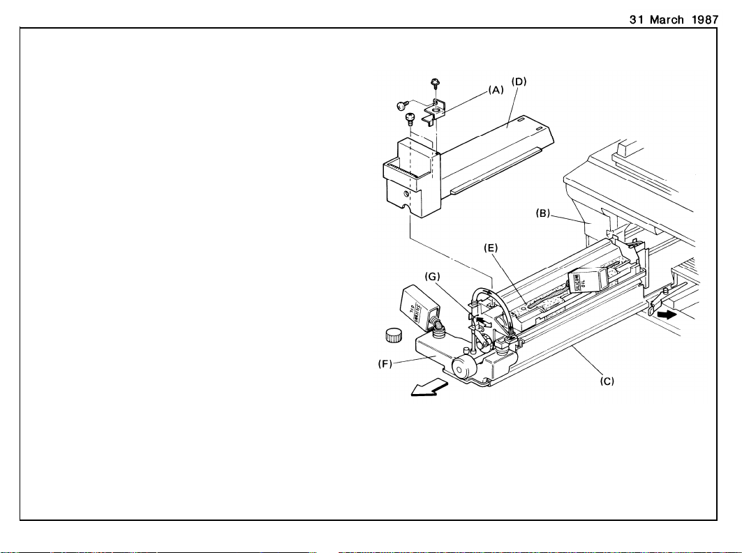
1.
FIBER OPTICS CABLE REPLACEMENT
1.
Remove the front cover [A] (1 knob screw)
and pull the fusing unit [B] about halfway
out.
2.
Remove the front inner cover [C] (5
screws).
Remove the power relay bracket [D] (1
3.
screw).
Disconnect the exposure lamp harness [E]
4.
(2p white connector).
Take off the left scale (2 short screws).
5.
Remove the exposure glass.
6.
31 March ’87
3-1
Page 85

31 March ’87
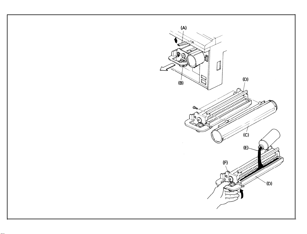
7.
Remove the front terminal cover [A] (1
screw).
8.
Unhook the fiber optics cable [B] from the
reflector cover [C] and remove the reflector
cover (2 screws).
9.
Remove the leads to the exposure lamp
terminals [D].
10.
Remove the auto ID sensor [E] and length
sensor [F] (1 screw).
Remove the width sensor [G] (1 screw).
11.
12.
Remove the scanner harness [H] from the
1st scanner [I] (1 screw).
13.
Slide the scanner to the right and remove
the female end of the exposure lamp power
supply harness [J] from the copier.
Remove the scanner harness from the har-
14.
ness hold-down block [K] (1 screw).
15.
Release the fiber optics cable from the
clamps [L], then remove it.
16.
Slide the scanner to the left and remove
the lens housing cover [M] (3 screws).
Release the fiber optics cable from the
17.
clamps [N] in the optics cavity.
3-2
Page 86

18.
Remove the copier rear cover (3 screws).
Using a small screwdriver [A], disconnect
19.
the fiber optic cables from CN109 [B] on
the main board and CN407/408 [C,D] on the
optics board.
NOTE: Be careful not to damage the ends of
the cables.
20.
Lower the PCB plate [E].
21.
Pull the fiber
optics cables
[F] into the
tics cavity.
Replace the fiber optics cables.
22.
31 March ’87
3-3
Page 87

31 March ’87
2. AUTO PAPER SIZE SENSOR ADJUSTMENT ADJUSTMENT STANDARD: +3 ± 0.1 V
1.
Turn off the main switch.
2.
Remove the rear cover (3 screws).
3.
Remove the DIP switch cover [A] on the
left side of the operation panel (1 screw)
and turn on DIP SW 201-8.
4.
Place 5 sheets of A3 (11” x 17”) paper on
the exposure glass.
5.
Turn on the main switch and press “5”,
then “8”, then the “#” key.
6.
Wait for the copier to warm up; then, press
the Start key.
7.
Press the “0” key and adjust the paper
length sensor using VR401 on the optics
board [B].
8.
Press the “1” key and adjust the paper
width sensor using VR402 on the optics
board [B]. (Turn clockwise to increase [H].
Turn counterclockwise to decrease [L].)
9.
Press the C/S key to stop the copier.
10.
Turn off the main switch then turn off DIP
SW 201-8.
3-4
Page 88

3. LENGTH SENSING ADJUSTMENT
Turn off the main switch.
1.
2.
Remove the DIP switch cover [A] on the
left side of the operation panel (1 screw)
and turn on DIP SW 201-8.
3.
Place the A3 test chart on the exposure
glass.
Turn on the main switch, then press “5”,
4.
“0”, and “#”. The length of the test chart is
displayed in the Magnification Ratio indicator. (The correct length for A3 is 420.)
If the length displayed is not 420, the
5.
adjusting procedure is as follows:
1) Remember the number displayed by SP
mode #50 and subtract it from 420.
2) Add this difference to the number
displayed (flashing) by SP mode #46.
(Press “#”, “4”,
“6”, and “#” in that or-
der.)
3) Enter this number and press the Enter
key.
Confirm that the length is correct by
6.
repeating the above procedure.
31 March ’87
3-5
Page 89

31 March ’87
DEVELOPMENT AND TONER SUPPLY
1. IMAGE DENSITY SENSOR REMOVAL
1. Open the front cover.
2. Remove the development unit [A].
3. Slide out the image density senso
4. Clean or replace the sensor.
3-6
Page 90

2. IMAGE DENSITY SENSOR CHECK AND ADJUSTMENT
ID sensor adjustment is required in the following
cases:
•
When the
•
When the
•
When the
ID sensor board is replaced.
main board is replaced.
drum has been replaced and Vsg
—
is not within specifications.
•
When a problem with toner supply occurs
and checking the ID sensor shows that the
Vsg is not within specifications.
ADJUSTMENT STANDARD: +4 V ± 0.2 V
1. Clean the Image density sensor.
2. Copy a white sheet of paper to ensure that
the ID development area on the drum is
clean.
31 March ’87
3. Turn off the main switch.
3-7
Page 91

31 March ’87
4. Remove the DIP switch cover [A], and turn
on DIP SW 201-8.
5. Turn on the main switch; then, press “5”,
“4”, and “#” in that order.
Vsg is displayed in the Magnification indica-
tor for ten seconds.
6. Adjust Vsg using the variable resistor [B]
on the front of the ID sensor board [C].
(Turn clockwise to increase [Hl]. Turn
counterclockwise to decrease [L].)
7. Turn off the main switch and DIP SW 201-8.
3-8
Page 92

3. TONER SUPPLY CLUTCH DISASSEMBLY
1.
Remove the rear cover (3 screws).
2.
Lower the PCB plate (2 screws).
3.
Disconnect the harness [A] of the bias
power pack (10p connector) and remove
the bias power pack bracket [B] (2 screws
and 1 connector).
4.
Disconnect the cooling blower connector [C]
(2p) and the lens drive motor connector [D]
(6p)
Remove the screw [E] securing the dc har-
5.
ness guide.
Remove the development drive support
6.
bracket [F] (2 screws, 1 E-ring, and 1 bushing).
Remove the toner supply clutch assembly
7.
[G] from the drive shaft while pushing the
main drive chain to the right (1 Allen
screw).
31 March ’87
3-9
Page 93

8. Disassemble the toner supply clutch.
9. Clean the clutch hub [A], spring [B], and
gear [C]. Then, lightly grease the spring
with Mobil Temp 78.
NOTE: • When reassembling, make sure that
the chamfered end [D] of the clutch
sleeve is to the outside.
• When securing the Allen screw of the
clutch hub, insert a 0.1 mm gap
gauge [E] between the E-ring [F] and
the toner supply roller drive gear [G]
as shown in the figure.
3-10
Page 94

CLEANING
1. CLEANING UNIT REMOVAL
1. Raise the development lock lever and pull
out the development unit. Place the unit on
a clean sheet of paper.
2. Swing the toner collection bottle cover [A]
to the left (1 screw) and unplug the toner
overflow sensor connector [B].
3. Remove the toner collection bottle [C].
4. Lower the T/S corona unit [D].
5. Place a sheet of paper [E] over the T/S
corona unit.
6. Remove the charge corona cover [F] (1
screw).
7. Unplug the charge corona connectors [G]
and remove the charge corona unit [H].
8. Remove the pre-quenching corona unit [I].
9. Remove the drum stay [J] (knob and 1
screw).
10. Slide out the cleaning unit [K].
CAUTION: Be sure the pick-off pawls are kept
away from the drum when removing
the cleaning unit or serious drum
damage will result.
3-11
Page 95

31 March ’87
2. PICK-OFF PAWL REPLACEMENT
1. Remove the pick-off guide plates [A] (1
screw each).
2. Remove the pawl shaft pin [B] from the
pawl shaft [C].
3. Push the pawl shaft to the rear and slide
off the cam holder [D] from the front side
plate.
4. Take out the whole pawl shaft assembly.
5. Slide off the cam holder and cam rider [E].
6. Slide off the front pick-off pawl [F] (1 posi-
tioning pin) and the front pawl spring [G] (1
screw).
7. Slide off the rear pick-off pawl [H] (1 positioning pin [I]).
8. Set new pick-off pawls on the shaft and
position them with the positioning pins and
pawl springs.
3-12
Page 96

9. Assemble the pawl shaft assembly and
slide it into the cleaning unit until the shaft
touches the rear side plate.
NOTE: • When installing the cam holder and
the cam rider, align X and Y as
shown in the figure.
• Make sure that the spring end is in
the small hole on the rear side plate.
10. Install the pawl shaft pin.
11. Push the spring collar [A] to the rear and
rotate it one turn as shown in the figure.
Then set the collar on the pin [B].
NOTE: Make sure that the end of the spring is
correctly positioned in the groove of the
collar.
12. Reassemble.
31 March ’87
3-13
Page 97

31 March ’87
3. BIAS ROLLER REPLACEMENT
Remove the bottle joint seal [A] and the to-
1.
ner collection coil cover [B] (1 screw).
2.
Remove the bushing [C] of the cleaning
bias roller (1 E-ring).
3.
Remove the cleaning unit drive gear [D] (1
Allen screw).
4.
Remove the idle gear [E] (1 E-ring)
5.
Remove the pressure arm [F] (1 screw and
1 spring).
Remove the cam gear [G] (1 E-ring).
6.
Remove the spring plate [H] (1 screw).
7.
8.
Remove the cleaning bias roller gear [I]
(1 E-ring).
9.
Remove the bias roller bracket [J] and pull
out the bias roller [K] from the rear.
3-14
Page 98

4. BIAS ROLLER BLADE REPLACEMENT
31 March ’87
1. Remove
2. Remove
the spring plate [A] (1 screw).
the cleaning bias blade [B] (1
screw).
Take care not to damage the pick-off pawls.
3-15
Page 99

31 March ’87
PRE-QUENCHING
1. PRE-QUENCHING CORONA UNIT REPLACEMENT
1. Open the copier’s front cover
2. Remove the charge corona
screw).
3. Unplug the charge corona connectors [C]
and pull out the charge corona unit [D].
4. Pull out the pre-quenching corona unit [E].
[A].
cover [B] (1
Page 100

PAPER FEED
1. FEED ROLLER/FRICTION PAD GAP ADJUSTMENT
This adjustment is required when multifeeding
occurs or paper fails to feed and after replacing
the friction pad.
ADJUSTMENT STANDARD: 215 ± 15 grams
1. Remove the screw [A] from the pad
bracket.
2. Loosen the screw [B] and the screw [C] of
the pad bracket.
3. Adjust the gap as closely as possible by
moving the screw [B] of the pad bracket
up and down. After that, use the cam collar
screw [D] for fine adjustment.
31 March ’87
3-17
 Loading...