

Page 1
RICOH FT5540/5550/5570
RICOH COMPANY, LTD.
SERVICE MANUAL
Page 2

Table of Contents
OVERALL MACHINE INFORMATION
1. SPECIFICATIONS . . . .
. . . . . . . . . . . . . . . . . . . . . . . . . . . . . . . . . . .
1-1
2. GUIDE TO COMPONENTS . . . . . . . . . . . . . . . . . . . . . . . . . . . . . . . . 1-4
2.1 INTERNAL/EXTERNAL . . . . . . . . . . . . . . . . . . . . . . . . . . . . . . . . . . . . . . . . . . . . . . 1-4
2.2 OPERATION PANEL . . . . . . . . . . . . . . . . . . . . . . . . . . . . . . . . . . . . . . . . . . . . . . . . . 1-6
2.3 INDICATOR SCREEN . . . . . . . . . . . . . . . . . . . . . . . . . . . . . . . . . . . . . . . . . . . . . . . . 1-8
2.4 GUIDANCE DISPLAY . . . . . . . . . . . . . . . . . . . . . . . . . . . . . . . . . . . . . . . . . . . . . . . . 1-9
3. COPY PROCESSES AROUND THE DRUM . . . . . . . . . . . . . . . . . . 1-10
4. COPY CYCLE . . . . . . . .
. . . . . . . . . . . . . . . . . . . . . . . . . . . . . . . .
1-12
5. PAPER PATH . . . . . . . . . . . . . . . . . . . . . . . . . . . . . . . . . . . . . . . . . 1-13
6. DRIVE LAYOUT . . . . . . . . . . . . . . . . . . . . . . . . . . . . . . . . . . . . . . .
1-16
7. MECHANICAL COMPONENT LAYOUT . . . . . . . . . . . . . . . . . . . . . 1-17
8. ELECTRICAL COMPONENT LAYOUT . . . . . . . . . . . . . . . . . . . . . 1-18
9. ELECTRICAL COMPONENT DESCRIPTIONS . . . . . . . . . . . . . . . 1-23
10. OVERALL MACHINE CONTROL . . . . . . . . . . . . . . . . . . . . . . . . . 1-28
11. AC AND DC POWER DISTRIBUTION . . . . . . . . . . . . . . . . . . . . . 1-29
DETAILED SECTION DESCRIPTIONS
1. DRUM
1.1 SELENIUM DRUM CHARACTERISTICS . . . . . . . . . . . . . . . . . . . . . . . . . . . . . . . . . 2-1
1.2 HANDLING THE DRUM . . . . . . . . . . . . . . . . . . . . . . . . . . . . . . . . . . . . . . . . . . . . . . 2-1
1.3 DRUM HEATER CONTROL . . . . . . . . . . . . . . . . . . . . . . . . . . . . . . . . . . . . . . . . . . 2-3
2. DRUM CHARGE . . . . . . . . . . . . . . . . . . . . . . . . . . . . . . . . . . . . . . . . 2-4
2.1 OVERVIEW . . . . . . . . . . . . . . . . . . . . . . . . . . . . . . . . . . . . . . . . . . . . . . . . . . . . . . . . 2-4
2.2 WIRE CLEANER . . . . . . . . . . . . . . . . . . . . . . . . . . . . . . . . . . . . . . . . . . . . . . . . . . . . 2-5
2.3 CHARGE CORONA POWER PACK . . . . . . . . . . . . . . . . . . . . . . . . . . . . . . . . . . . . . 2-6
3. OPTICS . . . . . . . . . . . . . . . . . . . . . . . . . . . . . . . . . . . . . . . . . . . . . .
3.2 EXPOSURE LAMP CONTROL . . . . . . . . . . . . . . . . . . . . . . . . . . . . . . . . . . . . . . . . . 2-9
. . . . . . . . . . . . . . . . . . . . . . . . . . . . . . . . . . . . . . . . . . . . . . . .
2-1
2-7
3.1 OVERVIEW . . . . . . . . . . . . . . . . . . . . . . . . . . . . . . . . . . . . . . . . . . . . . . . . . . . . . . . . 2-7
Page 3

3.3 SCANNER DRIVE . . . . . . . . . . . . . . . . . . . . . . . . . . . . . . . . . . . . . . . . . . . . . . . . . . 2-10
3.4 SCANNER MOTOR CONTROL . . . . . . . . . . . . . . . . . . . . . . . . . . . . . . . . . . . . . . . 2-11
3.5 LENS/MIRROR POSlTIONING . . . . . . . . . . . . . . . . . . . . . . . . . . . . . . . . . . . . . . . . 2-12
3.6 FOURTH AND FlFTH MlRROR ASSEMBLY . . . . . . . . . . . . . . . . . . . . . . . . . . . . . . 2-15
3.7 ORlGINAL SIZE DETECTION . . . . . . . . . . . . . . . . . . . . . . . . . . . . . . . . . . . . . . . . . 2-17
3.8 RELATED SERVICE CALL CONDITIONS . . . . . . . . . . . . . . . . . . . . . . . . . . . . . . . . 2-17
4. ERASE . . . . . . . . . . . . . . . . . . . . . . . . . . . . . . . . . . . . . . . . . . . . . . . 2-22
4.1 OVERVIEW . . . . . . . . . . . . . . . . . . . . . . . . . . . . . . . . . . . . . . . . . . . . . . . . . . . . . . . 2-22
4.2 LEAD EDGE AND TRAILING EDGE ERASE . . . . . . . . . . . . . . . . . . . . . . . . . . . . . 2-23
4.3 SlDE ERASE . . . . . . . . . . . . . . . . . . . . . . . . . . . . . . . . . . . . . . . . . . . . . . . . . . . . . . 2-23
4.4 EDGE ERASE FUNCTION . . . . . . . . . . . . . . . . . . . . . . . . . . . . . . . . . . . . . . . . . . . 2-24
4.5 ERASE LAMP CIRCUIT . . . . . . . . . . . . . . . . . . . . . . . . . . . . . . . . . . . . . . . . . . . . . . 2-25
5. DEVELOPMENT . . . . . . . . . . . . . . . . . . . . . . . . . . . . . . . . . . . . . . .
5.1 OVERVlEW . . . . . . . . . . . . . . . . . . . . . . . . . . . . . . . . . . . . . . . . . . . . . . . . . . . . . . . 2-26
5.2 DEVELOPER EXCHANGE UNIT . . . . . . . . . . . . . . . . . . . . . . . . . . . . . . . . . . . . . . . 2-27
5.3 DRIVE MECHANlSM . . . . . . . . . . . . . . . . . . . . . . . . . . . . . . . . . . . . . . . . . . . . . . . . 2-28
5.4 CROSSMlXlNG . . . . . . . . . . . . . . . . . . . . . . . . . . . . . . . . . . . . . . . . . . . . . . . . . . . . 2-29
5.5 IMAGE DENSlTY CONTROL . . . . . . . . . . . . . . . . . . . . . . . . . . . . . . . . . . . . . . . . . 2-30
5.6 BIAS CONTROL CIRCUIT . . . . . . . . . . . . . . . . . . . . . . . . . . . . . . . . . . . . . . . . . . . . 2-36
5.7 RELATED SERVICE CALL CONDlTIONS . . . . . . . . . . . . . . . . . . . . . . . . . . . . . . . . 2-37
2-26
6. TONER DENSITY DETECTION AND TONER SUPPLY . . . . . . . . . 2-38
6.1 TONER SUPPLY . . . . . . . . . . . . . . . . . . . . . . . . . . . . . . . . . . . . . . . . . . . . . . . . . . . 2-38
6.2 BOTTLE DRIVE MECHANISM . . . . . . . . . . . . . . . . . . . . . . . . . . . . . . . . . . . . . . . . 2-39
6.3 TONER DENSITY DETECTION . . . . . . . . . . . . . . . . . . . . . . . . . . . . . . . . . . . . . . . 2-40
6.4 TONER DENSITY CONTROL . . . . . . . . . . . . . . . . . . . . . . . . . . . . . . . . . . . . . . . . . 2-41
6.5 TONER SUPPLY AMOUNT . . . . . . . . . . . . . . . . . . . . . . . . . . . . . . . . . . . . . . . . . . . 2-42
6.6 TONER END DETECTION . . . . . . . . . . . . . . . . . . . . . . . . . . . . . . . . . . . . . . . . . . . 2-44
6.7 TONER OVERFLOW SENSOR CIRCUIT . . . . . . . . . . . . . . . . . . . . . . . . . . . . . . . . 2-45
7. lMAGE TRANSFER AND PAPER SEPARATION . . . . . . . . . . . . . . 2-46
7.1 PRE-TRANSFER LAMP (PTL) . . . . . . . . . . . . . . . . . . . . . . . . . . . . . . . . . . . . . . . . . 2-46
7.2 IMAGE TRANSFER . . . . . . . . . . . . . . . . . . . . . . . . . . . . . . . . . . . . . . . . . . . . . . . . . 2-47
7.3 PAPER SEPARATION . . . . . . . . . . . . . . . . . . . . . . . . . . . . . . . . . . . . . . . . . . . . . . . 2-49
7.4 TRANSFER/SEPARATION CORONA POWER PACK . . . . . . . . . . . . . . . . . . . . . . 2-50
7.5 PICK-OFF MECHANISM . . . . . . . . . . . . . . . . . . . . . . . . . . . . . . . . . . . . . . . . . . . . . 2-52
Page 4

7.6 PICK-OFF TIMING . . . . . . . . . . . . . . . . . . . . . . . . . . . . . . . . . . . . . . . . . . . . . . . . . . 2-53
7.7 PRE-TRANSFER LAMP AND QUENCHING LAMP CIRCUIT . . . . . . . . . . . . . . . . . 2-54
8. DRUM CLEANING . . . . . . . . . . . . . . . . . . . . . . . . . . . . . . . . . . . . . 2-55
8.1 OPERATION . . . . . . . . . . . . . . . . . . . . . . . . . . . . . . . . . . . . . . . . . . . . . . . . . . . . . . 2-55
8.2 PRE-CLEANING CORONA AND BIAS ROLLER . . . . . . . . . . . . . . . . . . . . . . . . . . 2-56
8.3 DRlVE MECHANISM . . . . . . . . . . . . . . . . . . . . . . . . . . . . . . . . . . . . . . . . . . . . . . . . 2-57
8.4 CLEANING BLADE . . . . . . . . . . . . . . . . . . . . . . . . . . . . . . . . . . . . . . . . . . . . . . . . . 2-58
8.5 CLEANING SOLENOID CIRCUIT . . . . . . . . . . . . . . . . . . . . . . . . . . . . . . . . . . . . . . 2-59
8.6 PRE-CLEANING CORONA ClRCUIT . . . . . . . . . . . . . . . . . . . . . . . . . . . . . . . . . . . 2-60
9. QUENCHING . . . . . . . . . . . . . . . . . . . . . . . . . . . . . . . . . . . . . . . . . . 2-61
9.1 OPERATION . . . . . . . . . . . . . . . . . . . . . . . . . . . . . . . . . . . . . . . . . . . . . . . . . . . . . . 2-61
9.2 PRE-QUENCHING CORONA CIRCUIT . . . . . . . . . . . . . . . . . . . . . . . . . . . . . . . . . 2-62
10. PAPER FEED . . . . . . . . . . . . . . . . . . . . . . . . . . . . . . . . . . . . . . . . . 2-63
10.1 OVERVIEW . . . . . . . . . . . . . . . . . . . . . . . . . . . . . . . . . . . . . . . . . . . . . . . . . . . . . . 2-63
10.2 LIFT MECHANISM AND PAPER END DETECTION . . . . . . . . . . . . . . . . . . . . . . 2-64
10.3 ROLLER FUNCTION . . . . . . . . . . . . . . . . . . . . . . . . . . . . . . . . . . . . . . . . . . . . . . . 2-66
10.4 SLIP CLUTCH MECHANISM . . . . . . . . . . . . . . . . . . . . . . . . . . . . . . . . . . . . . . . . 2-68
10.5 PAPER FEED DRIVE . . . . . . . . . . . . . . . . . . . . . . . . . . . . . . . . . . . . . . . . . . . . . . . 2-69
10.7 RELAY FEED AND REGISTRATION . . . . . . . . . . . . . . . . . . . . . . . . . . . . . . . . . . 2-72
10.8 PAPER SIZE SENSORS . . . . . . . . . . . . . . . . . . . . . . . . . . . . . . . . . . . . . . . . . . . . 2-74
10.9 LIFT MOTOR CONTROL AND PAPER END DETECTION . . . . . . . . . . . . . . . . . . 2-75
11. PAPER TRANSPORT . . . . . . . . . . . . . . . . . . . . . . . . . . . . . . . . . . 2-77
11.1 OVERVIEW . . . . . . . . . . . . . . . . . . . . . . . . . . . . . . . . . . . . . . . . . . . . . . . . . . . . . . 2-77
11.2 TRANSPORT UNIT RELEASE MECHANISM . . . . . . . . . . . . . . . . . . . . . . . . . . . . 2-78
12. lMAGE FUSING AND PAPER EXIT . . . . . . . . . . . . . . . . . . . . . . . 2-79
12.1 OVERVIEW . . . . . . . . . . . . . . . . . . . . . . . . . . . . . . . . . . . . . . . . . . . . . . . . . . . . . . 2-79
12.2 FUSING DRIVE MECHANISM . . . . . . . . . . . . . . . . . . . . . . . . . . . . . . . . . . . . . . . 2-80
12.3 ENTRANCE GUIDE . . . . . . . . . . . . . . . . . . . . . . . . . . . . . . . . . . . . . . . . . . . . . . . . 2-81
12.4 OIL SUPPLY AND CLEANING . . . . . . . . . . . . . . . . . . . . . . . . . . . . . . . . . . . . . . . 2-82
12.5 OIL END SENSOR . . . . . . . . . . . . . . . . . . . . . . . . . . . . . . . . . . . . . . . . . . . . . . . . 2-83
12.6 FUSING EXIT ASSEMBLY . . . . . . . . . . . . . . . . . . . . . . . . . . . . . . . . . . . . . . . . . . 2-84
12.7 FUSING CONTROL . . . . . . . . . . . . . . . . . . . . . . . . . . . . . . . . . . . . . . . . . . . . . . . . 2-85
12.8 SERVICE CALL CONDITIONS . . . . . . . . . . . . . . . . . . . . . . . . . . . . . . . . . . . . . . . 2-88
Page 5

13. PAPER EXIT . . . . . .
13,1 OVERVIEW . . . . . . . . . . . . . . . . . . . . . . . . . . . . . . . . . . . . . . . . . . . . . . . . . . . . . . 2-90
13.2 EXIT ROLLER DRIVE MECHANISM . . . . . . . . . . . . . . . . . . . . . . . . . . . . . . . . . . 2-91
14. DUPLEX
14.1 INVERSION . . . . . . . . . . . . . . . . . . . . . . . . . . . . . . . . . . . . . . . . . . . . . . . . . . . . . 2-92
14.2 DUPLEX TRANSPORT . . . . . . . . . . . . . . . . . . . . . . . . . . . . . . . . . . . . . . . . . . . . . 2-96
14.3 DUPLEX STACKING . . . . . . . . . . . . . . . . . . . . . . . . . . . . . . . . . . . . . . . . . . . . . . . 2-99
14.4 DUPLEX TRAY SENSORS . . . . . . . . . . . . . . . . . . . . . . . . . . . . . . . . . . . . . . . . . 2-103
14.5 DUPLEX PAPER FEED . . . . . . . . . . . . . . . . . . . . . . . . . . . . . . . . . . . . . . . . . . . . 2-104
14.6 RELATED SERVICE CALL CONDlTIONS . . . . . . . . . . . . . . . . . . . . . . . . . . . . . . 2-107
. . . . . . . . . . . . . . . . . . . . . . . . . . . . . . . . . . . . . . . . . . . . .
. . . . . . . . . . . . . . . . . . . . . . . . . . . . . . . . . . .
2-90
2-92
15. OTHER CIRCUITS . . . . . . . . . . . . . . . . . . . . . . . . . . . . . . . . . . . 2-108
15.1 DC POWER DISTRIBUTION . . . . . . . . . . . . . . . . . . . . . . . . . . . . . . . . . . . . . . . . 2-108
15.2 SAFETY SWITCH CIRCUITS . . . . . . . . . . . . . . . . . . . . . . . . . . . . . . . . . . . . . . . . 2-109
15.3 AC COMPONENT CONTROL . . . . . . . . . . . . . . . . . . . . . . . . . . . . . . . . . . . . . . . . 2-110
15.4 CORONA CLEANER MOTORS . . . . . . . . . . . . . . . . . . . . . . . . . . . . . . . . . . . . . . 2-111
15.5 PULSE GENERATOR . . . . . . . . . . . . . . . . . . . . . . . . . . . . . . . . . . . . . . . . . . . . . 2-112
15.6 MAGNETIC CLUTCH AND SOLENOID CONTROL . . . . . . . . . . . . . . . . . . . . . . 2-113
15.7 SENSOR OPERATION . . . . . . . . . . . . . . . . . . . . . . . . . . . . . . . . . . . . . . . . . . . . 2-114
15.8 COUNTER CIRCUITS . . . . . . . . . . . . . . . . . . . . . . . . . . . . . . . . . . . . . . . . . . . . . 2-117
INSTALLATION
1. INSTALLATION REQUIREMENTS
1.1 ENVIRONMENT . . . . . . . . . . . . . . . . . . . . . . . . . . . . . . . . . . . . . . . . . . . . . . . . . . . . . 3-1
1.2 MlNlMUM SPACE REQUlREMENTS . . . . . . . . . . . . . . . . . . . . . . . . . . . . . . . . . . . . 3-2
1.3 MACHINE LEVEL . . . . . . . . . . . . . . . . . . . . . . . . . . . . . . . . . . . . . . . . . . . . . . . . . . . 3-3
1.4 POWER SOURCE . . . . . . . . . . . . . . . . . . . . . . . . . . . . . . . . . . . . . . . . . . . . . . . . . . . 3-3
. . . . . . . . . . . . . . . . . . . . . . . . . .
3-1
2. ACCESSORY CHECK . . . . . . . . . . . . . . . . . . . . . . . . . . . . . . . . . . . . 3-4
3. INSTALLATION PROCEDURE . . . . . . . . . . . . . . . . . . . . . . . . . . . . . 3-5
3.1 COPIER INSTALLATION . . . . . . . . . . . . . . . . . . . . . . . . . . . . . . . . . . . . . . . . . . . . . . 3-5
3.2 CASSETTE MODIFICATION . . . . . . . . . . . . . . . . . . . . . . . . . . . . . . . . . . . . . . . . . . 3-15
3.3 KEY COUNTER HOLDER INSTALLATION . . . . . . . . . . . . . . . . . . . . . . . . . . . . . . . 3-16
Page 6

SERVICE TABLES
2. SERVICE TABLES
2.1 Test Points . . . . . . . . . . . . . . . . . . . . . . . . . . . . . . . . . . . . . . . . . . . . . . . . . . . . . . . . . 4-4
2.2 Variable Resistors . . . . . . . . . . . . . . . . . . . . . . . . . . . . . . . . . . . . . . . . . . . . . . . . . . . 4-4
2.3 DIP SwitchTables . . . . . . . . . . . . . . . . . . . . . . . . . . . . . . . . . . . . . . . . . . . . . . . . . . . 4-5
2.4 User Code Table . . . . . . . . . . . . . . . . . . . . . . . . . . . . . . . . . . . . . . . . . . . . . . . . . . . . 4-5
2.5 Service Program SP-8 Data lnput Guide Table . . . . . . . . . . . . . . . . . . . . . . . . . . . . 4-6
. . . . . . . . . . . . . . . . . . . . . . . . . . . . . . . . . . . . . . .
4-4
3. SERVICE PROGRAM MODE OPERATION . . . . . . . . . . . . . . . . . . . 4-7
3.1 Service Program Access . . . . . . . . . . . . . . . . . . . . . . . . . . . . . . . . . . . . . . . . . . . . . . 4-7
3.2 Change Adjustment Values or Modes . . . . . . . . . . . . . . . . . . . . . . . . . . . . . . . . . . . 4-7
3.3 Memory Clear . . . . . . . . . . . . . . . . . . . . . . . . . . . . . . . . . . . . . . . . . . . . . . . . . . . . . . 4-8
3.4 Service Program Mode Table . . . . . . . . . . . . . . . . . . . . . . . . . . . . . . . . . . . . . . . . . 4-10
3.5 Language Code Table . . . . . . . . . . . . . . . . . . . . . . . . . . . . . . . . . . . . . . . . . . . . . . . 4-17
4. SPECIAL TOOLS AND LUBRICANTS . . . . . . . . . . . . . . . . . . . . . . 4-18
5. SERVICE REMARKS
5.1 Handling The Drum . . . . . . . . . . . . . . . . . . . . . . . . . . . . . . . . . . . . . . . . . . . . . . . . . 4-19
5.2 Charge Corona . . . . . . . . . . . . . . . . . . . . . . . . . . . . . . . . . . . . . . . . . . . . . . . . . . . . 4-19
5.3 Erase Lamp . . . . . . . . . . . . . . . . . . . . . . . . . . . . . . . . . . . . . . . . . . . . . . . . . . . . . . . 4-19
5.4 Optics . . . . . . . . . . . . . . . . . . . . . . . . . . . . . . . . . . . . . . . . . . . . . . . . . . . . . . . . . . . 4-20
5.5 Development Unit . . . . . . . . . . . . . . . . . . . . . . . . . . . . . . . . . . . . . . . . . . . . . . . . . . 4-20
5.6 Transfer and Separation Corona . . . . . . . . . . . . . . . . . . . . . . . . . . . . . . . . . . . . . . 4-21
5.7 Cleaning Unit . . . . . . . . . . . . . . . . . . . . . . . . . . . . . . . . . . . . . . . . . . . . . . . . . . . . . . 4-21
5.8 Pre-transfer and Quenching Unit . . . . . . . . . . . . . . . . . . . . . . . . . . . . . . . . . . . . . 4-21
5.9 Fusing . . . . . . . . . . . . . . . . . . . . . . . . . . . . . . . . . . . . . . . . . . . . . . . . . . . . . . . . . . . 4-21
5.10 Paper Feed and Duplex . . . . . . . . . . . . . . . . . . . . . . . . . . . . . . . . . . . . . . . . . . . . 4-21
5.11 Optional Equipment . . . . . . . . . . . . . . . . . . . . . . . . . . . . . . . . . . . . . . . . . . . . . . . 4-22
5.12 Handling PCBs . . . . . . . . . . . . . . . . . . . . . . . . . . . . . . . . . . . . . . . . . . . . . . . . . . . 4-22
. . . . . . . . . . . . . . . . . . . . . . . . . . . . . . . . . . . .
4-19
REPLACEMENT AND ADJUSTMENT
1. OPTICS . . . . . . . . . . . . . . . . . . . . . . . . . . . . . . . . . . . . . . . . . . . . . .
1.1 Exposure Glass Removal . . . . . . . . . . . . . . . . . . . . . . . . . . . . . . . . . . . . . . . . . . . . . 5-1
5-1
Page 7

1.2 Sixth Mirror Replacement . . . . . . . . . . . . . . . . . . . . . . . . . . . . . . . . . . . . . . . . . . . . . 5-2
1.3 Scanner Drive Wire Replacement . . . . . . . . . . . . . . . . . . . . . . . . . . . . . . . . . . . . . . . 5-4
1.4 Fourth and fifth Mirror Drive Wire Replacement . . . . . . . . . . . . . . . . . . . . . . . . . . . 5-8
1.5 Lens Drive Wire Replacement . . . . . . . . . . . . . . . . . . . . . . . . . . . . . . . . . . . . . . . . . . 5-9
1.6 Scanner Harness Replacement (Optics Cables & Exposure Lamp) . . . . . . . . . . 5-10
2. DEVELOPMENT . . . . . . . . . . . . . . . . . . . . . . . . . . . . . . . . . . . . . . . 5-12
2.1 Developer Replacement . . . . . . . . . . . . . . . . . . . . . . . . . . . . . . . . . . . . . . . . . . . . . 5-12
2.2 Image Density Sensor Removal . . . . . . . . . . . . . . . . . . . . . . . . . . . . . . . . . . . . . . . 5-14
2.3 Toner Collection Bottle Cleaning . . . . . . . . . . . . . . . . . . . . . . . . . . . . . . . . . . . . . . 5-15
2.4 Vsg Voltage Checking . . . . . . . . . . . . . . . . . . . . . . . . . . . . . . . . . . . . . . . . . . . . . . . 5-16
2.5 Vsg Voltage Adjustment . . . . . . . . . . . . . . . . . . . . . . . . . . . . . . . . . . . . . . . . . . . . . 5-17
2.6 Toner Supply System Checking . . . . . . . . . . . . . . . . . . . . . . . . . . . . . . . . . . . . . . . 5-18
2.7 Toner Density Recovery . . . . . . . . . . . . . . . . . . . . . . . . . . . . . . . . . . . . . . . . . . . . . 5-19
2.8 Fixed Supply Mode Selection . . . . . . . . . . . . . . . . . . . . . . . . . . . . . . . . . . . . . . . . 5-19
2.9 Toner Amount Changing . . . . . . . . . . . . . . . . . . . . . . . . . . . . . . . . . . . . . . . . . . . . . 5-19
2.10 ID Pattern Bias Voltage Adjustment . . . . . . . . . . . . . . . . . . . . . . . . . . . . . . . . . . . 5-19
3. CLEANING . . . . . . . . . . . . . . . . . . . . . . . . . . . . . . . . . . . . . . . . . . . . 5-20
3.1 Pick-off Pawl Replacement . . . . . . . . . . . . . . . . . . . . . . . . . . . . . . . . . . . . . . . . . . . 5-20
3.2 Cleaning Blade and Brush Replacement . . . . . . . . . . . . . . . . . . . . . . . . . . . . . . . . 5-22
3.3 Blade Cleaner and Bias Roller Blade Replacement . . . . . . . . . . . . . . . . . . . . . . . . 5-23
4. FUSING . . . . . . . . . . . . . . . . . . . . . . . . . . . . . . . . . . . . . . . . . . . . . . 5-24
4.1 Fusing Unit Removal . . . . . . . . . . . . . . . . . . . . . . . . . . . . . . . . . . . . . . . . . . . . . . . 5-24
4.2 Oil Blade Replacement . . . . . . . . . . . . . . . . . . . . . . . . . . . . . . . . . . . . . . . . . . . . . . 5-25
4.3 Thermistor Replacement . . . . . . . . . . . . . . . . . . . . . . . . . . . . . . . . . . . . . . . . . . . . . 5-26
4.4 Thermofuse Replacement . . . . . . . . . . . . . . . . . . . . . . . . . . . . . . . . . . . . . . . . . . . . 5-27
4.5 Hot Roller Stripper Replacement . . . . . . . . . . . . . . . . . . . . . . . . . . . . . . . . . . . . . . 5-28
4.6 Hot Roller Replacement . . . . . . . . . . . . . . . . . . . . . . . . . . . . . . . . . . . . . . . . . . . . . 5-29
4.7 Pressure Roller Replacement . . . . . . . . . . . . . . . . . . . . . . . . . . . . . . . . . . . . . . . . . 5-32
4.8 Entrance Guide Height Adjustment . . . . . . . . . . . . . . . . . . . . . . . . . . . . . . . . . . . . 5-33
4.9 Fusing Pressure Adjustment . . . . . . . . . . . . . . . . . . . . . . . . . . . . . . . . . . . . . . . . . . 5-34
4.10 Hot Roller Temperature Adjustment . . . . . . . . . . . . . . . . . . . . . . . . . . . . . . . . . . . 5-35
4.11 Idling Period Selection . . . . . . . . . . . . . . . . . . . . . . . . . . . . . . . . . . . . . . . . . . . . . 5-35
5. PAPER FEED . . . . . . . . . . . . . . . . . . . . . . . . . . . . . . . . . . . . . . . . . 5-36
5.1 Pick-up, Paper Feed and Separation Roller Replacement . . . . . . . . . . . . . . . . . . 5-36
Page 8

5.2 Transport Unit Removal . . . . . . . . . . . . . . . . . . . . . . . . . . . . . . . . . . . . . . . . . . . . . 5-37
6. DUPLEX . . . . . . . . . . . . . . . . . . . . . . . . . . . . . . . . . . . . . . . . . . . . . . 5-39
6.2 Duplex Transport and Fork Gate Units Removal . . . . . . . . . . . . . . . . . . . . . . . . . . 5-40
6.3 Jogger Unit Removal . . . . . . . . . . . . . . . . . . . . . . . . . . . . . . . . . . . . . . . . . . . . . . . 5-42
6.4 Duplex Pick-up and Feed Roller Replacement . . . . . . . . . . . . . . . . . . . . . . . . . . . 5-43
6.5 Duplex Separation Roller Replacement . . . . . . . . . . . . . . . . . . . . . . . . . . . . . . . . . 5-44
6.6 Positioning and Entrance Actuator Rollers Replacement . . . . . . . . . . . . . . . . . . . 5-45
6.7 Duplex Pick-up Solenoid Adjustment . . . . . . . . . . . . . . . . . . . . . . . . . . . . . . . . . . . 5-46
6.8 Jogger Wire Replacement . . . . . . . . . . . . . . . . . . . . . . . . . . . . . . . . . . . . . . . . . . . 5-47
7. COPY IMAGE . . . . . . . . . . . . . . . . . . . . . . . . . . . . . . . . . . . . . . . . . 5-49
7.1 Vertical Magnification Adjustment . . . . . . . . . . . . . . . . . . . . . . . . . . . . . . . . . . . . . 5-49
7.2 Horizontal Magnification . . . . . . . . . . . . . . . . . . . . . . . . . . . . . . . . . . . . . . . . . . . . . 5-50
7.3 Focus Adjustment . . . . . . . . . . . . . . . . . . . . . . . . . . . . . . . . . . . . . . . . . . . . . . . . . . 5-51
7.4 Uneven Exposure Adjustment . . . . . . . . . . . . . . . . . . . . . . . . . . . . . . . . . . . . . . . . . 5-52
7.5 Light lntensity Adjustment . . . . . . . . . . . . . . . . . . . . . . . . . . . . . . . . . . . . . . . . . . . 5-53
7.6 ADS Reference Voltage Setting . . . . . . . . . . . . . . . . . . . . . . . . . . . . . . . . . . . . . . . 5-54
7.7 ADS Voltage Adjustment . . . . . . . . . . . . . . . . . . . . . . . . . . . . . . . . . . . . . . . . . . . . . 5-55
7.8 ADS Operation Checking . . . . . . . . . . . . . . . . . . . . . . . . . . . . . . . . . . . . . . . . . . . . 5-56
7.9 Erase Adjustment . . . . . . . . . . . . . . . . . . . . . . . . . . . . . . . . . . . . . . . . . . . . . . . . . . 5-56
7.10 Registration Adjustment . . . . . . . . . . . . . . . . . . . . . . . . . . . . . . . . . . . . . . . . . . . . 5-57
7.11 Side-to-Side Registration Adjustment . . . . . . . . . . . . . . . . . . . . . . . . . . . . . . . . . 5-58
8. CORONA . . . . . . . . . . . . . . . . . . . . . . . . . . . . . . . . . . . . . . . . . . . . . 5-59
8.1 Charge Corona Wire Replacement . . . . . . . . . . . . . . . . . . . . . . . . . . . . . . . . . . . . 5-59
8.2 Pre-quenching Corona Wire Replacement . . . . . . . . . . . . . . . . . . . . . . . . . . . . . . 5-61
8.3 Transfer and Separation Corona Wires Replacement . . . . . . . . . . . . . . . . . . . . . . 5-62
8.4 Charge Cleaner Drive Wire Replacement . . . . . . . . . . . . . . . . . . . . . . . . . . . . . . . 5-63
8.5 TC/SC Cleaner Drive Wire Replacement . . . . . . . . . . . . . . . . . . . . . . . . . . . . . . . . 5-64
8.6 Drum Current Adjustment Preparation . . . . . . . . . . . . . . . . . . . . . . . . . . . . . . . . . . 5-65
8.7 Charge Corona Current Adjustment . . . . . . . . . . . . . . . . . . . . . . . . . . . . . . . . . . . 5-67
8.8 Transfer Corona Current Adjustment . . . . . . . . . . . . . . . . . . . . . . . . . . . . . . . . . . . 5-68
8.9 Separation Corona Current Adjustment . . . . . . . . . . . . . . . . . . . . . . . . . . . . . . . . 5-69
8.10 Pre-Cleaning Corona Current Adjustment . . . . . . . . . . . . . . . . . . . . . . . . . . . . . . 5-71
8.11 Pre-Quenching Corona Current Adjustment . . . . . . . . . . . . . . . . . . . . . . . . . . . . 5-72
Page 9

9. OTHERS
9.1 Power Supply Unit Removal . . . . . . . . . . . . . . . . . . . . . . . . . . . . . . . . . . . . . . . . . . 5-73
. . . . . . . . . . . . . . . . . . . . . . . . . . . . . . . . . . . . . . . . . . . . .5-73
ELECTRICAL DATA
1. Main PCB Schematic (1)
Main PCB Schematic (2) . . . . . . . . . . . . . . . . . . . . . . . . . . . . . . . . . 6-3
2. Optics PCB Schematic
. . . . . . . . . . . . . . . . . . . . . . . . . . . . . . . . .
. . . . . . . . . . . . . . . . . . . . . . . . . . . . . . .. . .
3. Paper Feed PCB Schematic . . . . . . . . . . . . . . . . . . . . . . . . . . . . . .
4. Timer PCB Schematic
5. Timing Chart
. . . . . . . . . . . . . . . . . . . . . .
. . . . . . . . . . . . . . . . . . . . . . . . . . . . . . . . . . 6-4
. . . . . . . . . . . . . . . . . . . . 6-5
6-1
6-4
6-4
6. 20 Bin Sorter PCB Schematic . . . . . . . . . . . . . . . . . . . . . . . . . . . . 6-5
7. ARDF PCB Schematic . . . . . . . . . . . . . . . . . . . . . . . . . . . . . . . . . . 6-6
8. Large Capacity Tray PCB Schematic - 1,000 Sheets . . . . . . . . . . . 6-7
9. Large Capacity Tray PCB Schematic - 2,500 Sheets
. . . . . . . . . . 6-8
10. 15 Bin Sorter PCB Schematic . . . . . . . . . . . . . . . . . . . . . . . . . . . 6-9
11. 15 Bin Sorter Timing Chart (A4/Letter Mode) . . . . . . . . . . . . . 6-10
12. Menu Reader PCB Schematic (upper) . . . . . . . . . . . . . . . . . . . . 6-11
13. Menu Reader PCB Schematic (lower) . . . . . . . . . . . . . . . . . . . . 6-12
PAPER BANK
1. SPECIFICATIONS . . . . . . . . . . . . . . . . . . . . . . . . . . . . . . . . . . . . . . . 7-1
2. MECHANICAL COMPONENT LAYOUT . . . . . . . . . . . . . . . . . . . . . . 7-2
3. ELECTRICAL COMPONENT LAYOUT . . . . . . . . . . . . . . . . . . . . . . . 7-3
4. OVERVIEW . . . . . . . . . . . . . . .
. . . . . . . . . . . . . . . . . . . . . . . .
5. PAPER FEED CLUTCH ON TIMING . . . . . . . . . . . . . . . . . . . . . . . . . 7-5
6. PAPER SlZE AND VOLUME SENSORS . . . . . . . . . . . . . . . . . . . . . . 7-6
7. LIFT MOTOR CONTROL AND PAPER END DETECTION . . . . . . . 7-7
7.1 LIFT MOTOR CONTROL . . . . . . . . . . . . . . . . . . . . . . . . . . . . . . . . . . . . . . . . . . . . . . 7-7
7.2 PAPER END DETECTION . . . . . . . . . . . . . . . . . . . . . . . . . . . . . . . . . . . . . . . . . . . . . 7-8
. . . . .
7-4
Page 10

8. INSTALLATION . . . . . . . . . . . . . . . . . . . . . . . . . . . . . . . . . . . . . . . . . 7-9
8.1 Accessory Check . . . . . . . . . . . . . . . . . . . . . . . . . . . . . . . . . . . . . . . . . . . . . . . . . . . 7-9
8.2 Installation Procedure . . . . . . . . . . . . . . . . . . . . . . . . . . . . . . . . . . . . . . . . . . . . . . . 7-10
DOCUMENT FEEDER
1. SPECIFICATIONS . . . . . . . . . . . . . . . . . . . . . . . . . . . . . . . . . . . . . . . 8-1
2. BASIC OPERATION . .
2.1 INTERFACE . . . . . . . . . . . . . . . . . . . . . . . . . . . . . . . . . . . . . . . . . . . . . . . . . . . . . . . . 8-2
2.2 SINGLE-SIDED ORIGINAL FEED . . . . . . . . . . . . . . . . . . . . . . . . . . . . . . . . . . . . . . . 8-3
2.3 TWO-SIDED ORIGINAL FEED. . . . . . . . . . . . . . . . . . . . . . . . . . . . . . . . . . . . . . . . . 8-4
. . . . . . . . . . . . . . . . . . . . . . . . . . . . . . . . . . .
3. FEED-IN UNIT MECHANISM. . . . . . . . . . . . . . . . . . . . . . . . . . . . . . 8-5
4. SEPARATION MECHANISM . . . . . . . . . . . . . . . . . . . . . . . . . . . . . . 8-6
5. MISFEED PREVENTION . . . . . . . . . . . . . . . . . . . . . . . . . . . . . . . . . . 8-7
6. WEAR PREVENTION . . . . . . . . . . . . . . . . . . . . . . . . . . . . . . . . . . . . 8-8
7. FRICTION ROLLER RELEASE MECHANISM . . . . . . . . . . . . . . . . . 8-9
8. REGISTRATION . . . . . . . . . . . . . . . . . . . . . . . . . . . . . . . . . . . . . . . 8-10
9. INVERTER MECHANISM . . . . . . . . . . . . . . . . . . . . . . . . . . . . . . . . 8-11
10. FEED-OUT MECHANISM . . . . . . . . . . . . . . . . . . . . . . . . . . . . . . 8-12
11. LIFT MECHANISM . . . . . . . . . . . . . . . . . . . . . . . . . . . . . . . . . . . .
12. MISFEED CHECK
13. INSTALLATION . .
13.1 Accessory Check . . . . . . . . . . . . . . . . . . . . . . . . . . . . . . . . . . . . . . . . . . . . . . . . . 8-16
13.2 Installation Procedure . . . . . . . . . . . . . . . . . . . . . . . . . . . . . . . . . . . . . . . . . . . . . . 8-17
. . . . . . . . . . . . . . . . . . . . . . . . . . . . . . . . . . . .
. . . . . . . . . . . . . . . . . . . . . . . . . . . . . . . . . . .
14. REPLACEMENT AND ADJUSTMENT . . . . . . . . . . . . . . . . . . . . . 8-25
14.1 DF Belt Drive Motor Speed Adjustment . . . . . . . . . . . . . . . . . . . . . . . . . . . . . . . . 8-25
14.2 Inverter Turn Gate Solenoid Adjustment . . . . . . . . . . . . . . . . . . . . . . . . . . . . . . . 8-27
8-2
8-13
8-14
8-16
20 BIN SORTER
1. SPECIFICATIONS . . . . . . . . . . . . . . . . . . . . . . . . . . . . . . . . . . . . . . . 9-1
2. BASIC OPERATION . . . . . . . . . . . . . . . . . . . . . . . . . . . . . . . . . . . . . 9-2
Page 11

2.1 CLEAR MODE . . . . . . . . . . . . . . . . . . . . . . . . . . . . . . . . . . . . . . . . . . . . . . . . . . . . . . 9-2
2.2 SORT MODE . . . . . . . . . . . . . . . . . . . . . . . . . . . . . . . . . . . . . . . . . . . . . . . . . . . . . . . 9-2
2.3 STACK MODE . . . . . . . . . . . . . . . . . . . . . . . . . . . . . . . . . . . . . . . . . . . . . . . . . . . . . . 9-2
2.4 EXAMPLE OF SORT MODE OPERATION . . . . . . . . . . . . . . . . . . . . . . . . . . . . . . . . 9-3
3. BIN DRIVE MECHANISM . . . . . . . . . . . . . . . . . . . . . . . . . . . . . . . . . 9-6
4. BIN HOME POSITION . . . . . . . . . . . . . . . . . . . . . . . . . . . . . . . . . . . . 9-7
5. BINS . . . . . . . . . . . . . . . . . . . . . . . . . . . . . . . . . . . . . . . . . . . . . . . . . . 9-8
6. ELECTRICAL CONTROL . . . . . . . . . . . . . . . . . . . . . . . . . . . . . . . . . 9-9
7. INSTALLATION . . . . . . . . . . . . . . . . . . . . . . . . . . . . . . . . . . . . . . . . 9-10
7.1 Accessory Check . . . . . . . . . . . . . . . . . . . . . . . . . . . . . . . . . . . . . . . . . . . . . . . . . . 9-10
7.2 Installation Procedure . . . . . . . . . . . . . . . . . . . . . . . . . . . . . . . . . . . . . . . . . . . . . . . 9-11
8. REPLACEMENT AND ADJUSTMENT . . . . . . . . . . . . . . . . . . . . . . 9-15
8.1 Bin Drive Belt Replacement . . . . . . . . . . . . . . . . . . . . . . . . . . . . . . . . . . . . . . . . . . 9-15
8.2 Bin Drive Motor Replacement . . . . . . . . . . . . . . . . . . . . . . . . . . . . . . . . . . . . . . . . . 9-17
8.3 Bin Replacement . . . . . . . . . . . . . . . . . . . . . . . . . . . . . . . . . . . . . . . . . . . . . . . . . . . 9-18
8.4 Exit Roller Drive Motor Replacement . . . . . . . . . . . . . . . . . . . . . . . . . . . . . . . . . . . 9-19
8.5 Lower Exit Roller Unit and Exit Sensor Replacement . . . . . . . . . . . . . . . . . . . . . . 9-20
1 K LCT
1. SPECIFICATIONS . . . . . . . . . . . . . . . . . . . . . . . . . . . . . . . . . . . . . . 10-1
2. MECHANICAL COMPONENT LAYOUT . . . . . . . . . . . . . . . . . . . . . 10-2
3. DRIVE LAYOUT AND DRIVE MECHANISM . . . . . . . . . . . . . . . . . . 10-3
4. ELECTRICAL COMPONENT LAYOUT . . . . . . . . . . . . . . . . . . . . . . 10-4
5. FUNCTIONAL AND ELECTRICAL DESCRIPTlON . . . . . . . . . . . . 10-5
5.1 TRAY OPERATION . . . . . . . . . . . . . . . . . . . . . . . . . . . . . . . . . . . . . . . . . . . . . . . . . 10-5
5.2 PAPER SIZE CHANGE AND DETECTION . . . . . . . . . . . . . . . . . . . . . . . . . . . . . . 10-7
5.3 PAPER VOLUME DETECTION . . . . . . . . . . . . . . . . . . . . . . . . . . . . . . . . . . . . . . . 10-8
5.4 COVER SAFETY SWITCH . . . . . . . . . . . . . . . . . . . . . . . . . . . . . . . . . . . . . . . . . . . 10-9
6. INSTALLATION . . . . . . . . . . . . . . . . . . . . . . . . . . . . . . . . . . . . . . . 10-10
6.1 Accessory Check . . . . . . . . . . . . . . . . . . . . . . . . . . . . . . . . . . . . . . . . . . . . . . . . . 10-10
6.2 Installation Procedure . . . . . . . . . . . . . . . . . . . . . . . . . . . . . . . . . . . . . . . . . . . . . . 10-11
Page 12

7. REPLACEMENT AND ADJUSTMENT . . . . . . . . . . . . . . . . . . . . . 10-15
7.1 Tray Down Sensor and Positioning Switch Replacement . . . . . . . . . . . . . . . . . . 10-15
7.2 Paper Size Sensor Replacement . . . . . . . . . . . . . . . . . . . . . . . . . . . . . . . . . . . . 10-17
7.3 Tray Wire Replacement . . . . . . . . . . . . . . . . . . . . . . . . . . . . . . . . . . . . . . . . . . . . . 10-18
7.4 Paper Volume Cord Replacement . . . . . . . . . . . . . . . . . . . . . . . . . . . . . . . . . . . . . 10-21
7.5 Side Registration Adjustment . . . . . . . . . . . . . . . . . . . . . . . . . . . . . . . . . . . . . . . . 10-23
2.5 K LCT
1. SPECIFICATIONS . . . . . .
. . . . . . . . . . . . . . . . . . . . . . . . . . . . . . . .
11-1
2. ELECTRICAL COMPONENT LAYOUT . . . . . . . . . . . . . . . . . . . . . . 11-2
3. FUNCTIONAL AND ELECTRICAL OPERATION . . . . . . . . . . . . . . 11-3
3.1 TRAY OPERATION . . . . . . . . . . . . . . . . . . . . . . . . . . . . . . . . . . . . . . . . . . . . . . . . . 11-3
4. INSTALLATION . . . . . . . . . . . . . . . . . . . . . . . . . . . . . . . . . . . . . . . . 11-5
4.1 Accessory Check . . . . . . . . . . . . . . . . . . . . . . . . . . . . . . . . . . . . . . . . . . . . . . . . . . 11-5
4.2 Installation Procedure . . . . . . . . . . . . . . . . . . . . . . . . . . . . . . . . . . . . . . . . . . . . . . . 11-6
MENU READER
1. SPECIFICATIONS . . . . . . . . . . . . . . . . . . . . . . . . . . . . . . . . . . . . . . 12-1
2. OVERALL MACHINE CONTROL
3. DATA FORMAT
. . . . . . . . . . . . . . . . . . . . . . . . . . . . . . . . . . . . . . . .
4. BASIC OPERATION . . . . . . . . . . . . . . . . . . . . . . . . . . . . . . . . . . . . 12-4
4.1 Job Sheet Reading . . . . . . . . . . . . . . . . . . . . . . . . . . . . . . . . . . . . . . . . . . . . . . . . . 12-4
4.2 Menu Reader Indicator Lights . . . . . . . . . . . . . . . . . . . . . . . . . . . . . . . . . . . . . . . . 12-6
4.3 Processing Errors . . . . . . . . . . . . . . . . . . . . . . . . . . . . . . . . . . . . . . . . . . . . . . . . . . 12-7
5. INSTALLATION . . . . . . . . . . . . . . . . . . . . . . . . . . . . . . . . . . . . . . . . 12-8
5.1 ACCESSORY CHECK . . . . . . . . . . . . . . . . . . . . . . . . . . . . . . . . . . . . . . . . . . . . . . . 12-8
5.2 INSTALLATION PROCEDURE . . . . . . . . . . . . . . . . . . . . . . . . . . . . . . . . . . . . . . . . 12-9
6. REPLACEMENT AND ADJUSTMENT . . . . . . . . . . . . . . . . . . . . . 12-11
6.1 Lower Transport Roller Replacement . . . . . . . . . . . . . . . . . . . . . . . . . . . . . . . . . . 12-11
. . . . . . . . . . . . . . . . . . . . . . . . . .12-2
12-3
Page 13

TROUBLESHOOTING
1. SERVICE CALL CONDITIONS . . . . . . . . . . . . . . . . . . . . . . . . . . . .
13-1
2. DEFECTIVE SENSOR TABLE . . . . . . . . . . . . . . . . . . . . . . . . . . . . . 13-8
15 BIN SORTER
1. SPECIFICATIONS . . . . . . . . . . . . . . . . . . . . . . . . . . . . . . . . . . . . . . 14-1
2. MECHANICAL COMPONENT LAYOUT . . . . . . . . . . . . . . . . . . . . . 14-2
3. DRIVE LAYOUT . . . . . . . . . . . . . . . . . . . . . . . . . . . . . . . . . . . . . . . 14-3
4. ELECTRICAL COMPONENT LAYOUT . . . . . . . . . . . . . . . . . . . . . . 14-4
5. ELECTRICAL COMPONENT DESCRIPTIONS . . . . . . . . . . . . . . . 14-5
6. BASIC OPERATION . . . . . . . . . . . . . . . . . . . . . . . . . . . . . . . . . . . . 14-6
7. FUNCTIONAL AND ELECTRICAL DESCRIPTION . . . . . . . . . . . 14-10
7.1 Power Supply . . . . . . . . . . . . . . . . . . . . . . . . . . . . . . . . . . . . . . . . . . . . . . . . . . . . 14-10
7.2 Bin Gate Operation . . . . . . . . . . . . . . . . . . . . . . . . . . . . . . . . . . . . . . . . . . . . . . . . 14-11
7.3 Relay Guide Plate Reset Mechanism . . . . . . . . . . . . . . . . . . . . . . . . . . . . . . . . . 14-12
7.4 Interface with the Copier . . . . . . . . . . . . . . . . . . . . . . . . . . . . . . . . . . . . . . . . . . . . 14-13
7.5 Jam Sensors . . . . . . . . . . . . . . . . . . . . . . . . . . . . . . . . . . . . . . . . . . . . . . . . . . . . . 14-15
7.6 Inlet Sensor . . . . . . . . . . . . . . . . . . . . . . . . . . . . . . . . . . . . . . . . . . . . . . . . . . . . . . 14-16
7.7 Misfeed Check . . . . . . . . . . . . . . . . . . . . . . . . . . . . . . . . . . . . . . . . . . . . . . . . . . . . 14-17
8. INSTALLATION . . . . . . . . . . . . . . . . . . . . . . . . . . . . . . . . . . . . . . . 14-19
8.1 Accessory Check . . . . . . . . . . . . . . . . . . . . . . . . . . . . . . . . . . . . . . . . . . . . . . . . . 14-19
8.2 Installation Procedure . . . . . . . . . . . . . . . . . . . . . . . . . . . . . . . . . . . . . . . . . . . . . . 14-20
9. SERVICE TABLES . . . . . . . . . . . . . . . . . . . . . . . . . . . . . . . . . . . . . 14-25
10. REPLACEMENT AND ADJUSTMENT . . . . . . . . . . . . . . . . . . . . 14-27
10.1 Sorter Removal . . . . . . . . . . . . . . . . . . . . . . . . . . . . . . . . . . . . . . . . . . . . . . . . . . 14-27
10.2 Inlet sensor Replacement . . . . . . . . . . . . . . . . . . . . . . . . . . . . . . . . . . . . . . . . . . 14-28
10.3 Jam Sensor Replacement . . . . . . . . . . . . . . . . . . . . . . . . . . . . . . . . . . . . . . . . . . 14-29
10.4 Sponge Roller Replacement . . . . . . . . . . . . . . . . . . . . . . . . . . . . . . . . . . . . . . . . 14-30
10.5 DC Motor Replacement . . . . . . . . . . . . . . . . . . . . . . . . . . . . . . . . . . . . . . . . . . . 14-32
Page 14

SECTION 1
OVERALL MACHINE
INFORMATION
Page 15

1. SPECIFICATIONS . . . . . . . . . . . . . . . . . . . . . . . . . . . . . . . . . . . . . .
1-1
2. GUIDE TO COMPONENTS . . . . . . . . . . . . . . . . . . . . . . . . . . . . . . . . 1-4
2.1 INTERNAL/EXTERNAL . . . . . . . . . . . . . . . . . . . . . . . . . . . . . . . . . . . . . . . . . . . . . . 1-4
2.2 OPERATION PANEL . . . . . . . . . . . . . . . . . . . . . . . . . . . . . . . . . . . . . . . . . . . . . . . . . 1-6
2.3 INDICATOR SCREEN . . . . . . . . . . . . . . . . . . . . . . . . . . . . . . . . . . . . . . . . . . . . . . . . 1-8
2.4 GUIDANCE DISPLAY . . . . . . . . . . . . . . . . . . . . . . . . . . . . . . . . . . . . . . . . . . . . . . . . 1-9
3. COPY PROCESSES AROUND THE DRUM . . . . . . . . . . . . . . . . . . 1-10
4. COPY CYCLE . . . . . . . . . . . . . . . . . . . . . . . . . . . . . . . . . . . . . . . .
5. PAPER PATH
6. DRIVE LAYOUT
. . . . . . . . . . . . . . . . . . . . . . . . . . . . . . . . . . . . . . . . .
. . . . . . . . . . . . . . . . . . . . . . . . . . . . . . . . . . . . . . .
1-12
1-13
1-16
7. MECHANICAL COMPONENT LAYOUT . . . . . . . . . . . . . . . . . . . . . 1-17
8. ELECTRICAL COMPONENT LAYOUT . . . . . . . . . . . . . . . . . . . . . 1-18
9. ELECTRICAL COMPONENT DESCRIPTIONS . . . . . . . . . . . . . . . 1-23
10. OVERALL MACHINE CONTROL . . . . . . . . . . . . . . . . . . . . . . . . . 1-28
11. AC AND DC POWER DISTRIBUTION . . . . . . . . . . . . . . . . . . . . . 1-29
Page 16

1. SPECIFICATIONS
31 August 1989
- Item -
Configuration:
Copying Process:
Original:
Original Size:
Reproduction Ratios:
Reproduction Ratio Change:
Warm-Up Time:
Copy Paper
Copying Speed:
- Specifications Desk top
Dry electrostatic transfer system
Book/Sheet
Maximum A3, 11” x 17”
5 reduction ratios, 3 enlargement ratios, zoom : – from
60% to 155% in 1% steps
- A4 Version 5R: 93%, 82%, 75%, 71%, and 65%
3E: 115%, 122%, and 141%
- Letter Version 5R: 93%, 85%, 77%, 74%, and 65%
3E: 121%, 129%, and 155%
Maximum 6.5 seconds
Within 5 minutes (Room Temp. 20°C, 68°F)
Size:
– Maximum A3, 11” x 17”
– Minimum A6, 5½” x 8½”
2
Weight: – 52 g/m
A3 A4 (S)
(11” x 17”)
F33 22
18
to 157 g/m2 (14 lb to 42 lb)
A4 (L) A5 (S)
(11” x 8½”) (8½” x 11”) 5½” x 8½”)
43 33
35
27
48
38
First Copy Time:
Copy Number Input:
F33: 3.8 seconds (A4 or 8½” x 11”) (1st cassette)
F34: 4.2 seconds (A4 or 8½” x 11”) (1st cassette)
Number keys, 1 to 999 (count up or count down)
1-1
Page 17

31 August 1989
Special Functions:
Manual Image Density
Selection:
Automatic Reset:
Paper Feed:
Paper Feed System:
Exposure System:
Lens:
Light Source:
Photoconductor:
Charge System:
Erase:
Development System:
Development:
Toner Replenishment:
Toner Consumption:
• Auto duplexing (3 modes)
• Margin adjustment (0 to 16 mm [5/8”] on both sides)
• Auto image density selection (ADS)
• Automatic paper selection (APS) (with ADF or RDH)
• Automatic reduction/enlargement (AMS) (with ADF)
• 2 single copies mode (Copies facing pages of a bound
original with one press of the Start key.)
7 steps
1 minute standard setting; can also be set to 3 minutes or
no auto reset.
All functions canceled except cassette selection. Quantity
entered returns to “1”, and reproduction ratio returns to full
size.
• Dual universal cassette feed, 500 sheets each
• Manual feed table
• Large capacity tray (LCT) (optional: 1,000 or 2,500
sheets)
• Two additional cassettes with cassette bank (optional:
500 sheets)
Feed and reverse roller
Slit exposure, moving optics
Through lens, F5, f = 215 mm
Halogen lamp (85 V, 160 W; control range 50 to 80 volts
RMS)
Selenium drum (F-type)
Dual wire dc corona
LED lamp unit (80 segments)
Magnetic brush roller
Automatic voltage change (The control board monitors the
selected image density level, drum temperature, and rest
time.)
Cartridge exchange (330 g/bottle)
10,000 copies/bottle (7%/A4)
1-2
Page 18

31 August 1989
Cleaning System:
Quenching System:
Image Transfer:
Paper Separation:
Image Fusing:
Fusing Lamp:
Oil Consumption:
Electronic Control System:
Copy Tray Capacity:
Self-diagnostics:
Service Programs:
Power Source:
Power Consumption:
Dimensions:
Blade and brush, pre-cleaning corona
Photo-quenching (cold cathode tube) and dc corona
Single wire dc corona, pre-transfer lamp
Dual wire ac corona and pick-off pawls
Heat and pressure rollers
Halogen lamp (750 W)
80,000 copies per oil tank (360 cc)
8-bit microprocessor
250 sheets (all sizes)
24 codes, displayed in Guidance Display
100 programs controlled from the operation panel
110V/60Hz –> 15A
115V/60Hz –> 15A
220V/50Hz –> 8A
240V/50Hz –> 8A
See the following table.
Warm-up
Copier
See the following table.
Numbers are in kilowatts per hour.
Copying Stand-by
1.0
1.8
The numbers are in millimeters
0.18
with inches in parenthesis:
Height
500 mm
(19.7”)
Copier only with
platen cover
Width
750 mm
Depth
763 mm
(29.5”) (30.0”)
Max.
1.5
Weight:
Full System* 1,575 mm
(62.0”) (30.0”)
763 mm
1,065 mm
(41 .9”)
*With DF, Sorter, LCT (RT21), Paper Bank, Menu Reader
(Duplex Model):
115V - 104 kg (228.5 lb)
220V - 107 kg (235.4 lb)
(Non-duplex Model): 115V - 96 kg (211.2 Ib)
220V - 99 kg (217.8 lb)
1-3
Page 19
31 August 1989
2. GUIDE TO COMPONENTS
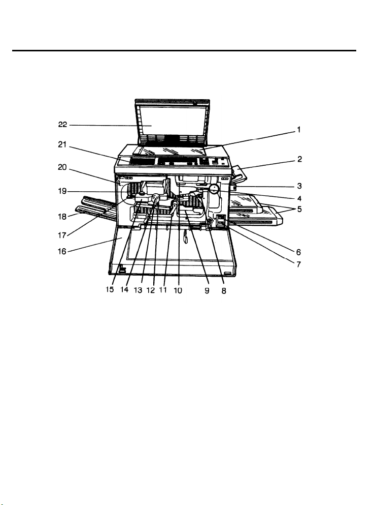
2.1 lNTERNAL/EXTERNAL
1. Exposure Glass
Position the original to be copied here.
2. Manual Feed Table
Open to manually feed the copy paper.
3. Key Counter Holder
Insert the key counter into this holder
[optional] before copying.
4. Toner Bottle Lever
Turn counterclockwise to remove the toner
bottle from its holder.
5. Cassettes
Hold the copy paper.
6. Total Counter
Shows the total number of copies made.
7. A3/11” x 17” Counter
Shows the total number of A3/11” x 17”
copies made (optional).
8. Registration Roller Knob
Turn to remove misfed paper.
1-4
Page 20

31 August 1989
9. Duplex Tray
Stores the copies before reverse side
copying.
10. Toner Bottle Holder
Swing down to replace the toner bottle.
11. Transport Unit Release Lever
Push down to lower the transport unit when
removing misfed paper.
12. Fusing Unit Release Lever
Press down to slide out the fusing unit.
13. Fork Gate Unit Lever
Press down to lower the fork gate unit.
14. Fusing Unit Knob
Turn clockwise to remove misfed paper.
15. Silicon Oil Bottle
Add silicone oil to this bottle when the Add
Oil indicator lights.
16. Front Cover
Open this cover when the Misfeed, Add
Toner, or Add Oil indicator lights.
17. Exit Guide Plate Tab
Raise this guide plate to gain access to the
exit area.
18. Copy Tray
Completed copies are delivered here.
19. Inverter Unit
Inverts and feeds copies to the duplex tray.
20. Main Switch
Turns on the machine.
21. Operation Panel
The copier’s keys and indicators are
located here.
22. Platen Cover
Lower the platen cover over originals before
copying.
1-5
Page 21
31 August 1989
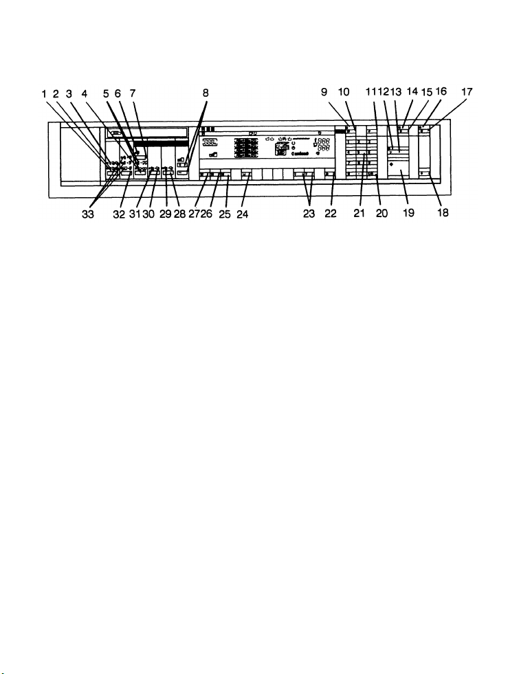
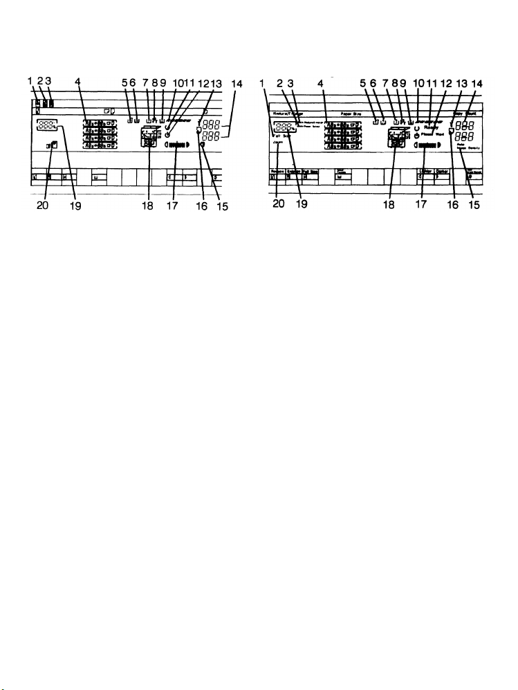
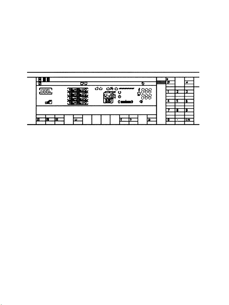
2.2 OPERATION PANEL A4/A3 Version
1. Sorter Key
Press to use the sorter. Select sort or stack
mode.
2. Stack Indicator
Lights when stack mode is selected.
3. Sort Indicator
Lights when sort mode is selected.
4.2 Single Copies Key
Press to make copies from bound originals
or two sided originals.
5.2 Single Copies Indicator
Lights when 2 single copies mode is
selected.
6. Margin Adjustment Indicator
Lights when Margin Adjustment mode is
selected.
7. Margin Adjustment Key
Press to create a margin on copies.
8. Zoom Keys
Press to alter the reproduction ratio in 1%
steps.
9. Guidance Indicator
Lights when guidance mode is selected.
10. Guidance Key
Press to select guidance mode.
11. Enter Key
Press after entering data.
12. Interrupt Indicator
Lights when interrupt mode is selected.
13. Interrupt Key
Press to make interrupt copies during a
copy run.
14. Program Indicator
Lights when the user program mode is
selected.
15. Program Key
Press to enter or recall user programs.
16. Timer Indicator
Lights when the machine has been turned
off by the weekly timer or automatic shut-off
timer.
17. Timer Key
Press to operate the copier after it has been
turned off by the weekly timer or automatic
shut-off timer.
1-6
Page 22
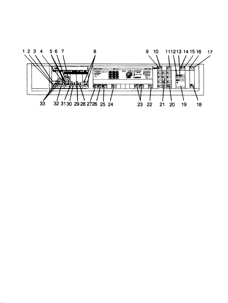
Letter/Legal Version
31 August 1989
18. Clear Modes Key
Press to clear the copier of previously
entered settings and modes.
19. Start Key
Press to start copying.
20. Clear/Stop Key
Press to cancel the copy number entered or
to stop copying.
21. Number Keys
Use the number keys to enter the number
of copies. Also, use to select user
programs and input original size and copy
size when in size magnification mode.
22. Auto Image Density Key
Press to select/clear automatic image
density mode.
23. Image Density Keys
Press to cancel automatic control and
manually select the image density level.
24. Select Cassette Key
Press to select a cassette.
25. Full Size Key
Press to change reproduction ratio to 100%.
26. Enlarge Key
Press to make enlarged copies.
27. Reduce Key
Press to make reduced copies.
28. Auto Reduce/Enlarge key
Press to select automatic reduce/enlarge
mode.
29. Auto Reduce/Enlarge Indicator
Lights when auto reduce/enlarge mode is
selected.
30. Auto Paper Select Key
Press to select automatic paper select
mode.
31. Auto Paper Select Indicator
Lights when automatic paper select mode is
selected.
32. Duplex Key
Press to select a duplex mode.
33. Duplex Indicators
Show selected duplex mode.
1-7
Page 23
31 August 1989
2.3 INDICATOR SCREEN A4/A3 Version
Letter/legal version
1. Full Size Mode Indicator
Lights when full size mode is selected.
2. Auto Paper Select Indicator
Lights when auto paper select mode is
selected.
3. Auto Reduce/Enlarge Indicator
Lights when auto reduce/enlarge mode is
selected.
4. Paper Size Indicator
Shows the selected cassette and paper size.
5. Empty Used Toner Indicator
Lights when the used toner bottle is full;
simultaneously, the Call Service indicator
blinks.
6. Add Toner Indicator
Blinks when the copier needs toner.
7. Add Oil Indicator
Lights when the silicone oil level is low.
8. Check Paper Path Indicator
Lights if there are misfeeds.
9. Load Paper Indicator
Lights when the selected cassette runs out
of paper.
10. Copy Cycle Indicator
Lights during a copy cycle.
11. Ready Indicator
Lights when the copier is ready to copy.
12. Wait Indicator
Lights during warm-up.
13. Call Service Indicator
Lights when the copier has a functional
problem.
14. Copy Counter Indicator
(Upper) Displays the number of copies
entered.
(Lower) While copying, it shows the number
of copies made. (If in count-down mode, it
shows the number of copies to be made.)
15. Auto Image Density Indicator
Lights when the copier is automatically
controlling image density.
16. Manual Feed Indicator
Lights when the copier is automatically
controlling image density.
17. Manual Image Density Indicator
Shows the selected image density.
18. Misfeed Location Display
Shows where to check inside the copier if
there is a misfeed.
19. Magnification Ratio Indicator
Shows the selected reproduction ratio.
20. Zoom Indicator
Lights when zoom mode is selected.
1-8
Page 24
31 August 1989
2.4 GUIDANCE DISPLAY
The Guidance Display shows information about keys and modes, and it guides you through
the procedures for operating the copier.
- Information about keys and modes -
When you need information about keys or modes, press the Guidance key and the key you
want information about.
After starting copier operation, you can get information about the current mode by pressing
the Guidance key.
Guidance is not available for the following Keys:
• Number keys
• Decimal key
• Start key
• Manual Image Density key
• Select Cassette key
1-9
Page 25
31 August 1989
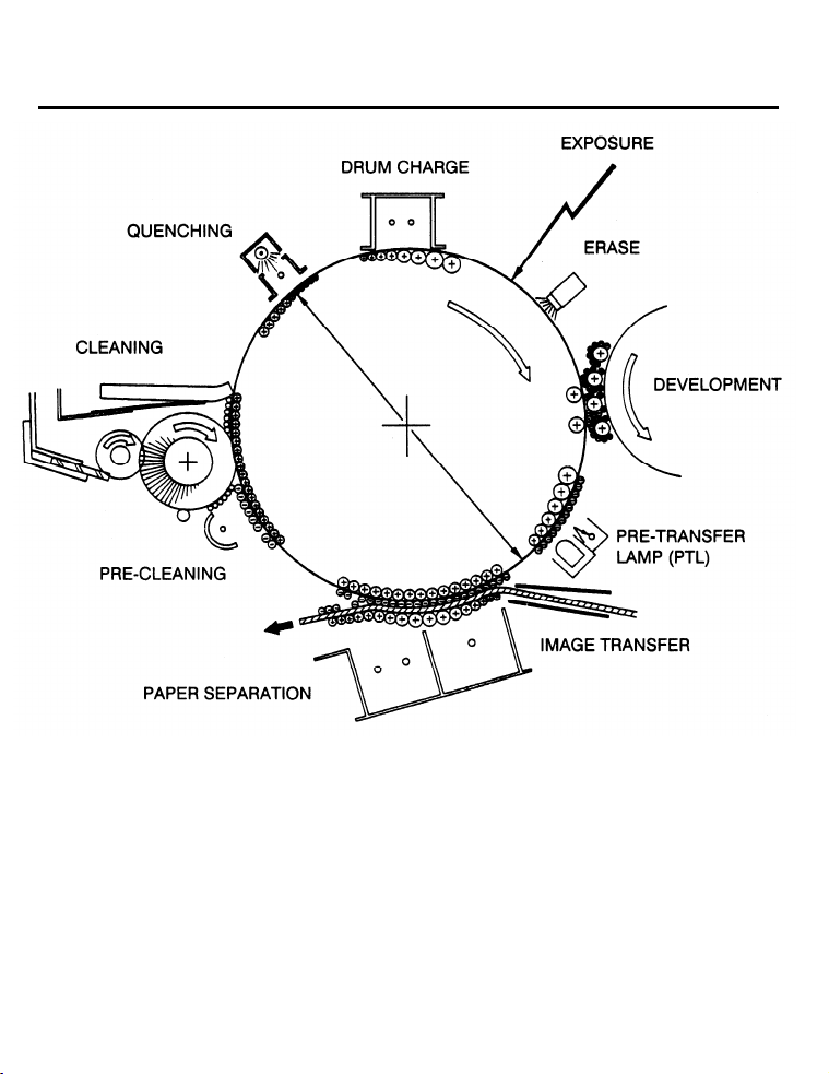
3. COPY PROCESSES AROUND THE DRUM
DRUM CHARGE
In the dark, the charge corona unit gives a uniform positive charge to the selenium drum. The
charge remains on the surface of the drum because the photoconductive selenium has
electrical resistance in the dark.
EXPOSURE
An image of the original is reflected to the selenium drum surface via the optics assembly. The
charge on the drum surface is dissipated in direct proportion to the intensity of the reflected
light, thus producing an electrical latent image on the drum surface.
1-10
Page 26

31 August 1989
ERASE
The erase lamp illuminates the areas of the charged drum surface that will not be used for the
copy image. The resistance of the drum in the illuminated areas drops and the charge on
those areas dissipates.
DEVELOPMENT
Negatively charged toner is attracted to the positively charged areas of the drum, thus
developing the latent image. (The negative triboelectric charge is caused by friction between
the carrier and toner particles.)
PRE-TRANSFER LAMP (PTL)
The PTL illuminates the drum to remove all positive charge from the exposed areas of the
drum. This prevents the toner particles from being reattracted to the drum surface during
paper separation and makes paper separation easier.
IMAGE TRANSFER
Paper is fed to the drum surface at the proper time so as to align the copy paper and the
developed image on the drum surface. Then, a strong positive charge is applied to the back
side of the copy paper, providing an electrical force which pulls the toner particles from the
drum surface to the copy paper. At the same time, the copy paper is electrically attracted to
the drum surface.
PAPER SEPARATION
A strong ac corona discharge is applied to the back side of the copy paper, reducing the
positive charge on the copy paper and breaking the electrical attraction between the paper
and the drum. Then, the stiffness of the copy paper causes it to separate from the drum
surface. The pick-off pawls help to separate paper which has low stiffness.
PRE-CLEANING
The pre-cleaning corona (PCC) applies an ac corona with a negative bias to the drum. This
removes the positive charge from the drum and makes the negative charge on the toner
remaining on the drum even.
CLEANING
The cleaning brush removes most of the toner on the drum and loosens the remainder. Then,
the bias roller, which has a positive potential, attracts the toner particles from the cleaning
brush to keep it clean. Finally, the cleaning blade scrapes off the loosened toner.
QUENCHING
The pre-quenching corona applies a positive corona charge to the selenium drum to eliminate
any negative charge remaining from the pre-cleaning corona. Then, light from the quenching
lamp electrically neutralizes the drum.
1-11
Page 27
31 August 1989
4. COPY CYCLE
1-12
Page 28
31 August 1989
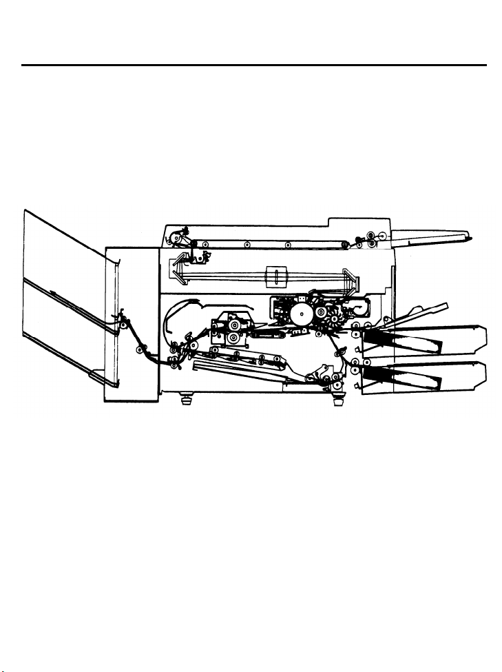
5. PAPER PATH
Paper feed starts from one of the four paper feed stations. The copy paper then follows one
of two paths inside the copier. The path followed depends on which mode the operator has
selected. For copy processing, all sheets follow the same path from the paper feed
mechanism through the fusing unit. After that, normal copies are delivered to the copy tray;
however, duplex copies are diverted for further processing. The following discussion follows
the route of a single sheet of paper through a duplex cycle.
1. PRIMARY PAPER PATH
Paper Feed:
An FRR (Feed and Reverse Roller) mechanism separates one sheet of paper from the paper
stack and feeds it to the registration rollers. If the paper is fed from the second, third, or fourth
station, relay rollers move the paper to the registration roller. The registration rollers are not
turning at this time. The paper buckles slightly when the leading edge reaches the registration
rollers. Buckling seats the sheet securely between the registration rollers and corrects skew.
Registration:
At the programmed time, the registration rollers start turning to feed the paper to the drum.
Image Transfer:
The toner image on the drum surface is pulled from the drum onto the passing paper by the
transfer corona.
1-13
Page 29

31 August 1989
Paper Separation:
The electrostatic attraction between the paper and the drum is broken by the separating
corona. The suction of the vacuum fan and the weight of the paper pulls the paper onto the
transport belt. The transport belt moves the paper with the developed copy image to the
fusing unit.
Fusing:
The paper passes between two rollers which bond the toner image to the paper by applying
heat and pressure. At this point the copy is complete, and the paper path splits two ways.
Ordinary copies go directly through the exit rollers to the copy tray. Duplex copies are
diverted to the inverter unit.
1-14
Page 30
31 August 1989
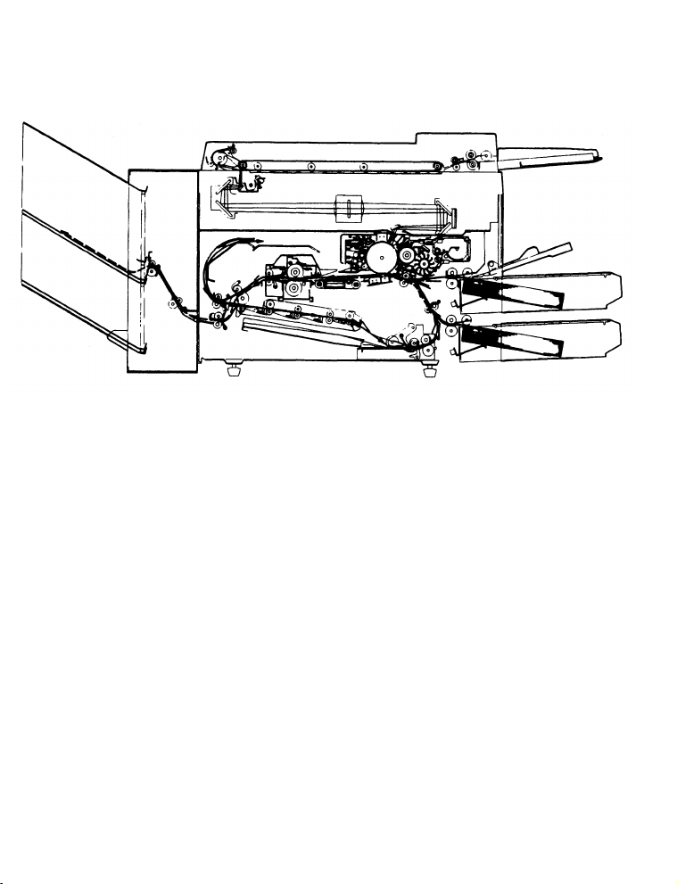
2. DUPLEX COPY PATH
Inverter Unit:
The junction gate directs the paper to the inverter unit, which inverts the copy and sends it to
the duplex transport unit.
Duplex Transport:
The duplex transport rollers move the copy to the right. The appropriate fork gate is opened
according to the paper size. Then, the copy is sent to the jogger unit through the duplex
delivery tray.
Jogger Unit:
The copies are neatly stacked in the jogger unit to prepare them for duplex paper feed.
Duplex Paper Feed
The copy is kept in the duplex tray until the operator sets the next original and presses the
Start key. Then the duplex feed mechanism feeds the copy up through the first relay rollers to
the registration rollers. After reaching the registration rollers, the sheet follows the same path
as when the front side was copied. However, this time the reverse side faces up to receive the
image.
1-15
Page 31

6. DRIVE LAYOUT
31 August 1989
1. Toner Supply Clutch
2. Development Drive Belt
3. Development Drive Gear
4. Development Motor
5. Drum Drive Pulley
6. Drum Drive Belt
7. Main Motor
8. Fusing/Duplex Drive Gears
9. Main Drive Belt
10. Exit Relay Roller Drive Sprocket
11. Inverter Roller Drive Gear
12. Exit Roller Drive Gear
13. Exit Drive Chain
14. Pulse Generator Drive Pulley
15. Registration Roller Drive Belt
16. Cleaning Drive Gear
17. Registration Clutch
18. Paper Feed Motor
19. Duplex Paper Feed Clutch
20. Relay Roller Clutch
21. Paper Feed Drive Chain
22. Second Paper Feed Clutch
23. First Paper Feed Clutch
1-16
Page 32

31 August 1989
7. MECHANICAL COMPONENT LAYOUT
1. Inverter Unit
2. Third Mirror
3. Second Mirror
4. First Mirror
5. Exposure Lamp
6. Fusing Unit
7. Document Feeder
8. Transport Unit
9. Lens
10. Cleaning Unit
11. Quenching Unit
12. Charge Corona Unit
13. Drum
14. Sixth Mirror
15. Toner Shield Glass
16. Erase Lamp Unit
17. Fourth Mirror
18. Fifth Mirror
19. Toner Tank
20. Development Unit
21. Manual Feed Table
22. First Cassette
23. Large Capacity Tray
24. Transfer/Separation Corona Unit
25. Jogger Unit
26. Fourth Cassette
27. Cassette Bank
28. Third Cassette
29. Duplex Delivery Tray
30. Fork Gate Unit
31. Duplex Transport Unit
32. Sorter
Page 33

31 August 1989
8. ELECTRICAL COMPONENT LAYOUT
1. Scanner Home Position Sensor
2. 4th and 5th Mirror Drive Motor
3. Toner Overflow Sensor 10. Exposure Lamp
4. Image Density Sensor PCB
5. PQC (Pre-quenching Corona Wire)
6. QL (Quenching Lamp)
7. Erase Lamp
8. Lens Home Position Sensor
9. Toner End Sensor
11. Scanner Overrun Sensor
12. 4th and 5th Mirror Home Position Sensor
13. Auto Density (AD) Sensor
14. Development Cooling Fan Motor
1-18
Page 34

31 August 1989
15. Cooling Blower Motor
16. Platen Cover Sensor
17. CC Cleaner Home Position Sensor
18. Key Counter (Option)
19. Manual Feed Sensor
20. CC Cleaner Motor
21. 1st Cassette Paper End Sensor
22. Manual Feed Paper End Sensor
23. 1st Paper Size Sensor
24. Registration Sensor
25. Pre-Transfer Lamp (PTL)
26. 2nd Cassette Paper End Sensor
27. Total Counter
28. A3/LTG Counter (Option)
29. 2nd Paper Size Sensor
30. SC Cleaner Motor
31. Duplex Stopper SOL
32. SC Cleaner Home Position Sensor
33. Duplex Paper Sensor
34. Drum Heater
35. Duplex Entrance Sensor
36. Front Door Safety Switch
37. Fusing Lamp
38. Oil End Sensor
39. Fusing Thermistor
40. Main Switch
41. AC Drive PCB
42. Power Supply Unit
43. Exit Sensor
44. Exit Relay Sensor
45. Inverter Exit Sensor
46. Fusing Exit Sensor
47. Thermofuse
48. Fusing Exhaust Fan Motor
49. Inverter Pressure SOL
50. Junction Gate SOL
51. Anticondensation Heater (option)
52. Lens Drive Motor
1-19
Page 35

31 August 1989
53. Main Motor
54. Main Motor Capacitor
55. Charge Fan Motor
56. Pick-off SOL
57. Registration MC
58. 1st Feed Relay MC
59. Paper Feed Motor
60. Toner Supply MC
61. Knocking Solenoid
62. Development Motor
63. Development Motor Capacitor
64. Paper Feed Motor Capacitor
65. Scanner Drive Motor
66. 1st Paper Feed MC
67. 1st Lift Sensor
68. 1st Lift Motor
1-20
Page 36

31 August 1989
69. 1st Pick-up SOL
70. Manual Feed SOL
71. 2nd Paper Feed MC
72. 2nd Lift Motor
73. 1st Relay Sensor
74. 2nd Lift Sensor
75. 2nd Pick-up SOL
76. Duplex Paper Feed MC
77. Duplex Positioning SOL
78. Duplex Pick-up SOL
79. Jogger Motor
80. Main Transformer
81. Jogger Home Position Sensor
82. Cleaning SOL
83. Pulse Generator
84. Fork Gate SOL 2
85. Fork Gate SOL 1
86. Transport Unit Safety Switch
87. Terminal Block
88. Fork Gate Unit Safety Switch
89. Noise Filter
90. Circuit Breaker
91. Power Relay
1-21
Page 37

31 August 1989
92. SSR PCB
93. PQC/Cleaning Bias Power Pack
94. CC/Developer Bias Power Pack
95. PTL/QL Stabilizer
96. Paper Feed PCB
97. Operation Panel PCB
98. TC/SC Power Pack
99. Vacuum Fan Motor
100. PCC Power Pack
101. Main PCB
102. Timer PCB
103. Optics PCB
1-22
Page 38

9. ELECTRICAL COMPONENT DESCRIPTIONS
31 August 1989
NAME
MOTORS
Main
Development Cooling
Blower
Fusing Exhaust Fan
Cooling Blower
Vacuum Fan
Scanner Drive
Lens Drive
4th/5th Mirror Drive
Jogger
Cleaner Motors
Charge Fan
Development
1st/2nd Lift Motors
Paper Feed
FUNCTION
Drives all main unit components except optics unit and
fans/blower. (100 Vac)
Blows air to the development unit bottom plate.
Removes heat from around the fusing unit. (100 Vac)
Prevents build up of hot air in the optics cavity. (100 Vac)
Provides suction so paper is held firmly on the transport
belt. (100 Vac)
Drives the scanner. (dc servo)
Positions the lens. (dc stepper)
Positions the 4th/5th mirror assembly. (dc stepper)
Drives the jogger plates to keep paper evenly stacked on
the duplex tray.
Clean charge and separation wires.
Ensures even charge on the surface of the drum.
Drives development unit.
Lift paper to the appropriate feed position.
Applies paper feed drive to the 1st and 2nd feed stations.
MAGNETIC CLUTCHES
Registration
1st Paper Feed
2nd Paper Feed
1st Feed Relay
Duplex Paper Feed
Toner Supply
Drives the registration roller
Starts paper feed from the first feed station.
Starts paper feed from the second feed station.
Drives the rollers of the copier relay unit.
Feeds paper from the duplex tray.
Drives toner supply roller.
1-23
Page 39

31 August 1989
SOLENOIDS
Cleaning
Pick-off
Junction Gate
Duplex Positioning
Manual Feed
1st and 2nd Fork Gate
Duplex Pick-up
Duplex Positioning
Inverter Pressure
Duplex Stopper
1st/2nd Pick-up
SWITCHES
Main
Front Door Safety
Transport Unit Safety
Fork Gate Unit Safety
Moves the cleaning blade against the drum.
Moves the pick-off pawls against the drum.
Energizes to direct copies to the duplex tray.
Raises and lowers the sponge roller.
Raises the pick-up roller when paper is fed from the manual
feed table.
In unison, open and close the appropriate fork gates
according to paper size.
Starts feed from duplex and aids the stopper solenoid.
Lowers positioning roller.
Controls the inverter pressure roller.
Stops copy in the jogger unit.
Starts paper feed from the cassettes.
Supplies power to the copier.
Cuts ac power line.
Cuts 24-volt lines.
Cuts 24-volt lines.
SENSORS
Pulse Generator
Exit
Oil End
Toner Overflow
Toner End
Registration
Manual Feed
Scanner Home
Supplies timing pulses to the main board.
Detects misfeeds.
Detects the low oil condition.
Detects when the used toner bottle is full.
Detects when it is time to add toner.
Detects misfeeds.
Detects when the manual feed table is open.
Informs the CPU when the scanner is at the home position.
1-24
Page 40

31 August 1989
Lens Home
4th/5th Mirror Home
1st Paper Size
1st Paper End
2nd Paper Size
2nd Paper End
Scanner Overrun
1st Relay
Jogger Home
Duplex Paper
Duplex Entrance
Image Density
Auto Density (AD)
CC Cleaner Home Position
SC Cleaner Home Position
Platen Cover
Manual Feed Paper End
Fusing Exit
Inverter Exit
1st Lift
2nd Lift
Informs the CPU when the lens is at the full size position.
Informs the CPU when the 4th/5th mirror assembly is at
the full size position.
Detects the paper size in the first cassette.
Informs the CPU when the first cassette runs out of paper.
Detects the paper size in the second cassette.
Informs the CPU when the second cassette runs out of
paper.
Informs the CPU, if the scanner overshoots the home
position.
Detects misfeeds.
Informs the CPU when the jogger plates are at the home
position.
Detects whether or not paper is on the duplex tray.
Misfeed detector
Detects the density of the image on the drum.
Senses the background density of the original.
Informs the CPU when the charge wire cleaner has
reached home position.
Informs the CPU when the separation wire cleaner has
reached home position.
Informs the CPU that the platen cover is up or down.
Informs the CPU that there is no paper in the manual feed
tray.
Detects misfeeds.
Detects misfeeds.
Detects whether paper has been raised to the proper paper
feed position.
Detects whether paper has been raised to the proper paper
feed position.
1-25
Page 41

31 August 1989
THERMISTORS
Drum
Bias
Fusing
POWER PACKS/STABILIZER
Power Pack - T/S
Power Pack - CC/Bias
Power Pack - Q/BR
Power Pack - PCC
Lamp Stabilizer
HEATERS
Drum
Anticondensation (option)
Monitors the temperature around the drum. The CPU
selects the bias compensation range based on its input.
Monitors the temperature around the drum and controls
development bias compensation.
Monitors the fusing temperature and turns the fusing lamp
on/off.
Provides high voltage for the T/S coronas.
Provides high voltage for the charge corona and the
development roller bias.
Provides high voltage for the quenching corona and the
cleaning bias roller.
Provides high voltage for the pre-cleaning corona.
Provides high voltage for the quenching and pre-transfer
lamps.
Warms the drum when the main switch is off.
Prevents moisture from forming on the optics.
LAMPS
Exposure
Fusing
Erase
Quenching
Pre-transfer
PRINTED CIRCUIT BOARDS
Main
Applies high intensity light to the original for exposure.
Provides heat to the fusing unit.
Discharges the drum outside the image area. Erases
lead/trail edge.
Neutralizes any charge remaining on the drum surface after
cleaning.
Reduces charge on the drum surface before transfer.
Controls all copier functions both directly and through other
PCBs.
1-26
Page 42

31 August 1989
Optics
Operation Panel
Paper Feed
AC Drive
Timer
COUNTERS
Total
A3/11” x 17”
Key
CIRCUIT BREAKERS
Circuit Breaker
TRANSFORMERS
Main
OTHERS
Power Supply Unit
Thermofuse
AC Power Relay
Noise Filter
Main Motor Capacitor
Development Motor Capacitor
Paper Feed Capacitor
Controls the speed of the scanner, the position of the lens,
and the position of the mirrors.
Controls the LED matrix, and monitors the key matrix.
Interfaces with overall paper feed; receives input from
paper size and paper end sensors.
Drives all ac motors, the exposure lamp, and the fusing
lamp.
Controls weekly timer and timer functions.
Keeps track of the total number of copies made.
Keeps track of the total number of A3/11” x 17” copies
made. (Option)
Used for control of authorized use. Copier will not operate
until installed. (Option)
Guards against voltage surges in the input power.
Steps down the wall voltage to 100 Vac.
Rectifies 100 Vac input and outputs dc voltages.
Provides back-up overheat protection in the fusing unit.
Controls main power.
Removes electrical noise.
Start capacitor
Start capacitor
Start capacitor
1-27
Page 43

31 August 1989
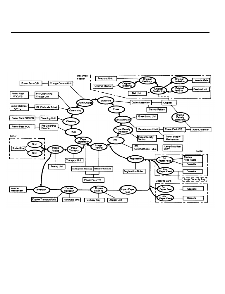
10. OVERALL MACHINE CONTROL
1-28
Page 44

31 August 1989
11. AC AND DC POWER DISTRIBUTION
The illustration on this page shows the electrical power distribution in block form.
AC power (115/220 volts) is supplied from the wall outlet directly to the fusing lamp and the
step-down transformer. The transformer supplies 100 volts ac to the power supply unit, SSR
board, ac drive board, and to one side of the fans, motors, heaters, paper bank, and sorter.
The power supply unit has four dc fuses and one ac fuse.
1-29
Page 45

SECTION 2
DETAILED SECTION
DESCRIPTIONS
Page 46

Contents
DETAILED SECTION DESCRIPTIONS
1. DRUM . . . . . . . . . . . . . . . . . . . . . . . . . . . . . . . . . . . . . . . . . . . . . . . . 2-1
1.1 SELENIUM DRUM CHARACTERISTICS . . . . . . . . . . . . . . . . . . . . . . . . . . . . . . . . . 2-1
1.2 HANDLING THE DRUM . . . . . . . . . . . . . . . . . . . . . . . . . . . . . . . . . . . . . . . . . . . . . . 2-1
1.3 DRUM HEATER CONTROL . . . . . . . . . . . . . . . . . . . . . . . . . . . . . . . . . . . . . . . . . . . 2-3
2. DRUM CHARGE . . . . . . . . . . . . . . . . . . . . . . . . . . . . . . . . . . . . . . . . 2-4
2.1 OVERVIEW . . . . . . . . . . . . . . . . . . . . . . . . . . . . . . . . . . . . . . . . . . . . ., . . . . . . . . . . 2-4
2.2 WlRE CLEANER . . . . . . . . . . . . . . . . . . . . . . . . . . . . . . . . . . . . . . . . . . . . . . . . . . . . 2-5
2.3 CHARGE CORONA POWER PACK . . . . . . . . . . . . . . . . . . . . . . . . . . . . . . . . . . . . . 2-6
3. OPTICS . . . . . . . . . . . . . . . . . . . . . . . . . . . . . . . . . . . . . . . . . . . . . . . 2-7
3.1 OVERVIEW . . . . . . . . . . . . . . . . . . . . . . . . . . . . . . . . . . . . . . . . . . . . . . . . . . . . . . . . 2-7
3.2 EXPOSURE LAMP CONTROL . . . . . . . . . . . . . . . . . . . . . . . . . . . . . . . . . . . . . . . . . 2-9
3.3 SCANNER DRIVE . . . . . . . . . . . . . . . . . . . . . . . . . . . . . . . . . . . . . . . . . . . . . . . . . . 2-10
3.4 SCANNER MOTOR CONTROL . . . . . . . . . . . . . . . . . . . . . . . . . . . . . . . . . . . . . . . 2-11
3.5 LENS/MIRROR POSlTlONING . . . . . . . . . . . . . . . . . . . . . . . . . . . . . . . . . . . . . . . . 2-12
3.6 FOURTH AND FlFTH MIRROR ASSEMBLY . . . . . . . . . . . . . . . . . . . . . . . . . . . . . . 2-15
3.7 ORIGlNAL SlZE DETECTION . . . . . . . . . . . . . . . . . . . . . . . . . . . . . . . . . . . . . . . . . 2-17
3.8 RELATED SERVICE CALL CONDITIONS . . . . . . . . . . . . . . . . . . . . . . . . . . . . . . . . 2-17
4. ERASE . . . . . . . . . . . . . . . . . . . . . . . . . . . . . . . . . . . . . . . . . . . . . . .
4.1 OVERVIEW . . . . . . . . . . . . . . . . . . . . . . . . . . . . . . . . . . . . . . . . . . . . . . . . . . . . . . . 2-22
4.2 LEAD EDGE AND TRAILING EDGE ERASE . . . . . . . . . . . . . . . . . . . . . . . . . . . . . 2-23
4.3 SIDE ERASE . . . . . . . . . . . . . . . . . . . . . . . . . . . . . . . . . . . . . . . . . . . . . . . . . . . . . . 2-23
4.4 EDGE ERASE FUNCTION . . . . . . . . . . . . . . . . . . . . . . . . . . . . . . . . . . . . . . . . . . . 2-24
4.5 ERASE LAMP CIRCUIT . . . . . . . . . . . . . . . . . . . . . . . . . . . . . . . . . . . . . . . . . . . . . . 2-25
5. DEVELOPMENT . . . . . . . . . . . . . . . . . . . . . . . . . . . . . . . . . . . . . . . 2-26
5.1 OVERVIEW . . . . . . . . . . . . . . . . . . . . . . . . . . . . . . . . . . . . . . . . . . . . . . . . . . . . . . . 2-26
5.2 DEVELOPER EXCHANGE UNIT . . . . . . . . . . . . . . . . . . . . . . . . . . . . . . . . . . . . . . . 2-27
5.3 DRIVE MECHANlSM . . . . . . . . . . . . . . . . . . . . . . . . . . . . . . . . . . . . . . . . . . . . . . . . 2-28
5.4 IMAGE DENSlTY CONTROL . . . . . . . . . . . . . . . . . . . . . . . . . . . . . . . . . . . . . . . . . 2-30
5.6 BIAS CONTROL CIRCUIT . . . . . . . . . . . . . . . . . . . . . . . . . . . . . . . . . . . . . . . . . . . . 2-36
5.7 RELATED SERVlCE CALL CONDlTIONS . . . . . . . . . . . . . . . . . . . . . . . . . . . . . . . . 2-37
2-22
Page 47

6. TONER DENSITY DETECTION AND TONER SUPPLY . . . . . . . . . 2-38
6.1 TONER SUPPLY . . . . . . . . . . . . . . . . . . . . . . . . . . . . . . . . . . . . . . . . . . . . . . . . . . . 2-38
6.2 BOTTLE DRIVE MECHANISM . . . . . . . . . . . . . . . . . . . . . . . . . . . . . . . . . . . . . . . . 2-39
6.3 TONER DENSITY DETECTION . . . . . . . . . . . . . . . . . . . . . . . . . . . . . . . . . . . . . . . 2-40
6.4 TONER DENSITY CONTROL . . . . . . . . . . . . . . . . . . . . . . . . . . . . . . . . . . . . . . . . . 2-41
6.5 TONER SUPPLY AMOUNT . . . . . . . . . . . . . . . . . . . . . . . . . . . . . . . . . . . . . . . . . . . 2-42
6.6 TONER END DETECTION . . . . . . . . . . . . . . . . . . . . . . . . . . . . . . . . . . . . . . . . . . . 2-44
6.7 TONER OVERFLOW SENSOR CIRCUIT . . . . . . . . . . . . . . . . . . . . . . . . . . . . . . . . 2-45
7. lMAGE TRANSFER AND PAPER SEPARATION . . . . . . . . . . . . . . 2-46
7.1 PRE-TRANSFER LAMP (PTL) . . . . . . . . . . . . . . . . . . . . . . . . . . . . . . . . . . . . . . . . . 2-46
7.2 IMAGE TRANSFER . . . . . . . . . . . . . . . . . . . . . . . . . . . . . . . . . . . . . . . . . . . . . . . . . 2-47
7.3 PAPER SEPARATION . . . . . . . . . . . . . . . . . . . . . . . . . . . . . . . . . . . . . . . . . . . . . . . 2-49
7.4 TRANSFER/SEPARATION CORONA POWER PACK . . . . . . . . . . . . . . . . . . . . . . 2-50
7.5 PICK-OFF MECHANISM . . . . . . . . . . . . . . . . . . . . . . . . . . . . . . . . . . . . . . . . . . . . . 2-52
7.6 PICK-OFF TIMING . . . . . . . . . . . . . . . . . . . . . . . . . . . . . . . . . . . . . . . . . . . . . . . . . . 2-53
7.7 PRE-TRANSFER LAMPAND QUENCHING LAMP CIRCUIT . . . . . . . . . . . . . . . . . 2-54
8. DRUM CLEANING . . . . . . . . . . . . . . . . . . . . . . . . . . . . . . . . . . . . . 2-55
8.1 OPERATION . . . . . . . . . . . . . . . . . . . . . . . . . . . . . . . . . . . . . . . . . . . . . . . . . . . . . . 2-55
8.2 PRE-CLEANING CORONA AND BIAS ROLLER . . . . . . . . . . . . . . . . . . . . . . . . . . 2-56
8.3 DRIVE MECHANISM . . . . . . . . . . . . . . . . . . . . . . . . . . . . . . . . . . . . . . . . . . . . . . . . 2-57
8.4 CLEANING BLADE . . . . . . . . . . . . . . . . . . . . . . . . . . . . . . . . . . . . . . . . . . . . . . . . . 2-58
8.5 CLEANING SOLENOID CIRCUIT. . . . . . . . . . . . . . . . . . . . . . . . . . . . . . . . . . . . . . 2-59
8.6 PRE-CLEANING CORONA CIRCUIT . . . . . . . . . . . . . . . . . . . . . . . . . . . . . . . . . . . 2-60
9. QUENCHING . . . . . . . . . . . . . . . . . . . . . . . . . . . . . . . . . . . . . . . . . . 2-61
9.1 OPERATION . . . . . . . . . . . . . . . . . . . . . . . . . . . . . . . . . . . . . . . . . . . . . . . . . . . . . . 2-61
9.2 PRE-QUENCHING CORONA CIRCUIT . . . . . . . . . . . . . . . . . . . . . . . . . . . . . . . . . 2-62
10. PAPER FEED . . . . . . . . . . . . . . . . . . . . . . . . . . . . . . . . . . . . . . . . . 2-63
10.1 OVERVIEW . . . . . . . . . . . . . . . . . . . . . . . . . . . . . . . . . . . . . . . . . . . . . . . . . . . . . . 2-63
10.2 LIFT MECHANISM AND PAPER END DETECTION . . . . . . . . . . . . . . . . . . . . . . 2-64
10.3 ROLLER FUNCTION . . . . . . . . . . . . . . . . . . . . . . . . . . . . . . . . . . . . . . . . . . . . . . . 2-66
10.4 SLIP CLUTCH MECHANISM . . . . . . . . . . . . . . . . . . . . . . . . . . . . . . . . . . . . . . . . 2-68
10.5 PAPER FEED DRIVE . . . . . . . . . . . . . . . . . . . . . . . . . . . . . . . . . . . . . . . . . . . . . . . 2-69
10.6 MANUAL FEED . . . . . . . . . . . . . . . . . . . . . . . . . . . . . . . . . . . . . . . . . . . . . . . . . . . 2-71
10.7 RELAY FEED AND REGISTRATION . . . . . . . . . . . . . . . . . . . . . . . . . . . . . . . . . . . 2-72
Page 48

10.8 PAPER SIZE SENSORS . . . . . . . . . . . . . . . . . . . . . . . . . . . . . . . . . . . . . . . . . . . . 2-74
10.9 LIFT MOTOR CONTROL AND PAPER END DETECTION . . . . . . . . . . . . . . . . . . 2-75
11. PAPER TRANSPORT
11.1 OVERVIEW . . . . . . . . . . . . . . . . . . . . . . . . . . . . . . . . . . . . . . . . . . . . . . . . . . . . . . 2-77
11.2 TRANSPORT UNIT RELEASE MECHANISM . . . . . . . . . . . . . . . . . . . . . . . . . . . . 2-78
. . . . . . . . . . . . . . . . . . . . . . . . . . . . . . . . . .2-77
12. IMAGE FUSING AND PAPER EXIT . . . . . . . . . . . . . . . . . . . . . . . 2-79
12.1 OVERVIEW . . . . . . . . . . . . . . . . . . . . . . . . . . . . . . . . . . . . . . . . . . . . . . . . . . . . . . 2-79
12.2 FUSING DRIVE MECHANISM . . . . . . . . . . . . . . . . . . . . . . . . . . . . . . . . . . . . . . . 2-80
12.3 ENTRANCE GUIDE . . . . . . . . . . . . . . . . . . . . . . . . . . . . . . . . . . . . . . . . . . . . . . . . 2-81
12.4 OIL SUPPLY AND CLEANlNG . . . . . . . . . . . . . . . . . . . . . . . . . . . . . . . . . . . . . . . 2-82
12.5 OIL END SENSOR . . . . . . . . . . . . . . . . . . . . . . . . . . . . . . . . . . . . . . . . . . . . . . . . 2-83
12.6 FUSlNG EXlT ASSEMBLY . . . . . . . . . . . . . . . . . . . . . . . . . . . . . . . . . . . . . . . . . . 2-84
12.7 FUSING CONTROL . . . . . . . . . . . . . . . . . . . . . . . . . . . . . . . . . . . . . . . . . . . . . . . . 2-85
12.8 SERVlCE CALL CONDlTIONS . . . . . . . . . . . . . . . . . . . . . . . . . . . . . . . . . . . . . . . 2-88
13. PAPER EXIT . . . . . . . . . . . . . . . . . . . . . . . . . . . . . . . . . . . . . . . . .
13.1 OVERVIEW . . . . . . . . . . . . . . . . . . . . . . . . . . . . . . . . . . . . . . . . . . . . . . . . . . . . . . 2-90
13.2 EXIT ROLLER DRlVE MECHANlSM . . . . . . . . . . . . . . . . . . . . . . . . . . . . . . . . . . 2-91
14. DUPLEX . . . . . . . . . . . . . . . .
14.1 INVERSION . . . . . . . . . . . . . . . . . . . . . . . . . . . . . . . . . . . . . . . . . . . . . . . . . . . . . 2-92
14.2 DUPLEX TRANSPORT . . . . . . . . . . . . . . . . . . . . . . . . . . . . . . . . . . . . . . . . . . . . . 2-96
14.3 DUPLEX STACKING . . . . . . . . . . . . . . . . . . . . . . . . . . . . . . . . . . . . . . . . . . . . . . . 2-99
14.4 DUPLEX TRAY SENSORS . . . . . . . . . . . . . . . . . . . . . . . . . . . . . . . . . . . . . . . . . 2-103
14.5 DUPLEX PAPER FEED . . . . . . . . . . . . . . . . . . . . . . . . . . . . . . . . . . . . . . . . . . . . 2-104
14.6 RELATED SERVICE CALL CONDlTlONS . . . . . . . . . . . . . . . . . . . . . . . . . . . . . . 2-107
. . . . . . . . . . . . . . . . . . . . . . . . . . . . .
2-90
2-92
15. OTHER CIRCUITS . . . . . . . . . . . . . . . . . . . . . . . . . . . . . . . . . . . 2-108
15.1 DC POWER DISTRIBUTION . . . . . . . . . . . . . . . . . . . . . . . . . . . . . . . . . . . . . . . . 2-108
15.2 SAFETY SWITCH ClRCUITS . . . . . . . . . . . . . . . . . . . . . . . . . . . . . . . . . . . . . . . . 2-109
15.3 AC COMPONENT CONTROL . . . . . . . . . . . . . . . . . . . . . . . . . . . . . . . . . . . . . . . 2-110
15.4 CORONA CLEANER MOTORS . . . . . . . . . . . . . . . . . . . . . . . . . . . . . . . . . . . . . . . 2-111
15.5 PULSE GENERATOR . . . . . . . . . . . . . . . . . . . . . . . . . . . . . . . . . . . . . . . . . . . . . 2-112
15.6 MAGNETIC CLUTCH AND SOLENOID CONTROL . . . . . . . . . . . . . . . . . . . . . . 2-113
15.7 SENSOR OPERATION . . . . . . . . . . . . . . . . . . . . . . . . . . . . . . . . . . . . . . . . . . . . 2-114
15.8 COUNTER ClRCUITS . . . . . . . . . . . . . . . . . . . . . . . . . . . . . . . . . . . . . . . . . . . . . 2-117
Page 49

31 August 1989
1. DRUM
1.1 SELENIUM DRUM CHARACTERISTICS
Selenium has the following characteristics:
•
Accepts a high positive electrical charge in the dark. (The electrical resistance of selenium
is high in the absence of light.)
•
Dissipates the electrical charge when exposed to light. (Exposure to light greatly enhances
the conductivity of selenium.)
•
Dissipates the electrical charge in direct proportion to the intensity of the light.
That is, where stronger light is directed to the selenium surface, a smaller voltage
remains on the selenium.
The sensitivity of selenium changes slightly with variations in the surface temperature of the
drum. (Under cool conditions, the drum conductivity decreases. This will result in background
or excessive image density.) As a countermeasure, the development bias is changed to
compensate for temperature variations around the drum. Also, while the copier is off, the drum
heater warms the drum.
Drum sensitivity also depends on how long the drum has rested between copy runs. The
copier’s CPU compensates for changes in drum sensitivity due to rest time by changing the
development bias. This prevents variations in image density at the beginning of copy runs.
The selenium drum used in this model has high sensitivity, good color reproduction, and good
reproduction of low contrast originals (pencil originals, etc.)
1.2 HANDLING THE DRUM
Never touch the drum surface with bare hands.
Store the drum in a cool, dry place away from heat.
When cleaning the drum, always wear a pair of gloves. Do not throw away cotton
used for cleaning. Bring it back to the service depot for disposal according to local
regulations.
Prime the drum with setting powder when the drum, cleaning blade, or cleaning brush are
replaced. Do this within one minute in a location not exposed to strong light.
2-1
Page 50

31 August 1989
• Drum conditioning is necessary when a new drum is installed. In addition, it should
be done at the following times:
1) When image density is reduced due to overexposure of the drum
2) After cleaning the drum
3) When the oxide layer on the drum is lightly scratched
• When installing or removing the drum, always keep it in the protective sleeve.
• Before installing or removing the drum, pull out the cleaning unit part way so that the
pick-off pawls do not scratch the drum surface.
• Before placing the protective sleeve on the drum while it is in the copier, always take out
the development unit. Otherwise, the edge of the sleeve will scrape developer from the
development roller.
2-2
Page 51

31 August 1989
1.3 DRUM HEATER CONTROL
The drum heater receives 100 volts ac only when the main switch is turned off. When the main
switch is turned on, the 100 volt ac current stops flowing.
2-3
Page 52

31 August 1989
2. DRUM CHARGE
This copier uses a dual wire corotron unit and a highly sensitive selenium drum. The corona
wires [A] generate a flow of positive ions when the charge power pack applies a high positive
voltage to the corona unit. The drum coating [B] receives a uniform positive charge as it
rotates past the corona unit.
The charge fan [C] provides a smooth flow of air to the interior of the charge corona unit [D]
to prevent uneven build up of positive ions. (An uneven build up of positive ions could cause
uneven image density.)
2-4
Page 53

31 August 1989
2.2 WIRE CLEANER
Paper dust or toner particles on the corona wires [A] may interfere with charging. The wire
cleaner [B] corrects this problem by automatically wiping the charge corona wires clean. Pads
on the wire cleaner bracket clean the corona wires as the dc motor [C] drives the cleaner
bracket from the home position to the rear end of the corona unit and then back again.
Operation of the wire cleaner is based on copy count. A RAM counter keeps track of the
number of copies made since the last time the wires were cleaned. The CPU checks this
counter each time the copier is turned on. If the count is greater than 5,000 at that time, the
CPU turns on the cleaner motor to clean the corona wires. Simultaneously, it resets the
counter to zero.
During a cleaning cycle, the cleaner motor drives the wire cleaner toward the rear endblock.
Normally, the cleaner reaches the rear endblock in about 10 seconds, but the motor stays on
for 20 seconds to ensure that the cleaner moves the full distance. Then, the motor reverses to
drive the wire cleaner to the home position. The motor turns off when the cleaner activates the
home position sensor [D]. If the home position sensor is not activated within 20 seconds after
reverse drive is initiated, the CPU stops the motor and adds 1 to the count stored in SP mode
121 (SC85 and 86). Copies can still be made and there is no service call indication on the
operation panel.
Note:
SC 85 –> The home position sensor does not turn ON.
SC 86 –> The home position sensor does not turn OFF.
2-5
Page 54
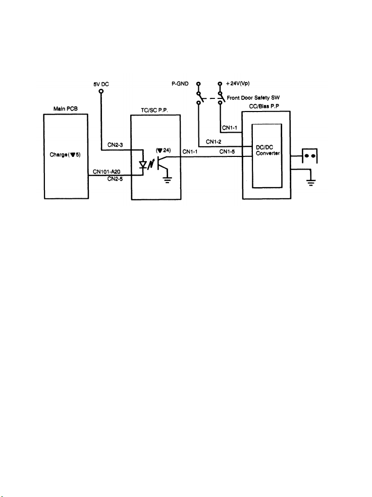
31 August 1989
2.3 CHARGE CORONA POWER PACK
The circuit operation for the charge corona begins with the input of +5 volts (Vc) at CN2-3.
This voltage powers the LED of the photocoupler.
Additionally, 24 volts (Vp) enters the power pack at CN1-1. This power supply is used to
produce the high voltage corona. This voltage is interrupted if the front door safety switch
opens.
The charge corona turns on 260 milliseconds before the lead edge of the copy is detected by
the registration sensor. A LOW signal from the CPU (CN101-A20) is sent to the CC/B power
pack through the TC/SC power pack.
The OFF timing of the charge corona power pack varies according to the paper size being
used.
2-6
Page 55

31 August 1989
3. OPTICS
3.1 OVERVIEW
During the copy cycle, an image of the original is reflected onto the surface of the drum [I] via
the optics assembly. The optics assembly consists of the following parts:
1. First Scanner [A]:
2. Second Scanner [D]:
3. Lens (F5, f = 215 mm) [E]
4. Fourth and Fifth Mirror Assembly [F]:
5. Sixth Mirror [G]:
6. Toner Shield Glass [H]
Exposure lamp [B] (85V, 160W)
First mirror
AD (Auto Density) sensor [C]
Second mirror
Third mirror
Fourth Mirror
Fifth Mirror
2-7
Page 56

31 August 1989
This copier has nine standard reproduction ratios: five reductions, three enlargements and full
size. In addition, it has a zoom function. The reproduction ratio can be selected in one
percent steps from 60% to 155%.
A servomotor drives the first and second scanners during the copy cycle. This motor is
controlled by the optics PCB, which changes the motor speed depending on the reproduction
ratio. Two stepper motors change the position of the lens and the fourth and fifth mirror
assembly to change the reproduction ratio. The sixth mirror is fixed.
The fiber optic cable used for the auto density sensor (ADS) is mounted on the first scanner.
The ADS collects light reflected from the original in auto density sensing mode.
2-8
Page 57

31 August 1989
3.2 EXPOSURE LAMP CONTROL
After the Start key is pressed, the main PCB sends the exposure lamp trigger signal [C] to
CN501-6 on the ac drive board. The width of the lamp trigger pulse is based on the setting of
SP mode #48 and on the zero-cross signal [B] from the ac drive board. This lamp trigger
pulse activates the triac on the ac drive board, which provides exposure lamp power [D] from
the 100-volt ac line [A].
The power supplied to the exposure lamp is also provided to the lamp monitor circuit, which
rectifies it and supplies it to the Sub CPU analog port [E]. This allows fine tuning of the trigger
pulse width and ensures accurate circuit operation. The lamp monitor signal is also monitored
by a timer circuit in the main board. Should this signal stay active for longer than 15 seconds,
the main board energizes relay RA on the ac drive board. This causes relay RA1 to
de-energize, removing power from the exposure lamp. The copier stops and SC #12 is
displayed.
Use SP mode #51 to display lamp voltage in the guidance display.
2-9
Page 58

31 August 1989
3.3 SCANNER DRIVE
This model uses a dc servomotor [A] to drive the first [B] and second [C] scanners.
This first scanner is attached to the scanner drive wire by the wire clamp [D]. The second
scanner is connected to the scanner drive wire by a movable pulley [E] (the second scanner
pulley).
The second scanner pulley moves the second scanner at half the velocity of the first scanner.
This maintains the focal distance between the original and the lens during scanning. This
relationship can be expressed as follows:
2(V2r)
= VD/r
r:
Reproduction
First Scanner Velocity (when the Reproduction ratio is “r”)
V1r:
V2r:
Second Scanner Velocity (when the Reproduction ratio is “r”)
Drum Peripheral Velocity (300 mm/s)
VD:
V1r =
where
The first scanner wire clamp also actuates the home position sensor. The CPU on the optics
board controls both the registration and return timing.
2-10
Page 59

31 August 1989
3.4 SCANNER MOTOR CONTROL
The scanner drive motor is a dc servomotor. The CPU on the optics board controls the speed
of this servomotor. The main CPU and the optics CPU communicate through a serial interface
bus (TXD/RXD).
After the main CPU sends the scanner start signal to the optics CPU, the optics CPU receives
the drum speed data from the main PCB (pulse generator).
An encoder on the servomotor has two magnetic sensors that generate two pulse signals.
The optics CPU monitors the scanner speed and direction by these pulse signals.
Based on the drum speed and encoder data, the optics CPU determines the proper speed for
the scanner drive motor to obtain proper vertical magnification. The optics CPU sends the
speed data to the timer IC, which controls the scanner motor circuit.
The home position sensor informs the optics board when the first scanner is in the home
position.
2-11
Page 60

31 August 1989
3.5 LENS/MIRROR POSITIONING
Lens Drive
The lens drive motor (stepper motor) [A] changes the lens position according to the selected
reproduction ratio to provide the proper horizontal magnification between the lens and the
drum’s surface.
The output gear of the lens drive motor engages the gears [B] of the lens drive pulley. The
lens drive wire [C] is wrapped around the lens drive pulley and is connected to the lens drive
bracket [D]. The rotation of the lens drive pulley moves the lens back and forth in discrete
steps.
2-12
Page 61

[A] - Lens Drive Pulley
[B] - Lens Housing
31 August 1989
The lens home position sensor [C] informs the optics PCB when the lens [D] is at the full-size
position (home position). The optics PCB determines the lens stop position in reduction and
enlargement modes by counting the number of steps from the home position. When the
reproduction ratio is changed, the lens moves directly to the selected magnification position.
2-13
Page 62

31 August 1989
Home position is checked by moving
the lens from the enlargement side
towards the reduction side. So, when
home position is checked, a LOW to
HIGH to LOW signal is present at
CN305-9 of the optics board. This
occurs when the actuator blade enters
and exits the lens home position
sensor. The lens only references home
position when going to full size (at
power up, when modes are cleared,
when full size is selected.) The lens
always overshoots the selected
magnification ratio position by 40 steps
to eliminate mechanical play when
going from enlargement to reduction.
2-14
Page 63

3.6 FOURTH AND FIFTH MIRROR ASSEMBLY
31 August 1989
When the reproduction ratio is changed, the stepper motor [A] moves the fourth and fifth
mirror assembly [B] using the wire [C] and pulleys [D]. This provides the proper focal
distance between the original and the drum.
When the fourth and fifth mirror assembly is in the full-size position, the actuator [E] on the
assembly actuates the fourth/fifth mirror home position sensor [F]. This signal goes to the
optics CPU.
2-15
Page 64

31 August 1989
Fourth and Fifth Mirror Assembly Positioning
The mirror home position sensor informs the optics CPU when the fourth and fifth mirror
assembly is at the home position. The home position is determined by a LOW to HIGH to
LOW change on CN305-12 of the optics board.
When a reproduction ratio is selected, the operation panel PCB sends this information to the
main board. The main board then sends the appropriate trigger signals through the serial line
to the optics board.
When moving away from the home position, the mirror drive pulley turns clockwise and moves
directly to the selected position. However, when moving towards the home position (pulley
turns counterclockwise), the mirror assembly overshoots the selected position by 40 steps
(adjust by SP 47) and then returns to the selected position. This takes out any mechanical
play.
2-16
Page 65

31 August 1989
3.7 ORIGINAL SIZE DETECTION NOTE:
With the F33\34, original size detection is performed using the OL and OW sensors in
the ARDF unit. For more information, see the ARDF options section.
3.8 RELATED SERVICE CALL CONDITIONS Code #11: Exposure Lamp Malfunction
Definition:
Lights if the lamp filament breaks or if the lamp turns on during ready or please wait modes.
Observation:
When the main switch is turned on, call service code “11” is displayed.
Points to Check:
If the lamp is lit during the ready or please wait mode, check CN103-5 on the main PCB. If it is
not lit during the copy cycle, check CN501-6 on the main board. Check the exposure lamp.
Code #12: Lamp Relay Open
Definition:
Lights if the lamp stays on longer than 15 seconds during a copy cycle.
Observation:
The lamp remains lit when the scanner returns to the home position.
Points to Check:
Check CN102-A20, CN101-A24, and CN103-5 on the main PCB.
Code #21: Abnormal Encoder Pulse
Definition:
The scanner drive motor is energized until the scanner home position sensor is blocked. If the
scanner is not in the home position when the print key is pressed, an excessive number of
pulses from the encoder are received, and code 21 is illuminated.
Observation:
The scanner is out of home position when the print key is pressed.
Points to Check:
Check that the scanner is moving properly. Check CN306-2 and CN306-3 on the optics board.
Check the scanner drive wire and the scanner drive pulley screws.
2-17
Page 66

31 August 1989
Code #22: Scanner Home Position Sensor Stays High
Definition:
Lights if the scanner home position sensor is open at power up.
Observation:
Scanner eventually moves to the extreme right as on/off key is activated until code 2d is
displayed.
Points to Check:
Check that the scanner is working properly. Check CN305-3 on the optics board.
Code #24: No Home Position Signal
Definition:
Lights if the main board does not receive the H.P. signal from the optics board within 20
seconds after the scanner return signal.
Observation:
Code 24 is displayed 20 seconds after power-up.
Points to Check:
Check CN106-5 and 6 on the main PCB.
Check CN304-4 and 5 on the optics board.
Code #25: Scanner Home Position Sensor Stays Low
Definition:
Lights if the scanner home position sensor is shorted at power up.
Observation:
Scanner moves to the extreme left at power up.
Points to Check:
Check CN305-3 on the optics board.
2-18
Page 67

31 August 1989
Code #28: Lens Home Position Sensor Stays Low
Definition:
Lights if the lens is moving toward enlargement and the H.P. sensor stays at a LOW signal
level for longer than 3.82 seconds.
Observations:
The lens always moves toward enlargement at power-up. The lens is to the right of the H.P.
sensor and the lens motor does not turn on.
Points to Check:
Check if the lens is moving properly. Check CN305-9 on the optics board. Check the lens
drive section, optics board, and lens drive motor.
Code #29: Lens Home Position Sensor Stays High
Definition:
Lights if the lens is moving toward reduction and the H.P. sensor stays at a high signal level
longer than 3.82 seconds.
Observations:
The lens always moves toward reduction at power-up. The lens is to the left of the H.P. sensor
and the lens motor does not turn on.
Points to Check:
Confirm that the lens is moving properly. Check CN305-9 on the optics board. Check the lens
drive section, optics board, and lens drive motor.
2-19
Page 68

31 August 1989
Code #2A: 4th/5th Mirror Home Position Sensor Stays Low
Definition:
Lights when the 4th/5th mirror sensor home position sensor does not actuate within 1.83
seconds after the mirror motor turns on.
Observations:
At power-up, the 4th/5th mirror drive rotates counterclockwise past the home position sensor.
If the main switch is turned off and on, the mirror motor emits a noise and stays at the home
position.
Points to Check:
Confirm that the 4th/5th mirror assembly is moving properly. Check CN305-12 on the optics
board. Check the 4th/5th mirror section, optics board, and mirror drive motor.
Code #2B: 4th/5th Mirror Sensor Stays High
Definition:
Lights if the 4th/5th mirror home position sensor remains actuated for 1.83 seconds after the
mirror motor turns on.
Observations:
At power-up, the 4th/5th mirror drive rotates clockwise and the actuator leaves the home
position sensor. If the main switch is turned off and on, the drive pulley continues to drive in a
clockwise direction until the mirror motor emits a noise and stops at the extreme right.
Points to Check:
Confirm that the second scanner moves properly. Check CN305-12 on the optics board.
Check the 4th/5th mirror section, optics board, and mirror drive motor.
2-20
Page 69

31 August 1989
Code #2D: No Encoder Output
Definition:
Lights durnig a copy cycle when the output frequency from the scanner motor encoder is not
detected for 490 milliseconds after the scanner motor is energized or if the scanner home
position sensor opens or shorts during a copy cycle.
Observation:
During a copy cycle the scanner first moves then stops. The scanner does not move at all.
Points to Check:
Check the scanner drive motor, the scanner home position sensor, and CN306-2, 3 on the
optics board.
2-21
Page 70

31 August 1989
4. ERASE
4.1
A:
B:
Lo:
Lc:
El:
Es:
R:
A+R:
The erase unit consists of a PCB with 10 registers and a row of 80 LEDs mounted in a plastic
casing. The LEDs emit light in the yellow-green part of the spectrum.
The erase lamp performs the following functions: lead edge erase, side erase, trail edge erase,
image density pattern [g], and the editing functions. Trail edge erase begins after the trailing
edge of the copy paper; therefore, the trailing edge will not appear on the copy.
Lead Edge Erase Margin
Side Margins ---
2 ± 2 mm each (For full-size copies the total of both side
margins is less than 4 mm.)
Original Image Width
Charged Width on the Drum
Lead Edge Erase
Side Erase
Paper Lead Edge Registration --- 0 ± 2 mm
Lead Edge Blank Margin --- 3.5 ± 2.5 mm
2-22
Page 71

31 August 1989
4.2 LEAD EDGE AND TRAILING EDGE ERASE
The entire bank of erase lamps turns on to erase the drum before and after the image area.
Leading edge erase overlaps the paper and the image slightly. The leading edge margin helps
prevent fusing jams by making it easier for the stripper pawls to separate the paper from the
hot roller. Trailing edge erase turns on about 2 mm after the trailing edge of the copy paper.
The width of the lead edge margin can be adjusted by SP mode #41.
Mode No. Function
Data
Factory
Comments
Setting
41 Lead Edge Adjusts the
0 - 15
8
0.6 mm per step
Erase Margin lead edge (max. -4.8 mm to
Adjustment margin +4.2 mm)
During image density detection cycles (once every ten cycles), the center block of erase
lamps turns off long enough for the sensor pattern to be developed [g].
4.3 SIDE ERASE
Side erase overlaps the image slightly on either side. The CPU calculates the side erase
margins from the paper size and the selected reproduction ratio. As the paper is fed to the
center of the drum, the LEDs for side erase turn on in pairs. The erase lamp is not used for
side erase with A3 or 11 x 17 paper. For these paper sizes, side erase occurs due to the end
block covers of the charge corona.
The CPU adjusts the side erase margin to be as near as possible to the actual image size,
even when using the zoom function. However, since the erase lamp LEDs will not work in
precise one millimeter intervals, the side erase margin varies slightly depending on the
reproduction ratio.
SP 27 decreases the side margins by 5 mm.
2-23
Page 72

31 August 1989
4.4 EDGE ERASE FUNCTION
The edge erase function erases a border around the copy. The border is adjustable in 4 steps
using SP mode #38. These borders are approximately 5, 10, 15, and 20 millimeters wide, but
vary slightly according to paper size and the selected reproduction ratio. The table shows the
ON/OFF condition of the erase lamp LEDs for the various paper sizes. The factory setting is 10
millimeters.
2-24
Page 73

4.5 ERASE LAMP CIRCUIT
31 August 1989
This copier uses 80 LEDs in the erase lamp unit. The large number of LEDs allows precise
control of the side erase margins.
Shift register drivers control the LEDs. Initially, the ENABLE signal (LOW active) sets all shift
registers to OFF. Then the main board sends ERASE DATA to the shift registers from
CN102-A17.
After the ENABLE signal goes back to HIGH, the shift registers start accepting data. The data
bit for LED 1 is set at each CLOCK pulse. If the data line is HIGH at the time of the CLOCK
pulse, the shift register is set to turn the LED on; if it is LOW, the shift register is set to keep the
LED off. The data in the shift registers is shifted right one position each clock pulse; so, it
takes 80 CLOCK pulses to set the shift registers for all the LEDs.
After all data bits have been sent, the main board sends the LATCH signal to turn on the erase
lamp unit. Simultaneously, the shift registers turn on all LEDs for which data bits have been set.
To turn off the erase lamp unit, the ENABLE signal is reset to LOW.
2-25
Page 74

31 August 1989
5. DEVELOPMENT
5.1 OVERVIEW
When the main motor sends a signal to the SSR PCB, the development motor is energized.
When it turns on, the paddle roller [A] and development roller [B] start turning. The paddle
roller picks up developer in its paddles and transports it to the development roller. Internal
permanent magnets in the development roller attract the developer to the development roller
sleeve. The turning sleeve of the development roller then carries the developer past the doctor
blade [C]. The doctor blade trims the developer to the desired thickness and creates backspill
to the crossmixing mechanism.
The development roller continues to turn, carrying the developer to the selenium drum [D].
When the developer brush contacts the drum surface, the positively charged areas of the
drum surface attract and hold the negatively charged toner. In this way, the latent image is
developed.
The development roller is given a positive bias to prevent toner from being attracted to the
non-image areas on the drum that may have residual positive charge. The bias controls image
density.
After turning another 100 degrees, the development roller releases the developer to the
developer tank.
The developer is agitated by the paddle roller and the crossmixing mechanism. The knocking
solenoid vibrates the upper cover of the developer unit to prevent toner buildup.
2-26
Page 75

5.2 DEVELOPER EXCHANGE UNIT
31 August 1989
The developer exchange plate [A] enables the removal of developer from the development
unit. The developer inlet cover [B] enables the addition of developer to the development unit
without separating the toner tank from the development unit. SP87 sets the PM cycle. When a
predetermined count is reached, the service call indicator blinks, the guidance display
indicates “Call for maintenance”, and the start key stays green.
2-27
Page 76

31 August 1989
5.3 DRIVE MECHANISM
A: Development Drive Gear
B: Development Roller Gear
C: Idle Gear
D: Auger Gear
The gears of the development unit and the toner agitator gear are driven by the development
drive gear [A] when the development motor turns. The rotation is transmitted as follows:
The development drive gear and development roller gear are helical gears. Helical gears are
more quiet than normal gears. The teeth of the development drive gear are chamfered so that
they smoothly engage with the development roller gear [B] when the unit is installed.
2-28
Page 77

5.4 CROSSMIXING
31 August 1989
The crossmixing mechanism has two functions: it keeps the toner and developer evenly
mixed, and it helps to agitate the developer.
The developer that is attracted to the development roller at point [A] is split into two parts by
the doctor blade. One part [B] (the magnetic brush) goes on to develop the latent image on
the drum. However, the other part [C] is trimmed off by the doctor blade and directed to the
backspill plate [D].
As the developer slides down the backspill plate to the paddle roller, it is moved slightly toward
the front of the unit by the mixing vanes [E]. Part of the developer falls into the auger inlet [F]
and is transported to the rear of the unit by the mixing auger [G], where it drops onto the
paddle roller [H]. The amount of developer moved to the front by the mixing vanes and to the
rear by the mixing auger is equal.
2-29
Page 78

31 August 1989
5.5 IMAGE DENSITY CONTROL
Image density is controlled in two ways: 1) by changing the strength of the bias voltage
applied to the development roller sleeve, and 2) by changing the strength of the voltage
applied to the exposure lamp.
Applying a bias voltage to the development sleeve reduces the potential between the
development roller and the drum, which reduces the amount of toner transferred; so, the
stronger the bias voltage, the lighter the copy image. Similarly, increasing the voltage to the
exposure lamp causes an increase in light intensity, which also results in lighter copies.
The control method is different depending on whether the image density is selected manually
or the automatic ID system is used.
Manual Image Density Control
DARK <
ID Level
V1: Bias 260
V2: Lamp
---------------------------------
1
Vo-5 Vo-3.5
2
260
3
4
260 290
Vo-1
Vo
5
290
Vo+2.5 Vo+3.5
> LIGHT
6
7
320 350
Vo+4.5
Voltage
Vo =
50 to 80 volts ac
When image density is set manually, the development bias (base level) and the exposure lamp
voltage vary as shown in the above table. The lamp voltage at ID level 4 (Vo) can be adjusted
with SP mode #48.
NOTE:
In Auto ID mode, the lamp voltage remains at Vo (no compensation is applied).
2-30
Page 79

31 August 1989
Auto Image Density Control
Leading edge of original
When automatic image density control is selected, the exposure lamp voltage is set at position
4. Image density is controlled only by changing the bias voltage.
At the start of the copy cycle the original sensing mechanism measures the background
density of the original image. It does this by measuring the strength of the light reflected from
a 48-mm strip. This strip starts 12 mm from the leading edge of the original. A fiber optic cable
pipes the reflected light to a photodiode on the main board. The photodiode is the input
element of the auto ID circuit.
2-31
Page 80

31 August 1989
Auto ID Peak Hold Input Voltage
The CPU checks the voltage output by the auto ID circuit. This circuit has a peak hold
function. The peak hold voltage corresponds to the maximum reflectivity of the original. Based
on the peak hold voltage, the CPU determines the proper bias base level and sends a 4-bit
control signal to the power pack. The power pack then applies the proper bias to the
development roller.
SP 56
A new function has been added to enable the service engineers to quickly adjust for ADS
sensor discrepancies.
All ADS sensor functions are related to an ADS sensor value of 3.0 volts for white paper.
Previously if this value was incorrect the ADS functions might not have worked properly and
the variable resistor for the ADS sensor would have to be adjusted.
Now, using SP 56, a correction factor can be stored in memory so that if the ADS sensor
voltage is slightly out, the variable resistor does not have to be adjusted. (See ADS Reference
Voltage Setting.)
2-32
Page 81

31 August 1989
Bias Compensation Factors
As discussed previously, the bias base level is set either by the automatic image density
system or by the operator through the image density keys. The CPU increases the base bias
level as necessary to compensate for the rest time between copy runs and the drum
temperature, both of which affect drum sensitivity.
1) Rest Time Compensation
10 - 20°C
Copies
1
2 3
4-5 6-10
Rest Time
0 - 3 min
3 - 50 min
50 - 2 hr
> 2 hr
Same as previous copy
30
30
0
0 0
30 30 30 0 0
60 30 30 30
0
20 - 45°C
Copies
1
2 3
4-5
6-10
Rest Time
0 - 10 sec
10 sec - 3 min
3 min - 50 min
50 min - 2 hr
> 2 hr
Same as previous copy
30 30
30 0 0
60 60 30 30
90 60 60 30
120
90
90 60 30
0
30
Note: Figures are in + Vdc.
The drum sensitivity often drops slightly over the first few cycles of a copy run. This is
because the light from the exposure lamp fatigues the drum slightly, and it takes a few copies
for the selenium to restabilize. The amount that the sensitivity drops depends on the rest time
between copy runs (the longer the rest time, the greater the change).
The time at which each copy cycle is completed is stored in RAM. The CPU references this
time data in RAM to determine the proper rest time bias compensation level for the next copy
cycle even after the main switch has been turned OFF and ON after a copy cycle. For time
data to be stored in RAM, the jumper connector on the timer PCB must be in the ON position.
The copier increases the bias at the beginning of each copy run to prevent variations in the
image density of the first few copies produced. The amount of bias increase is shown in the
above table.
If the drum temperature is less than 10° Celsius, no rest time compensation is applied.
2-33
Page 82

31 August 1989
2) Drum Temperature Compensation
The CC/Bias power pack monitors drum temperature through a thermistor (TH-1), and it
increases or decreases the bias voltage to compensate for variations in drum sensitivity that
are induced by temperature changes in the drum cavity. At 30° Celcius (base temperature), no
drum temperature compensation is performed. For each 1° C rise in drum temperature, the
development bias is decreased 6V. For each 1° C fall in drum temperature, the development
bias is increased 6V.
2-34
Page 83

31 August 1989
Bias For ID Sensing
In order to develop the ID sensor pattern consistently, the CPU applies a fixed base bias level
to the development roller at the beginning of the first copy after power-up, and then once
every ten copy cycles. Fixed base bias is factory set at 500 volts dc (adjusted by SP #33).
Compensation for drum cavity temperature and drum rest time is added to the fixed base bias.
The CPU applies the ID sensor fixed base bias to the development roller about 32 milliseconds
after the scanner starts forward scan. Just after the sensor pattern is developed, the CPU
changes the bias output to the level selected by the ID keys or auto ID system. The bias
output remains at this level until the scanner starts the return scan.
Toner concentration can be increased or decreased by changing the ID fixed base bias.
Higher fixed base bias will cause the sensor pattern to be developed lighter. The CPU then
senses that the toner level is low and therefore adds more toner. This results in darker copies
as toner concentration is increased.
SP #33
ID fixed base bias:
0
1
500 380
2-35
2
470
3
530
Page 84

31 August 1989
5.6 BIAS CONTROL CIRCUIT
The CPU sends a bias trigger signal through the TC/SC power pack to turn on the developer
bias power pack. The main board also monitors the selected image density level and the
copier rest time, and it sends a 4-bit bias output control signal to the bias power pack to
control the bias output according to the image density level position and the copier’s rest time.
(See the table on the following page.)
After receiving the 4-bit signal, the power pack outputs the proper bias voltage. This voltage is
further compensated by the bias thermistor on the ID sensor board.
The bias voltage is displayed on the guidance display with SP mode #59. The displayed value
does not include the compensation factor of the bias thermistor (drum temperature
compensation).
2-36
Page 85

4-Bit Bias Control Signal
31 August 1989
BIT 4
0
0
BIT 3 BIT 2
0
0 0
0 0
0
0
0
0
0
1
1
1
1
0
1
1
1 1
1 1
0 0 0 500
0 0
0
0
1 1
1
1
1 1 1
0
1
1
0 0
0
1
1
0
0
BIT 1
0 260
1
0 320
1
1
0
1
1
0
1
0
1
0 680
1 1 1 1
NOTE:
SP34 shifts the bias under all conditions. There are three settings: 0, 60, and 120.
Bias Output
290
350
380
410
440
470
530
560
590
620
650
710
5.7 RELATED SERVICE CALL CONDITIONS
Code #31: Drum Thermistor Blown
Definition:
Lights when the drum thermistor circuit is open.
Points to Check:
Check the resistance between CN36-3 and CN36-D on the ID sensor board.
(Reference value: 10 kohms at 25°C)
Check CN103-13 on the main PCB.
2-37
Page 86
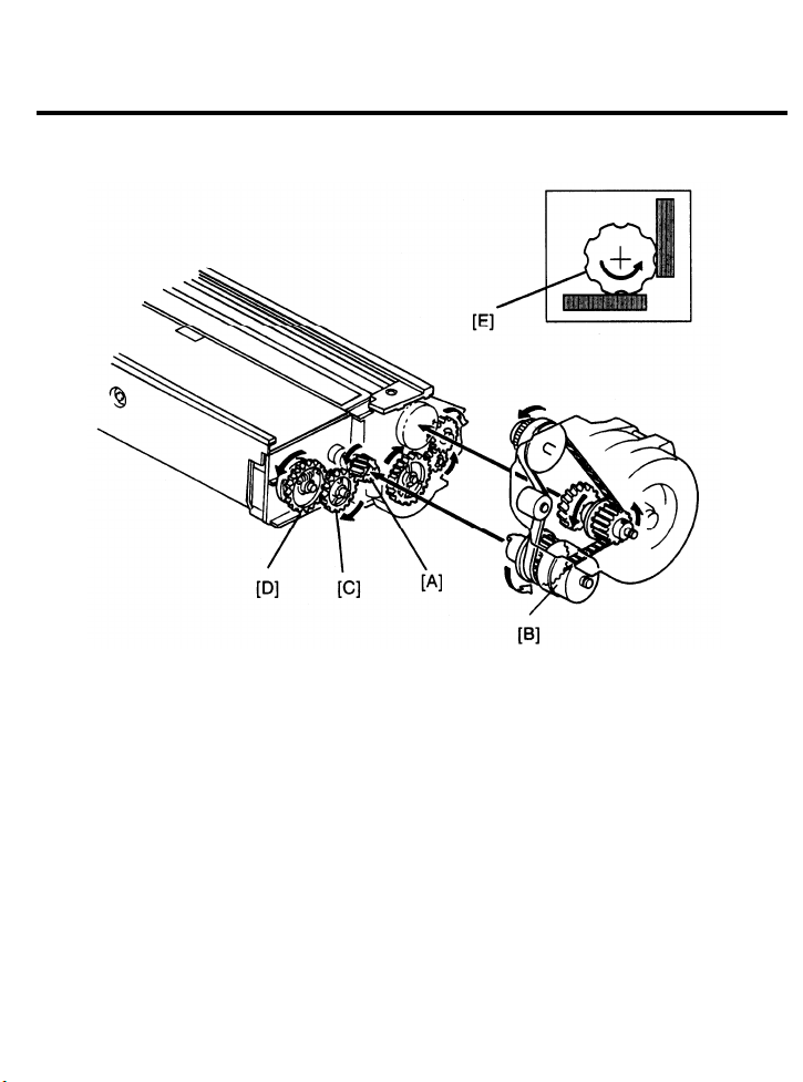
31 August 1989
6. TONER DENSITY DETECTION AND TONER SUPPLY
6.1 TONER SUPPLY
The toner supply drive gear [A] turns when the development motor is on. The toner supply
clutch [B] applies the rotation from the toner supply drive gear to the toner supply roller gear
[C], which drives the agitator gear [D]. Toner catches in the grooves on the toner supply
roller [E]. Then, as the grooves turn past the opening, the toner drops into the development
unit.
The teeth on both the toner supply drive gear and the toner supply roller gear are chamfered.
2-38
Page 87

6.2 BOTTLE DRIVE MECHANISM
31 August 1989
For easy access, the toner bottle is just inside the front cover. The bottle is positioned
horizontally.
The bottle drive mechanism transports toner from the bottle to the toner tank. A worm gear
[A] on the front end of the toner supply roller [B] drives this mechanism.
When the toner supply roller turns, the worm gear turns the toner bottle [C] via the worm
wheel, the bottle drive gear, and the bottle gear. The toner bottle has a spiral groove that
helps move toner to the toner inlet.
To prevent toner from scattering when the toner bottle is lowered, a rack [D] and pinion [E]
system closes the toner shutter [F].
At the toner inlet section, the toner agitator [G] has a spiral shape to move the toner to the
toner tank cavity.
2-39
Page 88

31 August 1989
6.3 TONER DENSITY DETECTION
E: Full Erase
F: ID Check
G: Edge Erase (copy cycle)
H: Low Toner Condition
I: Enough Toner Condition
J: Sensor Pattern Image
The main CPU checks the image density of the sensor pattern at the beginning of the first
copy cycle (after the main switch is turned on) and at every tenth copy cycle.
Alter the sensor pattern [A] is developed, the image density sensor [B] (a photosensor)
checks its reflectivity. If the reflected light is too strong, the CPU determines that the toner
density is too low. It then adds toner to the development unit.
Toner is not added all at once. The CPU energizes the toner supply clutch to add a selected
amount of toner over the next 10 cycles.
2-40
Page 89

31 August 1989
6.4 TONER DENSITY CONTROL
The image density sensor checks the density of the sensor pattern image once every 10 copy
cycles. The CPU receives two voltage values directly from the sensor: the value for the bare
drum (Vsg) and the value for the sensor pattern image (Vsp). These two values are then
compared to determine whether or not more toner should be added.
High image density (no toner added)
2. Vsp > 1/8 of Vsg . . . . . . . .
Low image density (toner is added)
When the image density is too low (Vsp > 1.5 volts), the CPU changes from the detect mode
to fixed toner supply mode. It will be recovered when VSP becomes less than 1.5 volts
automatically. If Vsg becomes less than 2.5 volts, the CPU determines that the sensed data is
abnormal, then it stops any further toner supply to the development tank. However, toner
supply is re-established if Vsg becomes greater than 2.5 volts. In either case the service call
indicator will blink.
SP mode #54 turns on the LED sensor manually. VR1 on the ID sensor board adjusts the
intensity of the sensor LED (the voltage of Vsg).
SP mode #55 displays Vsp and Vsg voltage values.
2-41
Page 90

31 August 1989
6.5 TONER SUPPLY AMOUNT
This copier has two different ways of controlling the amount of toner supplied. Normally, the
detect supply mode system is used to control toner supply. However, a fixed supply system
can also be selected using SP #30.
SP #30
Toner supply mode
0
Detect
1
Fixed
Toner supply starts 43 pulses after the exposure lamp turns off. Toner is supplied at this time
to prevent toner scattering on the copies. The amount of toner added depends on the size of
copy paper being used.
2-42
Page 91

31 August 1989
Detect Supply Mode
In the detect supply mode (SP#30 set to zero), when a low toner image density condition is
detected (Vsp > 1/8 Vsg), toner is supplied during each copy cycle for the next ten copies as
determined by SP #32 (toner supply amount --
fixed and detect modes). If Vsp becomes
greater than 4/25 of Vsg, the CPU adds toner as determined by SP #31 (detect mode). If Vsp
becomes greater than 1/4 of Vsg (Vsp > 1/4 Vsg), the toner supply amount changes to 60%
regardless of those SP settings. If Vsp becomes greater than 1.5 volts and the CPU detects
this condition 3 times, the wrench mark starts blinking on the operation panel board. The toner
supply amount in this condition remains 60% of the detect toner supply mode.
1 2 3
SP #31
Toner Supply
0
30% 15% 45% 60%
Amount
Note:
= 4.0 volts
Vsg
1/4 Vsg
4/25 Vsg
1/8 Vsg
3/8 Vsg
= 1.0 volts
= 0.64 volts
= 0.50 volts
= 1.5 volts
Fixed Supply Mode
In the fixed supply mode (SP #30 set to 1), a fixed amount of toner is added every copy as
determined by the setting of SP #32. There is no overtoning detection mechanism.
SP #32
Toner Supply
0 1 2 3
7% 4%
11% 14%
Amount
2-43
Page 92

31 August 1989
6.6 TONER END DETECTION
Sufficient Toner Condition:
The toner end detection mechanism actuates the toner end sensor [A] when the toner tank is
almost empty (60 to 100 grams remaining).
In the first figure, there is enough toner in the toner tank. The toner resists the movement of
the toner agitator [B] and the drive spring [C] stretches. As a result the flat surface of the toner
agitator cam [D] does not align with the flat section of the agitator gear [E], and the actuator is
held in the toner end sensor slit.
The second figure shows what happens if there is not enough toner in the tank. In this case,
the toner does not resist the movement of the agitator; therefore, the agitator gear spring
forces the flat surface of the agitator drive cam to align with the flat surface of the toner
agitator gear. When the flat section comes to the actuator, a spring pulls the actuator out of
the toner end sensor and the sensor sends a toner end signal to the CPU. This starts the
toner end run, which allows 50 copies to be made before the Start key turns red.
2-44
Page 93

31 August 1989
6.7 TONER OVERFLOW SENSOR CIRCUIT
The toner overflow sensor signals the CPU when the toner collection bottle is full.
A tiny tuning fork is used as the sensing element for the toner overflow sensor. This tuning
fork is a damping element in a multivibrator circuit. As long as there is nothing in contact with
the tuning fork, the oscillating frequency of the circuit stays LOW and the transistor stays off.
When toner presses against the tuning fork, the resistance of the piezoelectric elements that
are in contact with the tuning fork changes and the oscillating frequency increases. The
frequency detection circuit passes the higher frequency signal to the rectifier which activates
the switching transistor. The transistor sends a LOW signal to CN103-7 on the main board.
When the CPU receives this LOW signal, it signals the copier to stop, lights the Used Toner
Bottle indicator, and blinks the Service Call indicator. Also, a message instructing the
customer to call for service is displayed on the guidance display.
2-45
Page 94

31 August 1989
7. IMAGE TRANSFER AND PAPER SEPARATION
7.1 PRE-TRANSFER LAMP (PTL)
After the latent image is developed but before the image is transferred to the copy paper, the
drum surface is illuminated by the pre-transfer lamp [A]. This illumination reduces the positive
potential on the drum surface. This is to prevent the toner particles transferred to the paper
surface from being reattracted to the positively charged drum during the paper separation
process. It also makes image transfer and paper separation easier.
2-46
Page 95

31 August 1989
7.2 IMAGE TRANSFER
The registration rollers [A] feed the copy paper through the transfer entrance guide to the
transfer section. A high positive voltage is applied to the transfer corona wire [B], and the
corona wire generates positive ions. These positive ions are applied to the reverse side of the
paper, and the paper is electrostatically attracted to the drum surface. This is due to the
relationship between the following three attractive forces:
A1: Paper and Toner
The attraction between the positively charged paper [C] and the negatively charged toner.
A2: Paper and Drum (Aluminum core)
The attraction between the positively charged paper and the negative countercharge on
the aluminum core of the drum.
A3: Toner and Drum (Selenium layer)
The attraction between the positively charged drum and the negatively charged toner.
2-47
Page 96

31 August 1989
Since the positive force applied to the reverse side of the paper by the transfer corona is much
greater than the strength of the positive ions on the drum surface, A1 is greater than A3, and
A2 is greater than A3.
A1 > A3
A2 > A3
Transfer occurs
2-48
Page 97

31 August 1989
7.3 PAPER SEPARATION
A1 > A2 > A3 –> Separation occurs
After image transfer, the paper is fed to the separation section. This process separates the
paper from the drum while holding the toner on the paper surface.
Ac and dc currents are applied to the separation corona wire, and the corona wire generates
ions. These positive ions are applied to the reverse side of the paper, breaking the attractive
forces A2 and A3; however, A1 is not broken. The paper separates from the drum taking the
toner with it.
2-49
Page 98

31 August 1989
7.4 TRANSFER/SEPARATION CORONA POWER PACK
The power pack has a dc-to-dc converter and a dc-to-ac inverter.
The dc-to-dc converter changes +24 volts (Vp) to 5.78 kilovolts dc for the transfer corona.
The inverter changes +24 volts (Vp) to 6.2 kilovolts ac with a slight negative dc bias for the
separation corona. Both coronas turn on when the CPU applys a LOW at CN101-A21.
The main board sends a LOW trigger signal to the TC/SC power pack when the lead edge of
the paper turns on the registration sensor. The TC/SC power pack turns off 328 milliseconds
after the trailing edge of the copy paper deactuates the registration sensor.
2-50
Page 99

31 August 1989
The separation corona current is not always constant. It has two levels--a lead edge level and
the normal level. The normal separation corona current has an ac value of about 200
micro-amperes with little dc component. However, at the leading edge, the dc value is
reduced from about -2.5 micro-amperes to a dc component of about -8 micro-amperes. This
helps the leading edge of the paper separate from the drum. This is accomplished by the CPU
supplying a LOW signal at CN101-21B to the TC/SC power pack. (The above values for the
drum currents are theoretical calculations for total drum current.)
Normally, the lead edge separation corona current is applied to the first 10 millimeters of the
copy paper. However, you can select a margin of 7 or 13 millimeters using SP mode #37.
#37
0
1
2
Margin
10 mm
7 mm
13 mm
2-51
Page 100

31 August 1989
7.5 PICK-OFF MECHANISM
Touch-and-Release Mechanism
The pick-off solenoid [A] energizes just after the registration rollers turn on. The pick-off lever
[B] rotates counterclockwise (rear view) and pushes the pawl shaft pin [C]. The pawl shaft [D]
then rotates clockwise and the pick-off pawls [E] touch the drum. The pawl springs [F] hold
the pick-off pawls on the shaft and prevent them from touching the drum too strongly.
When the leading edge of the paper passes the pick-off area and just before it reaches the
fusing unit, the pick-off solenoid turns off. The pick-off shaft spring [G] then rotates the
pick-off lever and moves the pick-off pawls away from the drum.
Side-to-Side Movement
The pick-off pawls do not always contact the drum in the same place but instead move slightly
to the side on each copy cycle.
The pick-off pawl shaft [H] and the cam rider [I] are joined by a one-way bearing [J]. Each
time the pick-off pawl solenoid turns on, the one-way bearing causes the cam rider to turn
together with the pick-off pawl shaft. As the cam rider turns, it and the pawl shaft are forced to
move laterally by a cam [K]. When the pawl shaft rotates the pawls away from the drum,
however, the cam rider does not turn.
Pawl lateral movement is 0.1 to 0.2 millimeter per copy cycle. After moving about 8
millimeters, the cam rider passes the lobe of the cam and the pawl shaft is returned to its start
position by the pawl shaft spring [G].
2-52
 Loading...