


PAPER TRAY UNIT
(Machine Code: A325/A326)

12 February 1992 SPECIFICATION
1. SPECIFICATION
Configuration: 1 tray type table or 3 tra y ty pe tab l e
Copy Paper Size: Maximum A3/11"X17"
Minimum B5/8
Copy Paper Weight: 52 - 128g/m2, 14 - 34lb.
Copy Paper Capacity: Approximately 250 sheets
Paper Feeding Speed: [Main frame: A069/A073/A074 copier]
33 copies/minute (A4/8
19 copies/minute (A3)
18 copies/minute (11"X17")
Power source: Dc 24V, 5V from the main frame
Drive Source: Driven by the main frame through gear
engagements
1/2
"X11"
"X11" sideways)
1/2
Power Consumption: Maximum 20W
Average 15W
Dimensions: 680mm/26.8"(width) X 430mm/16.9"(depth) X
600mm/23.6"(height)
Weight: Less than 38kg/83.8lb. (1 tray type)
Less than 45kg/99.2lb. (3 tr ay typ e)
Unit
Paper Tray
1
COMPONENT LAYOUT 12 February 1992
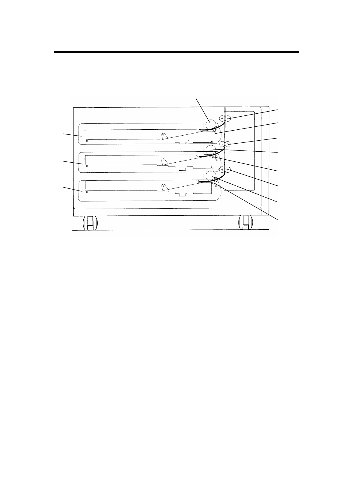
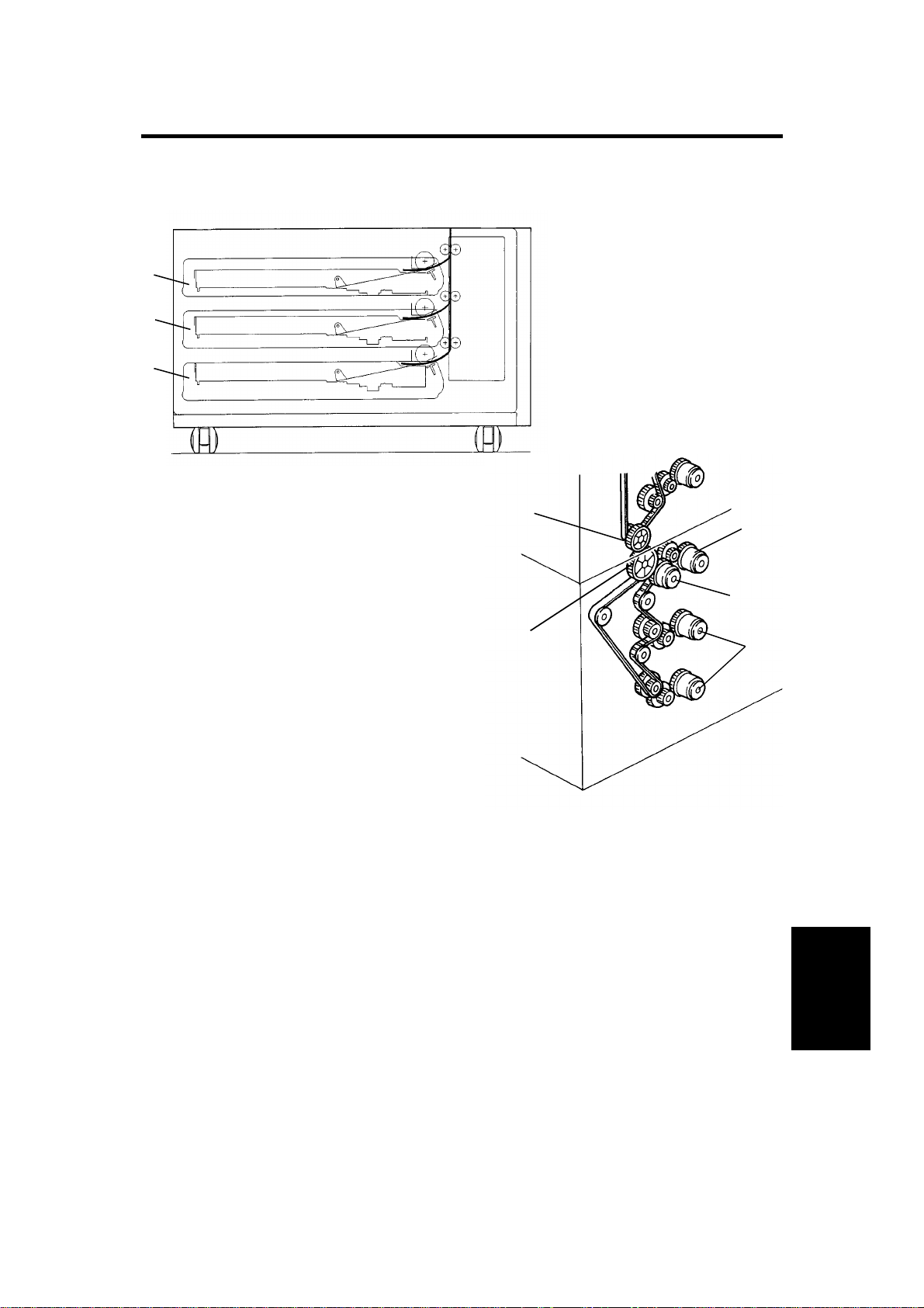
2. COMPONENT LAYOUT
2.1 MECHANICAL COMPONENT LAYOUT
1
2
3
12
11
10
1. Paper Feed Roller (Paper Tray 1)
2. Tray Relay Rollers -1
3. Friction Pad (Paper Tray 1)
4
5
6
7
8
9
7. Tray Relay Rollers -3
8. Paper Feed Roller (Paper Tray 3)
9. Friction Pad (Paper Tray 3)
4. Tray Relay Rollers -2
5. Paper Feed Roller (Paper Tray 2)
6. Friction Pad (Paper Tray 2)
10. Paper Tray -3
11. Paper Tray -2
12. Paper Tray -1
2
12 February 1992 COMPONENT LAYOUT
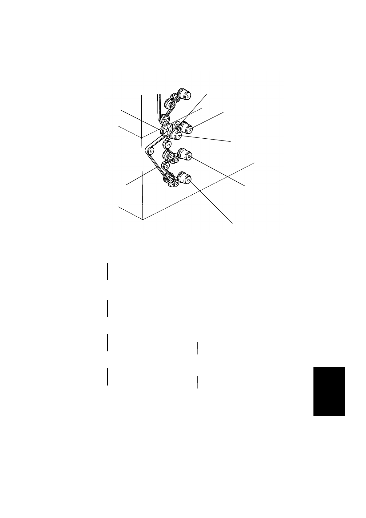
2.2 DRIVE LAYOUT
2
1
7
1. Tray Unit
Driven Gear
4: Tray Unit Drive
CL Gear
3
4
5
6
2: Paper Feed
Drive Gear
7: Tray Drive
Belt
5: Paper Feed CL-2
Gear
3: Paper Feed
CL-1 Gear
6: Paper Feed CL-3
Gear
3
Unit
Paper Tray

COMPONENT LAYOUT 12 February 1992
2.3 ELECTRICAL COMPONENT DESCRIPTION
Refer to the electrical component layout on the reverse side of the Point to
Point (water proof paper ) for symbols and index numbers.
Symbol Name Function Index No.
Motors
M1 Tray lift - 1 Raises the bottom plate in paper tray - 1. 8
M2 Tray lift - 2 Raises the bottom plate in paper tray - 2. 30
M3 Tray lift - 3 Raises the bottom plate in paper tray - 3. 28
Circuit board
PCB1 Tray control Controls the paper tray functions according
to the signal from the copier main board.
Switches
SW1 Tray 1 : Paper
size - 1
SW2 Tray 1 : Paper
size - 2
SW3 Tray 1 : Paper
size - 3
SW4 Tray 1 : Paper
size - 4
SW5 Tray 2 : Paper
size - 1
SW6 Tray 2 : Paper
size - 2
SW7 Tray 2 : Paper
size - 3
Determines what size paper is in the paper
tray - 1.
Determines what size paper is in the paper
tray - 1.
Determines what size paper is in the paper
tray - 1.
Determines what size paper is in the paper
tray - 1.
Determines what size paper is in the paper
tray - 2.
Determines what size paper is in the paper
tray - 2.
Determines what size paper is in the paper
tray - 2.
17
1
3
6
9
38
4
7
SW8 Tray 2 : Paper
size - 4
SW9 Tray 3 : Paper
size - 1
Determines what size paper is in the paper
tray - 2.
Determines what size paper is in the paper
tray - 3.
4
11
2

12 February 1992 COMPONENT LAYOUT
Symbol Name Function Index No.
SW10 Tray 3 : Paper
size - 2
SW11 Tray 3 : Paper
size - 3
SW12 Tray 3 : Paper
size - 4
SW13 Tray unit door – 1 Detects if the tray unit door is open or not. 32
SW14 Tray unit door – 2 Cuts the dc 24 V line for the tray unit drive
Magnetic clutches
MC1 Paper feed - 1 Starts paper feed from paper tray 1. 14
MC2 Paper feed - 2 Starts paper feed from paper tray 2. 16
MC3 Paper feed - 3 Starts paper feed from paper tray 3. 18
MC4 Tray unit drive Drives the rollers in the paper tray. 13
Determines what size paper is in paper tray
- 3.
Determines what size paper is in paper tray
- 3.
Determines what size paper is in paper tray
- 3.
clutch when the tray unit door is open.
5
31
27
34
Solenoids
SOL1 Tray lock - 1 Locks paper tray 1 in the paper tray unit. 40
SOL2 Tray lock - 2 Locks paper tray 2 in the paper tray unit. 39
SOL3 Tray lock - 3 Locks paper tray 3 in the paper tray unit. 37
Sensors
S1 Tray set - 1 Detects if paper tray 1 is set or not. 15
S2 Tray set - 2 Detects if paper tray 2 is set or not. 21
S3 Tray set - 3 Detects if paper tray 3 is set or not. 22
S4 Tray upper limit -1Detects the upper position of the paper
stack in paper tray 1 to stop tray lift motor 1.
S5 Tray upper limit -2Detects the upper position of paper stack in
the paper tray 2 to stop tray lift motor 2.
10
29
Unit
Paper Tray
5

COMPONENT LAYOUT 12 February 1992
Symbol Name Function Index No.
S6 Tray upper limit -3Detects the upper position of the paper
stack in paper tray 3 to stop tray lift motor 3.
S7 Paper end - 1 Informs the copier CPU when paper tray 1
runs out of paper.
S8 Paper end - 2 Informs the copier CPU when paper tray 2
runs out of paper.
S9 Paper end - 3 Informs the copier CPU when paper tray 3
runs out of paper.
S10 Tray relay - 1 Detects the lead edge of paper from paper
tray 1 to determine the stop timing of paper
feed clutch 1 and detects misfeeds.
S11 Tray relay - 2 Detects the lead edge of paper from paper
tray 2 to determine the stop timing of paper
feed clutch 2 and detects misfeeds.
S12 Tray relay - 3 Detects the lead edge of paper from the
paper tray 3 to determine the stop timing of
paper feed clutch 1 and detects misfeeds.
26
12
19
20
25
24
23
Heaters
H1 Tray - 1 (option) Turns on when the main switch is off to
keep paper dry in paper tray 1.
H2 Tray - 2 (option) Turns on when the main switch is off to
keep paper dry in paper tray 2.
H3 Tray - 3 (option) Turns on when the main switch is off to
keep paper dry in paper tray 3.
36
35
33
6
12 February 1992 OVERVIEW
3. OVERVIEW
[A]
[A]
[A]
[B]
[E]
[D]
[C]
There are two types of paper t ray un it: one tray and three tray types. Each
paper tray [A] is a drawer type and their function and mechanism are exactly
the same as those of the main frame .
All the electrical components of the pape r tray are controlled by the copier
main control board through the tray control board.
All the tray rollers are driven by the m ain fram e via the tr ay un it dr ive and
driven gears [B,C]. When the tray unit drive clutch [D] is energ i zed, the drive
is transmitted to the paper tray unit and the relay rollers start rotating. When
the paper feed clutch [E] for the selected paper tray is energized, paper is fed
from the paper tray to the ma in frame through the relay rollers.
[E]
Unit
Paper Tray
7

INSTALLATION 12 February 1992
4. INSTALLATION
4.1 ACCESSORY CHECK
Check the quantity and conditio n of the accesso r ies in th e box according to
the following list:
1. Harness Bracket ...................................................................1
2. Harness Clamp ......................................................................1
3. Philips Pan Head Screw –M4 x 8 ..........................................2
4. Screw –M4 x 8........................................................................2
5. Shoulder Screw –M3..............................................................1
6. Shoulder Screw –M4..............................................................1
7. Rubber Ring ........................................................................... 1
8. Tray Decals .................. .......................................................... 1
9. New Equipment Condition Report
(–17, –27 machines only) ....................................................... 1
10. Envelope for N.E.C.R.
(–17 machine only) ................................................................ 1
11. Installation Procedure ...........................................................1
8

12 February 1992 INSTALLATION
4.2 INSTALLATION PROCEDURE
[C]
[A]
[B]
[A]
[A]
[E]
[F]
[D]
[F]
CAUTION: Unplug the copier power cord before starting the following
procedure.
NOTE: Keep the shipping retainers after installing the machine. They will be
roused if in the future the machine is transported to an another
location.
Proper reinstallation of th e ship pin g ret ain er s is required in order to
avoid any transport da mage.
1. Remove the strips of tape [A]. (3 tray type: 4 strips, 1 tray type: 2 strips).
2. Remove the accessory bag [B] (1 tape).
3. Pull out the paper tray and remove a strip of tape and the foam block. Do
this for all the paper trays.
4. Set the copier [C] onto the pape r tray unit [D]. Align the 2 pins [E] of the
paper tray unit with the holes in the base plate of the copier. At this time
each side of the copier and paper tray unit will align with one another [F].
9
Unit
Paper Tray

INSTALLATION 12 February 1992
[A]
[A]
[B]
[D]
[C]
5. Fix the copier on the paper tray unit with 2 screws [A].
6. Remove the copier rear cover [B] (Remove 2 screws and loos en 2
screws) and paper tray unit rear cover [C] (remove 1 screw and loosen 2
screws).
7. Remove the shield plate [D] (1 screw) from the copier harness bracket.
10

12 February 1992 INSTALLATION
[B]
[F]
[G]
[E]
[G]
[F]
[A]
[B]
[E]
[D]
[C]
[F]
[H]
[G]
8. Remove the screw [A] for the connecting gear bracket [B].
9. Remove one screw [C] and loosen another screw [D] to let the gear fixing
bracket [E] rotate down.
10. Engage the paper t ray dr iven gear [F] with the paper tr ay dr ive gear [G]
by raising the connecting gear bracket.
11. Secure the gear fixing bracket with the screws [C] and [D] on the shaf ts of
the paper tray drive ge ar an d th e paper tray driven gear.
12. Fix the connecting gear bracket (1 shoulder screw –M3 [F] and 1
shoulder screw –M4 [G] with rubber ring [H]).
Unit
Paper Tray
11

INSTALLATION 12 February 1992
[C]
[E]
[D]
[A]
[B]
[F]
[G]
13. Set the wire saddle [A] on the harness bracket [B] and position the paper
tray harness [C] and the tray heater harness [D] in the wire saddle.
14. Install the harness bracket [B] as shown (2 screws).
NOTE: Make sure that the screws are firmly secured so that the
protective earth between the copier and the paper tray unit is
maintained.
15. Couple the connector [E] of the tray heater ha rness with the copier and
couple the connectors of the paper tray harness with the following
connectors of the copier main control board:
11p connector [F] ......................CN112
8p connector [G] ......................CN113
16. Follow the copier installatio n pro c ed ure.
12

12 February 1992 INSTALLATION
[A]
17. Reinstall all the covers.
18. While pressing both "1" and "3" on the operation panel number keys, turn
on the main switch in order to access the SP mode.
NOTE: Release the number keys afte r conf ir mi ng tha t th e call ser vice
indicator and the copy coun ter number "0" are blinkin g.
19. Enter "72" using the number keys and then press the enter key.
20. Enter "1" using the number keys and then press the enter key.
21. Turn off the main switch.
22. Stick the tray decals [A] on the appropriate paper trays.
23. Turn on the main switch and check the machine operation and copy
quality.
Unit
13
Paper Tray

INSTALLATION 12 February 1992
TRAY HEATER INSTALLATION (OPTION)
[A]
[C]
[D]
NOTE: The optional tray heaters keep copy paper dry. In humid
environments, copy paper may crease as it comes out of the
fusing unit. The heaters are available as service parts.
Required parts:
Part Number Description
A0699500 Tray Heater Kit –115V 3 sets 1 set
A0699501 Tray Heater Kit –230V 3 sets 1 set
The contests of the kits
are as follows:
Tray heater 1 piece
Tray heater bracket 1 piece
Wire saddle 1 piece
Philips pan head screw 3 pieces
Decal: High Temp. 1 piece
3-Tray
Type
[B]
1-Tray
Type
CAUTION: Unplug the copier power cord before starting the following
procedure.
1. Open the paper tray front door [A].
2. Pull out the paper tray [B] and remove the tray stopper brackets [C], [D]
on both sides as shown (1 screw each) and th en rem ove the pap er tr a y
from the paper tr ay un it ( 3 pa pe r tr ays for 3 tray type).
14

12 February 1992 INSTALLATION
[G]
[F]
[E]
[B]
[D]
[C]
[F]
[H]
[A]
[I]
3. Remove the paper tray unit rear cover [A](remove 1 screw and loos en 2
screws).
NOTE: Repeat steps 4 to 6 three times for the 3–tray type.
4. Fix the tray heater [B] on the tray heater bracket [C] (2 screws), and set
the wire saddle [D] and the heater harne ss [E] on th e bracket as shown.
5. Pass the heater harness thro ug h the heater access hole [F] and the wir e
saddle [G] and install the tray heater assembly as shown (1 screw at the
front).
6. Connect the heater connect or [H] with th e paper tray unit as shown (2P
red).
7. Stick the warning: High temp. decal [I] on the plate, to the right of the tray
heater bracket as shown.
8. Reassemble the paper tray unit.
9. Tell the customer that the copier main switch should be turned off and the
power cord should not be unplugged at night. Otherwise, the tray heaters
will not function.
Unit
Paper Tray
15

SERVICE TABLE 12 February 1992
5. SERVICE TABLE
5.1 SERVICE REMARKS
1. Do not touch the pick-up, feed, sepa r at i on roller s an d the friction pads
with oily bare hands.
2. The side fences and the rear fen ce of t he pap er tr a ys shou ld be
positioned correctly to align with the actual paper size. Otherwise, paper
misfeeds may occur.
3. The friction pad should be replaced together with the friction pad holder
and pad entrance seal as an assembly.
4. The friction pad assembly and the paper feed roller should be replaced
as a set to maintain paper feed ability. (A worn out feed roller will provide
incorrect friction pad pressure.)
5. The friction pad holder mounting bracket must be reinstalled on the
original paper tray. Because the friction pad pressure is adjust ed for ea ch
paper feed station independently at the factory.
6. The paper tray with the frictio n pad m ech an ism must be re inst alled at the
original paper feeding statio n.
7. The friction pad pressure should not be adjusted in the field.
16

12 February 1992 SERVICE TABLE
5.2 PM TABLE
PAPER TRAY UNIT (A325/A326)
EM 80K 160K 240K NOTE
Paper Feed Roller C R R R
Friction Pad Ass’y C R/L R/L R/L
Paper Tray Bottom Plate
Pad
Drive Belt I I I Replace if necessary
Bushings L Spindle oil
R R R Water
Water, Replace with friction pad
ass’y as a set.
Water/Albania 2 grease
Refer to NOTE 1
Refer to NOTE 2
[A]
NOTE 1: Friction Pad Assembly
Replace the friction pad assembly [A] every 80k. Then, lubricate
the pad holder with ALBA MI A 2 gr ea se as shown.
NOTE 2: Relay Rollers and Tray Paper Feed
17
Unit
Paper Tray

REPLACEMENT AND ADJUSTMENT 12 February 1992
6. REPLACEMENT AND ADJUSTMENT
6.1 PAPER TRAY REMOVAL
[A]
[C]
[B]
[D]
1. Open the paper tray unit door [A].
2. Pull out the paper tray [B] and remove the tray stopper brackets [C, D] on
both sides as shown (1 screw each) and then remove the pap er tray from
the paper tray unit.
NOTE: When removing several paper trays at a time, make sure that the
paper tray is returned to the or igin al fe ed ing station. To identify
the original feeding station, each paper tray has its own decal on
the right side.
C: Paper Tray Unit - Tray 1
D: Paper Tray Unit - Tray 2
E: Paper Tray Unit - Tray 3
18

12 February 1992 REPLACEMENT AND ADJUSTMENT
6.2 PAPER FEED ROLLER REPLACEMENT
NOTE: Replace the paper feed roller and the friction pad assembly as a set
to maintain paper feeding ability.
(1) Feed Roller Replacement
[C]
1. Remove the paper tray (see Paper Tray Removal).
[D]
[B]
[A]
2. Remove the feed roller guide [A] (1 screw).
3. Remove the feed roller assembly [B] from the shaft [C].
4. Replace the feed roller hub [D] f rom th e old to th e ne w f eed r olle r.
NOTE: When replacing the feed roller hub, make sure that the
projections of the hub engage with the grooves of the feed roller.
5. Reassemble the copier.
19
Unit
Paper Tray

REPLACEMENT AND ADJUSTMENT 12 February 1992
(2) Friction Pad Replacement
[B]
[D]
[C]
[A]
1. Pull out the paper tray.
2. Remove the friction pad holder mounting bracket [A] from th e pa pe r tray
(2 screws with washer).
3. Unhook the spring [B] from the pressure release lever.
4. Remove the friction pad assembly [C] fr om the mounting bracket (1 screw
and 1 swivel bushing).
5. Lubricate the sliding surface [D] of the new friction pad assembly slightly
with the grease "Albania 2".
6. Install the new friction pad assem bly on the mounting bracket and
reassemble the paper tray.
NOTE: If the friction pad assembly is replaced for seve r al paper trays at a
time, make sure that the friction pad holder mounting bracket is
placed back to the original paper tray.
To identify the original position, the mounting bracket and the paper
tray have the identical decals such as "C", "D", "E".
20

12 February 1992 REPLACEMENT AND ADJUSTMENT
6.3 TRAY UNIT DRIVE AND PAPER FEED CLUTCH
REPLACEMENT
[A]
[C]
[B]
[D]
[A]
[F]
1. Remove the copier and tray unit rear covers.
2. Remove the harness bracket [A] (2 screws).
NOTE: When reinstalling the bracket, make sure that the screws are
firmly secured so that the protective earth between the copier
and the paper tray unit is maint ained.
3. Remove the bearing holder bracket [B] (1 screw).
4. Remove the tray unit drive clutch [C ] (1 E- ri n g an d 1 con ne cto r ) .
NOTE: When reinstalling the clutch, make sure that the clutch stopper
groove [D] engages with the stopper.
5. Remove the stopper bracket [E] (1 screw).
6. Remove the paper feed clutch [F] (1 connector and 1 wire saddle).
NOTE: When reinstalling the clutch, make sure that the clutch stopper
pin [G] engages with the groove of the stopper bracket.
Unit
Paper Tray
21

REPLACEMENT AND ADJUSTMENT 12 February 1992
6.4 TRAY LIFT MOTOR REPLACEMENT
[C]
[A]
[B]
[A]
1. Remove the tray rear cover (remove 1 screw and loosen 2 screws).
= 1 tray type =
2. Remove the tray lift motor [A] (2 screws and 1 connector).
= 3 tray type =
3. Remove the paper tray from the paper tray unit (see paper tray removal).
4. Remove the tray set sensor bracket [B] (1 screw and 1 connector).
5. Pull out the paper lift motor asse m bly [C] fr om th e pa pe r tr ay un it (2
screws, 2 connectors, and 1 wire clam p ).
6. Remove the tray lift motor [A] (2 screws).
22

12 February 1992 REPLACEMENT AND ADJUSTMENT
Table of Contents
SPECIFICATION 1
COMPONENT LAYOUT 2
MECHANICAL COMPONENT LAYOUT 2
DRIVE LAYOUT 3
ELECTRICAL COMPONENT DESCRIPTION 4
OVERVIEW 7
INSTALLATION 8
ACCESSORY CHECK 8
INSTALLATION PROCEDURE 9
SERVICE TABLE 16
SERVICE REMARKS 16
PM TABLE 17
REPLACEMENT AND ADJUSTMENT 18
PAPER TRAY REMOVAL 18
PAPER FEED ROLLER REPLACEMENT 19
TRAY UNIT DRIVE AND PAPER FEED CLUTCH REPLACEMENT 21
TRAY LIFT MOTOR REPLACEMENT 22
23
Unit
Paper Tray
 Loading...