

Page 1

IMPORTANT SAFETY NOTICES
PREVENTION OF PHYSICAL INJURY
1. Before disassembling or assembling parts of the copier and peripherals,
make sure that the copier power cord is unplugged.
2. The wall outlet should be near the copier and easily accessible.
3. Note that some components of the copier and the paper tray unit are
supplied with electrical voltage even if the main switch is turned off.
4. If any adjustment or operation check has to be made with exterior
covers off or open while the main switch is turned on, keep hands away
from electrified or mechanically driven components.
5. If the start key is pressed before the copier completes the warm-up
period, keep hands away from the mechanical and the electrical
components as the copier starts making copies as soon as the warm-up
period is completed.
6. The inside and the metal parts of the fusing unit become extremely hot
while the copier is operating. Be careful to avoid touching those
components with your bare hands.
HEALTH SAFETY CONDITIONS
1. Toner and developer are non-toxic, but if you get either of them in your
eyes by accident, it may cause temporary eye discomfort. Try to remove
with eye drops or flush with water as first aid. If unsuccessful, get
medical attention.
OBSERVANCE OF ELECTRICAL SAFETY STANDARDS
1. The copier and its peripherals must be installed and maintained by a
customer service representative who has completed the training course
on those models.
2. The RAM board on the main control board has a lithium battery which
can explode if replaced incorrectly. Replace the battery only with an
identical one. The manufacturer recommends replacing the entire RAM
board. Do not recharge or burn this battery. Used batteries must be
handled in accordance with local regulations.
Page 2

SAFETY AND ECOLOGICAL NOTES FOR DISPOSAL
1. Do not incinerate the toner bottle or the used toner. Toner dust may
ignite suddenly when exposed to open flame.
2. Dispose of used toner, developer, and organic photoconductor
according to local regulations. (These are non-toxic supplies.)
3. Dispose of replaced parts in accordance with local regulations.
4. When keeping used lithium batteries in order to dispose of them later,
do not put more than 100 batteries per sealed box. Storing larger
numbers or not sealing them apart may lead to chemical reactions and
heat build-up.
Page 3

A204/A206/A207/A208/A210/A211
COPIER
SERVICE MANUAL
The A204 copier is based on the A153 copier.
The A206 copier is based on the A155 copier.
The A207 copier is based on the A156 copier.
The A208 copier is based on the A157 copier.
The A210 copier is based on the A159 copier.
The A211 copier is based on the A160 copier.
Only the differences from the base copiers are described in the
following pages. Therefore, this documentation should be treated
as an insert version of the base copier’s service manual, although
it has a separate binder. It should always be utilized together with
the base copier’s service manual.
Page 4

31 March 1997 SPECIFICATIONS
1. SPECIFICATIONS
NOTE:
Only items marked with ✽ are different from A153, A155, A156,
A157, A159, and A160 copiers.
Configuration: Desktop
Copy Process: Dry electrostatic transfer system
Originals: Sheet/Book
Original Size: Maximum: A3/11" x 17"
Copy Paper Size: Maximum: A3/11" x17" (Paper trays)
Minimum: A5/8
A4/11" x 8
A6/5
1/2
1/2
" x 5
" x 8
1/2
" sideways (Paper trays)
1/2
" sideways (LCT)
1/2
" lengthwise (By-pass)
Duplex Copying: Maximum: A3/11" x 17"
Minimum: A5/8
1/2
✽ Copy Paper Weight: Paper tray: 52 ~ 128 g/m
By-pass: 52 ~ 157 g/m
LCT: 52 ~ 128 g/m
Duplex copying: 64 ~ 105 g/m
" x 5
1/2
" (sideways)
2
, 14 ~ 34 lb
2
, 14 ~ 42 lb
2
, 14 ~ 34 lb
2
, 17 ~ 24 lb
Copier
Reproduction Ratios: 4 Enlargement and 6 Reduction
A4/A3 Version LT/DLT Version
200%
Enlargement
Full size 100% 100%
Reduction
141%
122%
115%
93%
82%
75%
71%
65%
50%
200%
155%
129%
121%
93%
85%
77%
74%
65%
50%
1
Page 5
SPECIFICATIONS 31 March 1997
Power Source: 120 V/60 Hz:
More than 12 A (for North America)
220 V ~ 240 V/50 Hz:
More than 7 A (for Europe)
220 V/50 Hz:
More than 7 A (for Asia)
110 V/60 Hz:
More than 13 A (for Taiwan)
220 V/60 Hz:
More than 7 A (for Saudi Arabia, Philippines)
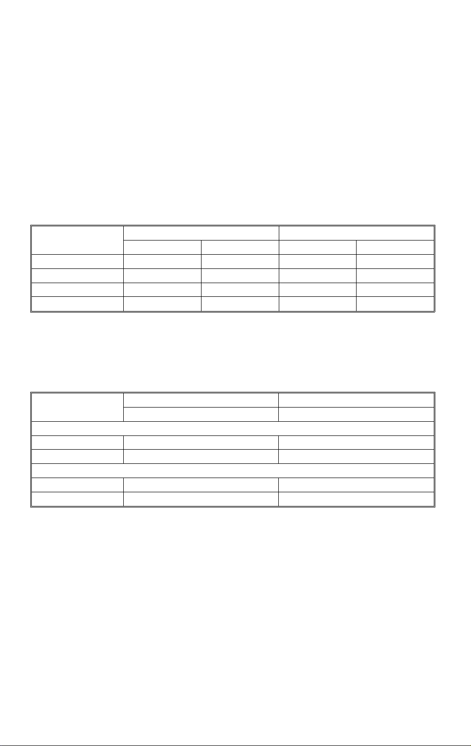
✽ Power Consumption:
A204, A206, and A2 07 copiers A208, A210, and A21 1 copiers
Copier Only Full System Copier Only Full System
Maximum 1.35 kW 1.40 kW 1.35 kW 1.40 kW
Copying 1.15 kW 1.21 kW 0.90 kW 1.00 kW
Warm-up 1.21 kW 1.23 kW 0.98 kW 1.00 kW
Stand-by 0.18 kW 0.20 kW 0.16 kW 0.18 kW
NOTE:
– Full System –
Copier + ARDF (A663) + Paper Tray Unit (A549) + 20 Bin S/S (A664)
✽ Noise Emission:
A204, A206, and A20 7 copiers A208, A210, and A211 copiers
Copier Only Copier Only
1. Sound Pressure Level
Operator position 64 dB (A) 63 dB (A)
Standard positio n 59 dB (A) 58 dB (A)
2. Sound Power Level
Copying 70 dB (A) 69 dB (A)
Stand-by 42 dB (A) 43 dB (A)
NOTE:
The above measurements were made in accordance with ISO 7779.
2
Page 6

31 March 1997 SPECIFICATIONS
Dimensions:
Width Depth Height
A204 copier 1,030 mm (40.6") 655 mm (25.8 ") 606 mm (23.9")
A208 copier 900 mm (35. 5") 655 mm (25.8") 606 mm (2 3.9")
A206 and A207 copiers 1,258 mm (49 .6 ") 655 mm (25.8") 606 mm (2 3.9")
A210 and A211 copiers 1,128 mm (44 .5 ") 655 mm (25.8") 606 mm (2 3.9")
Measurement Conditions
1) With by-pass feed table closed
2) With platen cover and copy tray attached
3) With LCT cover closed
Copier
✽ Weight:
NA EU
A204 copier 70 kg (154.3 lb) 73 kg (160.9 lb)
A206 copier 78 kg (172.0 lb) 81 kg (178.5 lb)
A207 copier 81 kg (178.6 lb) 84 kg (185.2 lb)
A208 copier 69 kg (152.1 lb) 72 kg (158.7 lb)
A210 copier 77 kg (169.8 lb) 80 kg (176.4 lb)
A211 copier 79 kg (174.2 lb) 82 kg (180.7 lb)
Weight
Zoom: From 50% to 200% in 1% steps
✽ Copying Speed (copies/minute):
A4 sideways/
11" x 8
A204, A206, and A207 copiers 40 22/21 25
A208, A210, and A211 copiers 32 17/16 19
1/2
"
A3/11" x 17" B4/8
✽ Warm-up Time: A204, A206, and A207 copiers:
Less than 250 seconds (20°C)
A208, A210, and A211 copiers:
Less than 110 seconds (20°C)
" x 14"
1/2
✽ First Copy Time:
Paper Feed Station
1st Tray 4.4 s (except for A20 7) 4.9 s (except for A211)
2nd Tray 4.9 s 5.4 s
By-pass 4.4 s 4.7 s
LCT 4.4 s 4.9 s
NOTE:
In A207 and A211 copiers, the 2nd tray in the above table is called
the 1st tray.
A4/11" x 8
A204, A206, and A20 7 copiers A208, A210, and A211 c opi er s
3
" (sideways)
1/2
Page 7

SPECIFICATIONS 31 March 1997
Copy Number Input: Ten-key pad, 1 to 999 (count up or count down)
Manual Image Density
7 steps
Selection:
Automatic Reset: 1 minute is the standard setting; it can be changed
to a maximum of 999 seconds or no auto reset by
SP mode.
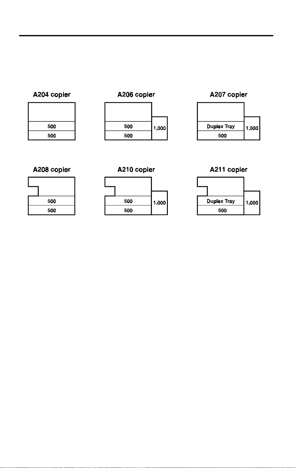
✽ Copy Paper Capacity:
Paper Tray By-pass Feed LCT
A204 copier About 500 sheets x 2 About 40 sheets —
A206 copier About 500 sheets x 2 About 40 sheets About 1,000 sheet s
A207 copier About 500 sheets x 1 About 40 sheets About 1,000 sheet s
A208 copier About 500 sheets x 2 About 40 sheets —
A210 copier About 500 sheets x 2 About 40 sheets About 1,000 sheet s
A211 copier About 500 sheets x 1 About 40 sheets About 1,000 sheet s
NOTE:
Paper tray - 500 sheets or less than 53 mm stack height
By-pass feed - 40 sheets or less than 4 mm stack height
LCT - 1,000 sheets or less than 120 mm stack height
Duplex Tray Capacity
[A207/A211]:
50 sheets (30 sheets for A3/11"x17"
81 ~ 105g/m
2
, 21.5 ~ 27.9 lb paper)
Toner Replenishment: Cartridge exchange (415 g/cartridge)
•
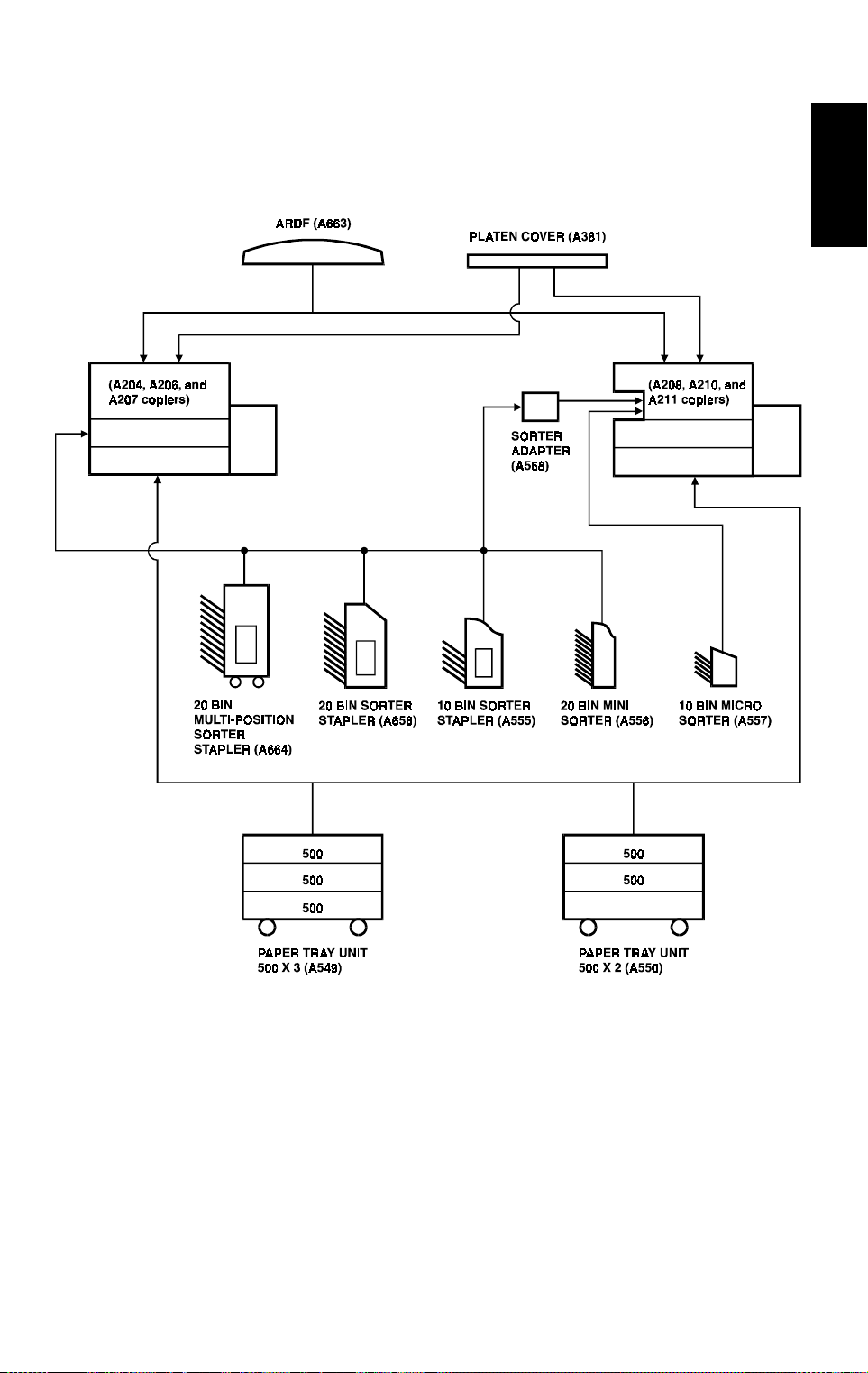
✽ Optional Equipment:
Platen cover
•
Document feeder
•
Paper tray unit with two paper trays
•
Paper tray unit with three paper trays
•
10 bin micro sorter (for A208, A210, and A211
copiers)
•
20 bin mini sorter
•
10 bin sorter stapler
•
20 bin sorter stapler
•
20 bin multi-position sorter stapler
•
Sorter adapter (required when installing 20 bin
mini sorter, 10 bin sorter stapler, 20 bin sorter
stapler, or 20 bin multi-position sorter stapler for
A208, A210, and A211 copiers)
•
Key counter
•
Tray heater
4
Page 8

31 March 1997 SPECIFICATIONS
•
Optical anti-condensation heater
•
Original length sensor for 11" x 15" size paper
(only for LT/DLT version)
•
ADS sensor for particular types of red original
•
Specifications are subject to change without notice.
Copier
5
Page 9
MACHINE CONFIGURATION 31 March 1997
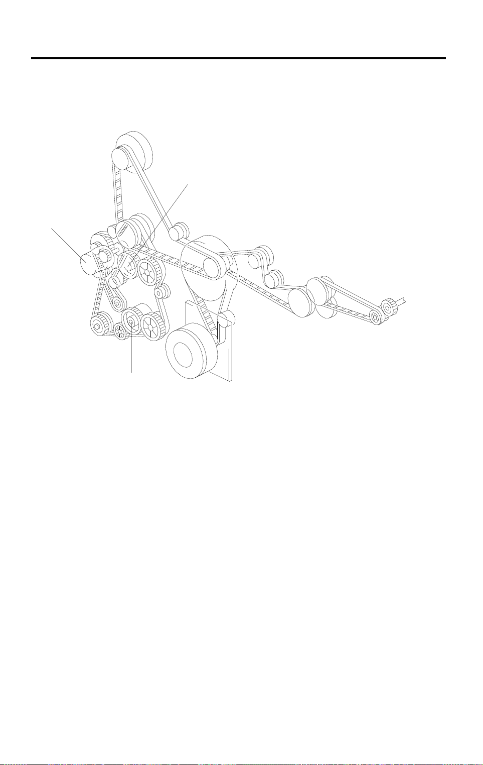
2. MACHINE CONFIGURATION
2.1 COPIER
A204V500.wmf
6
Page 10
31 March 1997 MACHINE CONFIGURATION
2.2 OPTIONAL EQUIPMENT
Copier
A204V501.wmf
7
Page 11

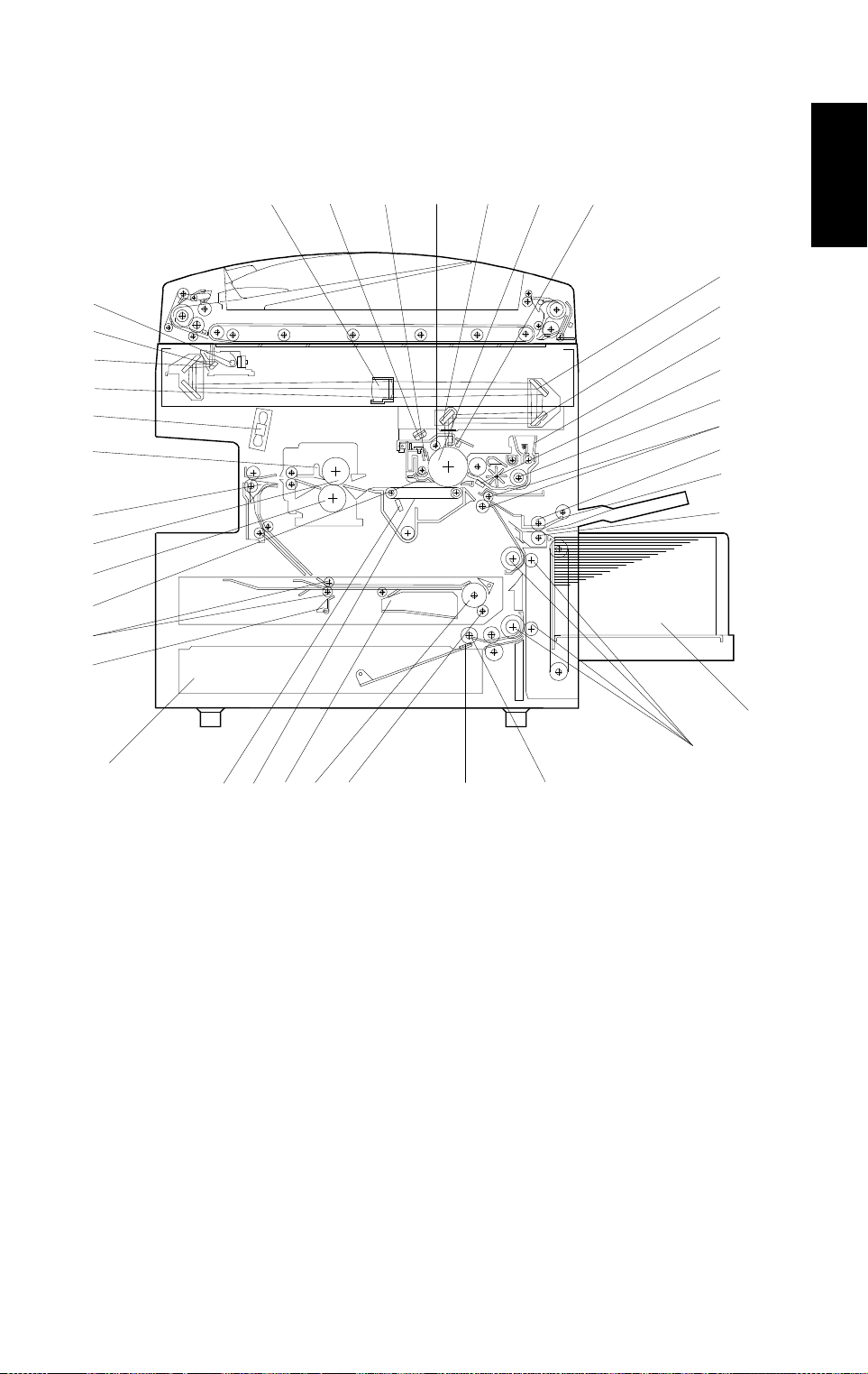
MECHANICAL COMPONENT LAYOUT 31 March 1997
3. MECHANICAL COMPONENT LAYOUT
– A207 copier –
56 91011
4
3
2
1
38
37
36
35
34
33
32
31
87
12
13
14
15
16
17
18
19
20
30
22
29
28 27 26 25 24
23
A204V502.wmf
The fusing unit has been changed. (See Detailed Descriptions for more
information.)
NOTE:
1) The A204 copier is the same as the A207 copier except that the
A204 does not have a duplex tray or an LCT.
2) The A206 copier is the same as the A207 copier except that the
A206 does not have a duplex tray.
21
8
Page 12
31 March 1997 MECHANICAL COMPONENT LAYOUT
– A211 copier –
4
3
2
1
38
37
36
35
34
33
32
31
56 91011
87
Copier
12
13
14
15
16
17
18
19
20
21
22
30
28 27 26 25
29
24
23
A204V503.wmf
The paper tray unit has been changed from the corner separation system to
the FRR feed system.
NOTE:
1) The A208 copier is the same as the A211 copier except that the
A208 does not have a duplex tray or an LCT.
2) The A210 copier is the same as the A211 copier except that the
A210 does not have a duplex tray.
9
Page 13

MECHANICAL COMPONENT LAYOUT 31 March 1997
1. 3rd Mirror
2. 2nd Mirror
3. 1st Mirror
4. Exposure Lamp
5. Lens
6. Quenching Lamp
7. Drum Cleaning Blade
8. Drum Charge Roller
9. 6th Mirror
10. OPC Drum
11. Erase Lamp
12. 4th Mirror
13. 5th Mirror
20. Separation Roller
21. Large Capacity Tray
22. Vertical Transport Rollers
23. Paper Feed Roller
24. Friction Pad
25. Duplex Friction Roller
26. Duplex Feed Roller
27. Jogger Fence
28. Transfer Belt
29. Transfer Belt Cleaning Blade
30. Lower Paper Tray
31. End Fence
32. Entrance Rollers
14. Toner Supply Unit
15. Pre-transfer Lamp
16. Development Unit
17. Registration Rollers
18. Feed Roller
19. Pick-up Roller
33. Pick-off Pawls
34. Pressure Roller
35. Hot Roller
36. Junction Gate
37. Hot Roller Strippers
38. Exhaust Fan
10
Page 14

31 March 1997 ELECTRICAL COMPONENT DESCRIPTIONS
4. ELECTRICAL COMPONENT DESCRIPTIONS
Refer to the electrical component layout and the point to point diagram on the
waterproof paper in the pocket for symbols and index numbers.
✽ : New or modified components
Symbol Name Function Index No.
Printed Circuit Boards
PCB1
PCB2
PCB3 DC Power Supply Provides dc power. 10
PCB4 Main Motor Co nt rol Controls the rotat ion of the main moto r. 94
PCB5
PCB6 T High Voltage Supply Supplies high voltage to the transfer belt. 52
PCB7
PCB8
PCB9
PCB10
PCB11
Main Control Controls all copier functions both directly or
through other control boards.
AC Drive Provides ac power to the exposure lamp
and fusing lamps.
CB High Voltage Supply Supplies high vo ltage to the drum charg e
roller and development roller.
Operation Pan e l Controls the LED matri x, and monitors th e
key matrix.
Noise Filter (220 ~ 240
V machines only)
Duplex Control
(Duplex mac h in es only)
Liquid Crystal Display
(A207 machines only)
LCT Interface
(LCT machines only)
Removes elect rical noise.
Controls the oper ation of the duplex tray.
Controls the gui dance dis play and displays
guidance for machine opera tion.
Interfaces the LCT control signal between
the main board and the LCT.
13
11
1
3
8
60
6
100
Copier
Motors
M1 Main Drives the ma i n uni t com ponents. 85
M2
M3
✽
M4
✽
M5
M6 Optics Cool i ng Fan 1 Removes h eat from the optics unit. 92
M7
✽
M8
Toner Bottle Drive Rotates the toner bottle to supply toner to
the toner supply u ni t .
Upper Tray Lift
(Non-duplex machines
only)
Lower Tray Lift Raises the bottom pl ate in the lower paper
LCT Lift
(LCT machines only)
Optics Cooling Fan 2 Removes h eat from the optics unit .
Exhaust Fan 1 Removes the heat from around the fusing
Raises the bottom pl ate in the uppe r paper
tray.
A204/206/208/ 210: M3 and M4 are
✽
combined into one unit
tray.
Lifts up and lower s t he LC T bottom plat e.
A208/210/211 now have two fans.
✽
unit.
11
76
95
83
97
93
87
Page 15

ELECTRICAL COMPONENT DESCRIPTIONS 31 March 1997
Symbol Name Function Index No.
M9
Exhaust Fan 2
(A204/A206/A207
Removes the heat fr om ar ound the fusing
unit.
88
machines only)
M10
Scanner Drive Drives the 1st and 2nd scanners (dc
stepper motor ).
90
M11 3rd Scanner Drive Drives the 3rd scanner (dc stepper motor). 75
M12 Lens Vertical Drive Shifts the lens vertical position. 84
M13 Lens Horizont al D r i ve Shifts th e l ens horizontal p osi t i on. 74
M14
M15
M16
M17
✽
Duplex Feed
(Duplex mac h in es only)
End Fence Jogge r
(Duplex mac h in es only)
Side Fence Jogger
(Duplex mac h in es only)
DC Board Cooling Fan
Motor (A204/A206/A207
Drives the feed roller and moves the
bottom plate up and down.
Drives the end f ence jogger to squar e t he
paper stack.
Drives the side f ence jogger to squar e the
paper stack.
55
58
57
Removes heat from t he dc power supply
board. 86
N. American mo del s)
Sensors
S1
S2
S3
S4
S5
✽
S6
S7
S8
✽
By-pass Feed Paper
Width
Informs the CPU what width paper is in the
by-pass feed ta bl e.
By-pass Feed Pa per End Informs the CPU that ther e i s no paper in
the by-pass tray.
Upper Tray Paper End
(Non-duplex machines
Informs the CPU wh en the upper paper
tray runs out of pap er. 48
only)
Upper Relay Detects the leadi ng edge of paper f ro m the
upper tray to dete rm i ne the stop timi ng of
the upper paper fee d clutch, and detects
misfeeds.
Upper Tray Upper Limit
(Non-duplex machines
only)
Detects the hei ght of the paper stack i n the
upper paper tray t o stop the upper tray lif t
motor.
A208/210/211 have the compone nt s
✽
needed for an FRR m echanism.
Lower Tray Paper End Informs the CPU when the l ow er paper tray
runs out of paper.
Lower Relay Detects the le ading edge of pape r from the
lower paper tray to determine the stop
timing of the low er paper feed clutch, and
detects misfeeds.
Lower Tray Upper Limit Detects the height of the paper stack in t he
lower paper tray to stop the lower tr ay l i f t
motor.
A208/210/211 have the compone nt s
✽
needed for an FRR m echanism.
26
30
105
28
49
104
29
12
Page 16

31 March 1997 ELECTRICAL COMPONENT DESCRIPTIONS
Symbol Name Function Index No.
S9
S10
S11
S12
S13
S14
S15
S16
S17
S18
S19
S20 Fusing Exit Detects mis fe eds. 42
S21
S22
S23
S24
S25
S26
S27
S28
LCT Lower Limit
(LCT machines only)
LCT Paper End
(LCT machines only)
LCT Upper Limit
(LCT machines only)
Registrati on Detects the leading edge of the copy pape r
Image Densi ty (I D) Detects the density of various patterns on
Toner Densi t y (TD) Detects the toner concentrat i on i nside the
Lens Horizont al H P Informs the CPU tha t the l ens is at the
Lens Vertical HP Informs the CPU that the lens is at the
Scanner HP Informs the CPU when the 1st and 2nd
3rd Scanner HP Informs the CPU when the 3rd scanner is
Original Length-2 Detects the lengt h of the original . Th i s i s
Platen Cover Informs the CPU whether the pl at en cover
Toner End Instructs the CPU to add toner to the toner
Auto Response Returns the operation panel display and
Transfer Belt Co nt act HP Informs the CPU of the current position of
Auto Image Density
(ADS Sensor)
Original Width Detects the width of the original. This is
Original Length-1 Detects the lengt h of the original . Th i s i s
Duplex Paper End
(Duplex mac h in es only)
Sends a signal to th e C P U to stop lowering
the LCT bottom p late.
Informs the CPU wh en the LCT runs out of
paper.
Sends a signal to th e C P U to stop lifting
the LCT bottom p late.
to determine the stop timing of the paper
feed clutch, and d et ect s misfeeds.
the drum durin g pr ocess control.
development unit.
horizontal ho me position.
full-size position.
scanners are at the h om e position.
at the home posit i on.
one of the APS (Auto Paper Select)
sensors.
is up or down (related to APS/ARE
functions). ARE: Auto R educe and Enlarge
supply unit, and detects toner end
conditions.
exits from the energy saver mode.
both the transfer belt unit and th e dr um
charge roller uni t .
Detects the background density of each
original in ADS mo de.
one of the APS (Auto Paper Select)
sensors.
one of the APS (Auto Paper Select)
sensors.
Detects paper i n t he duplex tray.
98
99
25
27
47
50
36
19
14
23
20
15
51
40
22
12
41
18
53
Copier
13
Page 17

ELECTRICAL COMPONENT DESCRIPTIONS 31 March 1997
Symbol Name Function Index No.
S29
Duplex Turn
(Duplex mac h in es only)
Detects the trailing edge of the copy paper
to determine the jo ggi ng timing, an d
54
detects misfeeds.
S30
S31
S32
S33
Duplex Entrance
(Duplex mac h in es only)
Side Fence Jogger HP
(Duplex mac h in es only)
End Fence Jogge r HP
(Duplex mac h in es only)
Original Length
(Option for N. American
Detect s m i sfeeds.
Detects the hom e position of the duplex
side fence jogger.
Detects the hom e position of the duplex
end fence jogger.
Detects orig inal l ength for 11" x 15" p aper.
59
56
61
21
models)
Switches
SW1
SW2
SW3
✽
By-pass Feed Table Detects whether the by-pass feed table is
open or closed.
Tray Down
(LCT machines only)
Upper Tray Paper Siz e
(Non-duplex machines
only)
Sends a signal to the CPU to lower the
LCT bottom plate.
Determines w hat si ze of paper is in th e
upper paper tray, and detects when th e
tray has been cl osed.
The upper tray swi t ch has been
✽
32
102
24
eliminated.
Lower Tray Pap er Siz e Determines what size of paper is in the
lower paper tray, and detects when the tray
SW4
✽
has been closed.
The lower tray switch has been
✽
33
eliminated.
SW5
Vertical Guide Set
(Non-LCT m achines
Detects whether the vertical gui de i s open
or not. 31
only)
SW6
SW7
LCT Cover-1
(LCT machines only)
LCT Cover-2
(LCT machines only)
Detects whether the LCT cover is ope n or
not.
Cuts the dc power l i ne of the LCT lift motor.
103
101
SW8 Main Supplies power to t he copier. 39
SW9
SW10
Front Cover Saf e t y Cuts the ac power line and detects whether
the front door is open or not.
Exit Cover Safety
(A211 machines only)
Cuts the ac power l i ne and detects whet her
the exit cover is open or not.
38
45
Magnetic Clutches
CL1
Toner Supply Turns the toner supply roller to supply
toner to the devel opment unit.
CL2 Dev elopment Drives t he develo pment roller. 68
14
69
Page 18

31 March 1997 ELECTRICAL COMPONENT DESCRIPTIONS
Symbol Name Function Index No.
Transfer Belt Co nt act Controls the touch and releas e m ovement
CL3
CL4 Registration Drives the registration rollers. 70
CL5
CL6 Relay Drives the relay rollers. 73
CL7
CL8 Lower Paper Feed Starts paper feed fr om the lower paper tr ay. 82
Solenoids
SOL1
SOL2
SOL3
SOL4
✽
SOL5
✽
SOL6
✽
SOL7
✽
By-pass Feed Starts paper feed from the by-pass feed
Upper Paper Feed
(Non-duplex machines
only)
LCT machines:
LCT/By-Pass Pick -u p
Solenoid
Non-LCT machi nes:
By-pass Pick-up
Solenoid
Junction Gate
(Duplex mac h in es only)
LCT Pick-up
(LCT machines only)
Upper Tray Pick-up
(Non-duplex machines
only)
Lower Tray Pick -up Controls the up/ down movement of th e
Upper Tray Separ at i on
(Non-duplex machines
only)
Lower Tray Separation Controls the up-down movement of the
of both the transfer bel t uni t and the drum
charge roller uni t .
table or LCT.
Starts paper feed from the upper paper
tray. 81
Picks paper up from t he by-pass feed
table. When paper is fed from the LC T, this
solenoid ass i st s SO L3.
Moves the junction gate to direc t copies to
the duplex tray or to the paper exit.
Picks up paper from t he LC T.
Controls the up/down movement of the
pick-up roller i n the upper paper tray.
A208/210/211 have the compone nt s
✽
needed for an FRR m echanism.
pick-up roller i n the lower paper tr ay.
A208/210/211 have the compone nt s
✽
needed for an FRR m echanism.
Controls the up- down move m ent of the
separation rol l er in the upper pap er tr ay
feed station.
A208/210/211 have the compone nt s
✽
needed for an FRR m echanism.
separation rol l er in the lower pa per tr ay
feed station.
A208/210/211 have the compone nt s
✽
needed for an FRR m echanism.
91
71
72
89
96
77
79
78
80
Copier
Lamps
L1
✽
Exposure Applies high intensity light to the original for
exposure.
Modified - see the "O pt i cs" section for
✽
details.
15
16
Page 19

ELECTRICAL COMPONENT DESCRIPTIONS 31 March 1997
Symbol Name Function Index No.
Main Fusing Provides heat to the central area of the hot
L2
✽
roller.
Modified - see the "Fusing" section for
✽
62
details.
Secondary Fu si ng Provides heat to both ends of the hot roller.
L3
✽
Modified - see the "Fusing" section for
✽
63
details.
Pre-transfer Red uces the charge re maining on the
L4
drum surface bef or e t ransfer. 4
Quenching Neutralizes any charge rem a in ing on the
L5
drum surface af te r cleaning.
5
Erase After exposure, this eliminates the charge
L6
on areas of the drum that will not be used
2
for the image.
Heaters
Drum Turns on when the main switch is off to
keep the temperature around the drum
H1
charge roller at a certain level. Also
35
prevents moisture from forming around the
drum.
H2
Optics Anti-c ondensation
(option)
Turns on when the main switch is off to
prevent moisture from forming on the
43
optics.
H3
Lower Tray (option) Turns on when the main switch is off to
keep paper dry i n th e l ow er paper tray.
34
Thermistors
TH1
Main Fusing Monitors the tem perature at the central
Secondary Fu si ng
TH2
✽
(A208/A210/A2 11
machines only)
TH3
TH4
Optics Monitors the temperature of the optics
Drum Charge Monitors the temperature of the drum
Thermofuses
TF1
Main Fusing Provides back-up overheat pro te ct i on i n
Secondary Fu si ng
TF2
✽
(A208/A210/A2 11
machines only)
area of the hot roll er.
Monitors the tem perature at the e nds of the
hot roller.
A204/206/207 have only one thermi st or.
✽
cavity.
charge roller .
the fusing unit.
Provides back- up overheat pro te ct i on i n
the fusing unit.
A204/206/207 have only one thermofuse.
✽
16
66
67
44
46
65
64
Page 20

31 March 1997 ELECTRICAL COMPONENT DESCRIPTIONS
Symbol Name Function Index No.
TF3
Counters
CO1
CO2
Others
CB1
TR1
CC1 This has been eli minated from all m odels.
Exposure Lamp Opens the exposure lamp circuit if the 1st
scanner overheats.
Total Keeps t rack of the total num ber of copies
made.
Key (option) Used for co nt rol of authorized use. The
copier will not operate until it is installed.
Circuit Breaker (220 ~
240 V machines onl y)
Transformer (220 ~ 240
V machines only)
Provides back-up high current protection
for electrical components.
Steps down the wall voltage to 100 Vac.
17
37
N/A
9
7
Copier
17
Page 21
PAPER FEED DRIVE LAYOUT 31 March 1997
5. PAPER FEED DRIVE LAYOUT
5.1 A204/A206/A207/A208/A210/A211
1
3
2
A204V504.wmf
Since A208, A210, and A211 have been changed to the FRR feed system, all
models carry the same type of drive layout.
1. Upper Paper Feed Clutch Gear (A207/A211 only)
2. Lower Paper Feed Clutch Gear
3. Relay Clutch Gear
18
Page 22

31 March 1997 PROCESS CONTROL
6. PROCESS CONTROL
6.1 HALFTONE MODE
This mode is newly added.
If the user selects the halftone mode function on the operation panel, the
machine reduces the size of the exposure lamp voltage, development bias,
and the drum charge voltage by the changes shown below.
•
Exposure Lamp Voltage: –1.0 V
•
Development Bias: +80 V
•
Drum Charge Voltage: +300 V
6.2 ADS CORRECTION
✽ Five possible corrections can be selected from, where the base copier has
only three.
Copier
ADS correction
ADS Density SP5-106
Setting Copy Density
0 Dar kest 816 x (AR – 0.85) + 60
✽
1 Darker 816 x (AR – 0.75)
2 Nor m al 816 x (AR – 0.85)
3 Lighter 816 x (AR – 0.95)
4 Lightest 816 x (AR – 0.85) – 60
✽
Where AR (ADS Ratio) = V
Development Bi as C orrection Voltage
ADS
(original)/V
ADS
(pattern)
19
Page 23

PROCESS CONTROL 31 March 1997
6.3 TONER SUPPLY CONTROL DURING COPYING
✽ The amount of toner supplied per unit of time (TS) has been changed from
the base copier.
Toner clutch on time is calculated by the following formula.
Toner CL on time [ms] =
S x
AT x
TSC
TS
⁄⁄
100
(Formula 1)
where: S = Copy paper size [cm
AT = Amount of toner developed on the latent image per unit area
= 0.7 [mg/cm
2
] (constant)
TSC = Toner supply coefficient [%]
✽ TS= Amount of toner supplied per unit of time
= 0.217 [mg/ms] (for A204, A206, and A207 copiers)
= 0.183 [mg/ms] (for A208, A210, and A211 copiers)
2
]
20
Page 24

31 March 1997 PROCESS CONTROL
6.4 VR PATTERN CORRECTION
✽ The values in the ID correction column of the table have been changed.
R
correction
V
ID Correction
–40 V –80 V
V
RP/VRG
100 (%)
x
±±
0 V
74 ~ 100 68 ~ 100 62 ~ 100
53 ~ 73 50 ~ 67 43 ~ 61 –40 V –40 V
41 ~ 52 37 ~ 49 26 ~ 42 –80 V –80 V
31 ~ 40 26 ~ 36 19 ~ 25 –120 V –120 V
0 ~ 30 0 ~ 25 0 ~ 18 –160 V –160 V
For example, taking the ID correction to be zero for now, if VRP/V
Drum Charge Roller
Correction Voltage
0 V
±
Development Bia s
Correction Volt age
0 V
±
RG
is 45%,
the drum charge and development bias corrections will both be –80 V.
R
V
correction also depends on the current VSP pattern ID correction that is
being used. If development bias has been increased by ID correction, the V
correction may be smaller in some cases to take this into account. This is
shown by both the table above and the following diagram.
–160 V
–120 V
ID correction
0 V
–40 V
–80 V
Copier
R
–80 V
–40 V
Correction Voltage
R
V
–0 V
10080604010 20 30 50 70 90
Drum residual
voltage largel
VRP/VRG (%)
Drum residual
voltage small
A204D505.wmf
Using the same example to illustrate this, but with an ID correction of –80 V,
the corrections will both be –40 V this time.
21
Page 25

PROCESS CONTROL 31 March 1997
6.5 TONER SUPPLY IN ABNORMAL SENSOR CONDITIONS
If any sensor errors occur under detect supply mode, toner supply mode is
changed automatically as shown below.
Error Abnorma l Cond ition
ID Sensor
Adjustment Error
Abnormal ID Sensor
SP
)
(V
Abnormal ID Sensor
SG
)
(V
TD Sensor
Adjustment Error
TD Sensor (V
T
)
Measurem ent Error
Drum Charge
Thermistor Error
Abnormal Drum
✽
Charge Thermistor
Output
When ID senso r output
cannot be adjusted to
4.0 ± 0.2 V
SP
> 2.5 V during
If V
SP
V
detect i on.
SG
If V
< 2.5 V during
SG
detection
V
When TD sensor
output cannot be
adjust ed to 2.5 ± 0.1 V
If VT > 4.0 V or VT <
0.3 V during V
T
detection.
Temperature det ected
by the drum cha rge
thermistor is below 0°C
or above 60°C
Temperature det ected
by the drum cha rge
thermistor is between
0°C and 14°C
Fallback Toner
Supply Mode
Display on
Operation Panel
Fixed Supply Mode None
Fixed Supply Mode None
Fixed Supply Mode
Fixed Supply Mode Manual ID level or
ADS indicator blinks
Fixed Supply Mode Manual ID level or
ADS indicator blinks
Fixed Supply Mode None
TD Sensor Supply
None
Mode
NOTE:
No indication is displayed under the "abnormal drum charge
thermistor output" condition, because the machine soon recovers
due to the heat inside the machine.
22
Page 26
31 March 1997 PROCESS CONTROL
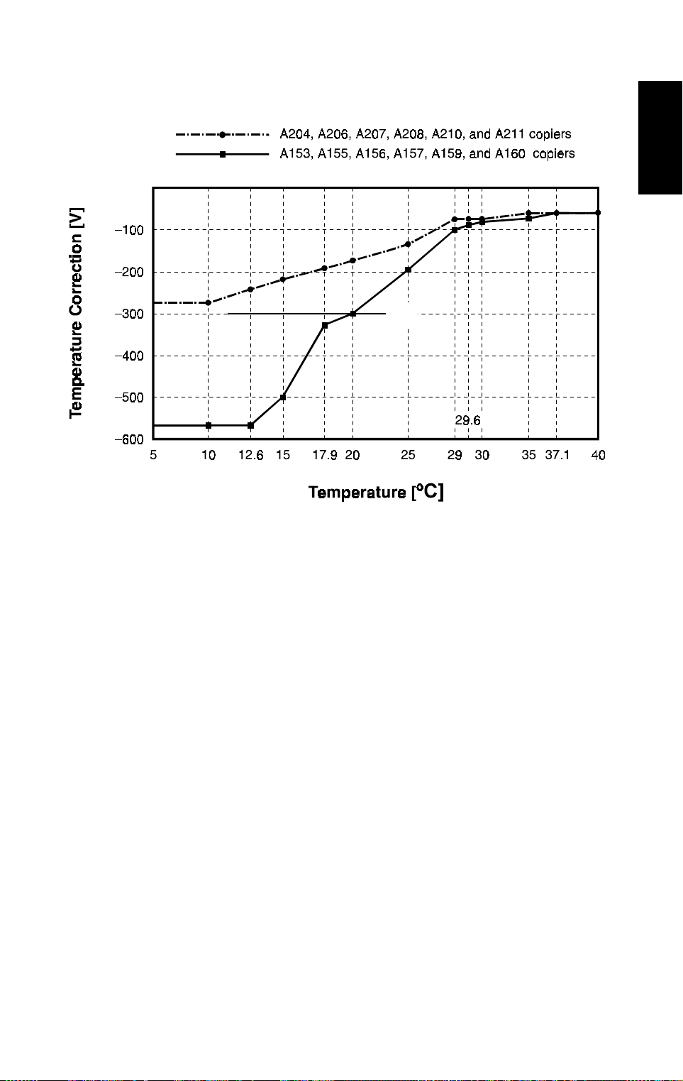
6.6 TEMPERATURE CORRECTION
[A]
Copier
A204D506.wmf
✽ The temperature correction has changed as explained below. Also, the
machine no longer does the drum rotation time correction.
The temperature correction difference between the A204, A206, and A207
copiers and the A208, A210, and A211 copiers is a result of the difference in
copy processing speed (240 mm/s for the A204, A206, and A207 copiers,
compared with 200 mm/s for the A208, A210, and A211 copiers).
The new drum charge roller needs only about half the correction voltage
used for the base copier. Also, the level of correction needed for the lowest
temperature point (5°C) is about the same as the normal room temperature
point for the base copier [A].
In the base machine, rotation time correction was only needed for low
temperatures where the temperature correction was large. In the new
machines, the temperature correction is never greater than –300 V, so the
rotation time correction has been eliminated.
23
Page 27

PROCESS CONTROL 31 March 1997
The temperature corrections are as shown below.
•
Temperature Correction (Copying) - Base drum charge voltage = –1,500 V
•
Temperature Correction (VSP Pattern) - Base drum charge = –1,370 V
– A204, A206, and A207 –
Drum Charge Roller
Temperature (°C)
35.0 ≤ T
28.0 ≤ T < 35.0
10.0 ≤ T < 28.0
T < 10.0 –130.0 –295.0
– A208, A210, and A211 –
Drum Charge Roller
Temperature (°C)
35.0 ≤ T
29.0 ≤ T < 35.0
10.0 ≤ T < 29.0
T < 10.0 –120.0 –260.0
Temperature Correcti on
V
Pattern Copying
SP
+53 –57.0
–83.5 + 3.9T –211.0 + 4.4T
–217.6 + 8.7T –410.0 + 11.5T
Temperature Correcti on
V
Pattern Copying
SP
+47 –61.0
–51.0 + 2.8T –173.0 + 3.2T
–199.1 + 7.9T –3 55.5 + 9.5T
24
Page 28

31 March 1997 PROCESS CONTROL
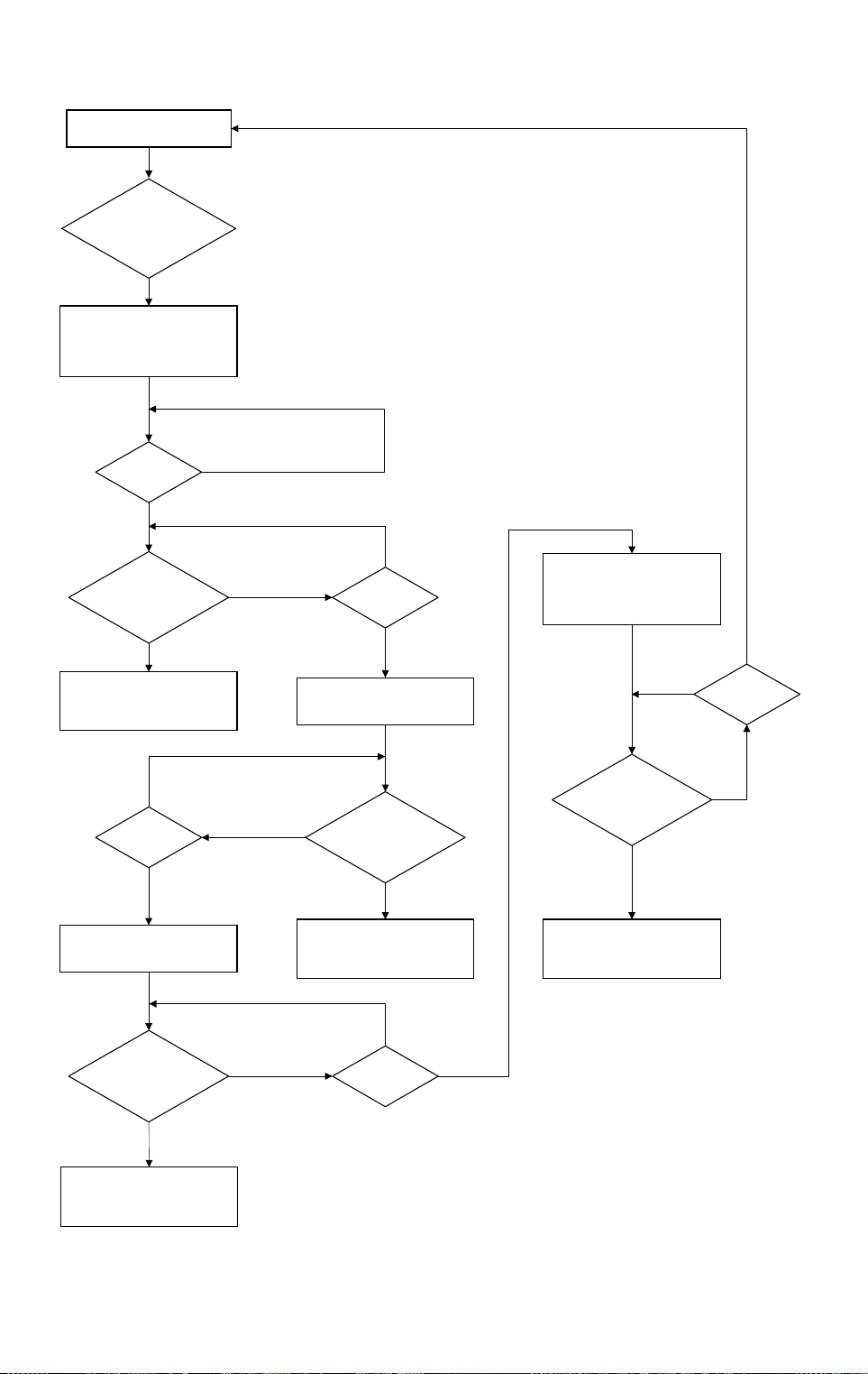
6.7 TONER END RECOVERY
If the front cover switch or the main switch is turned off and on during a toner
near-end/end condition, the machine will perform the toner end recovery
procedure as shown on the flow chart on the next page.
For the base copier, the toner end sensor checked for toner for a total of 10
seconds. The check stops when the toner supply clutch stops transporting
toner.
For the A204 series, the toner sensor checks for toner for a total of 14
seconds, stopping 2 seconds after the toner supply clutch stops. When the
toner supply clutch stops, any toner present is likely to drop into the
development unit, which will be detected during the final 2 seconds of
detection time. This will decrease the chances of a mis-detection when a new
toner bottle has been installed by the customer.
Copier
A153/A155/A156/
A157/A159/A160
A204/A206/A207/
A208/A210/A211
Toner Supply
Clutch
Toner End
Sensor
Toner Supply
Clutch
Toner End
Sensor
ON
OFF
ON
OFF
ON
OFF
ON
OFF
10
2
2 255
2
A204D516.wmf
25
Page 29
PROCESS CONTROL 31 March 1997
Toner End Condition
Yes
Front
Cover Switch or Main
Switch Turned OFF/
ON?
Yes
Drum Drive, Development
Clutch, Toner Supply Clutch,
Toner Bottle Drive Motor
Turn On. t = 0s.
t ≥ 2s
Toner End
Detection. Is Toner
Present?
Components Turn Off. Toner
End/Near End Condition is
Canceled.
t ≥ 7s
Toner Supply Clutch, Toner
Bottle Drive Turn On.
No
Yes
No
Yes
No
Yes
No
t ≥ 5s
Yes
Toner Supply Clutch, Toner
Bottle Drive Turn Off.
Toner End
Detection. Is Toner
No
Components Turn Off. Toner
Present?
Yes
End/Near End Condition is
Canceled.
Drum Drive, Development
Clutch, Toner Supply Clutch,
Toner Bottle Drive Motor
Turn Off.
No
Toner End
Detection. Is Toner
Present?
Yes
Components Turn Off. Toner
End/Near End Condition is
Canceled.
No
Yes
t ≥ 14s
Toner End
Detection. Is Toner
Present?
Yes
Components Turn Off. Toner
End/Near End Condition is
Canceled.
t ≥ 12s
No
YesNo
A204D515.wmf
26
Page 30
31 March 1997 PROCESS CONTROL
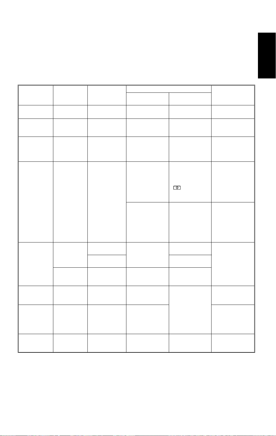
6.8 SUMMARY
NOTE:
Only items marked with ✽ are different or reviewed from A153, A155,
A156, A157, A159, and A160 copiers.
A summary of process control and correction timing is shown below.
Correction
Manual ID
correction
Reproduction
ratio
correction
✽
Halftone mode
ADS
correction
ID
correction
and
Toner density
control
R
V
correction
L
V
correction
✽
Temperature
correction
Electrical
Component
Operation
panel
Operation
panel
Operation
panel
ADS sensor
ID sensor
TD sensor VT
ID sensor V
ID sensor V
Drum charge
roller
thermistor
Sensor Output
V
ADS
V
ADS
T: (temperature) —
Used
——
——
——
Forced Correction
(pattern)
(original)
SG
V
SP
V
RP
, V
LP
, V
New exposure
lamp, ADS sensor,
after SP4- 001
(Exposure lamp
voltage
adjustment) or
optics cleaning
New drum, ID
sensor or ID
sensor cleaning
When the
developer is
changed
New drum or ID
sensor replacement
RG
New drum,
exposure lamp or
LG
after SP4- 001
(Exposure lamp
voltage adj ustment)
Correction Timing
Every copy in
manual ID mode
Every copy in
reduce/enlarge
mode
Every copy in
halftone mode
ADS Mode:
•
Once per original
—
(ARDF mode), or
once when the
! key is
pressed (Platen
mode)
Every 1,000 copies
At the start of
each copy job
About every 10
copies
Every copy
After every 1,000
copies
Every copy Drum charge roller
Automatic
Correction
Corrected Value
Lamp voltage
•
Dev. bias
•
Development bias
Lamp voltage
•
Dev. bias
•
Drum charge
•
roller voltage
Development bias
ADS
V
•
(pattern)
is stored
Dev. bias
•
Toner supply
•
clutch ON
time
Drum charge
•
roller voltage
Dev. bias
•
Lamp voltage
voltage
Copier
27
Page 31

PROCESS CONTROL 31 March 1997
L
L
V
correction
V
correction
+
Halftone Mode
correction
Manual ID
✽
+
Vexp +
0
0
L
V
correction
Vexp
L
V
correction
Vexp +
detection routi ne.
L
correction
✽
Temperature
+
R
V
Halftone Mode + C
correction
✽
+
(–1500) +
R
V
correction
+
V
R
+ B Vexp +
correction
+
R
V
correction
+
ratio
ratio
rati o
correction
Reproduction
are different from A153, A155, A156, A157, A159, and A160 copiers.
✽
(–240) + ADS correction +
correction
Reproduction
+
Halftone Mode + B
✽
+
correction
Manual ID
(–240) +
correction
Reproduction
+
bias
dev.
Lightest ID level
(–240) +
+ CP
correction
✽
Temperature
+
correction
✽
Temperature
–1370) +
✽
(
0
Halfotone Mode + B
✽
+
(–300) + BP + ID correction
+ C
R
V
correction
(–1500) +
+ VBL (ID) Vexp +
+ VBL (ID)
R
V
correction
BL +
+ VBL (ID) 0 0
R
V
correction
BL + (–25) +
00
R
V
correction
(–200) +
ADS mode
Mode Development Bias [V] Drum Charge Voltage [V] Exposure Lamp Voltage [V]
Only items marked with
The following table shows how process control af fe cts development bi as, drum charge, and exposure lamp voltages for various machi ne
Development bias, drum charge voltage, and exposure lamp voltage
NOTE:
operations.
ID Level
1 ~ 6
Manual
Copying
ID
ID Level
mode
7
Detection
Forced VL
VL Detection
B = Development bias adjustm ent factor, selected with SP2-201- 001.
VR Pattern Detection
VSP Pattern Dete c ti o n
VL
Pattern
Non Image A r ea
Detection
Auto ADS Gain Adjustment
NOTE:
BP = Correction to the development bias used for making for VSP patterns, selected with SP2-203.
(ID) = ID compensation factor based on the current ID correction used for ma king VSP patterns.
BL
BL = The value of t he development bias that was reached during the m ost recently perfo rm ed forced V
V
C = Correction to the drum charge voltage, selected with SP2-001.
CP = Correction to the drum charge voltage for maknig VSP patterns, selected with SP2-003.
Vexp = Exposure lam p voltage, select ed wi t h SP4- 001.
28
Page 32

31 March 1997 DRUM
7. DRUM
7.1 DRUM CHARGE ROLLER CLEANING
✽ The cleaning interval and the cleaning time have been changed.
The drum charge roller cleaning routine is executed at the following intervals:
1) For 2 seconds at the end of every job
2) ✽ For 5 seconds after the copy job interval set by SP2-901.
SP2-901 setting: 0: Every 1,000 copies (5 seconds)
1: Every 500 copies (5 seconds) [✽ new default]
2: Every 200 copies (5 seconds)
3: Every 100 copies (5 seconds)
The effect of the change in the default setting is to do the cleaning more
frequently.
Copier
29
Page 33

OPTICS 31 March 1997
8. OPTICS
8.1 OVERVIEW
8.1.1 Halogen Lamp
✽ The specifications of the halogen lamp have been changed as follows.
Note that the A204/A206/A207 models are faster, so they need more light
during exposure.
115 V Machines 230 V Machines
A204/A206/A207 97 V 310 W 85 V 310 W
A208/A210/A211
The halogen la mps installed i n t he A208/A210/A211 ar e t he same as for the
✽
A153/A155/A156 copiers
8.1.2 Toner Shield Glass
✽ The shield glass by the green filter above the drum has been removed (it is
no longer needed).
97 V 200 W
✽
85 V 280 W
✽
8.1.3 Optics Cooling Fans
✽ The optics cooling fan specifications have changed. Both models now have
two fans; this is because the cpm for the A207/A210/A211 models has
been increased from the previous models (27 → 32). Also the rotating
speed has been changed as follows:
A204/A206/A207 A207/A21 0 / A211
Rotating speed 3,450 rpm
Rotating te m per at ure
Number of fans 2 2
The rotating speed of 3,200 rpm is as same as for the A153/A155/A156 copiers.
✽
45°C45
3,200 rpm
✽
C
°
8.2 SCANNER DRIVE
✽ The scanner drive speeds have changed as follows.
The first scanner drive speed in full size mode is:
240 (mm/s) for A204/A206/A207 copiers
200 (mm/s) for A208/A210/A211 copiers
The first scanner drive speed for a selected reproduction ratio is:
240/M (mm/s) for A204/A206/A207 copiers
200/M (mm/s) for A208/A210/A211 copiers
NOTE:
M = Selected reproduction ratio (0.5 ~ 2.0)
30
Page 34

31 March 1997 OPTICS
8.3 ADS SAMPLING DURING COPYING
Copier
A204D511.wmf
✽ The position of the sampling area has been changed (in the base copier, it
was 60 mm from the edge and 38 mm wide).
31
Page 35

PAPER FEED AND REGISTRATION 31 March 1997
9. PAPER FEED AND REGISTRATION
9.1 OVERVIEW
- A204/206/207/208/210/211 -
[B]
[C]
[A]
A204D512.wmf
✽ All of the above-mentioned models use the FRR system.
This model has three paper feed stations: the large capacity tray feed station
[A] (LCT machines only), the upper paper tray feed station (non-duplex
machines only), and the lower paper tray feed station [B].
The LCT holds 1,000 sheets of paper. The upper and lower paper trays are
drawer trays that hold 500 sheets of paper.
Paper can also be fed using the by-pass feed table [C], which uses the feed
mechanism of the LCT feed station. The by-pass feed table can hold 40
sheets of paper. All feed stations use the FRR feed system.
The top sheet of paper separates from the stack and is fed to the relay
rollers, then to the registration rollers.
There are two relay sensors, one located just under each set of relay rollers.
These sensors are used for paper jam detection.
32
Page 36

31 March 1997 IMAGE FUSING (A204 /A2 06/ A207 COPIERS)
10. IMAGE FUSING (A204/A206/A207 COPIERS)
10.1 OVERVIEW
13
1
Copier
11
12
10 9 8
2
3
4
5
6
7
A204D513.wmf
1. Thermofuse
✽
2. Oil Supply Roller
✽
3. Oil Supply Roller Cleaning
✽
7. Pressure Roller
8. Cleaning Roller
9. Secondary Fusing Lamp
✽
Brush
10. Fusing Exit Rollers
4. Main Fusing Lamp
✽
11. Fusing Exit Sensor
5. Pressure Springs
12. Hot Roller Strippers (7 pcs)
6. Hot Roller
✽
✽
13. Thermistor
The fusing unit for the A204/206/207 has several new features, which are
described in the following pages.
NOTE:
The fusing unit for the A208/210/211 is the same as the fusing unit
for the A153/155/156 except for the drawer connector (the shape for
changed), and uses the same parts (hot roller, etc).
33
Page 37

IMAGE FUSING (A204/A206/A207 COPIERS) 31 March 1997
10.2 OIL SUPPLY MECHANISM
[B]
[C]
[A]
[D]
A204D517.wmf
The oil supply is necessary for a 40 cpm copier. An oil supply roller [A] is
installed above the hot roller [B]. It is always in contact with the hot roller, and
applies a light coat of silicone oil as the roller rotates.
The oil supply roller is made of paper soaked with silicone oil wrapped
around the shaft, and covered with PTFE (polytetra fluoroethylene) tube. As
the temperature of the hot roller rises, the PTFE tube contracts and squeezes
the oil-soaked paper, and the oil comes out through the coating.
The oil supply roller cleaning brush [C] under the oil supply roller removes the
toner and paper dust accumulated on the oil supply roller.
The oil supply roller shaft is installed on a one-way bushing [D], to prevent
collected toner from returning to the hot roller surface by the customer
operating the fusing knob manually in the reverse direction.
34
Page 38

31 March 1997 IMAGE FUSING (A204 /A2 06/ A207 COPIERS)
10.3 FUSING LAMP CONTROL
Copier
A204D514.wmf
There are two fusing lamps in the hot roller: the main fusing lamp (800 W) [A]
and the secondary fusing lamp (350 W) [B].
The main fusing lamp has a much higher wattage that the one in the base
copier, because it is the only lamp that is used during copying to control the
operating temperature of the fusing unit (185°C).
The secondary fusing lamp is only used in the following conditions to help
achieve a faster warm-up time.
•
When the main switch is turned on
•
When exiting from the energy saver mode
The new hot roller’s metal core is thicker than the base copier’s hot roller’s.
The new roller holds heat much better, to allow multicopying at the higher
cpm of this model without the hot roller temperature dropping too far.
However, it takes a lot longer to warm up after switching on (see the
Warm-up Time in the Specifications section).
The temperature is only monitored at the center; there is only one fusing
thermistor. There is also only one thermofuse.
35
Page 39

IMAGE FUSING (A204/A206/A207 COPIERS) 31 March 1997
When the main switch turns on, the CPU checks the mains frequency for 500
ms; this is done in case phase control mode is selected later. Then the CPU
turns on the main fusing lamp. After 3 more seconds, the secondary fusing
lamp is turned on. This delay reduces the surge current after the main switch
is turned on.
Both lamps are turned on to raise the temperature of the hot roller’s surface.
When the thermistor detects the operating temperature (185°C), the copier
turns off the secondary fusing lamp, and starts fusing idling for 100 seconds
to warm up the hot roller completely and evenly (the roller has a thicker metal
core), and to distribute the oil. During fusing idling, the temperature is kept at
185°C.
When fusing idling is finished, the copier enters the ready condition. The CPU
keeps the temperature at 185°C by turning off and on the main fusing lamp.
The lamp is turned off at 190°C, and on at 180°C.
If the fusing lamp turns on while the exposure lamp is on, the power supplied
to the exposure lamp may fluctuate, possibly degrading the copy quality. To
prevent this, in this machine, the fusing lamp can either stay off or change
from on to off while the exposure lamp is on.
There are two types of fusing unit control: on/off control, and phase control.
The mode can be selected with SP1-104.
36
Page 40

31 March 1997 INSTALLATION
11. INSTALLATION
11.1 COPIER ACCESSORY CHECK
Check the accessories against the following list:
Description Q’ty
1. Paper Size Decal.............................................................. 1
2. Symbol Explanation Decal
(except for the A207 copier) ............................................. 1
3. Optional Zoom Function Decal......................................... 1
4. Optional Margin Adjustment Function Decal.................... 1
5. Combine Originals Explanation Decal
(except for the A207 copier) ............................................. 1
6. Receiving Tray.................................................................. 1
Copier
7. Operating Instructions (except for -27 machines) ............ 1
8. User Survey Card (-17 machines only) ............................ 1
9. New Equipment Condition Report................................. ... 1
10. Cushion ............................................................................ 1
37
Page 41

INSTALLATION 31 March 1997
11.2 COPIER INSTALLATION PROCEDURE
CAUTION
Rating Voltage for Peri pherals
Make sure to plug the cables into the correct sockets.
38
A204I516.wmf
Page 42

31 March 1997 INSTALLATION
–A204/A206/A207 copiers–
[C]
[A]
[F]
–A206/A207/A210/A211 copiers–
Copier
[B]
–A208/A210/A211 copiers–
[A]
[B]
NOTE:
1) Never lift the machine by holding the LCT, or the LCT will break.
2) Keep the shipping retainers after installing the machine. They will
be reused if the machine is moved to another location in the future.
[E]
[D]
A204I500.wmf
[C]
A204I501.wmf
[F]
[E]
A204I502.wmf
3) Proper reinstallation of the shipping retainers is required in order
to avoid any transport damage. It is most important to put back the
scanner lock pin when transporting this copier. If not, skewed
image may result.
1. Remove the scanner lock pin [A] and red tag [B] as shown.
2. Remove the strips of tape and the sheet of paper [C]. Also, for
A206/207/A210/A211 copiers, remove the strip of tape on the LCT [D].
3. Pull out the paper tray [E], and remove the strips of tape and the bottom
plate stopper [F]. Then install the paper tray in the copier (1 tray for
duplex machines and 2 trays for non-duplex machines).
39
Page 43

INSTALLATION 31 March 1997
–A207 copier–
[H]
[F]
[I]
[D]
[G]
[C]
[F]
[B]
[B]
[E]
A204I503.wmf
–A211 copier–
[F]
[A]
[C]
[H]
[B]
[I]
[D]
[B]
A204I504.wmf
4.
A207/A211 copiers only:
[G]
[F]
1) Pull out the duplex tray [A] and remove the strips of tape [B].
2) Remove the guide roller stopper [C] and a sheet of paper [D].
3) Open the upper duplex guide plate [E] and remove the strips of tape
[F].
4) Open the lower duplex guide plate [G], and remove the styrofoam
support [H] and the sheet of paper [I].
5) Install the duplex tray in the copier.
[A]
[E]
40
Page 44

31 March 1997 INSTALLATION
–A204/A206/A207 copiers–
[C]
[B]
A204I505.wmf
–A208/A210/A211 copiers–
[B]
[A]
[G]
[A]
[F]
[D]
Copier
[E]
A204I506.wmf
[B]
A204I507.wmf
5. Open the front cover and swing out the toner bottle holder [A].
6. Remove the strips of tape [B].
7. Remove the switch actuator lock bracket [C] as shown.
8. Turn the "A1" lever [D] counterclockwise to lower the transfer belt unit.
Then remove the cushion sheet [E].
9. Remove the blade release wedge [F] together with the pick off pawl
release mylar [G].
10. Return the "A1" lever to the set position.
41
Page 45

INSTALLATION 31 March 1997
[D]
[C]
[B]
[H]
[A]
A204I508.wmf
[F]
[G]
A204I509.wmf
11. Remove the knob screw [A].
12.
Swing out the bottle holder [B] and ➁ pull down the lock lever [C].
➀
Then slide out the bottle holder assembly [D] and ➃ swing out the
➂
bottle holder assembly [D].
13. Remove the knob screw [E] and disconnect the white connector [F].
14. Pull down the development unit lock lever [G] from under the plate and
pull out the development unit [H]. Then place it on a clean sheet of paper.
[E]
42
Page 46

31 March 1997 INSTALLATION
[A]
[B]
Copier
[F]
[E]
A204I510.wmf
[C]
[D]
A204I511.wmf
15. Disconnect the connector [A] and separate the toner supply unit [B] from
the development unit (2 screws).
16. Pour about half a pack of developer [C] into the development unit. Then
rotate the outer gear [D] as shown to distribute the developer evenly.
Then pour in all the remaining developer and rotate the gear again.
NOTE:
To prevent the developer from spilling, do not rotate the gears in
the other direction.
17. Remount the toner supply unit on the development unit (2 screws) and
connect the white connector.
NOTE:
Make sure that the positioning rib [E] sits in the groove [F].
18. Install the development unit in the copier (1 knob screw and 1 connector).
43
Page 47

INSTALLATION 31 March 1997
[A]
[C]
[D]
[B]
A204I512.wmf
19. Swing in the bottle holder assembly [A] so that the toner bottle holder [B]
and the slide rail [C] are aligned straight.
IMPORTANT:
Do not swing the bottle holder fully into the machine before
doing step 20.
20. Slide the bottle holder assembly in as described below:
1) Slide the bottle holder assembly into its lock position while pressing
down the bottle holder lock lever [D].
2) When the bottle holder assembly reaches its lock position, push up the
bottle holder lock lever so that the knob screw holes are aligned.
3) Secure the bottle holder lock lever with the knob screw.
NOTE:
Do not swing the bottle holder assembly all the way into its
original position in the machine without sliding and locking it into
position exactly as described above. Otherwise, the assembly
will be damaged.
21. Install a toner bottle by following the instructions placed on the reverse
side of the front cover.
22. Swing in the toner bottle holder to its original position and close the front
cover.
23. Plug in the copier and turn on the main switch.
44
Page 48

31 March 1997 INSTALLATION
24. Enter SP mode as follows:
Copier
1) Press the
#
key.
2) Enter "107" using the numeric keys.
3) Hold down the
NOTE:
When SP mode is selected, "1" blinks in the 3rd digit of the copy
$
key for more than 3 seconds.
counter, the Auto Image Density indicator starts blinking, and the
reduce/enlarge indicator turns off.
25. Perform the "TD sensor initial setting" SP mode as follows:
1) Enter "2" and press the
2) Enter "214" and press the
3) Press the
NOTE:
!
key.
The machine will automatically stop when TD sensor initial
%
%
key.
key.
setting is completed. (It takes about 2.5 minutes.)
Then perform the "Compulsory toner supply" SP mode as follows:
1) Press the
2) Enter "2" and press the
3) Enter "207" and press the
4) Press the
#
key twice.
!
key.
%
%
key.
key.
A204I513.wmf
NOTE:
The machine will automatically stop when compulsory toner
supply is completed. (It takes about 30 seconds.)
5) Compulsory toner supply must be performed twice in order to supply
enough toner to the toner hopper, so press the
26.
A207 copier only:
!
key again.
Select the proper language for the guidance display as follows:
1) Press the
2) Enter "5" in the 3rd digit of the copy counter and press the
3) Enter "910" and press the
#
key twice.
%
%
key.
4) Enter the number for the desired language in the three-digit indicator
and press the
%
key.
1: English 2: French 3: German 4: Italian 5: Spanish 6: Swedish
7: Portuguese 8: Danish 9: Norwegian 10: Finnish 11: Dutch
27. Press the
#
key three times to exit SP mode.
45
key.
Page 49

INSTALLATION 31 March 1997
[A]
A204I514.wmf
A204I517.wmf
28. Pull out the paper tray and load paper into it. (The paper size and
direction for each tray should be as specified by the customer.)
[B]
[C]
A204I518.img
NOTE:
The side and rear fences should be properly positioned.
29. Select the appropriate paper size for the paper trays in the main body by
sliding the paper size slider into the correct position (see section 2.3.2 in
the base copier manual, "Paper size selection for the copier paper trays"
for details).
30.
When a paper tray unit is installed:
Enter the proper paper size for
each paper tray by following the procedure shown in section 2.3 in the
base copier manual, "Paper Size Selection" and in "Service Tables SP5-019: Paper Size Setting".
31. Load paper into the paper trays and the copy tray.
32. Attach the appropriate paper size decals [A] to the paper trays.
Also (A207/A211 copiers only), attach the duplex decal to the duplex tray.
NOTE:
Paper size decals are used also for the paper tray unit. Save the
remaining decals for use with the paper tray unit.
33. Attach the cushion [B] at the center of the LCT upper stay [C] as shown.
NOTE:
Make sure that the edge of the cushion is aligned with the line
where the stay is bent at a slight angle.
46
Page 50

31 March 1997 INSTALLATION
[A]
[C]
[B]
[D]
A204I515.wmf
Copier
34. Install the optional platen cover [A] as follows if necessary:
1) Install 2 stud screws [B] on the top cover as shown.
2) Position the platen cover bracket [C] on the stud screws and slide it to
the left.
35.
All models except the A207:
Attach the symbol explanation decal [D] to
the top cover as shown. (If the ARDF will be installed, stick the decal on
the ARDF exit cover. Refer to the ARDF installation procedure.)
36. Check the copy quality and machine operation.
47
Page 51

INSTALLATION 31 March 1997
11.3 AUTO REVERSE DOCUMENT FEEDER (A663)
ACCESSORY CHECK
Check the accessories against the following list:
Description Q’ty
1. New Equipment Condition Report (Multi-language)......... 1
2. Installation Procedure (English)........................................ 1
3. Stud Screw ....................................................................... 2
4. Philips Screw with Flat Washer - M4 x 10........................ 2
5. Sponge Retainer............................................................... 1
48
Page 52

31 March 1997 INSTALLATION
11.4 AUTO REVERSE DOCUMENT FEEDER (A663)
INSTALLATION PROCEDURE
[F]
[E]
[A]
[D]
[A]
Copier
[B]
A663I500.wmf
A663I501.wmf
[E]
[I] [H]
[C]
CAUTION
[G]
A663I502.wmf
A663I503.wmf
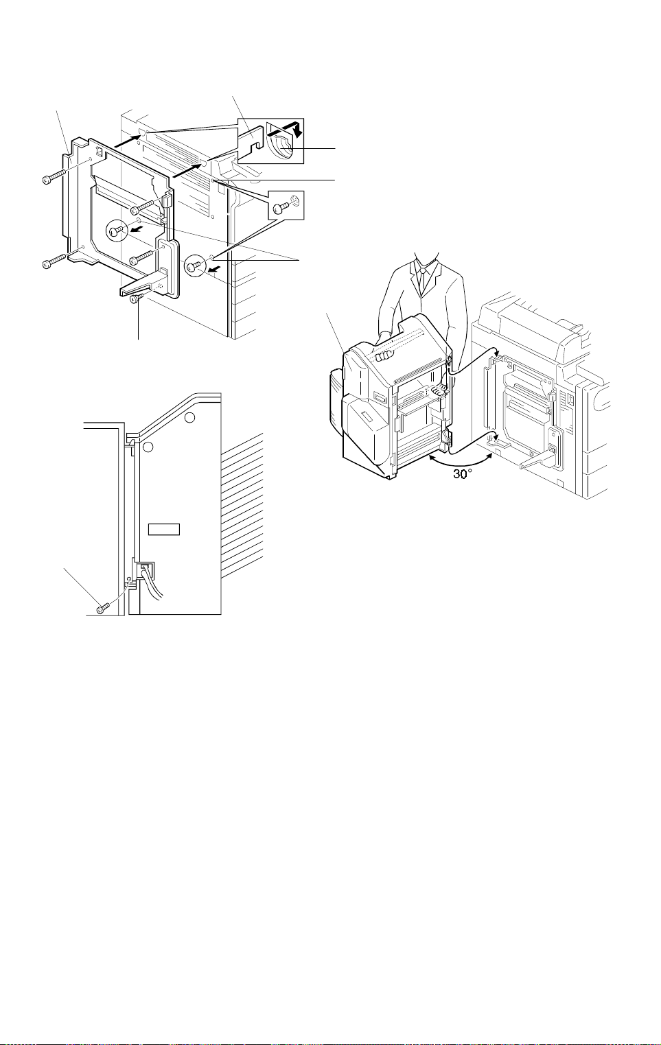
Unplug the copier power cord before star ting the follo wing procedure.
1. Remove the strips of tape [A].
2. Attach the sponge retainer [B] to the top cover of the copier as shown.
3. Tighten the two stud screws [C].
4. Mount the ARDF by aligning the holes [D] in the ARDF and the stud
screws [C], then slide the ARDF to the front as shown.
NOTE:
When mounting the ARDF, hold it by hand as shown in the
illustration. Holding it in another way may damage the ARDF.
5. Screw the two stud screws [E] into the holes [F] and tighten them.
6. Connect the connectors [G] into the socket on the rear of the copier.
7. Attach the symbol explanation decal [H] and the combine originals
explanation decal [I] to the ARDF as shown
(except for the A207 copier).
49
Page 53

INSTALLATION 31 March 1997
11.5 20-BIN SORTER STAPLER (A664) ACCESSORY CHECK
Check the accessories against the following list:
Description Q’ty
1. Front Connection Bracket................................................. 1
2. Rear Connecting Bracket ................................................. 1
3. Cushion ............................................................................ 2
4. Entrance Guide Mylar for A204/A206/A207 copiers ....... 1
5. Entrance Guide Mylar for A208/A210/A211 copiers ....... 1
6. Proof Tray ........................................................................ 1
7. Caster Stopper ................................................................. 2
8. Relay Guide ..................................................................... 1
9. Philips Pan Head Screw - M4 x 12................................... 4
10. Philips Pan Head Screw - M4 x 6..................................... 2
11. New Equipment Condition Report (Multi-language)......... 1
12. Staple Position Decal ....................................................... 1
13. Installation Procedure (English)........................................ 1
50
Page 54

31 March 1997 INSTALLATION
11.6 20-BIN SORTER STAPLER (A664) INSTALLATION
PROCEDURE
[A]
[D]
[A]
[B]
[B]
[A]
[A]
[B]
A664I500.wmf
Copier
[A]
[A]
A664I501.wmf
[E]
[C]
CAUTION
A664I502.wmf
Unplug the copier power cord before star ting the follo wing procedure.
NOTE:
1) Keep the shipping retainers after installing the machine. They will
be reused if the machine will be transported to another location.
2) Proper reinstallation of the shipping retainers is required in order
to avoid any transport damage.
3) A sorter adapter (A568) is required to install this sorter stapler in
the A208/A210/A211 copiers. Before installing this sorter stapler,
please install the sorter adapter.
1. Remove the strips of tape [A] and the cushions [B].
2. Open the front door and remove the inner cover [C] (3 screws).
3. Remove the strips of tape [D] and remove the cushion [E]. Then re-install
the inner cover [C].
51
Page 55

INSTALLATION 31 March 1997
–A204/A206/A207 copiers–
–A208/A210/A211 copiers–
[C]
[A]
–A204/A206/A207 copiers–
[D]
A664I503.wmf
[B]
[C]
[A]
–A208/A210/A211 copiers–
[D]
[B]
A664I504.wmf
[E]
[D]
A664I505.wmf
[D]
A664I506.wmf
4. Remove the two M4 x 8 round head screws [A] from the left cover of the
copier.
5. Install the front connecting bracket [B] (2 screws M4 x 12) and the rear
connecting bracket [C] (2 screws M4 x 12) on the copier.
6. Attach the entrance guide mylar [D] to the copier exit area, as shown.
NOTE:
1) The entrance guide mylar differs depending on the model.
2) Align the edge [E] of the cover and the mylar.
52
[E]
Page 56

31 March 1997 INSTALLATION
[A]
Copier
[D]
[B]
[C]
A664I507.wmf
[H]
[E]
[F]
7. Attach the two cushions [A] as shown.
8. Install the relay guide [B] (2 screws M4 x 6).
[G]
A664I508.wmf
9. Open the front door of the sorter stapler and remove the screw [C]
securing the locking lever [D], then lower the locking lever.
10. Align and press the sorter stapler against the copier and secure them by
raising the locking lever [E].
11. Secure the locking lever (1 screw [F]).
12. Install the proof tray [G].
13. Connect the connectors [H] to the sockets at the rear of the copier.
53
Page 57

INSTALLATION 31 March 1997
[A]
A664I509.wmf
14. If the gap between the top of the sorter stapler and the copier is too great,
adjust it by placing caster stoppers [A].
15. Plug in the copier.
16. Turn on the main switch of the copier and test the operation of the sorter
stapler.
NOTE:
The copier automatically recognizes that the sorter stapler has
been installed.
54
Page 58

31 March 1997 INSTALLATION
11.7 20-BIN SORTER STAPLER (A658) ACCESSORY CHECK
Check the accessories against the following list:
Description Q’ty
1. Staple Position Decal ....................................................... 1
2. Chain ................................................................................ 1
3. Cap Remover ................................................................... 1
4. Philips Pan Head Screw - M4 x 14................................... 5
5. New Equipment Condition Report (Multi-language)......... 1
6. Installation Procedure (English)........................................ 1
7. Stepped Screw ................................................................. 1
Copier
55
Page 59

INSTALLATION 31 March 1997
11.8 20-BIN SORTER STAPLER (A658) INSTALLATION
PROCEDURE
[A]
A658I500.wmf
A658I501.wmf
[C]
CAUTION
[B][D]
A658I508.wmf
Unplug the copier power cord before star ting the follo wing procedure.
When handling the sorter stapler, make sure to hold the parts shown
[A]. Otherwise, the resulting damage may cause paper jams at the
entrance.
NOTE:
1) Keep the shipping retainers after installing the machine. They will
be reused if the machine will be transported to another location.
2) Proper reinstallation of the shipping retainers is required in order
to avoid any transport damage.
3) A sorter adapter (A568) is required to install this sorter stapler in
the A208/A210/A211 copiers. Before installing this sorter stapler,
please install the sorter adapter.
1. Remove the strips of tape and the shipping retainers as shown.
2. Open the front door [B] and remove the cardboard [C] and the strip of
tape [D] from the staple unit. Close the front door.
56
Page 60

31 March 1997 INSTALLATION
Copier
[A]
A658I502.wmf
[B]
A658I503.wmf
3. Remove the two plastic caps [A] from the copier left cover with nippers.
[C]
4. By releasing the open lever [B] of the sorter stapler, remove the sorter
stapler mounting frame [C], as shown.
57
Page 61
INSTALLATION 31 March 1997
[C]
[E]
[F]
[B]
[A]
[G]
[D]
A658I504.wmf
A658I505.wmf
[H]
A658I506.wmf
5. Remove the M4 x 8 round head screws (2 screws [A] for the
A204/A206/A207 copiers
copiers
) from the left cover of the copier.
, 3 screws [A] and [B] for
A208/A210/A211
6. Mount the sorter stapler mounting frame [C] on the copier as shown
(4 screws M4 x 14 and 1 stepped screw [D]).
NOTE:
When hooking the sorter stapler mounting frame on the left side
of the copier, make sure that the positioning hooks [E] on the
frame are properly inserted in the positioning holes [F] in the
copier.
7. Install the sorter stapler [G] on the frame (2 hinge pins at the rear) as
shown.
8. Tighten the M4 x 14 screw [H].
NOTE:
This screw prevents the sorter stapler from falling down.
58
Page 62

31 March 1997 INSTALLATION
[A]
[B]
[D]
Copier
[C]
A658I507.wmf
9. Connect the cable [A] and the optic cable [B].
10. Install the chain [C] as shown.
11. Attach the staple position decal [D], as shown.
12. Plug in the copier.
13. Turn on the main switch of the copier and test the operation of the sorter
stapler.
NOTE:
The copier automatically recognizes that the sorter stapler has
been installed.
59
Page 63

SERVICE PROGRAM MODE 31 March 1997
12. SERVICE PROGRAM MODE
12.1 SERVICE PROGRAM MODE TABLE
1. Items written in
2. Items written in
bold italic letters
are modified service programs.
bold
are newly added service programs.
3. A "†" after the mode name means that copies can be made while in this
SP mode.
4. A "‡" after the setting in the "Settings" column means that the actual
factory setting for this is written on the data sheet in the front cover.
5. A "°" before the mode number means that this mode can be accessed by
sales representatives (
•
6. A "
" before the mode number means that this mode can be accessed by
users using a UP mode (
#
#
→
$
→
→
#
→
#
).
$
). See "UP Mode/SP Mode Cross
Reference Table".
7. In the Function column, comments (extra information) are in italics.
8. In the Settings column, the default values are printed in bold letters.
9. "RDS" means Remote Diagnostic System (not available in these models)
"CSS" means Customer Support System (only available in Japan)
10. Type 1 = A204, A206, and A207 copiers
Type 2 = A208, A210, and A211 copiers
12.1.1 Quick Reference
The following is a quick reference list of the SP Modes.
Mode No. Function
Paper Feed/Pape r Tr ansport/Fusin g
1-001 Registration †
1-003-xxx Paper Feed Timing †
1-008 Misfeed Detection †
1-103 Fusing Idling †
°1-104 Fusing Te m perature Control †
1-105-xxx Fusing Temperature Adjustments †
1-106-xxx Fusing Temperature Display †
1-108
1-801 CPM Do wn Select †
1-902 Jogger Span Adjustment (Side Fe nce) †
1-905 Jogger Span Adjustment (End Fence) †
Forced Start †
60
Page 64

31 March 1997 SERVICE PROGRAM MODE
Mode No. Function
Around the Drum
2-001 Drum Charge Voltage Adjustment (for copying)
2-002-xxx Drum Charge Voltage D i spl ay †
SP
2-003 Drum Charge Voltage Adjustment (for making V
patterns)
2-101-xxx Leading/Trailing Edge Erase Margin Adjust ment †
2-201-xxx Development Bias Adjustments †
2-203 Development B ia s A djustment (for making V
patterns)
SP
2-206-xxx Development Bias Display †
2-207
Forced Toner Suppl y (shown as "Com pulsory Toner Supply" on the
display)
2-208-001 Toner Supply Mode Selection †
2-208-002 Toner Supply Ratio (TD Sen sor Supply Mode) †
2-208-003 Toner Supply Ratio (Fixed Supply Mode) †
2-214 TD Sensor Initial Sett i ng
2-215-xxx TD Sensor Output Display †
2-220 TD Sensor Initial Output Displ ay †
2-222 Toner Supply Ratio (Detect Supply Mode) †
2-301-xxx
Transfer Current Adj ust m ent s †
Factory Use Onl y: Do n ot c hange the settings .
2-801 Developer Agit at i on
2-802 Drum Charge Rol l er Temperatur e †
2-812 Drum Reverse Rotation Adjustment †
2-901 Drum Charg e R o l le r Cleaning Inte rval †
2-902 Not used
Copier
Process Control
3-001 ID Sensor Initial Setting
3-002 ID Sensor Initial Setting Display †
3-103-xxx ID Sensor Output Displa y †
L
3-105 Forced V
3-106 Initial V
3-107 Current V
3-111 Current V
3-112 Forced V
Detection
LP/VLG
LP/VLG
RP/VRG
R
Detection
Display †
Display †
Display †
3-123 Drum Initialize
3-801 Auto Process C ont r o l Mo de Sel ection †
3-901 Free Run (Exposure Lamp Off)
3-902 Forced Process Cont r ol
Optics
4-001 Exposure Lamp Volt age Adjustment †
°4-002 Exposure Lamp Voltage Displ ay †
4-008 Vertical Magn i fication Adjustm ent †
4-011-xxx Lens Horizontal HP Adjustments †
61
Page 65

SERVICE PROGRAM MODE 31 March 1997
Mode No. Function
4-013 Scanner Free Run
4-101 Horizontal Magnification Adjus tm ent †
4-102 Lens Error Corre ction †
4-103 Focus Adjustm ent †
4-201 Auto ADS Gain Adjustment
4-202 ADS Initial Gain Display †
4-203 ADS Actual Gain Display †
4-301 APS Sensor Function Check †
4-302 Optional APS Sensor
(LT version onl y)
†
4-303 APS A5/HLT Detection †
4-901 APS Size Priority (for F4 size) †
•
°4-902 APS 8 k/16 k Detection
(A4 versio ns only)
†
Operatio n
•
°5-001 All Indicators ON †
•
°5-002 Feed Station Priority Sele ct i on †
•
°5-003 APS Priority Selection †
•
°5-004 ADS Priority Selection †
•
°5-013 Counter Up/Down Selection †
•
°5-017 Maximum Copy Quantity (Copy Limit) †
•
°5-019-xxx Paper Size Set †
••
°5-021-xxx Duplex Priority Selection (Energy Star) †
••
°5-022-xxx Energy Star Sel ection †
•
°5-101 Auto Reset Time Setting †
•
°5-102 Auto Energy Saver Time Se tti ng †
•
°5-103 Auto Tray Shift †
°5-104 A3/DLT Double Count †
•
°5-106 Image Density Level Correction (ADS Cor rection) †
•
°5-107-xxx Image Shift Margin Ad j ust ment †
•
°5-108 Edge Erase Margin Adjust m ent †
•
°5-110 Center Erase Margin Adj ust m ent †
°5-113 Coin Lock Installation †
5-115 Duplex Image Shi f t (Back Side Margin ) †
°5-121 T/C (Total Counter) Count Up Timing †
••
°5-122-xxx
5-127
••
°5-305-001 Auto Shut Off Time Setting †
OHP Slip Sheet Mode Selection †
APS Detection †
°5-305-002 Auto Shut Off Selection †
°5-401 User Code Mode †
•
°5-402 User Code Counter Check †
•
°5-404-xxx User Code Co unt er Clear †
•
°5-405 User Code Number Settin g †
•
°5-407-xxx User Code Nu mber Clear †
62
Page 66

31 March 1997 SERVICE PROGRAM MODE
Mode No. Function
°5-408 Numbe r of R egistered User Codes Display †
••
°5-410 User Code Reset Ti me Setting †
°5-501-001 PM Interval Setting †
°5-501-002 PM Interval Setting (PM Alarm Mode Setting) †
5-504 Used in Japan onl y. Do not change th e fa ct ory setting.
5-505 Used in Japan onl y. Do not change th e fa ct ory setting.
°5-507 Used in Japan only. Do not ch ange the factory sett i ng.
5-801 Memory All Cl ear †
5-802-xxx Free Run Mode
5-803 Input Check Mode †
5-804 Output Check M ode
°5-810 SC Reset †
5-811 Used in Japan onl y. Do not change th e fa ct ory setting.
°5-812 Telephone Number Inp ut †
(A207 copier only)
°5-816 Used in Japan only. Do not ch ange the factory sett i ng.
5-817 Used in Japan onl y. Do not change th e fa ct ory setting.
°5-905 APS A4/LT Sideways Prior i ty †
•
°5-906 Manual Staple Reset Ti m e Set ting †
•
°5-907 Cover Mode Select i on †
•
°5-908 Image Shift/Erase Selection †
•
°5-909 10 key Zoom/Size Magnification †
•
°5-910 Guidance Language Setting †
(A207 copier o nl y)
Copier
Peripheral s
•
°6-001 SADF Auto Reset Time Setting †
°6-003 Auto Sort Selection †
°6-005 Blank Co py f or L ast O dd O riginals in Dupl ex †
6-006-xxx DF Registration Adjustment †
6-009 DF Free Run with Pap er
•
°6-010 Auto APS Select (DF) †
•
°6-011 Thick/Thin Original Mode Selection †
°6-101 Sorter Installation †
°6-102 Sorter Stack Limi t †
°6-104 Staple Sheet Lim it †
6-105-xxx Staple Position Adjustm ent †
6-107 Sorter Free Run Mode
Counters
°7-001 Total Operation Time Display †
°7-002 Total Original Counter Display †
Copy Charge Counter for RDS/CSS Display †
°7-003
This is for use with f eat ures that are avail able only in Japan.
However, it does show how many originals have been copied (total
of DF mode + platen mode).
63
Page 67

SERVICE PROGRAM MODE 31 March 1997
Mode No. Function
Initial Copy Counter Setting for RDS/CSS Display †
°7-004
°7-101-xxx Total Copies by Paper Size †
°7-203 Drum Counter †
°7-204-xxx Feed Unit Counter †
°7-205 DF Counte r †
°7-206 Stapler Counter †
°7-301-xxx Total Copies by Magnif i cation †
°7-401 Total Service Call Counter †
°7-402 SC Counter by Ser vi ce Call †
°7-501 Total Ja m Counter (Copies + O riginals) †
°7-502
°7-503 Total Original Jam Counter
°7-504-xxx Total Jams by Location †
°7-505-xxx Total Original Jams by Location †
°7-801-xxx Main ROM Version Display †
°7-803 PM Counter Check †
°7-804 PM Counter Clear
°7-807-001 SC Counter C l ear †
°7-807-002 Copy Jam Counter Reset †
°7-807-003 Original Jam Count er R eset †
°7-808 Counter All C lear
°7-810 Copy Counter Clear
°7-811 DF Counte r Cl ear
°7-816-xxx Feed Unit Counter Clear †
This is for use with f eat ures that are avail able only in Japan.
However, it does show t he total number of co pi es that have been
made.
Total Jams by Paper Size † (
Paper Jam Counter . T he counter is not divided up by Paper Size.)
Note:
This is actually the Total Copy
64
Page 68

31 March 1997 SERVICE PROGRAM MODE
12.1.2 SP Mode Table
Mode No. Function Settings
Registration † Adjusts leading edge regist r at i on. 0 ~ 32
1-001
Paper Feed
Timing †
(0.5 mm per step [Range: –8.0 mm to
+8.0 mm])
Adjusts the pape r feed timing at
registration fo r each paper feed sta tion.
Paper feed timing is in proporti on t o the
amount of paper bending [mm] at
registration.
(0.5 mm per step [Range: –8 mm to + 8
mm])
Defau lt = 16 ‡
0 ~ 32
Defau lt = 16
SP1-003-008:
Do not adju st
this setting.
Copier
1-003-001
to
1-003-008
1-008
1-103
°1-104
Misfeed
Detection †
Fusing Idling †
Fusing
Temperature
Control †
SP Number Without Duplex With Duplex
SP1-003-001 1st tray Duplex
SP1-003-002 2nd tray 1st tray
SP1-003-003 3rd tray 2nd tray
SP1-003- 004 4th tray 3rd tray
SP1-003-005 5th tray 4th tray
SP1-003-006 By-pass By-pass
SP1-003-007 LCT LCT
SP1-003-008 Japan only
Switches misfe ed detection on or off for
test purposes (sensor signals are
ignored). Only one copy can be made at
a time, to prevent damage to the
machine.
Selects the total time for the fusing idling
during machine warm-up. For type 2,
fusing idling st ar t s w hen the detected
temperature reaches the operating
temperature –1 5°C. For type 1, fusing
idling starts when the detected
temperature reaches the operating
temperature.
The longer the se l ect ed fusing idling, the
longer time the m achine takes to reach
the ready condition. After changing the
setting, turn the main switch off and on.
Selects the fusing l amp temperat ur e
control mode.
After selecting the control mode, tu rn the
main switch off and on.
0: OFF
1: ON
0: OFF
1: 60 s
2: 100 s
3: 180 s
4: 300 s
Defau lt = 100 s
(Type 1)
Defau lt = Off
(Type 2)
0: On/Off
Control
1: Phase Control
65
Page 69

SERVICE PROGRAM MODE 31 March 1997
Mode No. Function Settings
170 ~ 190
Defau lt = 185
(Type 1)
Defau lt = 180
(Type 2)
1-105-001
Fusing
Temperature
Adjustment
(Main Fusing
Lamp) †
Adjusts the temp er ature of the main
fusing lamp, which heats the central area
of the ho t r oller.
The selected te m perature is displa yed in
the reduce/enlarge indicator.
(1°C per step [Range: 170°C to 190°C])
Fusing
Temperature
Adjustment for
Energy Saver
Adjusts the temp er ature of the fusing unit
in energy saver mode.
(SP5-102 and SP5-305 are a lso related
to Energy Saver Mode.)
Defau lt = 1
(NA)
Defau lt = 0
(Others)
Mode †
SP Setting Type 1 Type 2
1-105-002
0 185°C 175°C
1 170°C 145°C
The lower the fusing temperature is, the
greater the energ y saving ratio is and the
longer the waiting time until the copier
returns to the ready condition.
170 ~ 190
Defau lt = 175
1-105-003
(Type 2
only)
Fusing
Temperature
Adjustment
(Secondary
Adjusts the temp er ature of the
secondary fusing lamp, which heats both
ends of the hot roller.
(1°C per step [Range: 170°C to 190°C])
Fusing Lamp) †
1-106-001
1-106-002
(Type 2
only)
1-108
Fusing
Temperature
Display (Main
Fusing Lamp) †
Displays the temperature (°C) at the
surface of the central area of the hot
roller, as measured by the therm istor.
The temperature in energy savi ng mode
cannot be displayed, as enterin g SP
mode takes the machine out of this
mode.
Fusing
Temperature
Display
(Secondary
Fusing Lamp) †
Displays the temperature (°C) at the
surface of the ends of th e hot roller, as
measured by the the rm i stor.
The temperature in energy savi ng mode
cannot be displayed, as enterin g SP
mode takes the machine out of this
mode.
Forced Start † Selects whether forc ed st art is on or off.
If forced start is switched on, the copier
enters the ready condition even if the
fusing temperature has not reached the
required value yet. Use this for tests if
the room temper at ur e i s l ow and you do
not wish to wait for the lamps to warm up.
0: OFF
1: ON
66
Page 70

31 March 1997 SERVICE PROGRAM MODE
Mode No. Function Settings
1-801
CPM Down
Select †
(Type 1 only)
If this is set to 1 or 2, the machine drops
the cpm to the same as the Type 2
model if it detects a temperature l ow er
than the setting. This allows the roller to
warm up again, to pr event poor fusing .
0: OFF
1: 160 °C
2: 170 °C
This feature may be needed in ar eas
where the main s voltage is a bit low er
than the rating (fo r example, in areas of
Europe where the mains is 210 V,
instead of 220 - 240 V).
1-902
Jogger Span
Adjustment
(Side Fence) †
Adjusts the stop position of the jogger
side fence span of th e duplex unit.
(0.5 mm per step [Range: –8.0 mm to
0 ~ 32
Defau lt = 16
+8.0 mm])
A207 and A211 copiers only
1-905
Jogger Span
Adjustment
(End Fence) †
Adjusts the stop position of the jogger
end fence span of th e duplex unit.
(0.5 mm per step [Range: –8.0 mm to
0 ~ 32
Defau lt = 16
+8.0 mm])
A207 and A211 copiers only
2-001
Drum Charge
Voltage
Adjustment
(for copying) †
Adjusts the voltage appli ed to the drum
charge roller d ur i ng copying.
The adjustment factor set with this SP
mode is added to the base voltage.
0 - 32
Defau lt = 16
(0 V) ‡
(30 V per step [Range: Base voltage
–480 V to Base voltage + 48 0 V])
Drum Charge
Voltage Display
†
2-002-001
to
2-002-002
Displays the vo l ta ge applied to the drum
charge roller.
SP2-002-001: For copying
SP2-002-002: For making V
SP
patterns
The first three d i gi t s ar e di splayed in the
reduce/enla rg e i ndi cator. The actual
value is the disp l ayed value x (–10) V.
Just after the main switch is turned on,
the initial setting voltage is displayed.
After one or more co pi es, the actual
applied volta ge (including the p ro cess
control correc tions) is displ ayed.
Adjusts the voltage appli ed to the drum
charge roller wh en making V
The adjustment factor set with this SP
SP
mode is added to the base voltage.
(10 V per step [Range: Base voltage
SP
patterns.
0 - 32
Defau lt = 16
(0 V) ‡
2-003
Drum Charge
Voltage
Adjustment
(for making V
patterns) †
–160 V to Base voltage + 16 0 V])
Copier
67
Page 71

SERVICE PROGRAM MODE 31 March 1997
Mode No. Function Settings
2-101-001
to
2-101-002
Leading/
Trailing
Edge Erase
Margin
Adjustment †
Adjusts the leading and trailing edge
erase margins.
SP2-101-001: Leading edge erase margi n
SP2-101-002: Traili ng edge erase margi n
(0.5 mm per step [Range: 0.0 mm to
+16.0 mm])
0 - 32
Defau lt = 16
(SP 2-101-001)
Defau lt = 18
(SP-101-002)
‡ (only 2-101001 is on the
data sheet)
2-201-001
2-201-002
2-203
2-206-001
to
2-206-002
2-207
Development
Bias Adjustment
(for copying) †
Lightest ID
Level
Development
Bias
Adjustment †
Development
Bias
Adjustment
(for making
V
patterns) †
SP
Development
Bias Display †
Forced Toner
Supply (shown
as "Compulsor y
Toner Supply"
on the display)
Adjusts the development bias for copying
to make copies lighter or darker in
general.
The adjustment factor set with this SP
mode is applied to the base voltage.
(20 V per step [Range : Base vol t age –80
V to Base voltage +80 V])
Adjusts the development bias for manual
ID level 7.
The adjustment factor set with this SP
mode is applied to the base voltage
when ID level 7 is selected.
Adjusts the development bias for making
SP
V
patterns
The adjustment factor set with this SP
mode is added to the base voltage.
(20 V per step [Range : Base vol t age –80
V to Base voltage + 100 V])
Displays the de vel opment bias.
SP2-206-001: Development bias used
for copying.
SP2-206-002: Development bias used
for making V
SP
sensor
patterns.
The first two digits are displaye d in the
reduce/enla rg e i ndi cator. The actual
value is: displayed value x (–10) V. All
process control corrections are included
in the displaye d val ue.
Forces the toner bot t l e to supply toner to
the toner supply unit for 30 second s.
This mode is star t ed by pressing the
!
key and stops autom atically after a bout
30 seconds. Press t he
#
key to
interrupt if necessary. This SP mode
must be performed twice when installing
the machine and when installing a new
toner supply un i t.
1 - 9
Defau lt = 5
(0 V)
1: Darkest
9: Lightest
1:–40 V
2:±0 V
3: –80 V
4: –120 V
1 - 10
Defau lt = 6
(0 V)
68
Page 72

31 March 1997 SERVICE PROGRAM MODE
Mode No. Function Settings
1: TD sensor
supply mode
2: Fixed supply
mode
3: Detect
supply mode
1: 7%
2: 15%
3: 30%
4: 60%
1: 3%
2: 6%
3: 10%
4: 15%
!
2-208-001
2-208-002
2-208-003
2-214
Toner Supply
Mode Selection
†
Toner Supply
Ratio
(TD Sensor
Supply Mode) †
Toner Supply
Ratio
(Fixed Supply
Mode) †
TD Sensor
Initial Setting
Selects the toner supply mode.
In many cases, the machine will change
the toner supply m ode automatic al l y i f
either the TD or ID sensor become
unreliable. H ow ever, sometim es i t d oes
not.
If the TD sensor fai ls, you can select
fixed supply mode as a temporary
measure.
If the ID sensor fail s, you can select TD
sensor supply mode.
After repairing the ma chi ne, check
whether the toner supply mode ha s gone
back to the detect supply mode.
Selects the toner supply ratio for TD
sensor supply mode.
For example, if the user normally makes
copies of originals that are about 7%
black, select the 7% setting for best
results.
Selects the toner supply ratio for Fixed
Supply Mode.
For example, if the user normally makes
copies of originals that are about 6%
black, select the 6% setting for best
results.
Performs the TD sensor initial setting.
This SP mode controls the voltage
applied to the TD sensor to make the TD
sensor output 2.5 ± 0.1 V.
After using SP2-214, ch eck SP2-220 to
see if the sensor is working correctly.
This mode is star t ed by pressing the
key and stops autom atically after a bout
2.5 minutes. Use this mode only after
adding new developer.
2-215-001
to
2-215-002
2-220
TD Sensor
Output Displa y †
TD Sensor
Initial Output
Display †
Displays the TD sensor output vol t age.
SP2-215-001: VT = Current TD sensor
output
SP2-215-002: V
Displays the TD sensor initial setting
output (after doing SP2- 214).
TREF
= Reference TD
sensor output
Normally, 2.5 ± 0.1 V is displaye d.
[Range: 0 V to 5.0 V]
If it is not, the sensor m ay be defective .
Copier
69
Page 73

SERVICE PROGRAM MODE 31 March 1997
Mode No. Function Settings
2-222
2-301-001
to
2-301-002
Toner Supply
Ratio
(Detect Suppl y
Mode) †
Transfer Current Adj ust m ent s †
Factory Use Onl y: Do n ot c hange the settings .
Selects the toner supply ratio for det ect
supply mode.
For example, if the user normally makes
copies of originals that are about 7%
black, select the 7% setting for best
results.
1: 7%
2: 15%
3: 30%
4: 60%
0 ~ 32
15 (–35 µA):
Type 1
14 (–30 µA):
Type 2
Developer
Agitation
2-801
After the ! key is pressed, the
developer is agitated. To stop, press the
key.
$
Use this SP mode if th e m achine has not
been used for a lon g time.
2-802
2-812
Drum Charge
Roller
Temperature †
Drum Reverse
Rotation
Adjustment †
Displays the drum charge roller
temperature [0 ~ 60 °C].
Adjusts the amount of the time for the
drum reverse rot at i on after each copy j ob.
If paper dust rem ai ns on the drum, it m ay
get into the recyc l ed t oner. If this is
happening, increase the reve rs e rotation
by increasin g th e val ue of the setting.
Drum Charge
Roller
Cleaning
Interval †
2-901
Selects the drum charge rol l er cleaning
interval.
Turn the copier m ai n sw i t ch off and on
after changing t he setting.
The drum charge roller is cle aned briefly
at the end of each cop y j ob. The drum
charge roller is also cleaned for 5
seconds after the i nt er val selected w i th
this SP mode.
2-902 Do not use —
3-001
ID Sens o r Initi al
Setting
Performs the ID sensor initial setting. ID
sensor output for the bare area of the
drum (V
SG
) is adjusted to 4.0 ± 0.2 V.
To start this SP mode, press the ! key.
3-002
ID Sens o r Initi al
Setting Display
†
Displays the initial setting value of the ID
sensor.
Normally 4.0 ± 0.2 V is displayed. If the
ID sens or cannot be adjust ed to 4.0
0.2 V, the ID sensor or the O P C dr um
should be cleaned.
0 ~ 32
Defau lt = 16
(about 3 mm)
0: Every 1,000
copies
1: E very 500
copies
2: Every 200
copies
3: Every 100
copies
±
70
Page 74

31 March 1997 SERVICE PROGRAM MODE
Mode No. Function Settings
3-103-001
to
3-103-002
ID Sens o r
Output Displa y †
Displays the ID sensor outputs.
SP3-103-001: V
SP3-103-002: V
SP
SG
Normally, VSP = 0.01 ~ 2.50 V, VSG =
4.0 ± 0.2 V (VSP/VSG ≈ 0.1)
L
After the ! key is pressed, the initial
LP/VLG
V
(= V
REF
) is determined.
3-105
Forced V
Detection
For when to use this SP mo de, see
"Practical SP Mode U se Table".
3-106
3-107
Initial V
LP/VLG
Display †
Current
LP/VLG
V
Display †
Current
VRP/V
RG
Display †
Displays the initial V
determined by SP3-105.
Displays the cu rrent VLP/VLG value [%].
This is the value currently being used for
L
correction.
V
Displays the cu rrent V
This is the value currently being used for
R
correction.
V
LP/VLG
RP/VRG
value
value [%]
Copier
3-111
3-112
3-123
RP/VRG
V
100 (%)
Forced V
Detection
ID Correction
0 V
±
74 ~ 100 68 ~ 100 62 ~ 100
53 ~ 73 50 ~ 67 43 ~ 61 –40 V –40 V
x
41 ~ 52 37 ~ 49 26 ~ 42 –80 V –80 V
31 ~ 40 26 ~ 36 19 ~ 25 –120 V –120 V
0 ~ 30 0 ~ 25 0 ~ 18 –160 V –160 V
R
–40 V –80 V
After the ! key is pressed, for ced V
detection is don e.
Drum Charge Roller
Correction Voltage
0 V
±
For when to use this SP mo de, see
"Practical SP Mode U se Table".
Drum Initialize This resets the following data regarding
the OPC drum:
R
correction level
1. V
L
correction le vel
2. V
3. OPC counter
4. T/H correction level
This SP mode must be used only
when a new drum is installed.
Refer to
"Practical SP Mode U se Table" for the
exact timing for usi ng this SP mode.
Development Bias
Correction Voltage
±
R
0 V
71
Page 75

SERVICE PROGRAM MODE 31 March 1997
Mode No. Function Settings
0: OFF
1:1,000 copies
2: 500 copies
3: 200 copies
3-801
Auto Process
Control Mode
Selection †
Selects whether aut o process control
mode is off or performed at the interval
shown.
If the auto process control mode is
switched off, V
R
correction, V
L
correction, an d th e 1, 000-copy process
control cycle will not be performed.
This SP mode can be used to help
determine wh et her a copy quality
problem is caused by process control or
by the machine itself.
Free Run
(Exposure
Lamp Off)
3-901
Performs a free run w i t h th e exposure
lamp off.
Start the free run b y pr essing the
!
key and stop it by pressing the $ key.
Be sure to perform this mode without
a development un it, o r t oo m uch toner
will be consumed from the developer,
causing low imag e density.
Forced Process
Control
3-902
Performs the 1,0 00- copy process cont rol
cycles forcibly.
SG
V
initial adjustment → VR detect i on
L
detection → V
V
ADS
(pattern)
→
adjustment
This mode start s af te r t he ! key is
pressed.
Exposure Lamp
Voltage
Adjustment †
Adjusts the exposure lamp voltage
(0.5 V per step [Range: 50. 0 V to 7 5. 0 V])
For 115 V machines, the a ctual applied
50.0 ~ 75.0 V
Defau lt = 63 V
‡
voltage = displayed value x 1.14 12.
After doing this SP mode, ADS initial
4-001
setting (SP4-201) and forced V
L
detection (SP3-105) must also be
done.
See "Replaceme nt and Adjustme nt Copy Quality Adjustments" for how to
adjust.
°4-002
Exposure Lamp
Voltage Display
†
Displays the cu rrent exposure lam p
voltage.
(0.5 V per step [Range: 50. 0 V to 8 5. 0 V])
50.0 ~ 85.0 V
For 115 V machines, the a ctual applied
voltage = displayed value x 1.14 12.
0 ~ 32 V
Defau lt = 16 ‡
4-008
Vertical
Magnification
Adjustment †
Adjusts the magni f i cation in the pap er
travel direction.
(0.1% per step [Range: –1.6% to +1.6%])
See "Replacement and Adjustme nt Copy Quality Adjustments" for how to
adjust.
72
Page 76

31 March 1997 SERVICE PROGRAM MODE
Mode No. Function Settings
Lens Horizontal
HP Adjustment
†
Adjusts the lens horizontal hom e position
for each paper feed st ation.
(0.2 mm per step [Range: –3.2 mm to
+3.2 mm])
0 ~ 32 V
Defau lt = 16 ‡
(only 4-011008 is on the
data sheet)
SP Number Without Duplex With Duplex
4-011-001 1st tray Duplex
4-011-002 2nd tray 1st tray
4-011-003 3rd tray 2nd tray
4-011-00 4 4th tray 3rd tray
4-011-005 5th tray 4th tray
4-011-001
to
4-011-009
4-011-006 By-pass By-pass
4-011-007 LCT LCT
4-011-008 Base Adjustment
4-011-009 ADF ADF
SP4-011-008 changes the home pos i tion
for all paper feed st at i ons at the same
time. It is mainly used for making factory
adjustments. If it is shifted by a cert ai n
amount, all other SP4-011 adjust m ent s
move by the same amount.
See "Replaceme nt and Adjustme nt Copy Quality Adjustments" , and
"Side-to-side Registration" in the ARDF
manual for deta i l s on how to adjust.
4-013
4-101
Scanner Free
Run
Horizontal
Magnification
Adjustment †
Starts the scanner free run.
Start the scanner f re e run by pressing
!
the
$
key, and stop it by pressing the
key.
Adjusts the magni f i cation perpendi cular
to the direction of paper travel.
(0.1% per step [Range: –1.6% to +1.6%])
See "Replacement and Adjustme nt -
0 ~ 32
Defau lt =16 ‡
Copy Quality Adjustments" for how to
adjust.
4-102
Lens Error
Correction †
Focus
Adjustment †
Adjusts the lens position to correct for
magnificati on i n enlarge/redu ce m ode.
(0.1% per step [Range: –0.8% to +0.8%])
Adjusts the 3rd mirror position to correct
the fine focus.
0 ~ 16
Defau lt = 8
(0%) ‡
30 ~ 150
Defau lt = 75 ‡
(0.05 mm per step [Range: le f t 3.75 mm
4-103
to right 3.75 mm])
See "Replacement and Adjustme nt Copy Quality Adjustments" for how to
adjust.
Copier
73
Page 77

SERVICE PROGRAM MODE 31 March 1997
Mode No. Function Settings
Auto ADS Gain
Adjustment
4-201
Adjusts the ADS gain automatically to
make the sensor output 2.7 ± 0.1 V.
Close t he platen cover to prevent
external lig ht from reaching the ADS
sensor. Then p re ss t he
!
key to make
the adjustment .
4-202
4-203
ADS Initial Gain
Display †
ADS Actual
Gain Display †
APS Sensor
Function Check
†
Displays the ADS sensor output adjust ed
by SP4-201.
Displays the cu rrent ADS sensor outpu t.
Check the APS sensors.
If they are workin g cor r e ct l y, th e
following value is displayed in the
reduce/enlarge indicator.
LT version:
0 or 95
(without
optional APS)
0 or 127
(with optional
APS)
A4 version:
0 or 95
4-301
ADF/Platen
Open
ADF/Platen
Closed
LT Version
Without
optional
APS
000
95 127 95
With
optional
APS
A4
Version
4-302
4-303
4-901
Optional APS
Sensor †
(LT version
only)
APS A5/HLT
Detection †
APS Size
Priority
(for F4 size) †
Set this to 1 when installing the optional
APS sensor.
This SP mode is effecti ve only for the LT
version. In the A4 ve rs i on, even if "1" is
selected, the setting is ignored.
Selects whether A5/H LT f or ced detection
is done or not.
If "YES" is selected, paper sizes that
cannot be detected by the APS sensors
are regarded as A5 lengthwise (for A4
models) or 5
1/2
" x 8
1/2
" (for LT models).
If "NO" is selected, "Check Paper Si ze"
will be displayed.
Selects which co py paper size the
machine selects when the APS sensors
detect F4 lengthwise (8
1/2
" x 13").
0:Not installed
1: Installed
0: NO
1: YES
0: 8
" x 13"
1/2
1: 8" x 13"
1/4
2: 8
" x 13"
74
Page 78

31 March 1997 SERVICE PROGRAM MODE
Mode No. Function Settings
APS 8 k/16 k
Detection †
(A4 vers ions
only)
Selects whether the machine can sel ect
8 k/16 k copy paper based on APS
sensor readin gs.
If "YES" is selected, 8 k/16 k copy paper
0: NO
1: YES
is selected under the following conditions:
Copier
•
°4-902
•
°5-001
•
°5-002
All Indicators
ON †
Feed Station
Priority
Selection †
Size detected by
APS
B4 lengthwise
A4 lengthwise
B5 sideways
Selected copy paper size
8 k lengthwise
(267 mm x 390 mm)
16 k lengthwise
(267 mm x 195 mm)
16 k sideways
(115 mm x 267 mm)
If "YES" is selected, the duplex end
fence must be removed to allow the 8 k/
16 k movement of the jogger fences.
Turns on all indicators on the oper at i on
panel for 10 seco nds. It can be manuall y
turned off by press i ng t he # key.
Selects the paper feed station priority. 1 ~ 6:Non
duplex
Setting
1 1st Tray 1st Tray
2 2nd Tray 2nd Tray
3 3rd Tray 3rd Tray
4 4th Tray 4th Tray
5 5th Tray LCT
6LCT —
Non duplex
machines
Duplex machines
machines
1 ~ 5:Duplex
machines
Defau lt = 1
(without LCT)
Defau lt = LCT
(with LCT)
(5 or 6)
•
°5-003
•
°5-004
•
°5-013
•
°5-017
APS Priority
Selection †
ADS Priority
Selection †
Counter
Up/Down
Selection †
Maximum Copy
Quantity (Copy
Limit) †
Specifies whether the copier defaults to
APS or manual mode when the main
switch is turned on, auto reset, or mode
cleared.
Specifies whether the copier defaults to
ADS or manual ID mode w hen the main
switch is turned on, auto reset, or mode
cleared.
Selects whether the counter counts up or
down.
Limits the maximum copy quantity that
can be entered.
75
1: APS
2: Manual
Also see
SP6-010.
1:ADS
2: Manual
1: Up
2: Down
1 ~ 999
Defau lt = 999
Page 79

SERVICE PROGRAM MODE 31 March 1997
Mode No. Function Settings
•
°5-019-001
to
5-019-008
••
°5-021
Paper Size Set†Sets the paper size f or ea ch paper tray
and feed station.
Duplex Priority
Selection
Specifies whether the copier defaults to
duplex or singl e si ded copies mod e.
(Energy Star) †
For how to
input the
settings, see
sectio n 2.7.
1: Duplex
2: Single side
Defau lt = 1
(NA)
Defau lt = 2
(Others)
°5-022
•
°5-101
Energy Star
Selection †
Auto Reset
Time Setting †
Specifies whether the copier perf or ms
the modes which are related to the
Energy Star Standardization.
The following SP modes are changed
automatically when this setting is
changed.
SP1-105-002
•
SP5-021
•
SP5-102
•
SP5-305-001
•
SP5-305-002
•
Inputs the auto res et time after the copier
enters standby, or di sables auto reset .
0: NO
1: YES
Defau lt = 1
(NA)
Defau lt = 0
(Others)
0 ~ 999
Defau lt = 60
(1 second per step [Range: 1 ~ 999])
If "0" is selected, auto reset is disabled.
•
°5-102
•
°5-103
°5-104
Auto Energy
Saver Time
Setting †
Sets the time that the machine enters
energy saver mode after enteri ng t he
ready condition.
(1 minute per st ep)
If "0" is selected , t he energy saver mode
is disabled (ex cept for NA version).
Auto Tray Shift†Selects whether aut o t ray shift is on or
off.
A3/DLT Double
Count †
Specifies whether the counter is doubled
for A3/DLT paper.
If "ON" is selected, the total counter and
NA version
1 ~ 120
Default = 15
Other version s
0 ~ 120
Default = 1
0: OFF
1: ON
0: OFF
1: ON
the current user code counter cou nt s up
twice when A3/DLT copy paper is used.
•
°5-106
Image Density
Level
Correction
(ADS
Correction) †
Selects the image density level
correction.
The development bias voltage correction
in ADS mode depends on this setting
(see "ADS Correction" in the Process
0: Darkest
1: Darker
2: Normal
3: Lighter
4: Lightest
Control section for details).
76
Page 80

31 March 1997 SERVICE PROGRAM MODE
Mode No. Function Settings
A4 version
0 ~ 15
Default = 5
LT version
0 ~ 0.60
Default = 0.20
•
°5-107-001
to
5-107-004
Image Shift
Margin
Adjustment †
This controls the l ef t a nd r i ght m argin
width adjustm ent for both 1st and 2nd
side copies.
SP5-107-001: Left Margin (1st side)
SP5-107-002: Right Margin (1st side)
SP5-107-003: Left Margin (2nd side)
SP5-107-004: Right Ma rg i n (2nd side)
SP5-908 must be at 2 for this to have
any effect; this changes the functi on of
the Erase key to a Margin Adjustment
key.
A4 version: 1 mm per step
[Range: 0 mm to 15 mm ]
LT version: 0.01" per step
[Range: 0" to 0.60"]
•
°5-108
•
°5-110
Edge Erase
Margin
Adjustment †
Center Erase
Margin
Adjustment †
Adjusts the edge erase margin width in
erase edge mode.
SP5-908 must be at 1 for this to have
any effect. A strip of th e sel ected width
will be erased around the edges of the
copy image.
Adjusts the center er ase margin widt h i n
erase center mode.
SP5-908 must be at 1 for this to have
any effect.
A4 version: 1 mm per step
Range: 8 mm to 25 mm]
A4 version
1: 5 mm
2: 10 mm
LT version
1: 0.20"
2: 0.40"
A4 version
8 ~ 25
Default = 20
LT version
0.32 ~ 1.00
Default = 0.80
LT version: 0.01" per step
[Range: 0.32" ~ 1. 00" ]
°5-113
5-115
Coin Lock
Installation †
Duplex Image
Shift †
(Back Side
Margin)
Specifies whether coin lock is installed or
not (only for Japa nese versions).
Specifies whether duplex ima ge shift
(back side margi n) is used or not.
If "YES" is selected, a 5 mm margin is
made on the rig ht of the reverse side o f
copies when making two-sided copies
0:Not installed
1: Installed
0: NO
1:YES
from one-side d originals.
If the image shift mode has been
selected with SP5- 908 and if the user
uses image shift mode, this SP mode
has no effect.
°5-121
T/C (Total
Counter) Coun t
Determines whether the total counter
counts up at paper fee d or at paper exit.
0: Feed
1: Exit
Up Timing †
••
°5-122
OHP Slip
Sheet Mode
Selects whether to have a image on the
OHP slip sheet or not.
0: Blank
1: Image
Selection †
5-127
APS Detection
†
Selects whether APS detection is done
or not.
0: NO
1:YES
Copier
77
Page 81

SERVICE PROGRAM MODE 31 March 1997
Mode No. Function Settings
•
5-305-001
°
Auto Shut Off
Time Setting †
Selects the auto shut off time in
one-minute st eps.
The copier main switch is shut off
automaticall y af t er the selected aut o shut
off time if SP5-305-002 is set to 0.
NA version
1 ~ 120
Default = 60
Other version s
1 ~ 999
Default = 60
•
5-305-002
°
°5-401
•
°5-402
•
°5-404-001
to
5-404-002
•
°5-405
Auto Shut Off
Selection †
User Code
Mode †
User Code
Counter Check
†
User Code
Counter Clear †
User Code
Number Setting
†
Selects the "Automat ic Shut Off" mode. 0 :YES
The copier auto matically shuts i t sel f off
at the auto shut off time selected
(SP5-305-001).
1: NO
Defau lt = 0
(NA)
Defau lt = 1
(Others)
After JP101 on the main board is cut,
either key counter mode or user code
0: K ey Counte r
1: User Code
mode can be selected with this SP mode.
Displays the user code counters.
The current user code is displayed in
copy counter, and the copy count for that
user code is displ ayed in the
reduce/enla rg e i ndi cator. Hold dow n t h e
"•" key to display the last three digits.
Use the
9
and : keys to check ea ch
user code counter .
Resets the user code counters.
SP5-404-001: Resets the counter for the
user code that is no w
displayed in the
reduce/enlarge indicator.
SP5-404-002: Resets all t he U C counters.
To reset the counter(s),
press the % key.
SP5-404-001: The user code mus t be
input at the num eric keys
before it can be displayed
and the counter reset, so
you must know what user
codes are in use. Take a
look with SP5-405.
Use this mode to in put th e user code
numbers (max. 3 digits).
1 ~ 999
(max. 50 code s)
Up to 50 user codes c an be set. To input
a code, enter it at the numeric keys t hen
press the
%
key. Then you can input
another. To check the user codes input
so far, use the
9
and : keys. The user
codes input will be displayed in
reduce/enla rg e counter.
78
Page 82

31 March 1997 SERVICE PROGRAM MODE
Mode No. Function Settings
User Code
Number Clear †
Deletes user code numbers.
SP5-404-001: Deletes individual use r
code numbers. Enter the
•
°5-407-001
to
5-407-002
required us er code at the
numeric ke ys, th en press
the % key. (To see which
user codes are being used,
use SP5-405.)
SP5-404-002: Deletes all t he user code
numbers.
°5-408
Number of
Registered
User Codes
Displays the nu m ber of registered user
codes in the redu ce/ enlarge indicat or.
Display †
•
5-410
°
User Code
Reset Time
Setting †
Selects the user code reset time in
one-second steps. This is the tim e th at
the current user co de remains active
1 ~ 999
Defau lt = 60
after the end of the copy job.
°5-501-001
PM Interval
Setting †
Sets the PM interval.
(1,000 copies per step [Range: 1 to 999])
1 ~ 999
120: Type 1
100: Type 2
0: OFF
1: ON
°5-501-002
PM Interval
Setting
(PM Alarm
Mode Setting) †
Specifies whethe r PM al ar m mode is on
or off.
If PM alarm mode is on , the manual ID
level/ADS indicator and copy counter
blink when the PM counter reache s the
PM interval.
5-504
RDS/CSS Alarm Level fo r Pap er Jam (Paper Jam Alar m Level Setting) †
Used in Japan only. Do not change th e factory setting.
Copier
5-505
°5-507
5-801
RDS/CSS Alarm Level fo r SC (Service Call Alarm Level Setting) †
Used in Japan only. Do not change th e factory setting.
RDS/CSS Alarm Level for Supplies (Supply Alarm Mode Setting) †
Used in Japan only. Do not change th e factory setting.
Memory All
Clear †
Resets all the correction data for process
control and all sof t w are counters, and
returns all modes and adjustments to the
default setting s.
See Service Tables - section 2.2.4 for
how to perform this SP mode.
Normally, this SP mode should not be
performed.
This SP mode is required only when
replacing the RA M board, or when the
copier malfu nct i ons due to a damaged
RAM board.
79
Page 83

SERVICE PROGRAM MODE 31 March 1997
Mode No. Function Settings
Free Run Mode Performs the free run
SP5-802-001: Continuo us f ree run
5-802-001
to
5-802-002
SP5-802-002: One time free r un
Before starting, cl ose the platen or
ARDF. Press the
free run. Press the
!
key to start the
$
key to stop the
free run.
5-803
Input Check
Mode †
Displays the da ta received from se nsors
and switches.
For details, see
Service Tables
sectio n 2-5.
5-804
Output Check
Mode
Turns on the electrical components
individuall y fo r t est pur poses.
For details, see
Service Tables
- section 2-6.
SC Reset † Res ets any service call condition that
was caused by a lev el A e rror (see the
°5-810
Troubleshooting section).
After doing SP5-810, tur n th e copier
main switch off and on.
5-811
Machine Serial N o. Input †
For use with features that are available in Japan on ly
°5-812
°5-816
5-817
°5-905
•
°5-906
Telephone
Number Input †
(A207 copier
only)
Use this to input the t el ephone number
of the ser vice representative (this is
displayed when a service call condition
occurs.) Maxim um 16 di gits. Press the "
key to input a pause (–).
Press the # key to delete the input
telephone number.
RDS/CSS Function Setting †
For use in Japan onl y. Do not change th e fa ct ory setting.
Repair Time Transmission †
For use in Japan onl y. Do not change th e fa ct ory setting.
APS A4/LT
Sideways
Priority †
Specifies whether the machine sel ects
LT sideways paper if the original is A4.
If "ON" is selected, LT sideways copy
paper is selected automatically when the
APS sensors detect an A4 sideways
original. Thi s fe ature does not work i n
reverse (A4 sideways paper is not
selected for an LT sideways original).
Manual Staple
Reset Time
Setting †
Sets the manual stapl e reset time.
(1 second per step [Range: 1 to 999])
After the end of a copy jo b in sort mode,
manual staple mode is reset
automaticall y w hen the manual st apl e
reset time has passed.
"
•
0: OFF
1: ON
1 ~ 999
Defau lt = 20 s
80
Page 84

31 March 1997 SERVICE PROGRAM MODE
Mode No. Function Settings
•
°5-907
Cover Mode
Selection †
Used to select whet her to have front
cover, front and back covers, or front
cover with image and back cover blank
image added to copies in cover mode.
Copy paper for the c over pages shoul d
1: Front/Back
2:Front
3: Front with
Image/Back is
blank
be placed on the by- pass feed table.
•
°5-908
Image
Shift/Erase
Selects whether to have an image shift
mode or an image erase mode.
1:Erase mode
2: Shift mode
Selection †
•
°5-909
10 key
Zoom/Size
Magnificati on †
Selects whether to have a 10 key zoom
function or a siz e m agnification function.
1:Size
magnification
2: 10 key zoom
function
•
°5-910
Guidance
Language
Setting †
(A207 copier
only)
Selects the language used on the
operation pan el di splay (except fo r SP
mode gui dance).
1: Englis h
2: Fre nch
3: German
4: It al i an
5: Spanish
6: Swe dish
7: Portuguese
8: Dani sh
9: Norwegian
10: Finnish
11: Dutch
•
°6-001
°6-003
SADF Auto
Reset Time
Setting †
Auto Sort
Selection †
Sets the auto reset tim e fo r SADF m ode.
(1 second per step [Range: 1 to 99
seconds])
Specifies whether auto sort mod e i s on
or off.
In auto sort mode, w hen two or more
originals are pl aced on the ADF, so rt
1 ~ 99
Defau lt = 5
0: OFF
1: ON
mode is selected if the copy quanti t y i s
between 2 and 20.
°6-005
Blank Copy for
Last Odd
Originals in
Duplex †
Specifies whether a blank copy is added
after the last page f or a n odd number of
originals in duplex mode.
In SADF or platen mode, the last page
always stays in the duplex unit,
0: Not added
(the last page
stays in the
duplex unit)
1: Added
regardless of th i s set t i ng.
DF Registration
Adjustment †
Adjusts the registrati on of the doc ument
feeder.
0 ~ 32
Defau lt = 16
SP6-006-001: One-sided original
6-006-001
to
6-006-002
SP6-006-002: Two-sided original
(0.3 mm per step [Range: –4.8 mm to
+4.8 mm])
See "Vertical Registration" in the ARDF
manual for deta i l s on how to use these
adjustments.
Copier
81
Page 85

SERVICE PROGRAM MODE 31 March 1997
Mode No. Function Settings
6-009
DF Free Run
with Paper
To start the DF free r un, put som e
sheets of paper on the ARDF then press
the ! key. Stop the free run by
pressing $ key.
This is a genera l fr ee r un controlled fro m
the copier. For mo r e detailed free run
modes, see the manual for the DF .
•
°6-010
Auto APS
Select (DF) †
Selects whether auto APS mode is used
with th e DF or not.
If "ON" is selected, APS mode is
selected automatically when an original
0: OFF
1: O N
is placed on the DF . Th is SP mode is in
effect only when the APS priority
(SP5-003) is set to Ma nual.
•
°6-011
°6-101
Thick/Thin
Original Mode
Selection †
Sorter
Installation †
Selects the orig i nal f eed type for the DF.
In thin mode, originals will not be pushed
back against the l ef t sc al e.
Use this to specify which sorter is
installed.
After setting this SP mode , the copier
main switch must be turned off a nd on.
For the A555, A658 and A664 sorter
stapler, the sett i ng does not have to be
0:Thick mode
1: Thin mode
0:No sorter
1: A557 sorter
2: A556 sorter
3: Not used
4: A568 sorter
adapter only
changed (keep it at 0).
Sorter Stack
Limit †
Select which sorter stack limit to use. 0: OFF
1: ON
OFF: Sorting and stacking can be done unti l the sorter tray
cannot take any more paper. Then copying sto ps and
the R indicator lights.
ON: Sorting and stacking can be done unt i l the foll owing
limit is reached. Then copyi ng stops and the R
indicator lights.
A664 Sorter/Stapler
Sort or Stack Mode: 50
°6-102
A658 Sorter/Stapler
Sort Mode: 30 (A4/LT), 25 (B4/LG, A3/DL T)
Stack Mode: 25 (A4/ LT, 20 (B4/LG, A3/DLT)
A555 Sorter/Stapler
Sort Mode: 30 (A4/LT), 25 (B4/LG, A3/DL T)
Stack Mode: 25 (A4/ LT), 20 (B4/LG, A3/DL T)
A556 Sorter
Sort Mode: 30 (A4/ LT), 15 (B4/LG), 10 (A3/DLT)
Stack Mode: 30 (A4/ LT), 10 (B4/LG, A3/DL T)
A557 Sorter
Sort or Stack Mode : 20 (A4/LT), 15 (B4/LG), 10 (A3/DLT )
82
Page 86

31 March 1997 SERVICE PROGRAM MODE
Mode No. Function Settings
Staple Sheet
Limit †
Select whether t here is a st apling lim it for
the sorter stapler.
0: OFF
1: ON
OFF: Copies of up to 25 page s can be stapled fo r all paper
sizes.
ON: The staple indicator will go out after the following limit
number of pages has been stacked and stapling will
°6-104
Staple
Position
Adjustment
(for the A664
only) †
not be done eve n i f the user selects stapling mode.
A664 Sorter/Stapler
50 (A4-B 5/LT, A3-B4/DLT -LG)
A658 Sorter/Stapler:
20 (A4 - B5/LT, A3 - B4 / DLT - LG)
A555 Sorter/Stapler:
20 (A4 - B5/LT, A3 - B4 / DLT - LG)
①
②
0 ~ 14
Defau lt = 7
(0.5 mm per
step)
Adjusts the staple position.
SP6-105-001: Vertical stapl e position
SP6-105-002: Horizontal st aple position
②
6-105-001
to
6-105-002
①
Copier
6-107
°7-001
°7-002
°7-003
A204M500.wmf
Sorter Free
Run Mode
Start the sorter free r un by pressing the
key. Stop it by pressing the $ key.
!
This is a genera l fr ee r un controlled fro m
the copier. For mo r e detailed free run
modes, see the so rter manuals.
Total Operation
Time Display †
Displays the tot al operation time (hours).
The first three d i gi t s ar e di splayed in the
reduce/enla rg e i ndi cator. Hold dow n t h e
"•" key to display the last three digits.
Total Original
Counter Displ ay
†
Displays the tot al num ber of scanned
originals (DF + platen).
The first three d i gi t s ar e di splayed in the
reduce/enla rg e i ndi cator. Hold dow n t h e
"•" key to display the last three digits.
Copy Charge Counter for RDS/CSS Display †
This is for use with f eat ures that are avail able only in Japan. However, it
does show how many originals have been copied (total of DF mode + platen
mode).
The 4th ~ 6th digits ar e di splayed in the reduce/enlarge i ndicator. Hol d dow n
the "0" key to displ ay t he 7t h di git, and hold do w n the "
3rd ~ 1st digits.
" key to display the
•
83
Page 87

SERVICE PROGRAM MODE 31 March 1997
Mode No. Function Settings
Initial Copy Counter Setting for RDS/CSS Display †
This is for use with f eat ures that are avail able only in Japan. However, it
°7-004
does show the total number of copies that have been made.
The 4th ~ 6th digits ar e di splayed in the reduce/enlarge i ndicator. Hol d dow n
the "0" key to displ ay t he 7t h di git, and hold do w n the "
" key to display the
•
3rd ~ 1st digits.
°7-101-001
to
7-101-005
°7-203
°7-204-001
to
7-204-008
Total Copies
by Paper Size †
Displays the tot al num ber of copies b y
paper size.
SP Number A4 Version LT Version
SP7-101-001 A3 DLT
SP7-101-002 B4 LG
SP7-101-003 A4 LT
SP7-101-004 B5 HLT
SP7-101-005 Others Others
The first three d i gi t s ar e di splayed in the
reduce/enla rg e i ndi cator. Hold dow n t h e
"
" key to display the last three digits.
•
Drum Counter † Displays the drum rotat i on t i me (hours).
The first three d i gi t s ar e di splayed in the
reduce/enla rg e i ndi cator. Hold dow n t h e
"•" key to display the last three digits.
Feed Unit
Counter †
Displays the tot al num ber of copies fed
from each feed uni t .
SP Number Without Duplex With Duplex
SP7-204-001 1st tray —
SP7-204-002 2nd tray 1st tray
SP7-204-003 3rd tray 2nd tray
SP7-204- 004 4th tray 3r d t r ay
SP7-204-005 5th tray 4th tray
SP7-204-006 LCT LCT
SP7-204-007 By-pass By-pass
SP7-204-008 — Duplex
°7-205
The first three d i gi t s ar e di splayed in the
reduce/enla rg e i ndi cator. Hold dow n t h e
"•" key to display the last three digits.
DF Counter † Displays the total number of ori gi nals fed
by the DF.
The first three d i gi t s ar e di splayed in the
reduce/enla rg e i ndi cator. Hold dow n t h e
"
" key to display the last three digits.
•
84
Page 88

31 March 1997 SERVICE PROGRAM MODE
Mode No. Function Settings
Stapler Counter†Displays the tot al num ber of stapling
runs.
°7-206
The first three d i gi t s ar e di splayed in the
reduce/enla rg e i ndi cator. Hold dow n t h e
"•" key to display the last three digits.
Total Copies by
Magnificati on †
°7-301-001
to
7-301-003
Displays the following counters:
7-301-001:Copies made i n f ul l si ze mode
7-301-002:Copies made with reduction
7-301-003:Copies made with
enlargement
The first three d i gi t s ar e di splayed in the
reduce/enla rg e i ndi cator. Hold dow n t h e
"•" key to display the last three digits.
°7-401
°7-402
°7-501
°7-502
Total Service
Call Counter †
SC Counter by
Service Call †
Total Jam
Counter †
(Copies +
Originals)
Total Jams by
Paper Size †
Note:
(
actually the
Total Copy
Paper Jam
Counter. The
counter is not
divided up by
Paper Size)
This is
Displays the tot al num ber of service calls
that have occurred.
Displays the se rv i ce call counters for
each service call code.
The service call code is displayed in the
copy counter indicator, and the number
of times this SC code has occurred i s
displayed in re duce/enlarge i ndi cator.
By pressing the 9 and : keys, another
service call nu m ber and its counter can
be displayed.
Displays the tot al num ber of copy jams
plus original jams (max. 4 digits).
The first digit is displayed in the
reduce/enla rg e i ndi cator. Hold dow n t h e
"
" key to display the last three digits.
•
Displays the tot al copy paper jam
counter (max. 4 digits).
The first digit is displayed in the
reduce/enla rg e i ndi cator. Hold dow n t h e
"•" key to display the last three digits.
Copier
°7-503
Total Original
Jam Counter
Displays the total original jam counter
(max. 4 di gits).
The first digit is displayed in the
reduce/enla rg e i ndi cator. Hold dow n t h e
"•" key to display the last three digits.
85
Page 89

SERVICE PROGRAM MODE 31 March 1997
Mode No. Function Settings
Total Jams by
Location †
°7-504-001
to
7-504-006
Displays the tot al copy paper jam counts
by location (max. 4 di gi t s).
SP Number Paper Jam Location Symbol
SP7-504-001 Y
SP7-504-002 A
SP7-504-003 B
SP7-504-004 C
SP7-504-005 Z
SP7-504-006 R
The first one dig i t is di splayed in the
reduce/enla rg e i ndi cator. Hold dow n t h e
"
" key to display the last three digits.
•
°7-505-001
to
7-505-002
Total Original
Jams by
Location †
Displays the total original jams in the DF
by location (max. 4 di gi t s).
SP7-505-001: Feed-in section
SP7-505-002: Feed-out section
The first digit is displayed in the
reduce/enla rg e i ndi cator. Hold dow n t h e
"•" key to display the last three digits.
86
Page 90
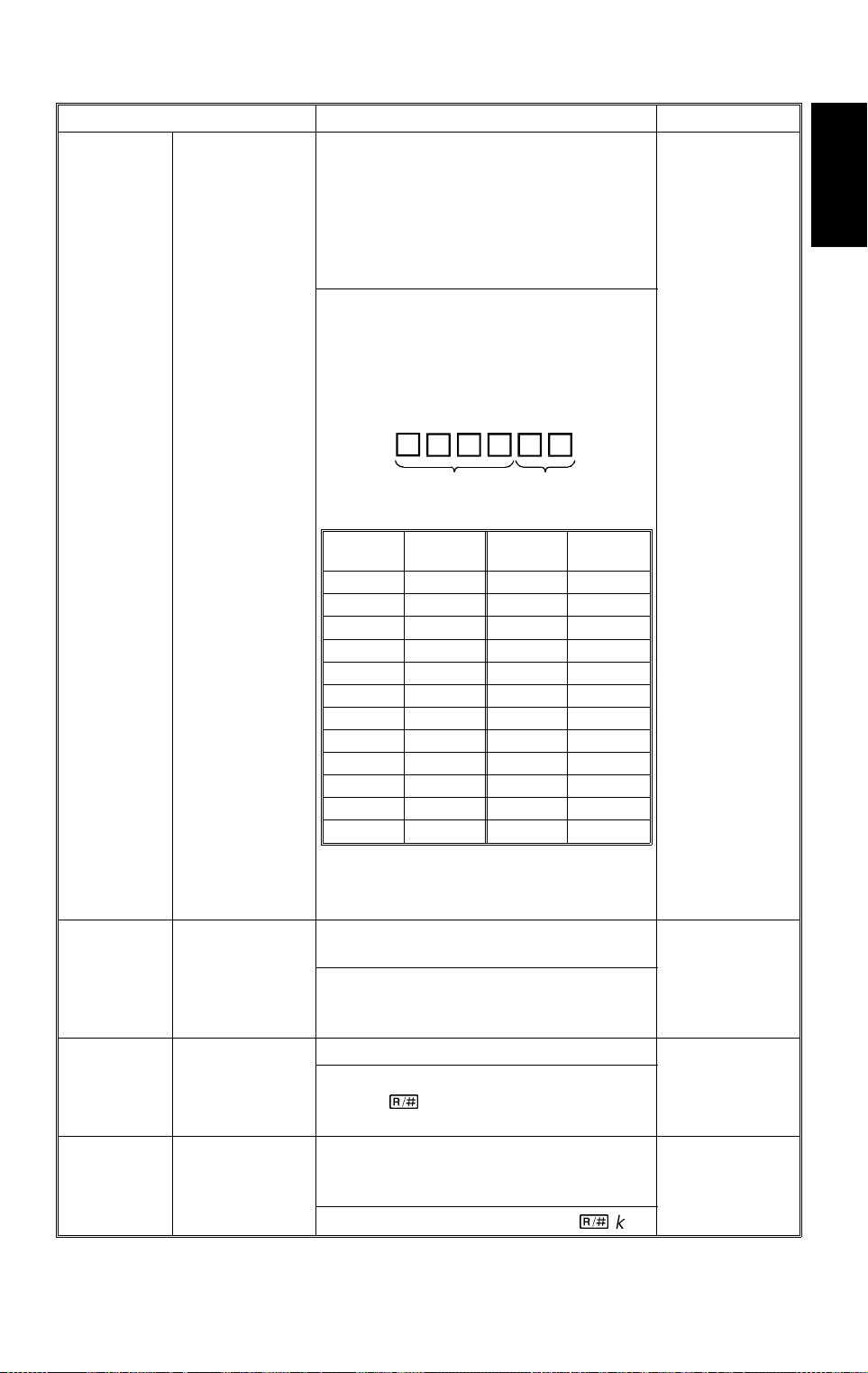
31 March 1997 SERVICE PROGRAM MODE
Mode No. Function Settings
Main ROM
Version Display
†
Displays the main ROM version.
SP7-801-001: Copier m ai n R O M ver si on
SP7-801-002: Paper tray unit main
ROM version
SP7-801-003: DF main ROM version
SP7-801-004: Sorter staple r mai n ROM
version
The ROM versi on i s di splayed by a sixdigit number . Th e fir st three digits are
displayed in th e reduce/enlarge indicator.
Hold down the "
" key to display the last
•
three digits. The six-digit number shows
the ROM version as follows.
°7-801-001
Last four digits
of ROM P/No.
Suffix of ROM
P/No.
to
7-801-004
Last two
digits
00 No suf fix 13 M
01 A 14 N
02 B 16 P
03 C 17 Q
04 D 18 R
05 E 19 S
06 F 20 T
07 G 22 V
08 H 23 W
10 J 24 X
11 K 25 Y
12L26Z
Suffix
Last two
digits
Suffix
Copier
°7-803
°7-804
°7-807-001
PM Counter
Check †
PM Counter
Clear
SC Counter
Clear †
Note:
09, 15, 21 do not exi st because
suffixes I, O, and U are not used.
Displays the PM counter after the l ast
PM (max. 6 digits).
The first three d i gi t s ar e di splayed in the
reduce/enla rg e i ndi cator; hold down the
"
" key to display the last three digits.
•
Resets the PM counter.
The counter will be reset when you press
the final
%
key when entering this SP
mode.
Resets the total SC counter (SP7-401)
and the individual counters for e ach type
of Service Call (SP7-402).
To reset the counter s, press the % key.
87
Page 91

SERVICE PROGRAM MODE 31 March 1997
Mode No. Function Settings
°7-807-002
Copy Jam
Counter Reset
†
(displayed as
Resets the total copy jam counter
(SP7-502) and the copy jam counters for
individual locat i ons (SP7-504).
To reset the counter s, press the % key.
"SC Counter
Clear")
°7-807-003
°7-808
Original Jam
Counter Reset
†
(displayed as
"SC Counter
Clear")
Counter All
Clear
Resets the total original jam counter
(SP7-503) and the original jam counters
for individual l ocations (SP7-505).
To reset the counter s, press the % key.
Resets the following counters.
Counters that are reset Counter check
Operation Time SP7-001
Scanning Counter SP7-002
Copy Counter SP7-101
Total Sheets of Paper Fed from
the Paper Tray
DF Originals Counter SP7-205
Stapler Counter SP7-206
Reduction/Enlargement Counter SP7-301
Total Service Call Counter SP7-401
Each Service Call Counter SP7-402
Jam Total Counter SP7-501
Copy Paper Jam Tot al Counter SP7-502
Original Jam Total Counter SP7-503
Total Coun t e r of Co py Pa pe r
Jams for Each location
Total Count er of Origin al Paper
Jams for Each location
PM Counter SP7-803
SP7-204
SP7-504
SP7-505
°7-810
°7-811
Copy Counter
Clear
DF Counter
Clear
After pressing the f i nal % key when
entering this SP mode, the counters will
be reset.
Resets the following counters.
Total Original C ounter (SP7-002)
•
Total Copies by Paper Size (SP7-101)
•
Total Copies by Magnification
•
(SP7-301)
After pressing the f i nal % key when
entering this SP mode, the counters will
be reset.
Resets the DF counter (SP7-205).
After pressing the f i nal % key when
entering this SP mode, the counter will
be reset.
88
Page 92

31 March 1997 SERVICE PROGRAM MODE
Mode No. Function Settings
Feed Unit
Counter Clear †
°7-816-001
to
7-816-008
Reset one of the foll owing counters by
pressing the % key.
SP Number Without Duplex With Duplex
SP7-816-001 1st tray —
SP7-816-002 2nd tray 1st tray
SP7-816-003 3rd tray 2nd tray
SP7-816- 004 4th tray 3r d t r ay
SP7-816-005 5th tray 4th tray
SP7-816-006 LCT LCT
SP7-816-007 By-pass By-pass
SP7-816-008 — Duplex
Copier
89
Page 93

SERVICE PROGRAM MODE 31 March 1997
12.2 UP MODE AND SP MODE CROSS REFERENCE TABLE
UP Mode SP Mode Function
1 5-019 Paper Size Set
2 5-002 Feed Station Priority Selection
3 5-003 APS Priority Selection
4 6-010 Auto APS Select (DF)
5 5-103 Auto Tray Shift
6 5-013 Counter Up/Down Selection
7 5-017 Maximum Copy Quantity
8 5-101 Auto Reset Time Setting
9 5-102 Auto Energy Saver Time Setting
10 5-305-001 Auto Off Time Setting
11 5-004 ADS Priority Selection
12 5-106 Image Density Level Correction
13 5-907 Cover Mode Selection
14 5-908 Image Shift/Erase Selection
15 5-909 10 Key Zoom/Size Magnification
16 5-107 Image Shift Margin Adjustment
17 5-108 Edge Erase Margin Adjustmen t
18 5-110 Center Erase Margin Adjustment
19 5-906 Manual Staple Reset Time Setti ng
20 6-001 SADF Auto Reset Time Setting
21 6-002 Not used
22 6-011 Thick/Thin Original Mode Selectio n
23 5-402 User Code Counter Check
24 5-404 User Code Counter Clea r
25 5-405 User Code Number Setting
26 5-407 User Code Number Clear
27 5-001 All Indicators On
28 4-902 Not used
29 5-122 OHP Slip Sheet Mode Selection
30 5-910 Guidance Language Set
31 5-410 User Code Reset Time Setting
32 5-021 Duplex Priority Selection (Energy Star)
90
Page 94

31 March 1997 PREVENTIVE MAINTENANCE SCHEDULE
13. PREVENTIVE MAINTENANCE SCHEDULE
13.1 PM TABLE
NOTE:
OPTICS
Mirrors, Lens, Reflector
Exposure Glass C C C C Alco hol or gl ass cleaner
Exposure Lamp I C/I C/I C/I Replace if necessary
Green Filter C C C Dry cloth
Scanner Guide R ai l s C C C Dry cl ot h
ADS, APS sensors
Lens Block Guide Rail C C C C Dry cloth
Dust Filter C C C Replace if necessary
NOTE:
The toner shield glass ha s been elimina te d. ✽
The amounts mentioned as the PM interval indicate the number of
copies.
Symbol key: C: Clean R: Replace L: Lubricate I: Inspect
A204/A206/A207 EM 120 k 240 k 360 k NOTE
CCC
CCC
After cleaning th e exposure lam p and/or optics, do SP4-001, then 4-201, th en 3-105.
Cotton pad with wa ter, or blower
brush.
Blower brush. Do SP4 -2 01 af t er
cleaning the ADS sensor.
Copier
AROUND THE DRUM
Drum Charge Roller
Drum Charge Roller
Cleaner
Drum Charge Roller
Terminal
ID Sensor
Erase Lamp C C C Dry clot h
Quenching La m p C C C Dry clot h
Pick-off Pawls C R C Dry cloth
Pre-Transfer L am p C C C Dry cloth and blower brush
DEVELOPMENT UNIT
Developer R R R Do SP2-214 after replacement .
Side Seal I I I
Development Filter R R R
Entrance Seal C C C C Replace if necessary
Toner Supply Unit C C C C Blowe r brush
RRR
RRR
RRR
CCC
Clean with the special cloth if
necessary (th e cl ot h m ust be dry)
Replace with t he dr um charge roller
as a set.
Replace with t he dr um charge roller
as a set.
Blower brush. After cleaning, do
SP3-001 then SP3-112.
91
Page 95

PREVENTIVE MAINTENANCE SCHEDULE 31 March 1997
A204/A206/A207 EM 120 k 240 k 360 k NOTE
PAPER FEED (for each paper feed station)
Pick-up, Feed,
Separation Rollers
(Paper tray)
Pick-up, Feed,
Separation Rollers
(LCT,By-pass fe ed)
Separation Torque
Limiter (By-pass feed)
(A204 only)
Paper Feed Guide Plate C C C Alcohol
Relay rollers C C C Alcohol or water
Registrati on r ol l er C C C Alcohol or wate r
Bottom Plate Pad
(Paper tray, By- pass
feed, LCT)
CLEANING UNIT
Drum Cleaning Blade
Side Seal C C C Replace if necessary
Cleaning Ent ra n ce Seal C C C Replace if necessary
CCRC
CCRC
R
CRRR
RRR
Clean with water. Replace these
rollers as a set.
Clean with water. Replace these
rollers as a set.
Clean with water. Replace with the
rollers as a set.
Water
Spread setting powder. See "Drum
Cleani ng Blade Re placement".
TRANSFER BELT UNIT
Transfer Belt C C R C Sprea d set t i ng powder. "See Tran sf er
Transfer Belt Cleaning
Blade
Used Toner Tan k C C C Blower brush or vacuum cleaner
FUSING UNIT
Fusing Entrance and
Exit Guide Plates
Fusing Lamps I I I Replace if necessary
Hot Roller
Pressure Roller ✽ RRR
Fusing Thermistors C I I I Suitable solvent
Hot and Pressure
Roller Bearings
Fusing Antist atic Brush I I I Replace if necessary
Cleaning Roller R R R Suitable solvent
Cleaning Roller
Bushings
Oil Supply Roller ✽ RRR
RRR
CCC
RRR
III
III
Belt Cleaning Blad e R epl acement"
Suitable solvent
Grease Barrierta JFE 55/2 on the
✽
flange
Replace if nec essary
Replace if nec essary
92
Page 96

31 March 1997 PREVENTIVE MAINTENANCE SCHEDULE
A204/A206/A207 EM 120 k 240 k 360 k NOTE
Oil Supply Roller
Cleaning Brush ✽
Fusing Exit Rollers C
Turn Guide Transport
Rollers
Hot Roller Strippers C R R R
Oil Supply Roller
Bushing ✽ (One-way)
DUPLEX TRAY
Clutch Spring L L L Mobil Temp 78. See Note 1.
Feed Roller R R R
Bottom Plate Pad R R R
Mylars I I I Replace if necessary
OTHERS
Drive Belts I I I Replace if necessary
RRR
C
III
Replace if nec essary
Copier
A208/A210/A211 EM 120 k 240 k 360 k NOTE
OPTICS
Mirrors, Lens, Reflector
Exposure Glass C C C C Alco hol or gl ass cleaner
Exposure Lamp I I I I Replace if necessary
Green Filter C C C Dry cloth
Scanner Guide R ai l s C C C Dry cl ot h
ADS, APS sensors
Lens Block Guide Rail C C C C Dry cloth
Dust Filter C C C Replace if necessary
NOTE:
The toner shield glass ha s been elimina te d. ✽
AROUND THE DRUM
Drum Charge Roller
Drum Charge Roller
Cleaner
Drum Charge Roller
Terminal
ID Sensor
After cleaning th e exposure lam p and/or optics, do SP4-001, then 4-201, th en 3-105.
CCC
CCC
RRR
RRR
RRR
CCC
Cotton pad with wa ter, or blower
brush
Blower brush. Do SP4 -2 01 af t er
cleaning the ADS sensor.
Clean with the special cloth if
necessary (th e cl ot h m ust be dry)
Replace with t he dr um charge roller
as a set.
Replace with t he dr um charge roller
as a set.
Blower brush. After cleaning, do
SP3-001 then SP3-112.
93
Page 97

PREVENTIVE MAINTENANCE SCHEDULE 31 March 1997
A208/A210/A211 EM 120 k 240 k 360 k NOTE
Erase Lamp C C C Dry clot h
Quenching La m p C C C Dry clot h
Pick-off Pawls C R C Dry cloth
Pre-Transfer L am p C C C Dry cloth and blower brush
DEVELOPMENT UNIT
Developer R R R Do SP2-214 after replacement .
Side Seal I I I
Development Filter R R R
Entrance Seal C C C C Replace if necessary
Toner Supply Unit C C C C Blowe r brush
PAPER FEED (for each paper feed station)
Pick-up, Feed,
Separation Rollers
(Paper tray) ✽
Pick-up, Feed,
Separation Rollers
(LCT, By-pass feed)
Separation Torque
Limiter (By-pass feed)
(A208 only)
Paper Feed Guide Plate C C C Alcohol or water
Relay rollers C C C Alcohol or water
Registrati on r ol l er C C C Alcohol or wate r
Bottom Plate Pad
(Paper tray, By- pass
feed, LCT)
CCRC
CCRC
R
CRRR
Water
Clean with water. Replace these
rollers and th e to rque limiter as a set .
Clean with water. Replace these
rollers and th e to rque limiter as a set .
Water
CLEANING UNIT
Drum Cleaning Blade
Side Seal C C C Replace if necessary
Cleaning Ent ra n ce Seal C C C Replace if necessary
TRANSFER BELT UNIT
Transfer Belt C C R C Sprea d set t i ng powder. "See Tran sf er
Transfer Belt Cleaning
Blade
Used Toner Tan k C C C Blower brush or vacuum cleaner
FUSING UNIT
Fusing Entrance and
Exit Guide Plates
CRRR
RRR
CCC
94
Spread setting powder. See "Drum
Cleani ng Blade Re placement".
Belt Cleaning Blad e R epl acement"
Wipe with a dry clot h.
Suitable solvent
Page 98

31 March 1997 PREVENTIVE MAINTENANCE SCHEDULE
A208/A210/A211 EM 120 k 240 k 360 k NOTE
Fusing Lamps I I I Replace if necessary
Hot Roller R R R
Pressure Roller C R C Suitable solvent
Fusing Thermistors C I I I Suitable solvent
Hot and Pressure
Roller Bearings
Fusing Antist atic Brush I I I Replace if necessary
Cleaning Roller R R R Suitable solvent
Cleaning Roller
Bushings
Fusing Exit Rollers C
Turn Guide Transport
Rollers
Hot Roller Strippers C R R R
DUPLEX TRAY
Clutch Spring L L L Mobil Temp 78. See Note 1.
Feed Roller R R R
Bottom Plate Pad R R R
Mylars I I I Replace if necessary
III
III
C
Replace if nec essary
Replace if nec essary
Copier
OTHERS
Drive Belts I I I Replace if necessary
EM 120 k 240 k 360 k NOTE
SORTER ADAPTER (A568)
Exit Drive Roller C Alcohol or Water
Upper Roller C Alcohol or Water
EM 120 k 240 k 360 k NOTE
PAPER TRAY UNIT (A549/A550)
Pick-up, Feed,
Separation Rollers
Relay rollers C C C Alcohol or water
Bottom Plate Pad C R R R Water
Relay Clutch I I I Replace every 1, 500 k copies.
Feed Clutch I I I Replace if necessary
Drive Belts I I I Replace if necessary
CCRC
Water, Replace these rollers as a set.
95
Page 99

PREVENTIVE MAINTENANCE SCHEDULE 31 March 1997
EM 80 k 160 k 240 k NOTE
AUTO DOCUMENT FEEDER (A663) (for originals)
Transport Belt C R R R Belt cleaner
Friction Belt C R R R Water
Separation Roller C R R R Water
EM PM NOTE
20-BIN SORTER STAPLER (A664)
Transport and Exit Rollers C C Alcohol or water
Bins C C Alcohol or water
Bin and Paper Sensors C C Alcohol or water
Bushings L L Launa oil; if bushin gs generate noise
Worm Gears L L Grease G501; if worm gears generate noi se
Stapler Replace after 200 k staple.
Exit Mylars Replace after 1,000 k copies.
20-BIN SORTER STAPLER (A658)
Transport and Exit Rollers C C Alcohol or water
Bins C C Alcohol or water
Bin and Paper Sensors C C Blower brush
Bushings L L Launa oil; if bushin gs generate noise.
Helicam Wheels L L Grease G501; if worm gears generate noi se.
Bin Cam Tr acks
10-BIN SORTER STAPLER (A555)
Transport Roller C C Alcohol or water
Bins C C Alcohol or water
Bin and Paper Sensors C C Blower brush
Bushings L L Launa oil; if bushin gs generate noise.
Helicam Wheels
SORTER (A556/A557)
Bin Guide/W heel L L Grease G5 01; i f those generate noise.
Bushings L L Grease G501; if bushi ngs generate no i se.
Exit Roller C C Alcohol or water
LL
LL
Grease G501; i f bin cam tracks generate
noise.
Grease G501; i f he l i cam w heels generate
noise.
96
Page 100

31 March 1997 PREVENTIVE MAINTENANCE SCHEDULE
13.2 REGULAR PM PROCEDURE
1. Make a Copy
2. Optics (every 120 k)
Every 120 k (A204/A206/A207),
or 100 k (A208/A210/A211)
Copier
Every 240 k (A204/A206/A207),
or 200 k (A208/A210/A211)
Make a copy of an OS-A3 test chart at manual
image density level 4.
1. Clean the mirrors, lens, and reflectors with a
soft cloth, cotton pad with water, or a blower
brush.
2. Clean the exposure glass with alcohol or glass
cleaner.
3. Clean the scanner guide rail with a dry cloth.
4. Clean the lens block guide rail with a dry cloth.
5. Clean the ADS sensor and the original width
and length sensors
3. Around the Drum
(every 120 k)
Replace the
pick-off pawls
(every 240 k).
6. Inspect the exposure lamp.
7. Clean the dust filter.
1. Remove the drum and clean the ID sensor
with a blower brush.
2. Clean the pick-off pawls.
3. Clean the quenching, erase, and pre-transfer
lamps with a dry cloth. Discharge any static
electricity before putting them back.
4. Put back the drum.
5. Replace the drum charge roller, drum charge
roller cleaner, and drum charge roller terminal
and roller terminal.
97
 Loading...