

Page 1

SECTION 1
OVERALL MACHINE INFORMATION
Page 2

13th January 1995 SPECIFICATIONS
1. SPECIFICATIONS
Configuration: Desktop
Copy Process: Dry electrostatic transfer system
Originals: Sheet/Book
Original Size: Maximum A3/11" x 17"
Copy Paper Size: Maximum
A3/11" x17" (Paper trays)
Minimum
A5/81/2" x 51/2" sideways (Paper trays)
A4/11" x 81/2" sideways (LCT)
A6/51/2" x 81/2" lengthwise (By-pass)
Duplex Copying: Maximum
A3/11" x 17"
Minimum
A5/81/2" x 51/2" (sideways)
Copy Paper Weight: Paper tray:
52 ~ 128 g/m2, 14 ~34 lb
(A153, A155, and A156 copiers)
64 ~ 90 g/m2, 17 ~ 24 lb
(A157, A159, and A160 copiers)
By-pass:
52 ~ 157 g/m2, 14 ~42 lb
LCT:
52 ~ 128 g/m2, 14 ~ 34 lb
Duplex copying:
64 ~ 105 g/m2, 17 ~ 24 lb
Overall
Information
Reproduction Ratios: 4 Enlargement and 6 Red uction
A4/A3 Version LT/DLT Version
200%
Enlargement
Full size 100% 100%
Reduction
1-1
141%
122%
115%
93%
82%
75%
71%
65%
50%
200%
155%
129%
121%
93%
85%
77%
74%
65%
50%
Page 3

SPECIFICATIONS 13th January 1995
Power Source: 120V/60Hz:
More than 12 A (for North America)
220V ~ 240V/50Hz:
More than 7 A (for Europe)
220V/50Hz:
More than 7 A (for Asia)
110V/60Hz:
More than 14 A (for Taiwan)
220V/60Hz:
More than 7 A (for Saudi Arabia, Philippines)
Power Consumption:
A153, A155, and A156 copiers A157, A159, and A160 copiers
Copier Only Full System Copier Only Full System
Maximum 1.45 KW 1.50 KW 1.45 KW 1.50 KW
Copying 1.00 KW 1.00 KW 0.80 KW 0.80 KW
Warm-up 0.90 KW 0.92 KW 0.90 KW 0.92 KW
Stand-by 0.16 KW 0.19 KW 0.15 KW 0.17 KW
1 0.15 KW 0.17 KW 0.14 KW 0.16 KW
Energy
Saver
Auto Off 0.02 KW 0.04 KW 0.02 KW 0.04 KW
2 0.13 KW 0.15 KW 0.12 KW 0.13 KW
3 0.12 KW 0.14 KW 0.09 KW 0.10 KW
4 0.11 KW 0.12 KW 0.07 KW 0.08 KW
5 0.09 KW 0.11 KW 0.05 KW 0.06 KW
6 0.07 KW 0.09 KW – –
NOTE: 1) Full System: Copier + ADF + Paper Tray Unit + 20 Bin S/S
2) Energy Saver: Se e SP 1-105-002
3) Auto Off: See SP5-305
Noise Emission:
A153, A155, and A156 copiers A157, A159, and A160 copiers
Copier Only Full System* Copier Only Full System*
1. Sound Power Level
Copying 66 dB(A) 68 dB(A) 61 dB(A) 67 dB(A) (L
Warm-up 41 dB(A) 41 dB(A) 39 dB(A) 40 dB(A) (L
Stand-by 41 dB(A) 41 dB(A) 39 dB(A) 40 dB(A) (L
2. Sound Pressure Level at the operator position
Copying 58 dB(A) 57 dB(A) 54 dB(A) 56 dB(A) (L
Warm-up 33 dB(A) 27 dB(A) 32 dB(A) 27 dB(A) (L
Stand-by 33 dB(A) 27 dB(A) 32 dB(A) 27 dB(A) (L
NOTE: The above measurements are to be made according to ISO 77 79 .
* : Full System: Copier + ADF + Paper Tray Unit +10 Bin S/S .
WA)
WA)
WA)
PA)
PA)
PA)
1-2
Page 4

13th January 1995 SPECIFICATIONS
Dimensions:
Width Depth Height
A153 copier 1030 mm (40.6") 655 mm (25.8") 606 mm (23.9")
A157 copier 900 mm (35.5") 655 mm (25.8") 606 mm (23.9")
A155 and A156
copiers
A159 and A160
copiers
1258 mm (49.6") 655 mm (25.8") 606 mm (23.9")
1128 mm (44.5") 655 mm (25.8") 606 mm (23.9")
Measurement Conditions
1) With by-pass feed table closed
2) With platen cover and copy tray attached
3) With LCT cover closed
Weight:
Weight
A153 copier About 70 kg (154.2 lb)
A155 copier About 78 kg (171.9 lb)
A156 copier About 82 kg (180.7 lb)
A157 copier About 67 kg (147.7 lb)
A159 copier About 75 kg (165.4 lb)
A160 copier About 80 kg (176.4 lb)
Overall
Information
Zoom: From 50% to 200% in 1% steps
Copying Speed (copies/minute):
A153, A155, and
A156 copiers
A157, A159, and
A160 copiers
A4 sideways/
11" x 8
1/2"
35 20/19 22
27 15/14 17
A3/11" x 17" B4/8
Warm-Up Time A153, A155, and A156 copiers:
Less than 110 second s (2 0 ° C)
A157, A159, and A160 copiers:
Less than 80 seconds (20°C)
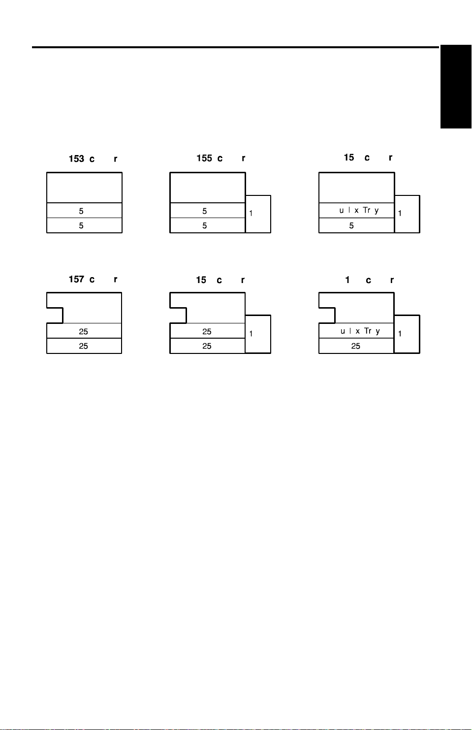
First Copy Time:
Paper Feed Station
1st Tray 5.2 s (except for A156) 5.9 s (except for A160)
2nd Tray 5.7 s 6.6 s
By-pass 4.8 s 5.6 s
LCT 5.0 s 5.9 s
A153, A155, and A156 copiers A157, A159, and A160 copiers
A4/11" x 8
1/2" (sideways)
1/2" x 14"
Note: In A156 and A160 copiers, the 2nd tray in th e above tab le is called the
1st tray (see Installation - Paper Feed St at ion Definition).
1-3
Page 5

SPECIFICATIONS 13th January 1995
Copy Number Input: Ten-key pad, 1 to 999 (count up or count down)
Manual Image Density
7 steps
Selection:
Automatic Reset: 1 minute is the standard set ting; it can be
changed to a maximum of 999 seconds or no
auto reset by SP mode.
Copy Paper Capacity:
Paper Tray By-pass Feed LCT
A153 copier About 500 sheets x2 About 40 sheets –
A155 copier About 500 sheets x2 About 40 sheets About 1000 sheets
A156 copier About 500 sheets x1 About 40 sheets About 1000 sheets
A157 copier About 250 sheets x2 About 40 sheets –
A159 copier About 250 sheets x2 About 40 sheets About 1000 sheets
A160 copier About 250 sheets x1 About 40 sheets About 1000 sheets
Duplex Tray Capacity
[A156/A160]:
50 sheets (30 sheets for A3/11"x17"
81 ~ 105g/m2, 21.5 ~ 27.9 lb paper)
Toner Replenishment: Cartridge exchange (415 g/cartridge)
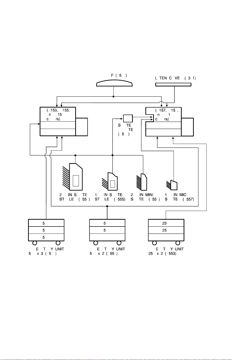
Optional Equipment: • Platen cover
• Document feeder
• Paper tray unit with two paper trays
• Paper tray unit with three paper trays
• 10 bin micro sorter
• 20 bin mini sorter
• 10 bin sorter stapler
• 20 bin sorter stapler
• Sorter adapter (required when installing 20
bin mini sorter, 10 bin sorter stapler, or 20
bin sorter stapler for A1 57, A1 59 , an d A1 60
copiers)
• Key counter
• Tray heater
• Optical anti-condensation heater
• Original length sensor for 11 " x 15" size
paper (only for LT/DLT version)
• ADS sensor for particular types of red orig ina l
1-4
Page 6
13th January 1995 MACHINE CONFIGURATION
2. MACHINE CONFIGURATION
2.1 COPIER
Overall
Information
1-5
Page 7
MACHINE CONFIGURATION 13th January 1995
2.2 OPTIONAL EQUIPMENT
1-6
Page 8
29
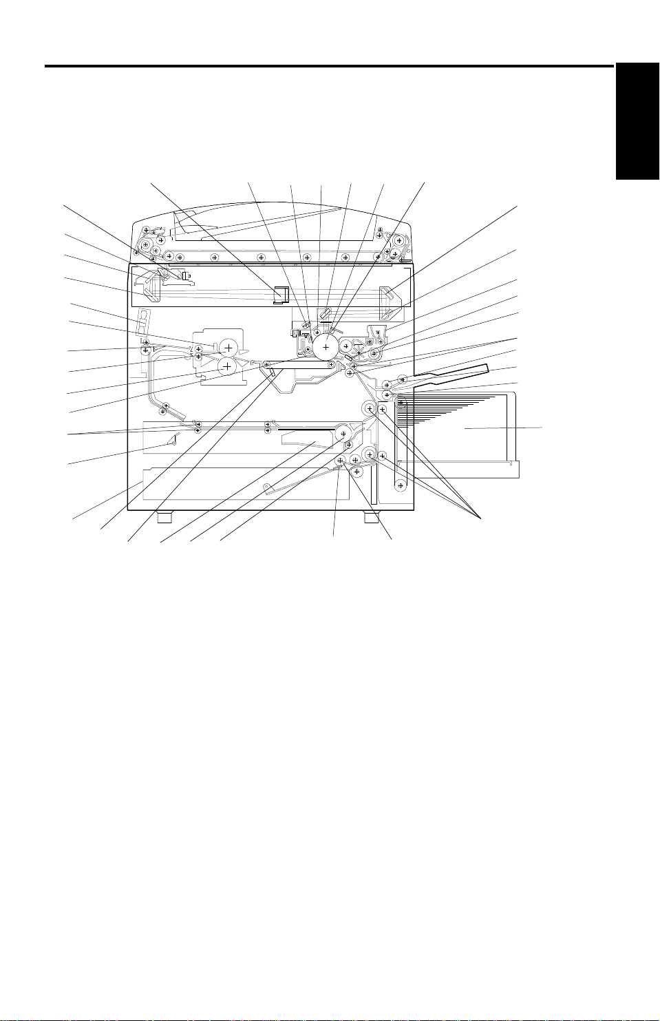
13th January 1995 MECHANICAL COMPONENT LAYOUT
3. MECHANICAL COMPONENT LAYOUT
– A156 copier –
5
6
7
1098
11
Overall
Information
4
3
2
1
38
37
36
35
34
33
32
31
30
28
27
26
25
12
13
14
15
16
17
18
19
20
21
22
24 23
NOTE: 1. The A153 copier is the same as the A15 6 cop ier exce pt that the
A153 does not have a duplex tray or an LCT.
2. The A155 copier is the same as the A15 6 cop ier exce pt that the
A155 does not have a duplex tray.
1-7
Page 9
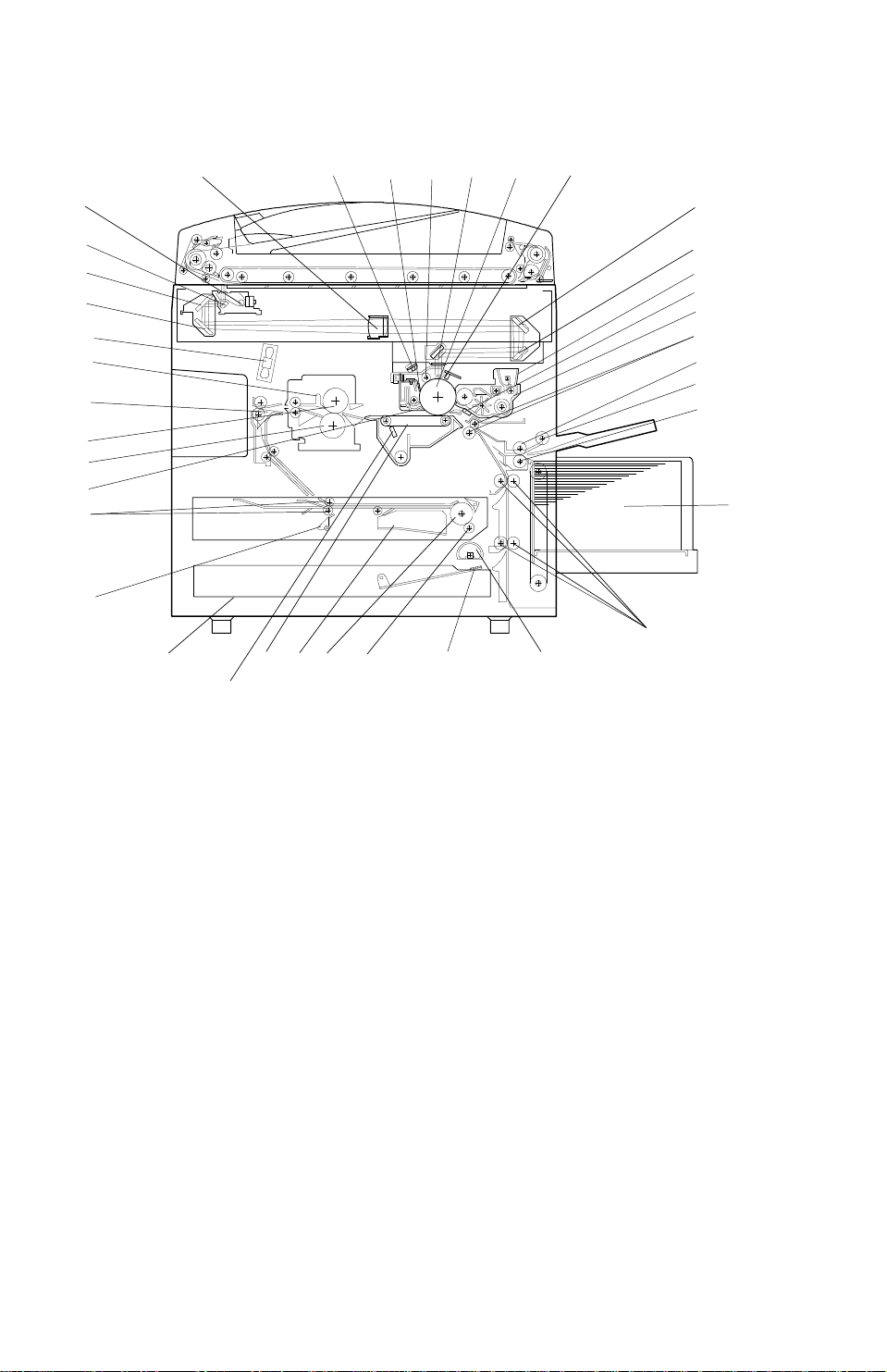
MECHANICAL COMPONENT LAYOUT 13th January 1995
– A160 copier –
4
3
2
1
38
37
36
35
34
33
32
31
30
5
6
7
1098
11
12
13
14
15
16
17
18
19
20
21
22
28
27
26
25
24
23
29
NOTE: 1. The A157 copier is the same as the A16 0 cop ier exce pt that the
A157 does not have a duplex tray or an LCT.
2. The A159 copier is the same as the A16 0 cop ier exce pt that the
A159 does not have a duplex tray.
1-8
Page 10

13th January 1995 MECHANICAL COMPONENT LAYOUT
1. 3rd Mirror
22. Vertical Transport Rollers
2. 2nd Mirror
3. 1st Mirror
4. Exposure Lamp
5. Lens
6. Quenching Lamp
7. Drum Cleaning Blade
8. Drum Charge Roller
9. 6th Mirror
10. OPC Drum
11. Erase Lamp
12. 4th Mirror
13. 5th Mirror
14. Toner Supply Unit
23. Paper Feed Roller
The roller for A153/A155/A156
copiers is different from that
for A157/159/160 copiers.
24. Friction Pad
25. Duplex Friction Roller
26. Duplex Feed Roller
27. Jogger Fence
28. Transfer Belt
29. Transfer Belt Cleaning Blade
30. Lower Paper Tray
31. End Fence
32. Entrance Rollers
33. Pick-off Pawls
Overall
Information
15. Pre-transfer Lamp
16. Development Unit
17. Registration Rollers
18. Feed Roller
19. Pick-up Roller
20. Separation Roller
21. Large Capacity Tray
34. Pressure Roller
35. Hot Roller
36. Junction Gate
37. Hot Roller Strippers
38. Transport Fan
1-9
Page 11
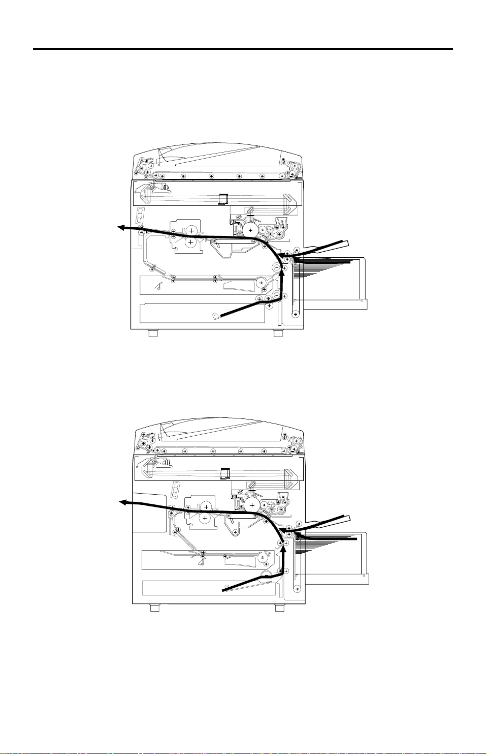
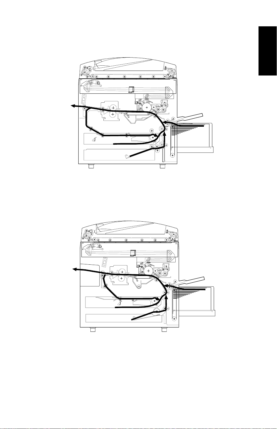
PAPER PATH 13th January 1995
4. PAPER PATH
4.1 NORMAL COPYING
– A156 copier –
–A160 copier –
1-10
Page 12
13th January 1995 PAPER PATH
4.2 DUPLEX COPYING
– A156 copier –
Overall
Information
– A160 copier –
1-11
Page 13

ELECTRICAL COMPONENT DESCRIPTIONS 13th January 1995
5. ELECTRICAL COMPONENT DESCRIPTIONS
Refer to the electrical compone nt layou t an d the po int to point diag ram on the
waterproof paper in th e pocket for symbols and index numbers.
Symbol
Printed Circuit Boards
PCB1 14
PCB2 12
PCB3 11 DC Power Supply Provides dc power.
PCB4 96 Main Motor Control Controls the rotation of the main motor.
PCB5 1
PCB6 55 T High Voltage Supply Supplies high voltage to the transfer belt.
PCB7 3
PCB8 8
PCB9 63
PCB10 6
PCB11 102
Motors
M1 88 Main Drives the main unit components.
M2 79
M3 97
M4 86
M5 99
M6 94 Optics Cooling Fan 1 Removes heat from the optics unit.
M7 95
M8 89
M9 90
Index
No.
Description Note
Main Control Controls all copier functions both directly or
through other control boards.
AC Drive Provides ac power to the exposure lamp and
fusing lamps.
CB High Voltage
Supply
Operation Panel Controls the LED matrix, and monitors the
Noise Filter (220 ~
240 V machines only)
Duplex Control
(Duplex machines
only)
Liquid Crystal Display
(A156 machines only)
LCT Interface
(LCT machines only)
Toner Bottle Drive Rotates the toner bottle to supply toner to
Upper Tray Lift
(A153/A155
machines only)
Lower Tray Lift
(A153/A155/A156
machines only)
LCT Lift
(LCT machines only)
Optics Cooling Fan 2
(A153/A155/A156
machines only)
Exhaust Fan 1 Removes the heat from around the fusing
Exhaust Fan 2
(A153/A155/A156
machines only)
Supplies high voltage to the drum charge
roller and development roller.
key matrix.
Removes electrical noise.
Controls the operation of the duplex tray.
Controls the guidance display and displays
guidance for machine operation.
Interfaces the LCT control signal between
the main board and the LCT.
the toner supply unit.
Raises the bottom plate in the upper paper
tray.
Raises the bottom plate in the lower paper
tray.
Lifts up and lowers the LCT bottom plate.
Removes heat from the optics unit.
unit.
Removes the heat from around the fusing
unit.
1-12
Page 14

13th January 1995 ELECTRICAL COMPONENT DESCRIPTIONS
Symbol
M10 92
M11 78 3rd Scanner Drive Drives the 3rd scanner (dc stepper motor).
M12 87 Lens Vertical Drive Shifts the lens vertical position.
M13 77 Lens Horizontal Drive Shifts the lens horizontal position.
M14 58
M15 61
M16 60
Sensors
S1 27
S2 31
S3 51
S4 107
S5 29
S6 52
S7 106
S8 30
S9 100
S10 26
S11 28
Index
No.
Description Note
Scanner Drive Drives the 1st and 2nd scanners (dc stepper
motor).
Duplex Feed
(Duplex machines
only)
End Fence Jogger
(Duplex machines
only)
Side Fence Jogger
(Duplex machines
only)
By-pass Feed Paper
Width
By-pass Feed Paper
End
Upper Tray Paper
End
(Non-duplex
machines only)
Upper Relay Detects the leading edge of paper from the
Upper Tray Upper
Limit
(A153/A155
machines only)
Lower Tray Paper
End
Lower Relay Detects the leading edge of paper from the
Lower Tray Upper
Limit
(A153/A155/A156
machines only)
LCT Lower Limit
(LCT machines only)
LCT Paper End
(LCT machines only)
LCT Upper Limit
(LCT machines only)
Drives the feed roller and moves the bottom
plate up and down.
Drives the end fence jogger to square the
paper stack.
Drives the side fence jogger to square the
paper stack.
Informs the CPU what width paper is in the
by-pass feed table.
Informs the CPU that there is no paper in the
by-pass tray.
Informs the CPU when the upper paper tray
runs out of paper.
upper tray to determine the stop timing of the
upper paper feed clutch, and detects
misfeeds.
Detects the height of the paper stack in the
upper paper tray to stop the upper tray lift
motor.
Informs the CPU when the lower paper tray
runs out of paper.
lower paper tray to determine the stop timing
of the lower paper feed clutch, and detects
misfeeds.
Detects the height of the paper stack in the
lower paper tray to stop the lower tray lift
motor.
Sends a signal to the CPU to stop lowering
the LCT bottom plate.
Informs the CPU when the LCT runs out of
paper.
Sends a signal to the CPU to stop lifting the
LCT bottom plate.
Overall
Information
1-13
Page 15

ELECTRICAL COMPONENT DESCRIPTIONS 13th January 1995
Symbol
S12 28
S13 50
S14 53
S15 39
S16 20
S17 15
S18 24
S19 21
S20 45 Fusing Exit Detects misfeeds.
S21 16
S22 54
S23 43
S24 23
S25 13
S26 44
S27 19
S28 56
S29 57
S30 62
S31 59
S32 64
Index
No.
Description Note
Registration Detects the leading edge of the copy paper
to determine the stop timing of the paper
feed clutch, and detects misfeeds.
Image Density
(ID)
Toner Density
(TD)
Lens Horizontal HP Informs the CPU that the lens is at the
Lens Vertical HP Informs the CPU that the lens is at the
Scanner HP Informs the CPU when the 1st and 2nd
3rd Scanner HP Informs the CPU when the 3rd scanner is at
Original Length-2 Detects the length of the original. This is one
Platen Cover Informs the CPU whether the platen cover is
Toner End Instructs the CPU to add toner to the toner
Auto Response Returns the operation panel display and exits
Transfer Belt ContactHPInforms the CPU of the current position of
Auto Image Density
(ADS Sensor)
Original Width Detects the width of the original. This is one
Original Length-1 Detects the length of the original. This is one
Duplex Paper End
(Duplex machines
only)
Duplex Turn
(Duplex machines
only)
Duplex Entrance
(Duplex machines
only)
Side Fence Jogger
HP (Duplex machines
only)
End Fence Jogger
HP (Duplex machines
only)
Detects the density of various patterns on
the drum during process control.
Detects the amount of toner inside the
development unit.
horizontal home position.
full-size position.
scanners are at the home position.
the home position.
of the APS (Auto Paper Select) sensors.
up or down (related to APS/ARE functions).
ARE: Auto Reduce and Enlarge
supply unit, and detects toner end conditions.
from the energy saver mode.
both the transfer belt unit and the drum
charge roller unit.
Detects the background density of each
original in ADS mode.
of the APS (Auto Paper Select) sensors.
of the APS (Auto Paper Select) sensors.
Detects paper in the duplex tray.
Detects the trailing edge of the copy paper to
determine the jogging timing, and detects
misfeeds.
Detects misfeeds.
Detects the home position of the duplex side
fence jogger.
Detects the home position of the duplex end
fence jogger.
1-14
Page 16

13th January 1995 ELECTRICAL COMPONENT DESCRIPTIONS
Symbol
S33 22
Switches
SW1 33
SW2 36
SW3 35
SW4 104
SW5 25
SW6 34
SW7 32
SW8 105
SW9 103
SW10 42 Main Supplies power to the copier.
SW11 41
SW12 48
Magnetic Clutches
CL1 72
CL2 71 Development Drives the development roller.
CL3 93
CL4 73 Registration Drives the registration rollers.
CL5 74
CL6 76 Relay Drives the relay rollers.
CL7 84
CL8 85
Index
No.
Description Note
Original Length
(Option for N.
American models)
By-pass Feed Table Detects whether the by-pass feed table is
Upper Tray
(Non-duplex
machines only)
Lower Tray Detects whether the lower paper tray is in
Tray Down
(LCT machines only)
Upper Tray Paper
Size
(Non-duplex
machines only)
Lower Tray Paper
Size
Vertical Guide Set
(Non-LCT machines
only)
LCT Cover-1
(LCT machines only)
LCT Cover-2
(LCT machines only)
Front Cover Safety Cuts the ac power line and detects whether
Exit Cover Safety
(A157/A159/A160
machines only)
Toner Supply Turns the toner supply roller to supply toner
Transfer Belt Contact Controls the touch and release movement of
By-pass Feed Starts paper feed from the by-pass feed
Upper Paper Feed
(Non-duplex
machines only)
Lower Paper Feed Starts paper feed from the lower paper tray.
Detects original length for 11" x 15" paper.
open or closed.
Detects whether the upper paper tray is in
place or not.
place or not.
Sends a signal to the CPU to lower the LCT
bottom plate.
Determines what size of paper is in the
upper paper tray.
Determines what size of paper is in the lower
paper tray.
Detects whether the vertical guide is open or
not.
Detects whether the LCT cover is open or
not.
Cuts the dc power line of the LCT lift motor.
the front door is open or not.
Cuts the ac power line and detects whether
the exit cover is open or not.
to the development unit.
both the transfer belt unit and the drum
charge roller unit.
table or LCT.
Starts paper feed from the upper paper tray.
Overall
Information
1-15
Page 17

ELECTRICAL COMPONENT DESCRIPTIONS 13th January 1995
Symbol
Solenoids
SOL1 75
SOL2 91
SOL3 98
SOL4 80
SOL5 82
SOL6 81
SOL7 83
Lamps
L1 17
L2 65
L3 66 Secondary Fusing Provides heat to both ends of the hot roller.
L4 4
Index
No.
Description Note
LCT machines:
LCT/By-Pass Pick-up
Solenoid
Non-LCT machines:
By-pass Pick-up
Solenoid
Junction Gate
(Duplex machines
only)
LCT Pick-up
(LCT machines only)
Upper Tray Pick-up
(A153/A155
machines only)
Lower Tray Pick-up
(A153/A155/A156
machines only)
Upper Tray
Separation
(A153/A155
machines only)
Lower Tray
Separation
(A153/A155/A156
machines only)
Exposure Applies high intensity light to the original for
Main Fusing Provides heat to the central area of the hot
Pre-transfer Reduces the charge remaining on the drum
Picks paper up from the by-pass feed table.
When paper is fed from the LCT, this
solenoid assists SOL3.
Moves the junction gate to direct copies to
the duplex tray or to the paper exit.
Picks up paper from the LCT.
Controls the up/down movement of the
pick-up roller in the upper paper tray.
Controls the up/down movement of the
pick-up roller in the lower paper tray.
Controls the up-down movement of the
separation roller in the upper paper tray feed
station.
Controls the up-down movement of the
separation roller in the lower paper tray feed
station.
exposure.
roller.
surface before transfer.
L5 5
L6 2
Heaters
H1 38
H2 46
Quenching Neutralizes any charge remaining on the
drum surface after cleaning.
Erase After exposure, this eliminates the charge on
areas of the drum that will not be used for
the image.
Drum Turns on when the main switch is off to keep
the temperature around the drum charge
roller at a certain level. Also prevents
moisture from forming around the drum.
Optics
Anti-condensation
(option)
Turns on when the main switch is off to
prevent moisture from forming on the optics.
1-16
Page 18

13th January 1995 ELECTRICAL COMPONENT DESCRIPTIONS
Symbol
H3 37
Thermistors
TH1 69
TH2 70
TH3 47 Optics Monitors the temperature of the optics cavity.
TH4 49
Thermofuses
TF1 68
TF2 67
TF3 18
Counters
CO1 40
CO2 N/A
Others
CB1 9
CC1 10 Choke Coil Removes high frequency current.
TR1 7
Index
No.
Description Note
Lower Tray
(option)
Main Fusing Monitors the temperature at the central area
Secondary Fusing Monitors the temperature at the ends of the
Drum Charge Monitors the temperature of the drum charge
Main Fusing Provides back-up overheat protection in the
Secondary Fusing Provides back-up overheat protection in the
Exposure Lamp Opens the exposure lamp circuit if the 1st
Total Keeps track of the total number of copies
Key
(option)
Circuit Breaker
(220 ~ 240V
machines only)
Transformer
(220 ~ 240V
machines only)
Turns on when the main switch is off to keep
paper dry in the lower paper tray.
of the hot roller.
hot roller.
roller.
fusing unit.
fusing unit.
scanner overheats.
made.
Used for control of authorized use. The
copier will not operate until it is installed.
Provides back-up high current protection for
electrical components.
Steps down the wall voltage to 100 Vac.
Overall
Information
1-17
Page 19
3
4
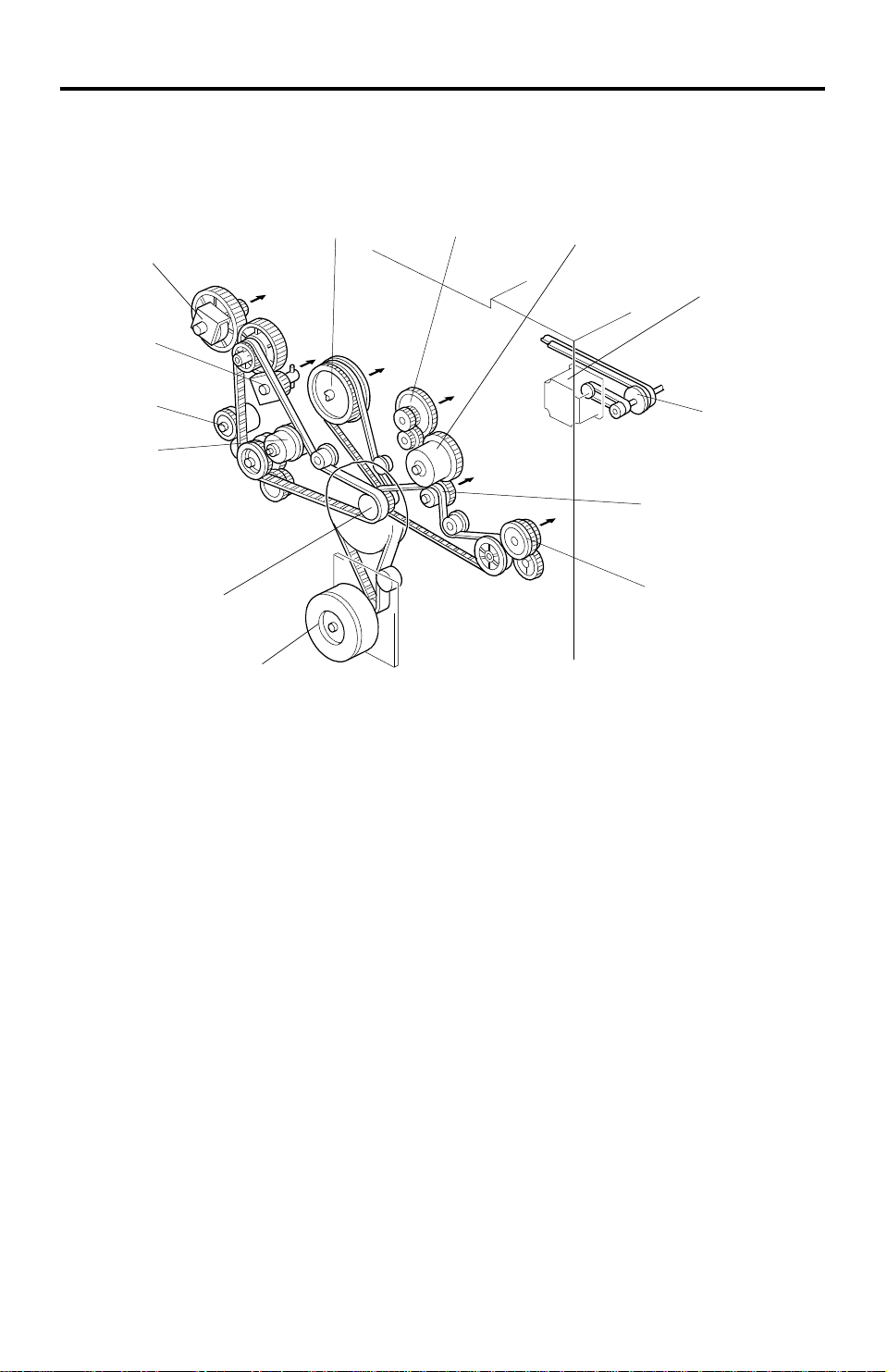
DRIVE LAYOUT 13th January 1995
6. DRIVE LAYOUT
6.1 ALL MODELS
13
12
11
10
1
9
8
2
5
6
7
1 . Drum Drive Pulley
2. Drum Charge Roller Drive Gear
3. Transfer Belt Conta ct Clut ch
Gear
4. Scanner Drive Motor
5. Scanner Drive Pulley
6. Transfer Belt Drive Gear
7. Fusing Unit Drive Gear
8. Main Motor
9. Main Pulley
10. Registration Clutch Gear
11. By-pass Feed Clutch Gear
12. Development Drive Clutch Gear
13. Toner Supply Clutch Gear
1-18
Page 20
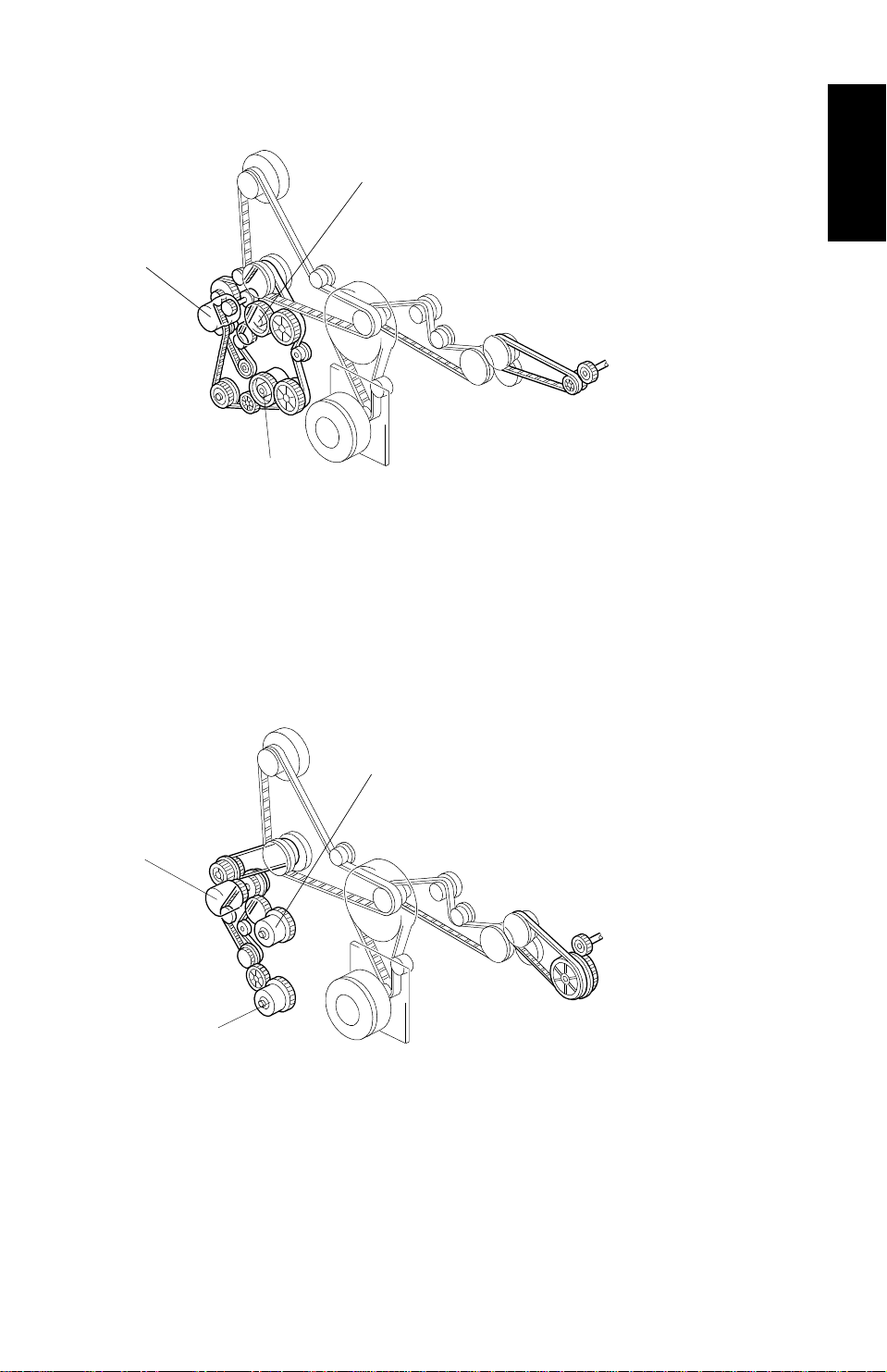
13th January 1995 DRIVE LAYOUT
6.2 A153/A155/A156
1
3
2
1. Upper Paper Feed Clutch Gear (A153/A155 only)
2. Lower Paper Feed Clutch Gear
3. Relay Clutch Gear
6.3 A157/A159/A160
Overall
Information
1
3
2
1. Upper Paper Feed Clutch Gear (A157/A159 only)
2. Lower Paper Feed Clutch Gear
3. Relay Clutch Gear
1-19
Page 21

SECTION 2
DETAILED DESCRIPTIONS
Page 22

13th January 1995 PROCESS CONTROL
1. PROCESS CONTROL
1.1 OVERVIEW
1.1.1 Copy Process around the Drum
2. EXPOSUR E
1. DRUM CHARGE
9. QUENCHING
8. CLEANING
3. ERASE
4. DEVELOPMENT
Detailed
Descriptions
ID
SENSOR
PICK-OFF
PAWLS
TRANSFER BELT
Fig. 1 Copy Process Around the Drum
1. DRUM CHARGE
In the dark, the drum charge roller gives a uniform negative cha rge to the
organic photo-conduct ive (OPC) drum. The charge remains on th e surface of
the drum because the OPC layer has a high electrical resistan ce in the dark.
The amount of negative charge on the dru m is propo rtio na l to th e negative
voltage applied to the drum charg e rolle r.
7. PAPER
SEPARATION
5. PRE-TRANSFER
LAMP
6. IMAGE
TRANSFER
2-1
Page 23

PROCESS CONTROL 13th January 1995
2. EXPOSURE
An image of the original is reflected onto the OPC drum surface via the optics
assembly. The charge on the drum surface is dissipated in direct proportion
to the intensity of the refle cte d light, thus producing an electrical latent image
on the drum surface.
The amount of remaining charg e as a lat ent image on the drum depends on
the exposure lamp intensity, which is co nt rolle d by the exposure lamp voltage.
3. ERASE
The erase lamp illuminates the areas of th e cha rge d dru m su rfa ce th at will
not be used for the copy image. The resistance of the drum in the illuminated
areas drops and the charge on those areas dissipates.
4. DEVELOPMENT
As a result of the development potential (the difference of charged voltage
between the drum and the toner), ton er is att ract ed to the are as of the drum
where the negative charge is greater than that of the toner, and the latent
image is developed.
The development bias volt ag e ap plied to the developmen t rolle r shaft
controls two things:
1) The threshold level fo r wh et he r t on er is attracted to the drum or
whether it remains on the development roller.
2) The amount of toner to be attracted to the drum.
The higher the negative develo pme nt bias volt ag e is, th e less toner is
attracted to the dru m surface.
5. PRE-TRANSFER LAMP (PTL)
The PTL illuminates the drum to remove almost all the negative charge from
the exposed areas of the drum. This prevents the toner particles fro m bein g
reattracted to the drum surf ace during paper separation and makes pa pe r
separation easier.
2-2
Page 24

13th January 1995 PROCESS CONTROL
6. IMAGE TRANSFER
Paper is fed to the area between the drum surf ace and the tran sfer belt at the
proper time so as to align the copy paper and the develope d image on the
drum surface. Then, the tran sfer bias roller applies a strong negative cha rge
to the reverse side of the copy paper through the tran sfer belt. This negative
charge produces an electrical fo rce which pulls the toner particles from t he
drum surface on to the copy paper. At the same time , th e cop y pap er is
electrically attracted to the transfer belt.
7. PAPER SEPARATION
Paper separates from the OPC drum as a result of the electrical attra ction
between the paper and the transfe r belt . The pick-off pawls help separate the
paper from the drum.
8. CLEANING
The cleaning blade remove s ton er rema ining on the drum after the image is
transferred to the pa pe r.
9. QUENCHING
Light from the quenching lamp electrically neutralizes the charge on the dru m
surface.
Detailed
Descriptions
2-3
Page 25
PROCESS CONTROL 13th January 1995
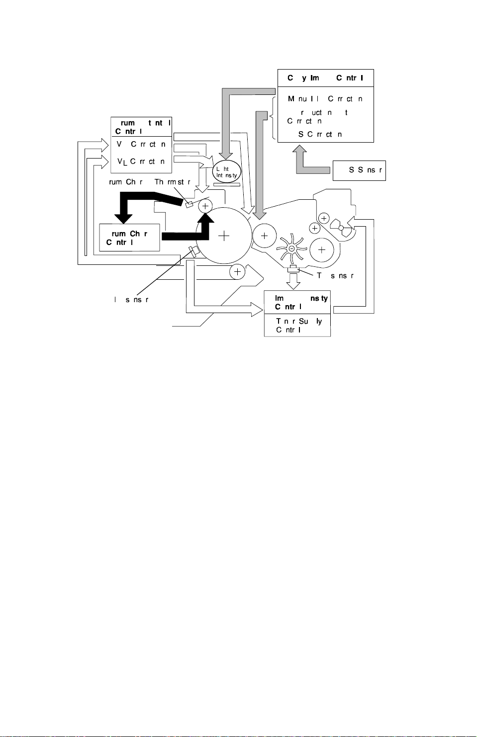
1.1.2 Factors Affecting Process Control
Fig. 2 Process Control
In this copier, the fo llowin g items are controlled durin g th e copy process to
maintain good copy quality:
• Exposure lamp voltage
• Drum charge roller voltage
• Development bias voltage
• Toner supply
The machine controls th e ab ove by monitoring the following electrical
components:
• Operation panel (manual ID selection and reproduction ratio)
• ADS sensor
• TD sensor
• ID sensor
• Drum charge thermistor
• Paper size detecto rs
• RAM board (drum rotatio n time , SP mode data, and paper size da ta)
2-4
Page 26

13th January 1995 PROCESS CONTROL
1.1.3 Process Control Procedures
This section outlines how the machine controls the copy process based on
the inputs from various sensors.
Copy Image Control
This is how the machine adjusts copy processes based on settings input at
the operati on panel.
- Manual ID Correction -
If the user inputs the imag e de nsit y manu ally, the machin e ad just s the
exposure lamp voltage an d the development bias to achie ve th e selected
image density.
- Reproduction Ratio Correction -
If the user selects a 116% or great er en larg ement ratio or a 50% reduction
ratio, the machine corrects the development bia s to comp en sate for the loss
in light intensity reaching the drum.
Detailed
Descriptions
- ADS Pattern Detection and ADS Correction -
If the user selects Auto Ima ge Density (ADS) mode, the machine monitors
the output from the ADS sensor and ad just s the deve lop ment bias to
compensate for variatio ns in ADS sensor response. This preven ts dirty
background.
Every 1,000 copies, the machine calibrates the ADS sensor output by
reading the ADS patt ern und er th e left scale of the exposure glass.
The ADS sensor must also be reca librated:
• If the drum is changed
• If the ID sensor is clean ed or chan ged
• If the exposure lamp or optics are cleaned or cha ng ed .
Image Density Control
This is how the machine corrects th e con centration of toner in the developer
based on readings from the ID (Image Density) and TD (Ton er Den sity)
sensors.
- VSP and VSG Detection/ID Correction -
The machine uses VSP and VSG rea din gs by the ID sensor, along with
readings from the toner density sensor, to determine if the toner
concentration in the deve lop er is at th e optimu m le vel.
2-5
Page 27

PROCESS CONTROL 13th January 1995
The amount of ton er supplied to the VSP pattern must remain constant. To
ensure this, the mach ine app lies a correction to the develop men t bias for V SP
patterns when combine d readings from the TD and ID sensors indicate that
the carrier is ageing. This correction is called "ID Correction".
- Toner Supply -
There are three toner supply modes.
Detect toner supply: Toner supply varies with paper size, the latest TD
sensor reading, and the latest VSP and VSG readings by the ID sensor. For
example, toner supply will be increased if the toner weight rat io in th e
developer is decreasin g, or if the most recent VSP pattern was detected as
being relatively light.
Fixed supply mode: The toner supply remains constant, but can be adjuste d
with an SP mode.
TD supply mode: Toner supply varies with TD sen sor outp ut . For example, if
the toner weight ratio has decreased since TD sensor supply mode was
selected, toner supply is increased.
Drum Potential Control
This is how the machine compensates for aging of the drum an d th e
exposure lamp, and for the temperature around the drum charge roller.
- VR Pattern Detection and VR Correction -
As the drum gets older, the drum’s residual voltage grad ually increases due
to electrical fatigue. Ligh t fro m t he expo sure lamp will not erase the increased
residual voltage effe ctive ly a nd dirty ba ckgro un d will result .
Every 1,000 copies, part of the drum is developed with the VR pattern
development bias. If the re is residu al voltage on the drum, this area of the
drum will attract some toner, making a V R pattern. The ID sensor response to
this pattern is compare d with the response of the ID sensor to a bare area of
the drum. The higher the residu al volt ag e on the drum is, th e da rker th e VR
pattern is. If the pattern is too dark, the drum will not be discharg ed
sufficiently. As a result, the machine will increase the negative de velo pment
bias to prevent dirty background. If it does, image density will drop. To
prevent this, the machine will a lso incre ase the negative drum charge roller
voltage.
(The VRP/VRG range to which the above mentioned bias and charg e
corrections are applied may be shift ed to can cel the ef fe ct of ID correct ion.)
VR correction data must be reset by SP mode if the drum is chan ge d or if th e
ID sensor is cleaned or replaced.
2-6
Page 28

13th January 1995 PROCESS CONTROL
- VL Pattern Detection and VL Correction -
This is how the machine adjusts the expo sure lamp voltage to compensate
for the effects of drum wea r, dirty optics, and response of the drum to lig ht .
Every 1,000 copies, an imag e of the VL pattern under the left scale bracket is
made on the drum. The machine compares the response of the ID sensor to
this image with the response to a bare are a of the drum.
The exposure lamp voltage is adjust ed if there ha ve be en significant changes
from the measurements made from when a new drum or lamp was installe d.
(The VLP/VLG range to which the abo ve men tioned lamp voltage adjustment
is applied may be shifted to cancel the effect of ID correction .)
Initial VLP/VLG detection must be done by SP mode if a new drum is installed
or if the exposure lamp is cleaned or replaced.
- T/H Correction -
The efficiency of tran sfer of charge from the drum charg e roller to the drum
varies with the temperature near the dru m charg e rolle r. Also, the drum
potential after cha rging varies with the accumula te d rotation time of the drum.
Detailed
Descriptions
A thermistor measures the temperature near the drum charge roller, and the
CPU keeps track of how long th e dru m h as rot at ed for.
The machine adjusts th e dru m ch arg e roller voltage depending on the
temperature and accumulated rotation time.
This section has provided an overview of all the proce ss cont rol procedures
done by the machine. The next few pa ge s will exp lain each of th ese in more
detail. At the end, there will be a summary.
2-7
Page 29

PROCESS CONTROL 13th January 1995
1.2 COPY IMAGE CONTROL
Copy image control adju sts the development bias and exp osure lamp voltage
to take account of the repro du ction ratio and image densit y. The ima ge
density is either selected by th e use r or det ect ed automa tically.
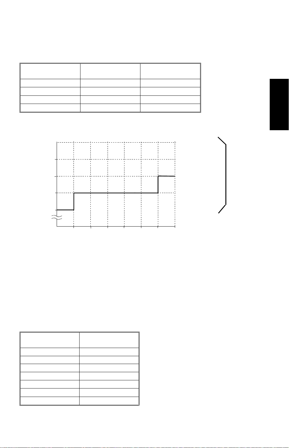
1.2.1 Manual ID Correction
If the user selects the image density man ua lly, th e selected manual ID level
affects the exposure la mp volt ag e an d th e de velopment bias as follows.
- Exposure Lamp Voltage -
As the ID level increases from 1 to 7, the exposu re lamp voltage is increased
as shown in the following table.
Table 1. Exposure lamp vol tage control by manua l ID level
ID Level Lamp Voltage
1 Vexp –4.0 V
2 Vexp –3.0 V
3 Vexp –1.5 V
4
5 Vexp +1.5 V
6 Vexp +4.0 V
7 Vexp +6.0 V
Vexp ±0.0 V
Vexp = Lamp voltage selecte d with SP4-001. It can be between 50 and 75 V.
It is factory set, and varies from copier to copier.
- Development Bias -
The greater the nega tive voltage, the paler th e imag e on the drum. However,
the development bias is adjust ed only at the extre me light and dark ends of
the manual ID range.
Table 2. Development bias control by manua l ID level
ID Level Development Bias
1 +80 V
2
3
4
5
6
7 SP2-201-002 (see below)
±0 V
±0 V
±0 V
±0 V
±0 V
Note: The base developme nt bias volt age is -2 40 Volt s.
2-8
Page 30
ID Level
–320
(Lighter)
–240
(Darker)
–360
(Lightest)
13th January 1995 PROCESS CONTROL
For ID Level 7 (lightest copie s), th ere are fo ur possible development bias
correction setting s tha t can be selected with SP2-20 1-0 02 , as sho wn be low.
Table 3. Lightest ID level developme nt bias (ID Leve l 7)
SP2-201-002 Setting Density
1 (Factory Setting) Normal –40 V
2 Dark
3 Lighter –80 V
4 Lightest –120 V
Dev. Bias
Correction Voltage
±0 V
In summary, the development bias at various ID level settings is shown below.
Development Bias Voltage
–320
SP2-201-002
–280
–240
–160
–280
(Normal)
1765432
for ID Level 7
Detailed
Descriptions
1.2.2 Reproduction Ratio Correction
At reproduction ratio s of 50 % an d 11 6% or g rea ter, the intensity of light
reaching the drum from the origin al drops significantly, which could cause
copies to become underexposed (too dark).
To compensate for th is, a de velopment bias correction voltage is applied as
shown in Table 4. This correction incre ases the development bias volta ge ,
restoring the copy image densit y to normal.
Table 4. Reproduction ratio correction
Reproduction
Ratio (%)
181 ~ 200 –100 V
161 ~ 180 –80 V
142 ~ 160 –60 V
123 ~ 141 –40 V
116 ~ 122 –20 V
51 ~ 115
50 –30 V
Development Bias
Correction Voltage
±0 V
2-9
Page 31

[A]
PROCESS CONTROL 13th January 1995
1.2.3 ADS Correction
ADS pattern
Fig. 3 ADS pattern
If the user selects Auto Image Density (ADS) mod e, the output of the ADS
sensor is used to correct the develop ment bias; the exposure lamp volta ge is
kept at the setting for ID level 4 and is not adjusted.
In ADS mode, the ADS sensor [A] detects the original background density.
To prevent dirty background from appearing on copies, the CPU corrects the
development bias vo lta ge for the original. To do this, it compa res the ADS
sensor output from the origin al [VADS (original)] with a stored reference value
[VADS (pattern)] that was taken earlier from the ADS sen sor pa tt ern . The
correction is shown in table 5, and is app lied every cop y.
Table 5. ADS data correction
ADS Density SP5-106
Setting Copy Density
0 Darker 816 x (AR – 0.79)
1 Normal 816 x (AR – 0.85)
2 Lighter 816 x (AR – 0.95)
Development Bias Correction Voltage
Where AR (ADS Ratio) = VADS (original)/VADS (pattern)
Note that there are three possib le corrections. The default sett ing is 1
(normal). However, for example , if the use r requ ires cop ies to be darker
when using ADS mode, a tech nicia n can set SP5-106 to 0.
VADS (pattern) is checked every 1,00 0 cop ies. (See process control checks
at every 1,000 copies on p2-29.) It is kept at 2.7±0.1 volts by a gain
adjustment.
See the "Optics - Automatic Image Density Cont rol Syst em (ADS)" section for
more details on how the ADS sensor mea sure s the backg rou nd and on how
[VADS (pattern)] is corrected every 1,000 copies.
2-10
Page 32

35 mm
13th January 1995 PROCESS CONTROL
1.3 IMAGE DENSITY CONTROL
1.3.1 Overview
The machine controls th e toner supply mechanism using th e toner density
sensor (TD sensor) and the image density sensor (ID sensor).
Readings from the TD sensor are use d to keep the ton er con cen tration in the
developer at a constant level. However, the image on the OPC drum varies
due to the variation in toner chargea bilit y, which is influenced by the
environment, eve n if th e toner concentration is con sta nt. Because of this,
readings from the ID sensor are used to cha ng e the tone r concentration to
keep the image density on the OPC drum constant.
1.3.2 VSP and VSG Detection
[D]
[C]
[A]
Drum
LED
ON
LED
ON
Detailed
Descriptions
V
SG
Dev.
V
SP
bias
[B]
65 mm
The ID sensor [A] (below the drum cleaning section) checks the follo wing
voltages.
• VSG: the ID sen sor outp ut when checkin g the era sed drum surface.
• VSP: the ID sen sor ou tput when checking the Vsp pat te rn image.
In this way, the reflectivity of both the erased drum surf ace and the patte rn on
the drum are checked. This compensates for any variations in light intensity
from the LED component of the sensor or the reflectivity of the drum.
The VSP pattern [B] is made on the OPC drum b y the drum cha rge roller [C]
and the erase lamp [D].
2-11
Page 33

VSP Detection
3rd Series of
Copies (17
copies)
PROCESS CONTROL 13th January 1995
VSP Detection
12345678 9101112
1st Series of Copies
VSG
(8 copies)
Detection
• VSG is measured at the start of every copy run.
• VSP is detecte d at the end of a copy run if 10 or more copies ha ve be en
V
SG
Detection
V
SP Detection
2nd Series
of Copies
(5 copies)
13
14 15
SG
V
Detection
29
30
31
V
SG
Detection
made since VSP was last measure d. The transfer belt must be rele ase d to
measure VSP, so it cannot be checked during a copy run .
1.3.3 ID Correction for the VSP Pattern
Background
Developer consists of carrier particles (fe rrite and resin) an d to ner p art icles
(resin and carbon). The positive trib oe lect ric ch arg e on the ton er is cause d by
friction between the carrier and to ne r part icles. However, the chargeability of
carrier decreases with time. Therefore, if the toner weight ratio in the
developer is the same, the amou nt of positive tribo electric charge for one
particle of toner decreases. This is becau se the number of toner particles
which surround one carrier particle is the same, but the charg ea bilit y of one
particle of carrier is less than before.
If the development pot en tia l, that is, the difference of voltage between the
development roller and the drum for the V SP pattern is the same, more toner
particles are attracted to the VSP pattern , because one particle of toner has
less positive charge than before. (Mo re tone r part icles are requ ired to
balance the charge of the VSP pattern.)
If the ID sensor were to check t he VSP pattern’s reflectivity unde r this
condition, the VSP pattern would be darker than before. The CPU would then
incorrectly conclude that the toner weight ratio in the deve loper is too high
even though the ratio actually re main s the same. The CPU wou ld th en
decrease the toner clutch on time, leading to a low percentage of tone r in the
developer by weight as the copy cou nt rises.
If uncontrolled, th is would cause some side effects, such as low image
density or developer adherin g to the copy. To prevent the se side eff ects, ID
correction is done when the VSP pattern is made.
2-12
Page 34

13th January 1995 PROCESS CONTROL
The idea behind ID correction is to cancel th e effe ct on the VSP pattern of the
decrease in the chargability of carrier with time. ID correction is done by
changing the develo pment bias for the VSP pattern so that it has the same
darkness even though the charg ea bility of the carrier has changed .
ID Correction Method
The machine determines whether the developme nt bias ne ed s adjusting by
monitoring the density of the toner/carrier mixtu re in the development unit .
When the toner weight ratio in the developer changes, the voltage output by
the TD sensor changes accordingly. The smaller the toner wight ratio in th e
developer is, the gre at er th e TD se nso r o ut pu t is, as sho wn in th e diagram
below.
Detailed
Descriptions
When new developer with th e sta nd ard concentration (2 .0 % by weight, 20 g
of toner in 1,000 g of developer) is installe d, the TD sensor initial setting must
be done with SP mode 2-214. This sets the sensor output to 2.5 ± 0. 1 V.
As shown earlier, the charge ab ility of carrier in the developer decreases with
the copy count. If no corre ction is done, the CPU tries to decre ase the ton er
weight ratio in the develo pe r. So this eventually causes the reading from th e
TD sensor to exceed its maximum acceptable value (initial value + 1. 0 V).
If the corrected TD sensor output VTREF exceeds the upper limit over 100
times continuously, development bias for the VSP pattern is corrected. VTREF
is the current TD sensor output wit h a corre ction factor included that is base d
on the VSP/VSG ratio from the ID sensor (see VSP and VSG Detection)
calculated every 10 copies or so (see Toner Supply Control - Detect Sup ply
Mode for more about VTREF).
The first time this happens, the correction is -40 V. If the upper limit is
exceeded 100 consecutive times ag ain later, an extra -40 V correction is
applied (see the following table). There sho uld be no need for furt her st eps,
because the toner proportion by weight will stabilize before this.
2-13
Page 35

PROCESS CONTROL 13th January 1995
Table 6. ID correction
Step Development Bias Correction for the VSP Pattern
Initial 0 V
1st –40 V
2nd –80 V
If no correction is applied, the charge on the drum for the VSP pattern is –600
V, and the developme nt bias fo r t he VSP pattern is –300 V. So there is a
difference of 300 V between the deve lopment roller and the drum for the VSP
pattern.
When the ID correction is applied, the voltage difference is reduced. For
example, if a –40 V ID correction is applied, the difference in voltage is:
Before ID Correction: –300 – (–600) = 300 V
After ID Correction: –300 – 40 – (–600) = 260 V
As a result, the effect of the change in chargeabilit y of the carrie r part icles is
canceled. The darkn ess of the VSP pattern returns to normal.
1.3.4 Toner Supply Control During Copying
There are three modes for con tro lling the toner supply.
• Detect supply mode
• Fixed supply mode
• TD sensor supply mode
The mode can be selected with SP2-208-001. The factory setting is detect
supply mode.
Toner clutch on time is calculated by the following formu la.
S x AT x TSC ⁄⁄ 100
Toner CL on time [ms] =
TS
(Formula 1)
where: S = Copy paper size [cm2]
AT = Amount of ton er de veloped on the latent ima ge per un it area
= 0.7 [mg/cm2] (constant)
TSC = Toner supply coefficient [% ]
TS = Amount of toner supplied per unit of time
= 0.183 [mg/ms] (for A153, A155, and A156 copiers)
= 0.133 [mg/ms] (for A157, A159, and A160 copiers)
AT and TS are constant, an d S de pe nd s only on pap er size, but TSC is
determined in different ways depending on which toner supply mode is in use.
2-14
Page 36

13th January 1995 PROCESS CONTROL
Determination of TSC
TSC is an estimate of the proportion of black area in the image that is made
by the machine.
(1) Detect Supply Mode
In detect supply mode, TSC is determined from out puts fro m bot h the TD and
ID sensors, in conjunctio n with the toner supply ratio that has been selected
for this mode.
- Toner Supply Ratio -
This is selected with SP2-22 2. Th e set tings are 1 (7%), 2 (15%), 3 (30%), or
4 (60%). The default is 15%.
- TD and ID Sensor Outputs -
The machine calculates a value for VT-VTREF.
VT: Current TD sensor output
•
• VTREF: TD sensor output at the latest V SP detection corrected for ID
sensor output (VSP/VSG); this is calculat ed every 10 or so copies (see
VSP/VSG Detection for more on VSP and VSG).
VTREF is determined as follows.
VTREF = VTP + ∆∆ VREF (Formula 2)
VTP = TD sensor output at VSP detection
•
• ∆VREF = Correction factor based on VSP/V SG (from the ID sensor
output), determined by the following table.
Table 7.
VSP pattern
darker
VSP pattern
lighter
VSP/VSG
~ 0.075 +4 x 0.0196
0.076 ~ 0.090 +2 x 0.0196
0.091 ~ 0.105
0.106 ~ 0.125 –2 x 0.0196
0.126 ~ 0.160 –4 x 0.0196
0.161 ~ 0.205 –6 x 0.0196
0.206 ~ 0.500 –8 x 0.0196
0.501 ~ The previous V
∆∆ VREF [V]
±0
TREF
Detailed
Descriptions
TSC [%] is then determined from VT-VTREF and the toner supply ratio, as
shown by table 8.
2-15
Page 37

PROCESS CONTROL 13th January 1995
Table 8. Toner Supply Coefficient (%)
(VT-VTREF)
/0.0196
~ 0 0 0 0 0
1 ~ 3 7 15 30 60
4 ~ 5 15 30 45 60
6 ~ 7 30 45 60 60
8 ~ 60 60 60 60
Supply Ratio (SP Mode Setting)
7% 15% 30% 60%
For example, if the toner sup ply rat io is 15% and (VT-VTREF)/0.0196 is 4.5,
TSC is 30. This value is then used in the formula to determine the toner
supply clutch on time given at the sta rt of this discussion. (See formula 1.)
This all means that, if the ID sensor reading indicated that the most recent
VSP pattern was relatively light, th e toner supp ly clutch will stay on for long er.
(If VSP/VSG is higher, ∆∆ VREF is smaller [Table 7]. This means th at VTREF is
smaller [Formula 2], leading to a larger V T -VTREF. So, for a part icula r ton er
supply ratio, the TSC valu e will be higher [Table 8], so the clut ch stays on for
longer [Formula 1].)
(2) Fixed Supply Mode
TSC [%] is fixed. It is selected with SP mode 2-208-003 as shown below.
Table 9. Toner Supply Coefficient (%)
SP2-208-003 Value
1234
TSC [%] 2 4 6 11
NOTE: Default = 6%
The machine automatica lly switches to fixed supply mode if the ID or TD
sensor fail (see section 1.3.5.).
(3) TD Sensor Supply Mode
TSC [%] is determined as shown in Table 8 fo r det ect supp ly mode .
However, the toner supp ly ratio and V T – V TREF are both determined in
different ways. In particular, the ID sensor outp ut is ignored.
- Toner Supply Ratio -
The supply ratio is selected with SP2-208-002. The set tings are 1 (7%), 2
(15%), 3 (30%), or 4 (60%). The default is 15%.
- VT – VTREF -
• VTREF = VTREF at the moment that TD sensor supply mode was selected.
• VT = Current TD sensor output
1.3.5 Toner Supply in Abnormal Sensor Conditions
2-16
Page 38

13th January 1995 PROCESS CONTROL
If any sensor errors occur under dete ct sup ply mode, toner supply mode is
changed automatically as shown be low.
Table 10.
Error Abnormal Condition
ID Sensor
Adjustment Error
Abnormal ID
Sensor (V
Abnormal ID
Sensor (V
TD Sensor
Adjustment Error
TD Sensor (V
Measurement Error
Drum Charge
Thermistor Error
Abnormal Drum
Charge Thermistor
Output
SP)
SG)
T)
When ID sensor output
cannot be adjusted to 4.0 ±
0.2 V
If V
SP > 2.5 V during VSP
detection.
If V
SG < 2.5 V during VSG
detection
When TD sensor output
cannot be adjusted to 2.5 ±
0.1 V
If VT > 4.0 V or VT < 0.3 V
during V
Temperature detected by the
drum charge thermistor is
below 0°C or above 60°C
Temperature detected by the
drum charge thermistor (T) is
between 0 °C and 20°C
T detection.
Fallback Toner
Supply Mode
Fixed Supply Mode None
Fixed Supply Mode
Fixed Supply Mode
Fixed Supply Mode
Fixed Supply Mode
Fixed Supply Mode None
TD Sensor Supply
Mode
Display on
Operation Panel
None
Manual ID level or
ADS indicator
blinks
Manual ID level or
ADS indicator
blinks
None
NOTE: No indicat ion is displayed under the "abnormal drum ch arg e
thermistor output" con dition, because the mach ine soon recovers due
to the heat inside th e mach ine.
Detailed
Descriptions
2-17
Page 39

Drum
residual
voltage
Light intensity
PROCESS CONTROL 13th January 1995
1.4 DRUM POTENTIAL CONTROL
The characteristics of the drum vary with the tempe rat ure arou nd the drum,
and they change as the drum gets older. To take account of these and other
related factors, this machine has the following three drum potential con tro l
routines.
• VR pattern correction
• VL pattern correction
• T/H correction
1.4.1 VR Pattern Correction
(V)
Copy volume
(V)
Drum
potential
Old Drum
New Drum
As the drum ages, the drum residual volta ge grad ua lly increases due to
electrical fatigue (see the upper left chart ). In other words, as the drum gets
older, light does not discharg e it as much (see the upper right chart). This
may cause dirty background on copies. VR pattern detection every 1,000
copies using the ID sensor avoids this problem.
0V Bias
VRP
VR Pattern
ID Sensor
Every time VR pattern detectio n is don e, a strip acro ss the drum is charg ed
using zero development bias an d th e standard charge on the drum cha rge
roller that is used for copyin g (with all corrections included). At the same time ,
all the blocks of the erase lamp turn on to illumin at e this charged area of the
drum.
2-18
Page 40

ID correction
0 V
–40 V
–80 V
13th January 1995 PROCESS CONTROL
If there is residual volta ge on th e dru m, this area of the drum will attra ct some
toner, making a VR pattern. The ID sensor che cks the refle ctivity of the VR
pattern. This sensor output voltage is VRP.
In VR detection, VRP is compared with VRG.
• VRG is the reflectivity of the bare area of the drum, measured by the ID
sensor. It has the same value as VSG (see Image Density Con tro l - VSG
and VSP Detection).
• VRP is the output from the ID sensor reflected from the VR pattern.
When the drum residual voltage increases, the VR pattern becomes darker.
Then, VRP decreases and the VRP/VRG ratio decreases.
Then the CPU increases the ne ga tive development bias voltage to prevent
dirty background, and simultane ou sly increa ses the negative drum charge
roller bias voltage to preven t low imag e densit y. This is t he VR correction.
Table 11. VR correction
RP/VRG
V
x 100(%)
ID Correction Drum Charge Roller
±±0 V
64 ~ 100 60 ~ 100 54 ~ 100
47 ~ 63 42 ~ 59 36 ~ 53 –40 V –40 V
35 ~ 46 30 ~ 41 24 ~ 35 –80 V –80 V
26 ~ 34 21 ~ 29 16 ~ 23 –120 V –120 V
0 ~ 25 0 ~ 20 0 ~ 15 –160 V –160 V
–40 V –80 V
Correction Voltage
±0 V ±0 V
Development Bias
Correction Voltage
For example, taking th e ID correction to be zero for now, if VRP/V RG is 45%,
the drum charge and development bias corrections will both be -80V.
VR correction also depends on the current VSP pattern ID correction that is
being used. If develo pment bias has been increased by ID corre ction, the VR
correction may be smaller in some cases t o take this into account. This is
shown by both the table above and the following figure.
Detailed
Descriptions
2-19
Page 41

PROCESS CONTROL 13th January 1995
Using the same example to illustrate this, but with an ID correction of -40 V,
the corrections will both be -40 V this time.
Note that forced VR detection by SP mode must be done when a new drum is
installed or the ID sensor cle aned or repla ced. (See Service Tables Practical SP Mode Use Tables for the corre ct sequence of SP modes to
perform at this time). The correction is done in the same way as describe d
above.
2-20
Page 42

13th January 1995 PROCESS CONTROL
1.4.2 VL Pattern Correction
VL Pattern
ID Sensor
(V)
Drum
Potential
Initial
Conditions
Exposure lamp voltage
Deteriorated
Conditions
(V)
Dirty optics or deterioration of th e exposure lamp decreases the intensit y of
the light that reaches the drum via th e optics cavit y. As more copies are
made during the drum’s life, the photoconductive layer gets worn and the
response of the dru m to th e exposure lamp weakens.
VL pattern correction counteracts dirty backg rou nd caused by the factors
mentioned above.
The VL pattern is a light gray sensor pattern on the ope rator side of the
bottom of the left scale bracket. The ID sensor outp ut at VSG dete ctio n in
memory is used again as VLG (the refle ctivit y of the bare are a of the drum).
Detailed
Descriptions
When VL pattern de te ction starts, the exposure lamp turns on and the main
motor stays on to rotate the dru m. The drum charge roller, all the blocks of
the erase lamp, the pre-transfer lamp, and the quenching lamp turn on. Then,
the appropriate blocks of the era se lamp turn off and on to ma ke a VL pattern
on the drum surface.
In VL detection, VLP is compared with VLG.
• VLG is the reflectivity of the bare area of the drum, measured by the ID
sensor. It has the same value as VSG (see Image Density Con tro l - VSG
and VSP Detection).
• VLP is the output from the ID sensor reflected from the VL pattern.
2-21
Page 43

PROCESS CONTROL 13th January 1995
VL detection is done at the following times:
• Every 1000 Copies
• Forced Detection: whenever a new drum or exposure lamp is installed, or
exposure lamp voltage is adjust ed , or whe n the optics are cleaned, forced
VL detection (SP3-105 ) must be execu te d. (S ee Service Ta ble s - Practical
SP Mode Use Tables for the correct seque nce of SP modes t o perfo rm at
this time).
Forced VL detection is differe nt from th e routine 1,000 copy VL detection,
so it is explained below in detail.
During forced VL detection, BL and VREF are determined as shown below.
NOTE: BL = Development bias used for VL correction.
SP3-105
START: BL = -50V
BL= BL -20V
Fig. 19
VLP, VLG detection
NO
VLP/VLG > 0.45?
BL = current BL
V
REF
_
YES
= VLP/V
LG
BL starts at -50 V and -20 V is added until the value of VLP is appropriate.
VL Correction Method
During VL pattern de te ctio n, lamp volt ag e, drum cha rge voltage and
development bias are as follows.
• Lamp voltage: same as during normal copying (ADS mode)
• Drum charge voltage for the VL pattern: same as du ring norma l co pyin g
• Development bias for forced VL detection: BL + VR correction + VBL(ID)
Development bias for VL detection every 1000 copies:
•
= BL + (–25 V) + VR correction + VBL(ID)
VBL (ID) is an ID compensation fact or ba sed on th e curre nt ID correction
used for the VSP pattern (see Image Density Control fo r det ails on this ID
Correction). It is applied as sho wn in Tab le 12 .
Table 12
ID correction 0 V –40 V –80 V
V
BL(ID)
±0 V
–10 V –20 V
2-22
Page 44

ID correction
0 V
–40 V
–80 V
13th January 1995 PROCESS CONTROL
- Forced VL Detection -
When forced VL detection (SP3-105) is exe cut ed , th e CPU sto res the VL
reference value (V REF) in memory (see Fig. 19).
VREF = initial VLP/VLG
- Every 1,000 copies -
After the forced VL detection , V L de te ction is performed at the end of eve ry
1000 copies. The VLP/V LG value at that time is called VDAT.
VDAT = current VLP/VLG
- During Copying -
The CPU compares the late st VDAT with the latest VREF and applies a VL
correction to the exposure lamp voltage as shown below.
Table 13. VL Correction
ID Correction Lamp
±±0 V
–40 V –80 V
Correction
Voltage
Detailed
Descriptions
DAT/VREF
V
x 100 (%)
146 ~ 156 ~ 168 ~ –1 V
101 ~ 145 101 ~ 155 101 ~ 167
~ 100 ~ 100 ~ 100 +1 V
±0 V
In general, the lamp will be dimmed slightly if the VLP pattern reflectivity has
increased significan tly (th e V LP patte rn is pale r), and mad e bright er if th e
reflectivity has decreased (the VLP pattern is darker).
VL correction also depends on the current VSP pattern ID correction that is
being used (see Image Den sity Con trol - ID Correction for the V SP pattern).
For example, taking th e ID correction to be zero for now, if VDAT/VREF is
150%, the lamp correction will be -1V (made slightly dimmer). Usin g the
same example, but with an ID correction of -40V, the correction will be 0 V
this time.
2-23
Page 45

PROCESS CONTROL 13th January 1995
1.4.3 T/H Correction
Potential of new drum
Change in drum potential
with use
The drum charge efficiency is t he ratio of the charge actually on the drum to
the charge that was applied to the dru m. It varies with the temperature
around the drum charge roller. It dro ps of f at lower te mpe rat ures, so the
lower the temperature is, the high er th e cha rge tha t is required.
Also, as the drum ages, the photocon du ctive layer ge ts worn . This cau ses a
decrease in the drum pote nt ial after charging.
The drum charge thermistor detects the tempe rat ure (T) aro und the dru m
charge roller. The drum charge ro ller volt ag e is chan ged to account for the
effects of temperat ure on dru m charg e ef ficiency.
The CPU also keeps track of the drum rotat ion time (H) that corresponds to
the wear on the drum surface. The drum cha rge roller voltage is increased at
set intervals.
These corrections for the drum charg e rolle r volta ge are calle d T/H corre ctio n.
The T/H correction that is applie d du ring copying differs from that applied
when making ID sensor patterns. See below for how the correction is
determined.
The T/H correction difference be twe en the A15 3, A155, and A15 6 copiers
and the A157, A159, and A160 copiers is a result of th e dif ference in copy
processing speed (200 mm/s fo r the A15 3, A155, and A15 6 copiers,
compared with 150 mm/s for the A157, A159, and A160 copiers).
2-24
Page 46

13th January 1995 PROCESS CONTROL
Table 14. T/H Correction (Copying) - Base drum charge voltage = -1500 V
A153, A155, and A156 copiers
Drum Charge Roller
Temperature (T )
37.1 ≤ T
29.6 ≤≤ T < 37.1
17.9 ≤≤ T < 29.6
12.6 ≤≤ T < 17.9
T < 12.6 -639.0 -800.0 -961.0
0 ≤≤ H < 40 40 ≤≤ H < 110 110 ≤≤ H
-60.0 -60.0 -60.0
-203.4 + 3.9xT -203.4 + 3.9xT -203.4 + 3.9xT
-729.1 + 21.6xT -923.9 + 28.2xT -1116.1 + 34.7xT
-1345.1 + 56.0xT -1705.8 + 71.9xT -2068.9 + 87.9xT
Drum Rotation Time (H)
A157, A159, and A160 copiers
Drum Charge Roller
Temperature (T)
32.4 ≤≤ T
28.2 ≤≤ T < 32.4
18.0 ≤≤ T < 28.2
12.4 ≤≤ T < 18.0
T < 12.4 -530.0 -669.0 -808.0
0 ≤≤ H < 40 40 ≤≤ H < 110 110 ≤≤ H
-80.0 -80.0 -80.0
-426.7 + 10.7xT -426.7 + 10.7xT -426.7 + 10.7xT
-621.8 + 17.6xT -768.4 + 22.8xT -912.2 + 27.9xT
-1028.6 + 40.2xT -1357.2 + 55.5xT -1689.7 + 71.1xT
Drum Rotation Time (H)
Table 15. T/H Correction (VSP Pattern) - Base drum char ge = -1300 V
A153, A155, and A156 copiers
Drum Charge Roller
Temperature (T)
37.1 ≤≤ T
29.6 ≤≤ T < 37.1
17.9 ≤≤ T < 29.6
12.6 ≤≤ T < 17.9
T < 12.6 -387.0 -508.0 -629.0
0 ≤≤ H < 40 40 ≤≤ H < 110 110 ≤≤ H
+40.0 +40.0 +40.0
-103.4 + 3.9xT -103.4 + 3.9xT -103.4 + 3.9xT
-489.9 + 16.9xT -603.8 + 20.8xT -717.6 + 24.6xT
-862.5 + 37.7xT -1164.2 + 52.1xT -1465.9 + 66.4xT
Drum Rotation Time (H)
Detailed
Descriptions
A157, A159, and A160 copiers
Drum Charge Roller
Temperature (T)
32.4 ≤≤ T
28.2 ≤≤ T < 32.4
18.0 ≤≤ T < 28.2
12.4 ≤≤ T < 18.0
T < 12.4 -331.0 -426.0 -520.0
0 ≤≤ H < 40 40 ≤≤ H < 110 110 ≤≤ H
+24.0 +24.0 +24.0
-283.9 + 9.5xT -283.9 + 9.5xT -283.9 + 9.5xT
-402.6 + 13.7xT -532.4 + 18.3xT -662.2 + 22.9xT
-719.3 + 31.3xT -919.5 + 39.8xT -1117.6 + 48.2xT
Drum Rotation Time (H)
For example, when copying with an A157 copie r at 25 °C with a dru m t hat ha s
a rotation time of 100 hours:
• The T/H correction is -768.4 + (22.8 x 25) V = -198.4 V.
• The drum charge roller voltage is the base voltage plus the T/H correction
= (-1500) - 198.4
= -1698.4 V.
2-25
Page 47

PROCESS CONTROL 13th January 1995
1.5 PROCESS CONTROL DURING ABNO RMAL CONDI TI O N S
When an abnormal sensor condition occurs, some process controls are
disabled.
Abnormal
Condition
Thermistor Error
TD Sensor
Adjustment Error
TD Sensor
Detection Error
SP Error
V
V
L Error
ID Sensor
Adjustment Error
SG Error
V
ID Sensor
Adjustment
Executed
Process Control
R Correction VL Correction
V
Disabled
ID sensor adjustment error → Disabled
If the ID sensor can be adjusted → Executed
ADS Sensor
Adjustment
2-26
Page 48

13th January 1995 PROCESS CONTROL
1.6 SUMMARY
1.6.1 Process Control and Sensor Detection Timi ng
A summary of process control and correction timing is shown below.
Correction
Manual ID
correction
Reproduction
ratio
correction
ADS
correction
ID
correction
and
Toner
density
control
R
V
correction
V
L correction
T/H
correction
Electrical
Component
Sensor
Output Used
Correction Timing
Forced
Correction
Operation
panel
——
Operation
panel — —
ADS sensor
VADS (pattern)
V
ADS (original)
—
New drum,
ADS sensor,
or exposure
lamp
ID sensor V
SG New drum or
ID sensor
replacement
TD sensor V
SP About every
V
T When the
developer is
changed
ID sensor V
RP, VRG New drum or
ID sensor
replacement
ID sensor V
LP, VLG New drum or
exp. lamp
• Drum
charge
roller
thermistor
• RAM Board
T:
(temperature)
H:
(drum
rotation time)
H is reset at
the drum
initial setting
Automatic
Correction
Every copy in
manual ID
mode
Every copy in
reduce/enlarge
mode
• ADS Mode:
Once per
original
(ARDF
mode), or
once when
the Start
key is
pressed
(Platen
mode)
Every 1000
copies
At the start of
each copy job
10 copies
Every copy
After every
1000 copies
Every copy
Corrected
Value
• Lamp
voltage
• Dev. bias
Development
bias
Development
bias
• VADS
(pattern)
is
stored
• Dev. bias
• Toner
supply
clutch ON
time
• Drum
charge
roller
voltage
• Dev. bias
Lamp voltage
Drum charge
roller voltage
Detailed
Descriptions
2-27
Page 49

PROCESS CONTROL 13th January 1995
1.6.2 Process Control Checks During Machine Operation
This section shows what the machine checks and recalibrates to cont rol the
copy process at different times.
Every Copy
The machine automatica lly adjusts the following process con tro l p ara met ers
every copy.
Uses:
IMAGE DENSITY
CONTROL
VSG Correction
Done at the start of every
copy run
ID Sensor
Affects:
Development bias
Toner supply clutch on time
IMAGE DENSITY
CONTROL
T
V
Correction
DRUM POTENTIAL
CONTROL
T/H Correction
Reduce
or Enlarge
Mode?
Which ID Mode?
MANUAL
Done every copy
Done every copy
YES
ADS
COPY IMAGE CONTROL
Reproduction Ratio
Correction
COPY IMAGE CONTROL
ADS Correction
Uses:
TD sensor
Affects:
Development bias
Toner supply clutch on time
Uses:
Drum charge thermistor
Drum rotation time to date
Affects:
Drum charge roller voltage
Uses:
Selected reproduction ratio
Affects: Development bias
Done: Every copy
Uses: ADS sensor
Affects: Development bias
Done:
Single copy of an original Every copy
More than one copy of the
same original Every copy (but only for the
first copy run)
COPY IMAGE CONTROL
Manual ID Correction
IMAGE DENSITY
CONTROL
VSP Detection
Uses:
Selected image density setting
Affects: Development bias
Exposure lamp voltage
Done: Every copy
Done at the end of the copy
run if more than 10 copies
have been made since the
previous V
SP
detection.
2-28
Uses: ID Sensor
Affects: Development bias
Toner supply clutch on time
Page 50

13th January 1995 PROCESS CONTROL
Every 1000 Copies
After every 1,000 copies, the machine calibrates the following reference
values for the various pro cesses that are used in process cont rol.
NOTE: If the aut o pro cess con trol mode has been disabled wit h SP 3-801,
this process control cycle will not be perfo rmed .
Uses:
IMAGE DENSITY CONTROL
SG
Reset
V
Resets VSG to 4 ± 0.2 V.
ID sensor
Affects:
Development bias
Toner supply clutch on time
Detailed
Descriptions
DRUM POTENTIAL
CONTROL
R
Correction
V
DRUM POTENTIAL
CONTROL
L
Correction
V
COPY IMAGE CONTROL
Auto ADS Gain Adjustment
Measures V
Sets VRG = V
Measures V
Sets VLG = V
Adjusts ADS sensor ouput
voltage for the ADS
sensor pattern to 2.7 ± 0.1
V.
After Adding New Developer
RP
LP
SG
SG
Uses:
ID sensor
Affects:
Development bias
Drum charge roller voltage
Uses:
ID sensor
Affects:
Exposure lamp voltage
Uses:
ADS sensor output
Affects: Development bias
The technician must do the follo wing SP mode after adding new de velo pe r.
SP 2-214
IMAGE DENSITY CONTROL
TD Sensor Initial Setting
Resets the TD sensor output to 2.5 ± 0.1 V
Resets ID correction for the V
SP
pattern to
zero (this affects development bias and
exposure lamp voltage)
2-29
Page 51

PROCESS CONTROL 13th January 1995
After Installing a New Drum
The technician must do a series of SP mod es to reset the process control
parameters related to the drum.
SP 3-123
Resets the following
V
correction level
DRUM INITIALIZATION
R
V
correction level
L
T/H correction level
Drum rotation time
IMAGE DENSITY CONTROL
CONTROL V
SG
Reset
V
DRUM POTENTIAL
Exposure Lamp Voltage
R
Detection
ADJUSTMENT
SP 3-001
Adjusts V
to 4 ± 0.2 V
SG
SP3-112
Detects the initital V
R
value for the new drum
SP4-001
See "Removal and Adjustment Copy Quality Adjustments"
COPY IMAGE CONTROL
Auto ADS Gain Adjustment
DRUM POTENTIAL
CONTROL
L
Detection
V
SP 4-201
Adjusts the ADS sensor
output to 2.7 ± 0.1 V
SP 3-105
Detects the initial V
value for the new drum
2-30
LP/VLG
Page 52

Development bias, dr um charge voltage, and e xposure lamp voltage
6th January 1995
The following table shows how process control affects development bias, drum charge, and exposure lamp voltages for various machine
operations.
Mode Development Bias [V] Drum Charge Voltage [V] Exposure Lamp Voltage [V]
2-31
Reproduction
correction
Reproduction
+
ratio
correction
Reproduction
+
correction
ratio
ratio
Copying
ADS mode
Manual
ID
mode
ID
Level
1 ~ 6
ID
Level
7
(–240) + ADS correction +
(–240) +
(–240) +
Manual ID
correction
Lightest ID level
dev.
bias
VSP Pattern Detection (–300) + BP + ID correction
VR Pattern Detection 0
VL
Pattern
Detection
Non Image Area
Forced VL
Detection
VL Detection
Auto ADS Gain
Adjustment
BL +
correction
BL + (–25) +
(–200) +
VR
+ VBL (ID)
VR
correction
VR
correction
+ VBL (ID) Vexp +
+ VBL (ID)
00
+
VR
+
correction
VR
correction
VR
+
correction
+ B
+ B
+ B
(–1500) +
(–1300) +
(–1500) +
VR
correction
correction
VR
correction
+
T ⁄ H
+
T ⁄ H
correction
+ CP
T ⁄ H
correction
+ C
+ C
0 0
Vexp +
Vexp +
Manual ID
Vexp +
correction
correction
0
0
Vexp
correction
correction
VL
+
VL
VL
VL
correction
NOTE:
B = Development bias adjustment factor, selected with SP2-201-001.
BP = Correction to the development bias used for making for V
SP patterns, selected with SP2-203.
BL = The value of the development bias that was reached during the most recently performed forced V
V
BL (ID) = ID compensation factor based on the current ID correction used for making VSP patterns.
C = Correction to the drum charge voltage, selected with SP2-001.
CP = Correction to the drum charge voltage for maknig V
SP patterns, selected with SP2-003.
Vexp = Exposure lamp voltage, selected with SP4-001.
PROCESS CONTROL
L detection routine.
Page 53

1
DRUM 13th January 1995
2. DRUM
2.1 DRUM UNIT
4
5
6
The drum unit consists of the components shown in the ab ove illustration. An
organic photoconductor (OP C) drum (dia met er: 60 mm) is used for this model.
3
7
2
8
1. OPC Drum
2. Drum Charge Roller
3. Drum Charge Roller Cleaner
4. Drum Charge Thermistor
5. Cleaning Blade
6. Pick-off Pawl
7. ID Sensor
8. Recycled Toner Transport
Coil
2-32
Page 54

13th January 1995 DRUM
2.2 DRIVE MECHANISM
[A]
Detailed
Descriptions
[D]
[C]
[B]
The drive from the main motor is transmitted to the drum drive pulle y via the
timing belt [A]. The pick-off pawls [B] are alwa ys in contact with the drum
surface under a weak spring pre ssure . The y mo ve fro m sid e to side du ring
the copy cycle. This movement is made with a worm g ear [ C] and an
eccentric cam gear [D].
2-33
Page 55

DRUM CHARGE 13th January 1995
3. DRUM CHARGE
3.1 OVERVIEW
[C]
[A]
[B]
[D]
This copier uses a drum charge rolle r system inst ea d of a coron a wire
scorotron system to charge the drum. For the copy ima ge area or during
process control, the drum charge roller [A] contacts the surface of the OPC
drum [B] to give a sufficient negat ive cha rge .
The drum charge roller system has the follo wing advantages over the coron a
wire scorotron system:
• The amount of ozone generated durin g dru m ch arg ing is less than 1/100
of that for a corona wire scorotron system.
• The applied voltage is 1/2 ~1/3 that of a wire scorotron system.
• The efficiency of drum charging is high.
Thanks to the above advantages, no ozone filter is required for this copier.
The CB high voltage supply bo ard [C] gives a constant dc voltag e of –15 00 V
(–1300 V fo r the VSP pattern) to the drum charge roller at the charge roller
terminal [D]. This gives the drum surf ace a negat ive cha rge of –900 V (–600
V for the VSP patte r n).
2-34
Page 56

[C]
13th January 1995 DRUM CHARGE
3.2 DRUM CHARGE ROLLER DRIVE MECHANISM
[G]
[H]
[B]
[F]
Home Position
[B]
[D]
[C]
[E]
[F]
[A]
During Image
Processing
Detailed
Descriptions
[C]
[B]
The drum charge roller is
away from drum
The drum charge roller
contacts the drum
To prevent toner from a dh erin g to the drum charge roller and to prevent the
drum charge roller from sticking to the OPC drum, the drum cha rge roller
contacts the OPC drum only under the following conditions:
(1) When the image processing area comes under the drum charge roller
(2) When process control is executed.
This function is performe d by the transfer belt conta ct clutch [A] (a one-third
turn clutch) with cam [B] located on the rear side plat e of the copier. When
the clutch [A] is driven one third of a complete rota tion, the cam [B] downs up
the lever [C]. The lever is linked with the plate [D] which releases th e on -of f
lever [E] of the drum charge roller. Then the drum charge roller contacts th e
drum as a result of the pressure from t he two sprin gs [F]. At the same time,
plate [D] also pushes the lever [G ] on the drum cha rge the rmisto r [H]. Then,
the drum charge thermistor moves awa y from the drum charge roller. When
the start key is pressed, the te mperature around the drum chanrg e roller is
measured while the drum charge thermist or con ta cts th e drum charge roller.
After that, the te mperature is measured while the drum cha rge thermistor is
away from the drum charge roller.
2-35
Page 57

DRUM CHARGE 13th January 1995
[A]
[B]
[A]
When the drum charge roller does not con ta ct th e dru m, th e dru m charg e
roller is driven by the main motor through some gears [A ]. (The rolle r spee d is
50 rpm for A153, A155, and A156 copiers, and 37 rpm for A157, A159, and
A160 copiers.) At this time, the roller touches the cleaning pad, and this helps
keep the roller clean, although a cleaning routine automatically takes place at
the end of every copy cycle (see below).
When the drum charge roller contacts the drum, th e force (to rqu e) imparted
by the drum becomes greate r tha n th e force transmitted through the clutch
[B]. Then, the drum charge roller rot at es with the drum rot at ion .
The drum charge roller comes away from th e dru m aft er every copy job. For
2 seconds after the end of every copy job and for 10 secon ds af te r every
copy interval set by SP2-9 01 , the drum charge roller is driven by th e main
motor via gears [A] for cleanin g (see "Drum Cha rge Roller Cleaning").
After cleaning, the main mot o r sto ps. While the main motor is not rot at ing, the
drum charge roller is kept away from the drum. This prevents the drum
charge roller from adhering to the drum.
2-36
Page 58

13th January 1995 DRUM CHARGE
3.3 DRUM CHARGE ROLLER CLEANING
[D]
[A]
[C]
[B]
If the drum charge roller get s dirty, drum cha rge eff iciency decreases. This
affects the copy quality, fo r example causing vertical white lines.
While the drum charge roller is away from the drum but still rota tin g, it
brushes against the clea ning pad [A], which helps to keep it cle an .
However, there is a specific dru m charg e rolle r cle aning routine which is
described below. It is executed at the following int erva ls:
(1) For 2 seconds at the end of every job
(2) For 10 seconds after the cop y jo b int erval set by SP2-901.
Detailed
Descriptions
After the copy job, the drum cha rge roller comes away from the drum and
contacts the drum charge roller clea ne r pad [A] . The main mot or still rotates
during cleaning and drive s the gea r [B] to swing the le ver [C] via an ecce nt ric
cam. This lever swings the arm [D] and the arm gives a side-to-side
movement to the drum charge roller cleaner.
The cleaning interva l set by SP2-901 is as follows:
SP2-901 setting: 0: Every 1000 copies (10 seconds) [de fa ult ]
1: Every 500 copies (10 seconds)
2: Every 200 copies (10 seconds)
3: Every 100 copies (10 seconds)
For a user who mainly makes consecutive high volume copy runs, the drum
charge roller is likely to get dirty early, becau se th e interval between jobs
(and thus the interval between end-of-copy-job cleaning runs) is longer than
for small volume intermitte nt copy runs. In this case, the copy co un t int erval
for cleaning must be reduced with SP2-901, to have the ten-second cleaning
routine done more often.
2-37
Page 59

DRUM CHARGE 13th January 1995
3.4 TEMPERATURE COMPENSATION
[A]
[B]
The required applied voltage varies with the temperature around the drum
charge roller. The lower the tempe rature is, the higher the applied volt age
required. This affects the drum charge efficie ncy.
To compensate for these characteristics, the drum charge thermistor [A]
detects the temperature aro un d the dru m ch arg e rolle r. Be fo re the cop y jo b
starts, the drum charge thermistor con ta cts the dru m charg e rolle r, T/H
correction for the first copy use s the temp era tu re de tected while the drum
charge thermistor contacts th e dru m charge roller. After the coy job starts, the
thermistor is away from the drum charge roller. Af te r the 2nd copy, T/H
correction uses the te mpe rature detected while th e dru m charge thermistor is
away from the drum charge roller. Using the detecte d temperature, T/H
correction is performed. (Se e "T/ H correction" in the Process Control sectio n
for details.)
To avoid low drum charge efficien cy for the first copy after the main switch is
turned on, there is a drum heater [B] located over t he drum an d drum charge
roller. This heater is turned on while the copier main swit ch is turn ed off . It
keeps the temperature aro un d the dru m and drum cha rge ro ller ove r 15°C.
For this heater to operate, the power cord of the copie r mu st be plug ge d in
even when the main switch is turned off.
2-38
Page 60

13th January 1995 OPTICS
4. OPTICS
4.1 OVERVIEW
[A]
The optics unit reflects an image of the origin al on the expo sure glass onto
the OPC drum. This forms a latent electrical image of the origin al.
In this model, a halogen lamp is used for the exposure lamp [A] . The lamp
surface is frosted to ensure even exposure. The specificat ions of the lamp
are as follows. Note that the A153/155/156 models are faste r, so th ey need
more light during exposure .
[B]
[C]
[E]
[D]
Detailed
Descriptions
115V Machines 230V Machines
A153/A155/A156 97V 280W 85V 280W
A157/A159/A160 97V 200W 85V 200W
Six mirrors are used to make the optics unit smaller and obtain a wide
reproduction ratio ran ge (50 ~ 200 %).
[B]
(2)
(1)
(1)
(2)
[C]
(3) (3)
The lens [B] is driven by two stepper mo to rs f or (1) vert ical move ment
(parallel to the paper feed direct ion ) and (2) horizo ntal movement. Also, to
correct for focal length chang e in red uct ion and enla rge men t modes, the third
scanner unit [C] (4th and 5th mirrors) is moved (3) vertically (pa ralle l to th e
paper feed direction) by another stepper mot or.
A toner shield glass [D] and a green filte r [E] are installed above the OPC
drum to improve red original re pro du ctio n.
2-39
Page 61

OPTICS 13th January 1995
The CPU monitors the tempera tu re aro un d the optics cavity through a
thermistor which is under the left scale . Whe n th e dete cte d te mpe rat ure
reaches a certain threshold value (see the following table), the optics cooling
fan(s) on the rear of the optics side plat e starts to draw cool air into the optics
cavity. The hot air exits through the ven ts in th e uppe r cover. Th e fan(s)
operate until the temperature drop s belo w t he thre shold temperature. Note
that the A153/155 /156 models have two fans; this is b eca use the exposure
lamp is more powerful in this model, so more cooling is neede d.
A153/A155/A156 A157/A159/A160
Rotating temperature
Number of fans 21
45°C40°C
The thermofuse (loca ted on the 1st scanner) provides ba ck-up overheat
protection. It ope ns at 121°C and removes ac power to the exposure lamp.
The thermofuse is not resettable.
An optics anti-condensation heater is availab le as op tio nal equ ipme nt (it is
also a service part). To prevent moistu re fro m f ormin g on the opt ics, it tu rns
on while the main switch is turned off.
The main board controls t he expo sure la mp volt ag e th rough the ac drive
board. The exposure lamp voltage is based on the base lamp voltage (set by
SP4-001) and various correctio n factors. The corrections depend on whet her
the image density is manually selected or whether ADS mode is selected. For
details, see Process Control - Summary.
2-40
Page 62

[F]
[I]
13th January 1995 OPTICS
4.2 SCANNER DRIVE
[D]
[E]
[H]
[G]
[A]
[B]
[C]
In this model, a stepper motor [A] drives the scanners via a timing belt [B],
scanner drive pulley [C], and two lon g & sho rt scanner drive belts [D,E]. To
prevent skewing, both ends of each scanner are driven. The scanners have
sliders [F], which ride on guide rails.
Unlike previous models, the scan ne r drive pu lleys are made of alu minu m.
Also, bearings at the en ds of the scann er drive pulley shaft assure reliable
scanner speed and moveme nt . The timing belt tension has incre ase d as well.
The scanner home position is detected by the home position sensor [G]. The
main CPU sends the appropriate pulses to the scanne r drive motor
(determined from the detected origina l size) to dete rmine the scann er ret urn
position.
Detailed
Descriptions
The first scanner [H], which consist s of the exp osure lamp and the first mirror,
is connected to the two long scan ne r drive be lts with belt clamps. The second
scanner [I], which consists of the second and third mirrors, is connected to
the two short scanner drive belts with belt clamps.
The first scanner drive speed in full size mode is:
200 (mm/s) for A153/A155/A156 copiers
150 (mm/s) for A157/A159/A160 copiers
The first scanner drive speed for a selected reproduction ratio is:
200/M (mm/s) for A153/A155/A156 copiers
150/M (mm/s) for A157/A159/A160 copiers
NOTE: M = Selected reproduction ratio (0.5 - 2.0)
The second scanner moves at ha lf th e velocity, and the returnin g spe ed of
the first scanner is 1150 (mm/s) for all models.
2-41
Page 63

[H]
[E]
OPTICS 13th January 1995
4.3 LENS DRIVE
[D]
[F]
[B]
[G]
[A]
[C]
– Vertical (Parallel to the Pape r Feed Dire ction) –
The lens vertical drive motor [A] changes the vertical position [B] of the lens
in accordance with the selected re pro du ctio n rat io (50 ~ 200%). The motor,
which is a stepper motor, drives the lens through the lens drive wire [C].
The lens vertical home position sensor [D] detects the vertical position of the
lens for full size mode. The vertical position of the lens fo r the select ed
reproduction ratio is det ermin ed by the numb er of pulse s f rom th e fu ll size
position.
– Horizontal (Perpendicular to the Paper Feed Direc tion) –
The original’s horizont al position on the exposure glass varies dependin g on
the mode (platen or ADF). This preven ts pro blems such as skewing that are
caused when the orig inal moves too close to the rear sca le in au to matic feed
mode. However, the center is the standa rd po sitio n for co py pape r fee d.
Therefore, the horizo ntal position [E] of the lens ha s to be chan ged in
accordance with paper size, reproductio n rat io, and origin al feed mode.
The lens horizontal drive moto r [F] drive s the lens th rou gh the lens drive wire
[G]. The lens horizontal home position sensor [ H] de te cts the horizontal
position of the lens. The home position of the len s is the ho rizontal position
for A4/LT sideways in full size and platen mode; the posit ion s fo r ot he r
conditions are determined by counting the number of motor drive pulse s from
the home position.
Since this model has a horizontal lens drive mechanism, side-to-side
registration adju stme nt for each feed station can be don e easily u sing SP
mode (SP4-011).
2-42
Page 64

13th January 1995 OPTICS
4.4 HORIZONTAL LENS POSITIONING
4.4.1 Original Alignment Position
Platen
ADF
Center
Horizontal
[C]
Lens
Position
[D]
[C]
[A]
[B]
There are two standard origina l a lign men t po sitio ns: one for platen mode and
one for ADF mode.
In platen mode, the original is align ed with both the rear [A ] an d the lef t [B]
original scales (the rear left corn er [C] is th e sta nd ard align men t po sitio n).
In ADF mode, the original alignment posit ion is 3.5 mm to the front of the
platen mode original alignme nt posit ion . This is t o mainta in th e orig ina l
transport path (which is at 3.5 mm from the rear scale).
On line [D] in the above diagram, you can see the ho rizon ta l posit ions of the
lens for each original mode, with ide nt ical sizes of paper.
Detailed
Descriptions
4.4.2 Paper Size
Copy Paper
Lens Position
Horizontal
To maintain a high paper feed performance, the center line of the exposure
glass is assigned to be the standard paper feed position. Howeve r, as
described above, the original alignment position for original feed is not in the
center of the exposure glass in this model. Therefore, the lens horizontal
position has to be changed in accordance with the paper size.
The diagram shows the horizonta l posit ion of the lens for three paper sizes
(A, B, and C) in full size mode.
2-43
Page 65

OPTICS 13th January 1995
4.4.3 Reproduction Ratio
Original Rear Edge
Original
200% 100%
50%
Copy Paper
Horizontal
Position
100%
Vertical Position
50%
200%
3rd Scanner Position
The horizontal posit ion of th e lens has to be changed when a repro du ction
ratio is selected. This is because the original is aligned at the rear left corner
but the copy paper is fed down th e cen ter.
When the reproduction ratio is changed, the vertical position of the lens is
changed. At th e same time, the total focal len gt h ha s t o be chan ge d to adjust
the image focusing. For this focal length change , th e vertical position of the
3rd scanner is also adjusted.
The figure shows the vertical and horizon ta l posit ion of the lens for ratios of
50, 100 and 200%.
2-44
Page 66

13th January 1995 OPTICS
4.5 3RD SCANNER DRIVE
[C]
[D]
[A]
Detailed
Descriptions
[B]
To compensate the focusing for reproduction and lens position changes, the
3rd scanner (4th and 5th mirrors) position is changed.
The 3rd scanner drive motor [A] (a stepper motor) changes the 3rd scanner
position through th e pinion gears [B] and the rack gea r [C].
The 3rd scanner home position sen sor [D] det ect s the 3rd scan ne r posit ion
for full size mode. The machine keeps track of the 3rd scanner positio n
based on the number of motor drive pulses.
2-45
Page 67

Illumination
Distribution
OPTICS 13th January 1995
4.6 UNEVEN LIGHT INTENSI TY CORRECTION
[D]
Exposure
Intensity
Original
Shading Plate
[A] [B] [C]
[A] [B]
[C]
The entire exposure lamp surface is frosted to ensu re eve n exposure.
To compensate for red uced light at the edge of the lens, a shading plate is
placed in front of the lens. The shading plate is fixed to th e lens unit.
The shading plate corrects the light intensity when the lens horizontal position
is shifted (from [A] to [C]).
Also, two shading mylars [D] inte rcept any stray reflected light from ou tsid e
the light path.
2-46
Page 68

13th January 1995 OPTICS
4.7 ORIGINAL SIZE DETECTION IN PLATEN MODE
[E]
[D]
[C]
[B]
[A]
There are three reflective senso rs in the optics ca vity for origin al size
detection. The Origin al Widt h Sensor [A] detects the original widt h and the
Original Length Sensor-1 [B] and Original Leng th Sensor-2 [C] detects the
original length. These are th e APS (Auto Paper Select) sensors.
Detailed
Descriptions
For North American models, the re is an optio na l leng th senso r f or dete ctin g
11" x 15" originals.
Inside each APS sensor, there is an LED [D] and either three photoelectric
devices [E] (for the width sensor) or one photoelectric device (f or each length
sensor). In the width senso r, the light generated by the LED is broken up into
three beams and each beam scan s a different point of the exposure glass (in
each length sensor, th ere is only one bea m). If the origin al or pla te n cover is
present over the scanning point, the beam is refle cted and each reflected
beam exposes a photoelect ric device and activa te s it.
While the main switch is on, these sensors are active and the origin al size
data is always sent to the main CPU. Howeve r, the main CPU checks the
data only when the platen cover is opened.
2-47
Page 69

OPTICS 13th January 1995
[A]
Original Size Length Sensor Width Sensor
A4/A3 version LT/DLT version 12Op345
A3 11" x 17" OOOOOO
— (11" x 15") O O X O O O
B4 10" x 14" OOOOOX
F4 8
F 8" X 13" O O O O X X
A4–L 8
B5–L — X O O X X X
A5–L 5
A4–S 11" x 8
B5–S — X X O O O X
A5–S 8
1/2" x 14" O O O O X X
1/2" x 11" X O O O X X
1/2" x 81/2" XXOXXX
1/2" XXOOOO
1/2" x 51/2"XXOOXX
Note: –L= Lengthwise, –S = Sideways, O = High (Paper Pre sen t), X = Low
The original size data is taken by the main CP U when the plat en posit ion
sensor [A] is activated. This is when the plat en is positio ned ab out 15 cm
above the exposure glass. At this time , on ly the senso r(s) located underneath
the original receive the reflected light and switch on. The other sen sor(s) are
off. The main CPU can recognize the origin al size fro m t he on/ of f sign als
from the five sensors.
If the copy is made with the platen open, the main CPU de cide s t he origin al
size only from the sensor outputs whe n the Print key is pressed.
The above table shows the outputs of the senso rs for ea ch orig inal size. The
third length senso r (shown as "Op") is the optional length sensor for detecting
11" x 15" originals in North American models.
This original size detection method eliminat es the necessit y for a pre -scan
and increases the machine ’s prod uctivity.
Original size detection usin g th e ARDF is described in the manual for the
ARDF.
2-48
Page 70

[A]
13th January 1995 OPTICS
4.8 AUTOMATIC IMAGE DENSITY CONTROL S YS TEM ( ADS)
[B]
Detailed
Descriptions
Just before taking a copy in ADS (Auto Image Density S ele ct) mode, the ADS
sensor [A] measures the original background den sity an d th e main CPU
changes the develop men t bias for the original to pre ven t dirty background
from appearing on the copy. The exposure lamp voltage is fixed at the
manual ID level 4 value (set by SP 4-001) regardless of the inp ut from the
ADS sensor.
The ADS sensor board is moun te d on the rear side of the optics side plate.
The sensor board is covered by the sensor housing cover which has a small
hole to allow light reflecte d fro m the origin al to reach the ADS sen sor.
ADS Sensor Gain Adjustment (Every 1,000 Copies)
To maintain consistent imag e qu alit y rega rdle ss o f cha nges in the
components of the optic path with time , th e ADS senso r re fe ren ce volt ag e is
adjusted to 2.7 ± 0.1 V every 1K copies. The exposure lamp turns on at ID
level 4, and the light reflected by the white ADS pat te rn [B] reaches the ADS
sensor. The CPU adjusts the ADS gain value to make the out pu t (VADS
pattern) equal to 2.7 ± 0.1 V. The gain value is stored in the RAM board.
If the output cannot be made to equal 2.7 ± 0.1 Volts ev en if the gain i s
adjusted as far as it will go, th e machine generates a Service Call co de .
2-49
Page 71

ADS
Voltage
from the
Original
OPTICS 13th January 1995
A = 5
60 mm
B = 20/M - 5 (mm)
M: Reproduction ratio
(0.5 ~ 2.0)
38 mm
AB
[V]
ADS
Sensor
Output
Maximum
During Copying
To maintain good copy qua lity, the development bia s chan ge s dep ending on
the background density de te cted by the ADS sensor.
In full size mode when the user selects ADS, the CPU samples the ADS
sensor output across the origin al fro m 5 mm to 15 mm from th e lef t scale
edge. The CPU takes the maximu m A DS sen sor ou tput during the sampling
period and compares it with the ADS reference voltag e (VADS [pattern]; see
the previous page). Based on th is comparison, the machine ma y adju st the
development bias t o elimin at e dirty background (see the Process Control ADS Correction section for de ta ils).
The sampling length of th e ADS sensor output for the origin al dif fers
depending on the repro du ction ratio because the scan ne r spee d is d iff erent.
Sampling is performed on each cop y. (If more than one copy is made of the
same original, sampling is only don e fo r the first cop y run.)
Note: There is an optio na l extra ADS sensor for users who have copy
quality problems with certain typ es of red orig ina l.
2-50
Page 72

13th January 1995 ERASE
5. ERASE
5.1 OVERVIEW
LE
EL
SE
Es
LE: Leading edge erase margin: 3.5 ± 2.5 mm
SE: Side erase margin: total of both sides is 3 mm or less
Lo: Original width
Lc: Charged width of the drum
EL: Leading edge erase
Es: Side erase
The erase lamp unit consists of a row of 54 LEDs exte nd ing across th e full
width of the drum. In erase mode (ce nt er erase or side erase), the
appropriate LEDs turn on in acco rdance with the modes sele cte d by the user.
Lo
Lc
Detailed
Descriptions
2-51
Page 73

ERASE 13th January 1995
5.2 LEADING EDGE AND TRAILING EDGE ERASE
The entire row of LEDs turns on when the main moto r turn s on. They stay on
until the erase margin slight ly overla ps the leading edge of the original image
on the drum (leading edg e era se margin). This prevents the shad ow of the
original’s leading edge from appearing on the copy paper. This leading edge
erase margin is also necessary for the lead ing edge of the copy pape r to
separate from the hot roller.
When the scanner reaches the retu rn po sitio n, the drum cha rge roller an d the
exposure lamp turn of f. Ho weve r, the charged length on the drum surface is a
little longer than the actu al orig ina l le ngth to make sure that there is a
complete image of th e orig inal.
The entire row of LEDs turn on when the trailing edge of the latent ima ge has
passed under the erase la mp un it. This p reve nts developing unnece ssary
parts of the drum surfa ce, reducing toner consump tio n an d the drum cleaning
load.
The LEDs stay on to erase th e leading edge of the lat ent image in the next
copy cycle. After the fin al copy, the erase lamps turn off at the same time as
the main motor.
The leading and trailing edge marg ins can be adjust ed with SP 2-1 01 -00 1 and
SP2-101-002 respectively.
5.3 SIDE ERASE
Based on the combinat ion of copy paper size and the reproduction ratio, the
LEDs turn on in blocks. This prevent s the shad ow of the origin al side edg e
and the unexposed front and rea r sides of the drum surf ace in reduction
mode from being develop ed . This red uces toner consumption an d th e drum
cleaning load.
2-52
Page 74

13th January 1995 DEVELOPMENT
6. DEVELOPMENT
6.1 OVERVIEW
[E]
[B]
When main motor rotation is transmit te d to the deve lopment unit, the paddle
roller [A], developmen t roller [B], auger [C], and agitator [D] start turning. The
paddle roller picks up developer in its padd les an d transports it to the
development roller. In ternal permanent magnets in the deve lop men t roller
attract the developer (which is about 70 µm in diameter) to the development
roller sleeve.
[A]
[C]
[F]
[G]
[D]
Detailed
Descriptions
The turning sleeve of the deve lopment roller then carries the deve loper past
the doctor blade [E]. The doct or blade trims the developer to the desired
thickness and creates deve lop er ba ckspill int o the cross-mixing mechanism.
The development roller con tin ue s to tu rn, carrying the deve lop er to the OPC
drum. When the developer bru sh con ta cts th e dru m surface, the negatively
charged areas of the drum surfa ce at tra ct an d hold th e positive ly ch arg ed
toner. In this way, the latent image is developed .
Negative bias is applied to the development roller to prevent ton er fro m being
attracted to the non-image areas on the drum, which may have a residual
negative charge. The bias also cont rols image density.
After turning abou t 10 0 de gre es more, the development ro ller rele ases the
developer into th e development unit. The deve loper is agitated by the paddle
roller, agitator, and cross-mixing mechanism.
The toner density sensor [F] located under the unit mea sures the toner
concentration in the deve loper. A hole, fitted with a filter [G], has been made
in the top of the unit to relieve air pressure and to minimize toner scattering.
2-53
Page 75

DEVELOPMENT 13th January 1995
6.2 DRIVE MECHANISM
[E]
[F]
[C]
[D]
[B]
[A]
When the main motor [A] turns, the rota tio n is tran smitt ed from th e
development drive shaf t [B ] to the pad dle roller ge ar [C] thro ug h the
development clutch [D] .
The gears of the toner supply unit are driven by the toner supply rolle r drive
gear [E] when the toner supply clut ch [F] activates.
All gears on the development unit are he lical gears. These gears are quieter
than normal gears. The developme nt drive sha ft engag es th e de velo pment
roller gear when the develo pment unit is pushed in.
2-54
Page 76

13th January 1995 DEVELOPMENT
6.3 CROSS-MIXING
[B] [F]
[C]
[A]
[A]
[D]
[B]
Detailed
Descriptions
[C]
[E]
[F]
[D]
This copier uses a standard cross-mixing mechanism to keep the toner and
developer evenly mixed. The deve loper on the turning development roller [A]
is split into two parts by the doctor blade [B]. The part th at stays on the
development roller f orms th e magnetic brush and develops the latent image
on the drum. The part that is trimmed off by the doctor blade goes to the
backspill plate [C].
As the developer slides down the backspill plate to the agit ator [D], the mixing
vanes [E] move it slightly to ward the rear of the unit. Part of the deve loper
falls into the auger inlet and is transp ort ed to the fro nt of the unit by th e auge r
[F]. As a result of this mechanism, the deve lop er stays level in the
development unit.
2-55
Page 77

DEVELOPMENT 13th January 1995
6.4 TONER DENSITY SENSOR
A toner density sensor (the TD sensor) is installed under the developme nt
unit. It works in conjuction with the ID senso r t o con tro l the amou nt of tone r in
the developer mixture.
The toner density sensor has two basic functions. First, it controls the toner
supply when the toner density is greater than the upper limit or less than the
lower limit. The ID sensor input is ignore d. If th e amoun t of toner in th e
developer is greater tha n th e up per limit (in this case , if the toner density
sensor output, Vt, is less than 1.5V), toner supply is p roh ibited. Second, it
takes over toner supply cont rol comp let ely when TD sensor supply mode is
selected with SP2-208-001.
The toner density sensor receives 12 volts fro m CN122 -11 of th e main board.
The sensor’s sensitivity is set by the cont rol signal applied at CN122-10. The
input signal from the senso r comes in at CN1 22-12. This is an analog signal.
When the toner density is within the standard range, the analog signa l is
within the range given below. In th is mode l, th e ID sen sor ha s more priority
over toner supply control than the TD sensor, so the TD sensor does not
have to be controlled so precisely. As a result, the standard range is wider
than in previous models.
Standard Range: 1.5V ≤ Vt ≤ [Initial Setting (2.5 ± 0.1) + 1.0] V
2-56
Page 78

13th January 1995 DEVELOPMENT
6.5 DEVELOPMENT BIAS CONTROL
The actual develop men t bias voltage applied depends on various process
control corrections th at are added to the base volta ge . The se are explained
in Process Control section (se e th e Su mmary sect ion for a quick-look
reference).
In addition, the te chnician can adjust the base development bias voltage
using SP mode 2-201-001 as shown be low.
Darker Lighter
SP2-201-1 Setting 1 2 3 4 *5 6789
Development Bias
Correction Voltage
+80 V +60 V +40 V +20 V
±0 V
–20 V –40 V –60 V –80 V
*: Factory setting
This adjustment should be done only if expo sure lamp voltage adjustment
(SP4-001) fails to achieve the desire d imag e de nsit y.
The correction selecte d he re do es no t af fect toner supply control or pa tt ern
detection, as it is not applied when deve lop ing sensor patterns on the drum,
and the bias control system is different (see Pro cess Con trol for full details).
Detailed
Descriptions
2-57
Page 79

DEVELOPMENT 13th January 1995
6.6 TONER SUPPLY
6.6.1 Toner Bottle Replenishment Mechanism
[D]
[D]
[C]
[B]
[E]
[A]
[K]
[G]
[G]
[F]
[H]
[J]
[I]
When a toner cartridge is place d on the hold er un it [A] and pushed back in
completely, the following pro ced ure s ar e auto mat ically pe rfo rmed to supply
toner to the toner sup ply un it.
• The cap [B] remaining on the ton er bo ttle is pulled away and kept by the
chuck [C] away from the movement of th e rolle r [ D], which rides along the
curved rail.
• The toner shutter leve r [E] me et s the bracke t [F] on the copier frame and
the toner shutter [G ], which covers the hole above th e to ne r su pply u nit
opening, is opened.
The bottle drive mechanism tra nsp orts toner from the bottle to the toner
supply unit [H]. A worm gear on the bottle drive moto r [I] drives this
mechanism. The toner bot tle has a spira l groove [J] that helps move toner to
the toner supply unit.
When the holder unit is pulled out to add new tone r, th e followin g pro cedures
are performed automatica lly to pre vent toner from scattering .
• The chuck releases the toner bo ttle cap into its proper position.
• The toner shutter shu ts th e op en ing as a re sult of th e pressure of the
torsion spring [K].
2-58
Page 80

[A]
[D]
[G]
13th January 1995 DEVELOPMENT
6.6.2 Toner Supply Mechanism
[C]
[I]
[B]
[H]
[E]
[G]
Detailed
Descriptions
[F]
Inside the toner su pply u nit the re are the agitator [A], tran sport screw [B] and
toner supply roller [C]. As the groo ves [D] in the toner supply roller turn past
the slit [E], toner falls into th e de velo pment unit [F]. The slit is made up of 21
openings each 0.6 mm in diame ter. The agitator has openings [G] inside its
fins to achieve a higher deg ree of mixing.
Two openings can be found in this toner supply unit to supp ly ton er. One [H]
is for new toner from the toner bottle , an d the ot her [ I] is for used ton er fro m
the toner recycling system.
The toner supply clutch transfers rotation from the main motor to the agitator
gear, which drives the toner supply roller. Both toners are mixed toget her and
transported from the fron t to the rear; under ideal conditions, th e pro portions
of the two types of toner will be about 80% new toner to 20% recycled toner.
For more details on toner recycling, see the Toner Recycling section.
For more details on toner supply control, see the Process Control Section .
2-59
Page 81

DEVELOPMENT 13th January 1995
6.6.3 Toner End Detection
[B]
[A]
The toner end sensor (which is a piezo ele ctric sen sor) [A] detects whether
there is sufficient toner in the ton er sup ply un it or not.
When there is not much toner inside the toner supply unit, the pressure of
toner on the toner end sensor become s low and the sensor outputs a low
signal (0V); this is the low toner con dit ion . When this condition is detected
five times, the toner bottle is turne d fo r 2 secon ds to add ton er.
While the toner bottle is being turn ed to add tone r, th e CPU cou nt s the tot al
toner supply clutch on time since the lo w toner condition was first detected. If
the toner end sensor is still outputting a low signal when the tot al clut ch on
time reaches one minute, the Add Toner indicator starts blinking, and the
machine enters the toner near-end condition.
Fifty copies are allowed af te r e nt erin g the toner near-end con dit ion. After this,
the machine enters the ton er en d condition and copying is disab led.
When the main switch is turned off and on, or th e fro nt doo r is opened and
closed, the machine drives th e toner supply mechanism and monito rs the
toner end sensor output . (The ton er sup ply mech an ism will be driven for a
maximum of 10 seconds.) If the toner en d sen sor ou tp ut s a high sig nal (5 V),
the toner end condit ion is can cele d.
The toner end sensor su rfa ce is cle aned by the mo veme nt of the spring [B]
attached to the agitator shaft.
2-60
Page 82

13th January 1995 IMAGE TRANSFER AND PAPER SEPARATION
7. IMAGE TRANSFER AND PAPER
SEPARATION
7.1 PRE-TRANSFER LAMP
[A]
Detailed
Descriptions
The pre-transfer lamp [A] preve nts incomplete toner tran sfe r. This lamp
consists of a line of 40 LEDs.
After the latent image is developed but before the image is transferred to the
copy paper, the drum surface is illuminated by the pre -tra nsf er lamp. This
illumination further reduce s the negat ive pote nt ial on the drum surf ace after it
has been partially discharged by expo sure . This makes image transfer easier.
The pre-transfer lamp turn s on and of f at the same time as the main mot or.
2-61
Page 83

IMAGE TRANSFER AND PAPER SEPARATION 13th January 1995
7.2 IMAGE TRANSFER AND PAPER SEPARATION
[A]
[B]
[E]
[D]
[C]
This model uses a transfer belt unit inst ea d of a tran sfer and separation
corona unit. The transfer be lt unit consists of the following parts:
[A] Transfer belt
A belt (length: 334 mm for A153, A155 , and A1 56 copiers; 244.5 mm for
A157, A159, and A160 copiers) with high electrical resist ance which
holds a high negative electrical potential and attracts the toner from the
OPC drum onto the pape r. Also the electrical potential attracts the paper
itself and helps to separate the paper from the OPC drum.
[B] Transfer bias roller
Applies transfer voltage to the tran sfe r belt.
[C] Transfer belt lift lever (driven by a one-third turn clutch)
Lifts the transfer belt into contact with the OPC drum.
[D] Transfer high voltage supply board
Generates a constant transfer current.
[E] Transfer belt cleanin g bla de
Removes toner from the transfer belt to prevent th e ba ck sid e of the
paper from being sta ine d.
2-62
Page 84

[F]
13th January 1995 IMAGE TRANSFER AND PAPER SEPARATION
7.3 IMAGE TRANSFER AND PAPER SEPARATION
MECHANISM
(1) The registration rollers [A] start
feeding th e pa per [B] to th e gap
between the OPC drum [C] and the
transfer belt [D] at the proper time.
The transfer belt does not contact
the OPC drum at this moment (the
on-off lever [E] pushes down the
transfer belt lift lever [F]).
(2) Before the leading edge of the
paper reaches the gap between the
transfer belt and the OPC drum, the
transfer belt contact clutch [G]
rotates one third of a comp let e
rotation to relea se the on-off lever.
Then, the transfer belt lift lever
pushes up the transfer belt as a
result of spring pressure. The
contact width [H] is about 4 ~ 5 mm.
[E]
[D]
[G]
4~5 mm
[C]
[A]
[A]
[B]
[H]
Detailed
Descriptions
(3) Then a negative potential of –1.0 ~
–6.5 kilovolts is applied to the
transfer bias roller [I]. The negat ive
charge attracts the positively
charged toner [J] from the OP C
drum. It also attracts the paper and
separates the paper from the OP C
drum.
[I]
[J]
–1.0 ~ –6.5KV
2-63
Page 85

IMAGE TRANSFER AND PAPER SEPARATION 13th January 1995
(4) After the image transfer is
completed, the charge on the
transfer belt holds the paper on the
transfer belt. Excess charge on the
paper and the transf er be lt is
discharged during rota tion via the
grounded idle roller [K].
H.V. Supply Board
I
[K]
I1
I2
[L]
When the transfer high volta ge
supply board [L] inside the transfer
belt unit provides high voltage to the
transfer bias roller, a small current
(I2) flows to ground via the tra nsf er
belt, the paper, and the OPC drum.
It is important that this curre nt stays
constant eve n if th e paper,
environmental condit ion s, or the
transfer belt surface resistance
change. The positive fe ed ba ck of I1
to the power supply board causes
the voltage to increase and
decrease with I1 so that (I2)
remains constant. (The relationship
is I2 = I – I1.)
I2 = I – I1 = constant
[L]
2-64
Page 86

The transfer
belt is in
contact with
the OPC
drum.
13th January 1995 IMAGE TRANSFER AND PAPER SEPARATION
7.4 TRANSFER BELT UNIT LIFT MECHANISM
[F]
[A]
The transfer
belt is away
from the OPC
drum.
[B]
[C]
[E]
[D]
The transfer belt contact clutch [A] (a one-third turn clutch) located on the
back of the copier turn s on and the cam [B] rotates one th ird of a complete
rotation. The on-of f leve r [ C], riding on the cam, rotates counte rclockwise to
release the transfer lift lever [D] . Then, the springs [E] push up the transf er
belt lift lever and the transfer belt to make the transfer belt contact the OPC
drum.
Detailed
Descriptions
The transfer belt contact home position sensor [F] is use d to det ect the home
position of the cam (this is when th e tra nsfer belt is away from the OPC
drum). The transfer belt must be released fro m the OPC dru m while it is not
being used for image tr an sfer. The reasons are as follo ws:
• To prevent VSP, VL, and VR patt ern s on th e OPC d rum fro m bein g rub be d
off by the transfer belt, because the transfer belt is located between the
development unit an d th e ID sensor.
• To prevent a change in the OPC drum cha ract erist ics b eca use of th e
influence of additives inside the rubber belt.
2-65
Page 87

[F]
IMAGE TRANSFER AND PAPER SEPARATION 13th January 1995
7.5 PAPER TRANSPORTATION AND BELT DRI VE
MECHANISM
[A]
[D]
[B]
[G]
[C]
[G]
[E]
[E]
The main motor [A] drives the transfer belt throu gh some timin g belts and
gears. Since the transfer belt electrically attracts the paper [B ], a tran spo rt fa n
is not required.
As a result of its own stiffness a nd the cu rvat ure [C] of the belt, the pape r
separates from the tran sfe r belt abo ve th e transfer belt drive roller [D] as the
belt turns sharply around the transfer belt drive roller.
The tapered parts [E] at both sid es of the drive rolle r [F] he lp kee p th e
transfer belt [G] at th e center position.
2-66
Page 88

13th January 1995 IMAGE TRANSFER AND PAPER SEPARATION
7.6 TRANSFER BELT CLEANING MECHANISM
[A]
Recycled Toner
[C]
[B]
Some toner may adhere to the transfer belt under the following condit ion s:
• When a paper jam occurs.
• When the by-pass feed tab le side fences are set wider than th e act ua l
paper width. In this cond itio n, the erase lamp does not erase th e area of
the drum outside the width of the copy paper. The image developed on
this area will not be transferred to the copy pa per but to the tra nsfer belt.
• When the platen cove r or A DF is open ed during the first copy when using
by-pass feed. In this conditio n, the sca nner scans full size and a full black
image is developed outside the length of the copy pa pe r. The deve loped
image on this area will not be transferred to th e cop y paper bu t to the
transfer belt instead.
Detailed
Descriptions
The adhering toner must be remo ved to pre vent the back side of later co pie s
from being stained. The clean ing blad e [A ], which is always in contact with
the transfer belt , scrap es off any toner remaining on the tran sfer belt. Paper
dust on the transfer be lt is also scraped off, and is disposed of with the wa ste
toner from the transfer belt. A counter blade syst em is used to clean the
transfer belt. The surface of the transfer belt is coa te d to make it smooth and
to prevent the cleaning blade from being flipp ed by the tran sfer belt.
The toner that is scraped off falls into the toner collection tank [B]. Collected
toner must be discarded from the openin g [C] at each preventive
maintenance call. This toner must not be recycled, beca use it contains paper
dust.
2-67
Page 89

IMAGE TRANSFER AND PAPER SEPARATION 13th January 1995
During the following modes, the transf er be lt unit is away from the drum while
the transfer belt is rotated.
• 1,000 copies process control
• Stackin g pape r in the duplex un it
• Drum charge ro ller clea nin g
• Fusing idling
• Toner end reco very
The transfer belt cleaning blade scrapes off any to ne r remaining on the
transfer belt, but some toner will b e stu ck in very small cra cks in the transfer
belt (these small cracks are a normal characteristic of the tran sfe r belt).
If there is some negative tone r in these cracks, there may be some side
effects, such as the back sides of cop ies getting dirty. This is because the
negative transfer volt ag e rep els the negatively-charge d to ne r, an d th is ton e r
becomes attracte d to the back of the copy pa pe r.
After any of the above -stated five modes, to preve nt these side effects, th e
transfer belt comes into con ta ct with the drum and rot at es fo r 2 secon ds while
applying the transfer bias volt ag e (–1 .0 ~ –6.5 kV). As a resu lt of this
negative charge, the nega tive ly-charged toner is repelled and is att ract ed to
the drum. This toner is then scraped off by the drum cleaning blade.
2-68
Page 90

13th January 1995 IMAGE TRANSFER AND PAPER SEPARATION
7.7 TRANSFER BELT UNIT RELEASE MECHANISM
[B]
[A]
Detailed
Descriptions
When the transfer belt unit release lever "A1" [A] is rotated counterclockwise,
the transfer belt unit [B] is release d, allowin g it to rota te down clockwise. This
mechanism allows easy paper jam recove ry a nd easy main tenance of the
transfer belt unit.
2-69
Page 91

DRUM CLEANING 13th January 1995
8. DRUM CLEANING
8.1 OVERVIEW
[A]
[B]
This copier uses a counter blade system for drum cleaning. In a counter
blade system, the bla de [A] is angled against drum rotation. This system has
the advantage of high cleaning efficiency.
The toner remaining on th e dru m is scrap ed off by the clean ing blade and it
falls onto the toner collection coil [B ]. Collected toner is transported to the
recycled toner transport coil [C].
[C]
3 mm
To remove the toner that is accumulated at the edg e of the clean ing blade,
the drum turns in reverse for about 3 mm at the end of every co pyin g job .
2-70
Page 92

[C]
[B]
13th January 1995 DRUM CLEANING
8.2 DRIVE MECHANISM
[D]
[A]
[E]
Detailed
Descriptions
Drive from the main motor is transmitted to the cleaning unit drive gear [A ] by
the timing belts [B] and [C] and the join t gear [D]. The cleaning unit drive gear
[A] then transmits the drive to the toner collectio n coil [E]. The two gears at
the front end of the cleaning unit drive gear shaft are used to move the
cleaning blade from side to side and to drive the recycled toner transport coil.
2-71
Page 93

DRUM CLEANING 13th January 1995
8.3 CLEANING BLADE PRESSURE MECHANIS M AND
SIDE-TO-SIDE MOVEMENT
[A]
[B]
[C]
[D]
The spring [A] always push es the cleaning blade against the OPC drum. The
cleaning blade pressure can be manually released by pushing up the release
lever [B]. To prevent clean ing blade deformation durin g transportation, the
release lever is locked in the pressure release (upper) position .
The pin [C] at the front end of the cleaning blade holder touches the inner rim
of the sinusoidal cam gear [D] which gives a side-to-side movement to the
blade. This movement helps to disperse accumulated toner to prevent early
blade edge deterioration.
2-72
Page 94

13th January 1995 DRUM CLEANING
8.4 TONER COLLECTION MECHANISM
[B]
[A]
[E]
Detailed
Descriptions
[C]
[D]
Toner scraped off by the cleaning blade falls onto the ton e r colle ction coil [A].
The toner collection coil is driven by the main motor via the cleaning unit
drive gear [B].
The toner collection coil tran spo rts to ne r to whe re it join s the recycled ton er
transport tube [C] at the fron t of the drum unit. The recycle d tone r transport
coil [D] is driven by two helical gears [E], one of which is on the fron t end of
the cleaning unit drive gear shaft and the other on the shaft of the recycled
toner transport coil. The recycled ton er tra nsport coil moves collected tone r to
the toner supply unit for recycling . (Se e the "Toner Recycling" section for
details.)
2-73
Page 95

[D]
TONER RECYCLING 13th January 1995
9. TONER RECYCLING
9.1 OVERVIEW
[A]
[C]
[E]
[B] [F]
As described in the "Drum Cleaning" section, the toner remaining on the
drum which was not transferred to the cop y pap er is scrape d off by th e
cleaning blade and falls onto the toner collection coil [A] .
The toner collection coil carries the toner to the recycled toner tran sport coil
[B]. This helical coil transports the collect ed recycled ton er to the ton er sup ply
unit [C] through the opening [D]. In addition, new to ne r is sup plie d from the
toner bottle [E ] into the toner supp ly u nit through the open ing [F]. (Refer t o
the "Toner Bottle Rep len ishment Mechanism" sectio n. )
2-74
Page 96

13th January 1995 TONER RECYCLING
9.2 NEW TONER AND RECYCLED TONER MIXTURE
[B]
New
Toner
Recycled
Toner
[C]
[A]
[E]
[D]
The mixture ratio of new toner and recycled toner affects copy quality.
New toner is supplied from the toner bot tle to th e opening [A] in the toner
supply unit [B] when the toner bottle drive motor rotates.
Recycled toner is transporte d to the opening [C] when the toner collection coil
in the cleaning unit and the recycled toner transport coil in the drum unit are
driven by the main motor. Ho weve r, the new toner and the recycled toner
stop at the openings [A] and [C] until th e tra nsp ort coil [ D] rot at es. So the ne w
and recycled toner are only tra nsported into the toner supply unit when the
transport coil is driven throug h th e to ne r supp ly roller [E]; this occurs when
the toner supply clutch turns on while th e main motor is running. Therefore,
recycled toner and new ton er are supp lied together to the int erio r of the toner
supply unit.
Detailed
Descriptions
The transfer ratio of the toner on the OPC drum to the copy paper is about
80%, regardless of the proportio n of black in the imag e. So 20% of th e tone r
always goes to the recycled toner inlet of the ton er sup ply un it. When the
toner end sensor indicat es that more toner is needed, th e toner supply clutch
turns on, and this recycled toner goes into the deve lop ment unit with new
toner (about 80% of the mixture will be new toner).
As toner is supplied to the machine on succe ssive occa sion s, the proportion
of recycled toner in the development unit will approa ch 20 % over time , until
the developer is changed and the pro cess sta rts ag ain with all th e tone r in the
development un it being new toner.
2-75
Page 97

QUENCHING 13th January 1995
10. QUENCHING
[A]
In preparation for the next copy cycle, light from t he que nching lamp [A]
neutralizes any charge remaining on the drum.
The quenching lamp consist s o f a line of nin e LE Ds extending across the full
width of the drum.
Red LEDs are used to redu ce ult ra violet light which would cause light fatigue
of the OPC drum.
2-76
Page 98

13th January 1995 PAPER FEED AND REGISTRATION
11. PAPER FEED AND REGISTRATION
11.1 OVERVIEW
– A156 copier –
– A160 copier –
Detailed
Descriptions
This model has three pape r fe ed stations: the large capacity tray feed station
(LCT machines only), the upper pap er tra y fee d sta tio n (no n-duplex
machines only) and the lower paper tray feed station.
The LCT holds 1000 sheets of paper. The upper and lower paper trays are
drawer trays that hold either 50 0 sheet s of pa per (A 153/ A1 55 /A 15 6 copiers)
or 250 sheets of paper (A157/A159/ A1 60 copiers).
Paper can also be fed using the by-pa ss fee d ta ble, which uses the feed
mechanism of the LCT feed sta tion. The by-pass feed tab le can hold 40
sheets of paper.
There are two types of paper feed syste m: th e FRR fee d syste m and the
corner separation system.
• The FRR feed system is used for the A153/A15 5/ A1 56 copiers, the LCT
and the by-pass feed station.
• The corner separation system is used for the A157/A159/A160 copiers.
The top sheet of pape r sepa rates from the stack and is fed to th e rela y
rollers, then to the registration rollers.
There are two relay sensors, one located just under each set of relay rollers.
These sensors are used for pap er jam dete ctio n.
2-77
Page 99

[K]
PAPER FEED AND REGISTRATION 13th January 1995
11.2 PAPER FE ED MECHANISM [A153/A155/A156]
11.2.1 Drive Mechanism
[E]
[G]
[D]
[H]
[F]
[A]
[B]
[C]
[I]
[L]
[J]
Each paper feed unit consists of a pick-u p rolle r [A] , fe ed ro ller [B ], sepa rat ion
roller [C], relay roller [D], pick-u p sole no id [E ], sepa rat ion solenoid [F], paper
upper limit sensor [G], and paper end sen sor [H].
The pick-up, feed and separatio n rolle rs are drive n by th e main moto r via the
timing belt [I] and the paper feed clutch [J]. The rela y roller is also drive n by
the main motor. However, drive is transmitted to the relay roller via the relay
clutch [K] and the timing belt [L].
In standby mode, the separation roller is away from the feed roller.
At 50 ms after the Start key was pressed , th e main motor and the separation
roller solenoid of the select ed pap er feed station turn on. Then the se paration
roller contacts the feed roller.
At 100 ms after the main moto r start ed to rot at e, the pick-up solen oid turns
on. The pick-up roller lowers to make con tact with the top of the paper stack.
The pick-up solenoid stays on fo r 314 ms.
At 200 ms after the main mo to r st art ed to rot at e, the pap er fe ed clu tch and
the relay clutch turn on. The feed rolle r and relay rollers feed the top sheet of
the paper stack to the registration rollers. Whe n the lea din g edge of the paper
passes through the uppe r relay sen sor, the paper feed clutch is de-energ ized .
2-78
Page 100

13th January 1995 PAPER FEED AND REGISTRATION
11.2.2 Slip Clutch Mechanism
[A]
Detailed
Descriptions
[G]
[D]
[B]
[F]
[C]
[E]
The separation roller is mount ed on a slip clutch. The slip clutch [A] consists
of an input hub [B] and an outpu t hu b [C], which also acts as the case of the
clutch. A magnetic ring [D] an d the steel spacers [E] are fitted onto the input
hub. A ferrite ring [F] is fit te d into the output hub. Ferrite powder [G] packed
between the magnetic ring and the ferrit e ring genera te s a constant torque
due to magnetic force. The input hub and the outpu t hub slip whe n the
rotational force excee ds the constant torque . The constant torque pre ven ts
double feeding, beca use it exceeds the coefficient of friction between sh eets
of paper .
This type of slip clutch does not require lubrication.
2-79
 Loading...