

Page 1

Technical Bulletin No. RTB-001
SUBJECT: Service Manual Correction DATE: March 31,
’95
PAGE: 1 of 2
PREPARED BY: S. Hizen
CHECKED BY: S. Hamano
CLASSIFICATION:
Action Required
Troubleshooting
Retrofit Information
Service program mode 2 - 902 is not available (2-902 will be available). Please correct
your service manual so that the mode 2 - 214 and 2 - 207 are used instead of the 2 - 902
for the development unit initial setting.
(1) The procedure #25 on the page 3-11 should be changed as follows:
25. Perform the "TD sensor initial setting" SP mode follows:
1) Enter "2" and press the "Enter" key.
2) Enter "214" and press the "Enter" key.
3) Press the "Start" key.
NOTE: The machine will automatically stop when TD sensor initial setting is
completed. (It takes about 2.5 minutes.)
Then perform the "Compulsory toner supply" SP mode as follows:
Revision of service manual
Information only
Other
FROM: 2nd Technical Support Section
MODEL:
Phoenix
1) Press the "Clear Modes" key twice.
2) Enter "2" and press the "Enter" key.
3) Enter "207" and press the "Enter" key.
4) Press the "start" key.
NOTE: The machine will automatically stop when compulsory toner supply is
completed. (It takes about 30 seconds.)
5) Compulsory toner supply must be performed twice in order to supply enough toner
to the toner hopper, so press the "Start" key again.
(2) The procedure #26 on the page 3-11 should be changed as follows:
26. A156 copier only:
Select the proper language for the guidance display as follows:
1) Press the "Clear Modes" key twice.
2) Enter "5" in the 3rd digit of the copy counter and press the "Enter" key.
3) Enter "910" and press the "Enter" key.
4) Enter the number for the desired language in the three-digit indicator and press the
"Enter" key.
1:English 2: French 3: German 4:Italian 5:Spanish 6:Swedish 7:Portuguese 8:Danish
9:Norwegian 10:Finish 11: Dutch
Page 2
Technical Bulletin No. RTB-001
SUBJECT: FIRMWARE UPDATE DATE: March 31,
’95
PAGE: 2 of 2
(3) Page 4 - 15
Incorrect
2 - 902 Development Unit Initial Setting
Correct
2 - 902 Not used
(4) Page 4 - 24
Incorrect
Development Unit
Initial Setting
2-902
Correct
2 - 902 Not used ----
(5) Instructors Guide Step 25 on Page 11 should be changed as follows:
Incorrect:Step 25 - Development Unit Initial Setting (SP Mode 2 - 902)
This SP mode performs TD sensor initial setting and performs forced
toner supply twice.
Performs TD sensor initial setting
and then performs forced toner
supply twice.
To start this SP mode, press the
"Start" key. This SP mode has the
same effect as doing SP2-214 then
doing SP2-207 twice.
This Sp mode must be done
only at copier installation.
This SP mode takes totally about 3
minutes.
Correct: Step 25 - TD sensor initial setting (SP2 - 214) and forced toner supply (SP2
- 207) twice.
These SP modes perform TD sensor initial setting and forced toner
supply
twice.
Note: An RTB for program mode 2 - 902 will be issued as soon as the 2 - 902 is
available.
Page 3
REVISED ON AUGUST 31, ’95
Technical Bulletin No. RTB-002
SUBJECT: Service Manual Correction DATE: June 15, ’95
PAGE: 1 of 6
PREPARED BY: S. Hizen
CHECKED BY: M. Iwasa
CLASSIFICATION:
Action Required
Troubleshooting
Retrofit Information
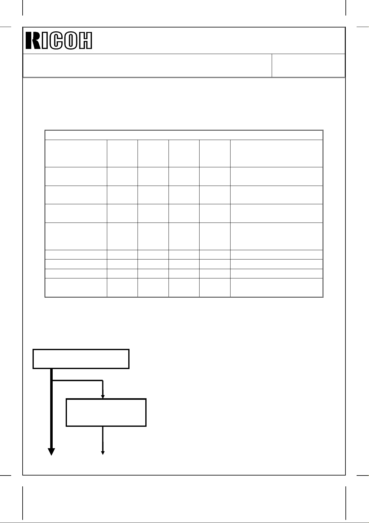
Please correct your service manuals as follows : The part that must be corrected is
underlined.
1. Page 1 - 17
Incorrect
Symbol
Others
CB1 9
CC1 10 Choke Coil Removes high frequency current.
TR1 7
Index
No.
Description Note
Circuit Breaker
(220 ~ 240V
machines only)
Transformer
(220 ~ 240V
machines only)
Revision of service manual
Information only
Other
FROM: 2nd Technical Support Section
MODEL:
Phoenix
(Eagle & Falcon)
Provides back-up high current protection for
electrical components.
Steps down the wall voltage to 100 Vac.
Correct
Symbol
Others
CB1 9
CC1 10
TR1 7
Index
No.
Description Note
Circuit Breaker
(220 ~ 240V
machines only)
Choke Coil
(220 ~ 240V
machines only)
Transformer
(220 ~ 240V
machines only)
Provides back-up high current protection for
electrical components.
Removes high frequency current.
Steps down the wall voltage to 100 Vac.
Page 4
REVISED ON AUGUST 31, ’95
Correct
Technical Bulletin No. RTB-002
SUBJECT: Service Manual Correction DATE: June 15, ’95
PAGE: 2 of 6
2. Page 2 - 5
Incorrect
- ADS Pattern Detection and ADS Correction -
If the user selects Auto Image Density (ADS) mode, the machine
monitors the output from the ADS sensor and adjusts the
development bias to compensate for variations in ADS sensor
response. This prevents dirty background.
Every 1,000 copies, the machine calibrates the ADS sensor output by
reading the ADS pattern under the left scale of the exposure glass.
The ADS sensor must also be recalibrated:
• If the drum is changed
• If the ID sensor is cleaned or changed
• If the exposure lamp or optics are cleaned or changed.
- ADS Pattern Detection and ADS Correction -
If the user selects Auto Image Density (ADS) mode, the machine
monitors the output from the ADS sensor and adjusts the
development bias to compensate for variations in ADS sensor
response. This prevents dirty background.
Every 1,000 copies, the machine calibrates the ADS sensor output by
reading the ADS pattern under the left scale of the exposure glass.
The ADS sensor must also be recalibrated:
• If the drum is changed
• If the ADS sensor is cleaned or changed
• If the exposure lamp or optics are cleaned or changed.
Page 5
REVISED ON AUGUST 31, ’95
Technical Bulletin No. RTB-002
SUBJECT: Service Manual Correction DATE: June 15, ’95
PAGE: 3 of 6
3. Page 3 - 1
Incorrect
Correct
1.1 ENVIRONMENT
1. Temperature Range: 10° to 30° (50°F to 86°F)
2. Humidity Range: 15% to 90% RH
3. Ambient Illumination: Less Than 1,500 lux (do not expose to
direct sunlight.)
4. Ventilation: Room air should turn over at least 3
times / hour.
1.1 ENVIRONMENT
1. Temperature Range: 10° to 30° (50°F to 86°F)
2. Humidity Range: 15% to 90% RH
3. Ambient Illumination: Less Than 1,500 lux (do not expose to
direct sunlight.)
4. Ventilation: Room air should turn over at least
3
30m / hour / person.
Page 6
REVISED ON AUGUST 31, ’95
Technical Bulletin No. RTB-002
SUBJECT: Service Manual Correction DATE: June 15, ’95
PAGE: 4 of 6
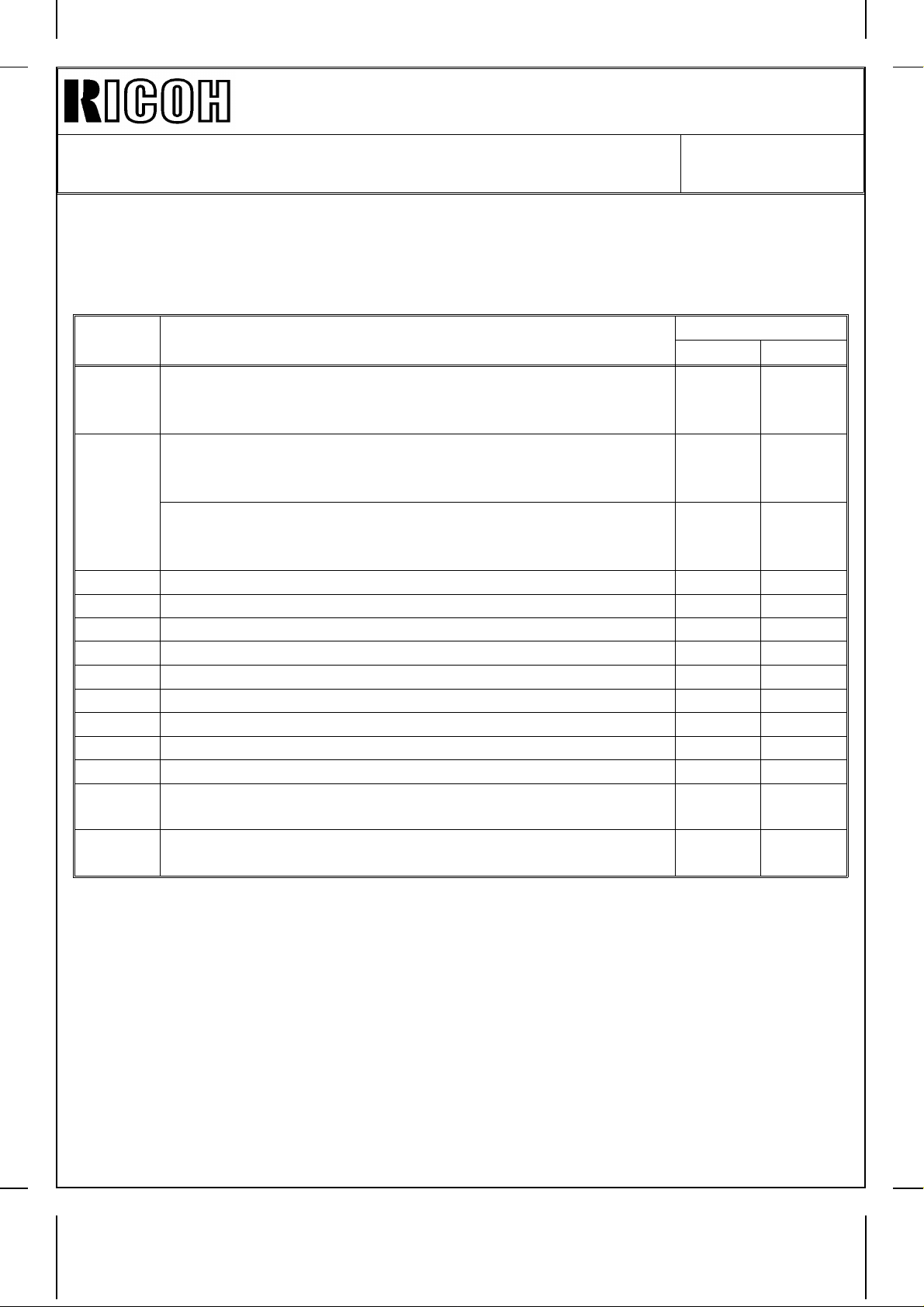
Please correct your service manuals as follows:
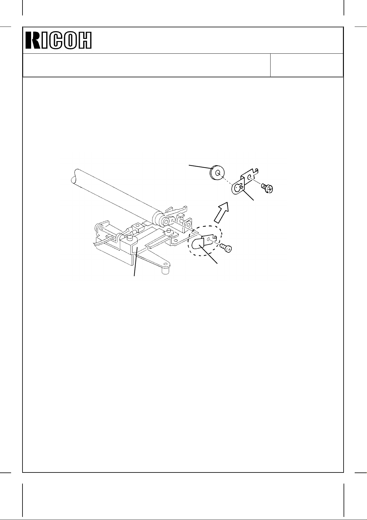
4. Page 5- 27
Please correct the replacement procedures for the Drum Change Roller Terminal as
follows:
4. 10 DRUM CHANGE ROLLER TERMINAL REPLACEMENT
[C]
[B]
[A]
1. Remove the drum charge roller ass’y.
2. Place the drum change roller ass’y [A] on a clean sheet of paper.
3. Remove the drum charge roller terminal [B] (1 screw).
4. Remove the roller terminal [C].
*
NOTE: 1. Never touch the surface of the drum charge roller.
[B]
2. If there is any dirt on the surface of the drum charge roller, wipe it off with a dry
cloth or a special cloth or a special cloth for the drum charge roller.
(The special cloth is available as a service part: A1539004.)
Never use alcohol or water to alean the drum charge roller.
3. When replacing the drum charge roller terminal [B], also replace the roller
*
terminal [C] at the same time.
Page 7
REVISED ON AUGUST 31, ’95
Technical Bulletin No. RTB-002
SUBJECT: Service Manual Correction DATE: June 15, ’95
PAGE: 5 of 6
5. Page 4-54 and page 4-56
Please add the Roller Terminal to the PM table.
AROUND THE DRUM
Drum Charge
Roller R R R
Drum Charge
Roller Cleaner
Drum Charge
Roller Terminal
Roller Terminal
*
ID Sensor
Erase Lamp C C C Dry cloth
Quenching Lamp C C C Dry cloth
Pick-off Pawls C R C Dry cloth
Pre-Transfer
Lamp
RRR
RRR
RRR
CCC
CCC
Clean with the special
cloth if necessary (the
cloth must be dry)
Replace with the drum
charge roller as a set
Replace with the drum
charge roller as a set.
Replace with the drum
charge roller as a set
Blower brush. After
cleaning, do SP3-001
then SP3-1 12
Dry cloth and blower brush
6. Page 4-60
Please add the following procedure to the PM procedure.
3. Around the Drum
(every 100 or 120 k)
Replace the
pick-off pawls
(every 200/240 k).
1. Remove the drum and clean the ID sensor with
a blower brush.
2. Clean the pick-off pawls.
3. Clean the quenching, erase, and pre-transfer
lamps with a dry cloth. Discharge any static
electricity before putting them back.
4. Put back the drum.
5. Replace the drum charge roller, drum charge
roller cleaner, drum charge roller terminal,
and roller terminal.
Page 8
REVISED ON AUGUST 31, ’95
Technical Bulletin No. RTB-002
SUBJECT: Service Manual Correction DATE: June 15, ’95
PAGE: 6 of 6
7. Page 4 - 44
Please add the following items to the SP5 - 803 SENSOR / SWITCH INPUT SIGNAL
DATA CHECK Table.
3rd
level No.
Proof Tray Exit Sensor (A554 Sorter Stapler Only)
* 56
Bin Exit Sensor (A554 Sorter Stapler)
* 57
58 Bi n Sensor (A 554 / A555 ) off on
59 Bin H . P. Sensor off on
60 Bin Lift Timing - 1 Screw (A554) / Wheel Sensor (A555) off on
61 Bin Lift Timing - 2 Sensor (A554 only) off on
63 Jogger H. P. Sensor (A554 / A555) off on
64 Grip H. P. Sensor (A554 / A555) off on
66 Staple H. P. Switch (A554 / A555) off on
67 Staple End Switch (A554 / A555) off on
68 Staple Paper Sensor (A554 / A555) off on
69
70
Sorter Entrance Sensor (A555 Sorter Stapler) Paper
Sorter Stapler Set SW. Front Door SW (A554) /
Door Safety SW. (A555)
Roller Drive Timing Sensor (A554) /
Timing Sensor (A554)
Sensor / Switch / Signal
Reading
01
Paper
detected
Paper
detected
not
detected
Door
Closed
off o n
Paper
not
detected
Paper
not
detected
Paper
detected
Door
Open
* : Revised
Page 9
Technical Bulletin No. RTB-003
SUBJECT: SP-Mode Description Cross Reference Table
(A156 copier only)
PREPARED BY: S. Hizen
CHECKED BY: M. Iwasa
CLASSIFICATION:
Action Required
Troubleshooting
Retrofit Information
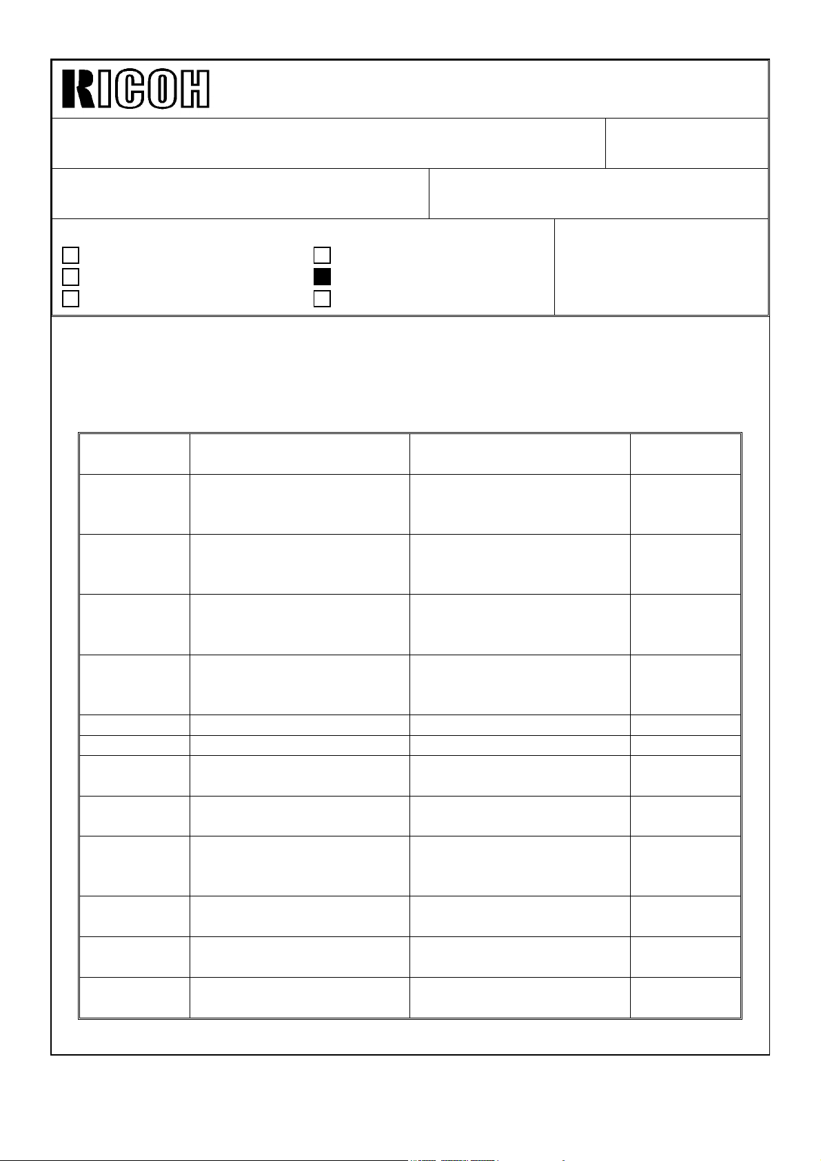
The actual messages displayed on the operation panel LCD would not be good enough for
service engineers to know what mode the machine is set in.
Therefore some description in the SP mode table of the service manual are different from
the messages displayed on the operation panel (A156 copier only) to make it clear what
mode the machine is set in.
The following is the message-description cross reference table of the SP-modes.
SP - No.
1 - 104 Fusing Control
1 - 105 - 001 Fusing Temperature
1 - 105 - 002 Fusing Temperature
1 - 105 - 003 Fusing Temperature
1 - 106 Fusing Temperature check Fusing Temperature Display (5)
1 - 108 Forced start mode Forced Start (5)
2 - 001 Charge voltage adjustment Drum Charge Voltage
2 - 002 Change voltage check Drum Change Voltage
2 - 003 ID sensor pattern charge
2 - 101 - 001 Lead edge erase margin
2 - 101 - 002 Lead edge erase margin
2 - 201 - 001 Development bias voltage
Message Displayed on
LCD
0: on / off 1: Phase
adjustment
adjustment
adjustment
voltage adj.
adjustment
adjustment
adjustment
Revision of service manual
Information only
Other
FROM: 2nd Technical Support Section
MODEL:
Description in Service
Manual
Fusing Temperature Control (5) see page
Fusing Temperature
Adjustment (Main Fusing
Lamp)
Fusing Temperature
Adjustment for Energy
Saver Mode.
Fusing Temperature
Adjustment (Secondary
Fusing Lamp)
Adjustment (for copying)
Display
Drum Charge Voltage
Adjustment (for making V
patterns)
Leading edge erase margin (2)
Trailing edge erase margin (2)
Development Bias
Adjustment (for copying)
DATE: May 15, ’95
PAGE: 1 of 4
Phoenix (A156 copier
only)
Reason for
difference
4/4 for reason
explanation
(2)
(2)
(2)
(4), (5)
(4), (5)
(1), (4), (5)
SP
(2), (5)
Page 10

Technical Bulletin No. RTB-003
SUBJECT: SP-Mode Description Cross Reference Table
(A156 copier only)
SP - No.
Message Displayed on
LCD
2 - 101 - 002 Development bias voltage
adjustment
Description in Service
Lightest ID Level
Development Bias
Adjustment
2 - 203 ID sensor pattern bias
voltage adj.
Development Bias
Adjustment (for making V
Manual
DATE: May 15, ’95
PAGE: 2 of 4
(2), (5) see page
4/4 for reason
explanation
(1), (5)
SP
patterns)
2 - 206 Development bias voltage
Development Bias Display (5)
check
2 - 207 Compulsory toner supply
Forced Toner Supply (3)
mode
2 - 208 - 001 Toner Supply mode
selection
2 - 208 - 002 Toner supply mode selection Toner Supply Ratio
Toner Supply Mode
Selection
(2)
(2), (5)
(TD Sensor Supply Mode)
2 - 208 - 003 Toner supply mode selection Toner Supply Ratio
(2), (5)
(Fixed Supply Mode)
2 - 215 TD sensor output check TD Sensor Output Display (5)
2 - 220 TD sensor initial output
check
2 - 222 Toner supply ratio selection Toner Supply Ratio
TD sensor Initial Output
Display
(5)
(5)
(Detect Supply Mode)
2 - 802 Main charge roller temp.
monitor
2 - 812 Drum reverse amount
adjustment
2 - 901 Main charge cleaning
0:10 1:5 2:2 3:1
3 - 002 VSG confirmation ID Sensor Initial Setting
Drum Charge Roller
Temperature
Drum Reverse Rotation
Adjustment
Drum Change Roller
Cleaning Interval
(4)
(5)
(4), (5)
(5)
Display
3 - 103 VSG / VSP monitor ID Sensor Output Display
3 - 103 - 001 : V
3 - 103 - 002 : V
SP
SG
(5)
3 - 105 VL adjustment Forced VL Detection (1), (5)
3 - 106 Vref (%)
Initial VLP / VLG Display (1), (5)
(Initial Vsl / Vsg)
3 - 107 Vsl / Vsg check Current VLP / VLG Display (1), (5)
3 - 111 Vsr / Vsg check Current V
/ VRG Display (1), (5)
RP
3 - 112 VR adjustment Forced VR Detection (1), (5)
3 - 123 Drum initial setting Drum Initialize (5)
Reason for
difference
Page 11

Technical Bulletin No. RTB-003
SUBJECT: SP-Mode Description Cross Reference Table
(A156 copier only)
SP - No.
3 - 902 Process control data initial
4 - 001 Base exposure lamp voltage Exposure lamp Voltage
4 - 002 Actual exposure lamp
4 - 008 Magnification adj. (vertical) Vertical Magnification
4 - 011 Horizontal registration adj. Lens Horizontal H. P.
4 - 101 Magnification adj.
4 - 201 Auto ADS sensor adjustment Auto ADS Gain Adjustment (1)
4 - 202 ADS sensor setting ADS Initial Gain Display (1), (5)
4 - 203 ADS sensor actual output
5 - 501 - 001 PM interval set PM Interval Setting (2)
5 - 501 - 002 PM interval set PM Interval Setting (PM
5 - 812 TEL: Telephone Number Input (5)
6 - 001 SADF auto reset SADF Auto Reset Time
6 - 009 DF free run DF Free Run with Paper (5)
7 - 401 SC total counter Total Service Call Counter (5)
7 - 402 SC counter SC Counter by Service Call (5)
7 - 502 Total jams by paper size Total Copy Paper Jam
7 - 807 - 001 SC counter clear SC Counter Clear (2)
7 - 807 - 002 SC counter clear Copy Jam Counter Reset (2)
7 - 807 - 003 SC counter clear Original Jam Counter Reset (2)
7 - 811 Original counter clear DF Counter Clear (5)
Message Displayed on
LCD
setting
voltage
(horizontal)
(V)
Description in Service
Manual
Forced Process Control (5)
Adjustment
Exposure Lamp Voltage
Display
Adjustment
Adjustment
Horizontal Magnification
Adjustment
ADS Actual Gain Display (1), (5)
Alarm Mode Setting)
Setting
Counter
DATE: May 15, ’95
PAGE: 3 of 4
Reason for
difference
(5) see page
4/4 for reason
explanation
(5)
(5)
(5)
(5)
(2)
(5)
(3)
NOTE: This cross reference table is only for the SP modes in which messages on LCD
and the descriptions in service manual are different.
Page 12

Technical Bulletin No. RTB-003
SUBJECT: SP-Mode Description Cross Reference Table
(A156 copier only)
Reason
(1) Similar descriptions to the previous model have been adopted for the service manual.
(2) The messages displayed on LCD do not change even though the different 3rd level SP
numbers are selected. Therefore, in the service manual, the correct descriptions are
written for each 3rd level SP numbers.
(3) Translation mistake of message on LCD.
(4) The part names have been changed after the translation of LCD’s message was done.
(5) The SP mode descriptions in service manual explains the actual function of the mode
as much as possible.
DATE: May 15, ’95
PAGE: 4 of 4
Page 13
Technical Bulletin No. RTB-004
SUBJECT: Rubber Plugs for Fiber Cable Connectors DATE: May 15, ’95
PAGE: 1 of 1
PREPARED BY: S. Hizen
CHECKED BY: M. Iwasa
CLASSIFICATION:
Action Required
Troubleshooting
Retrofit Information
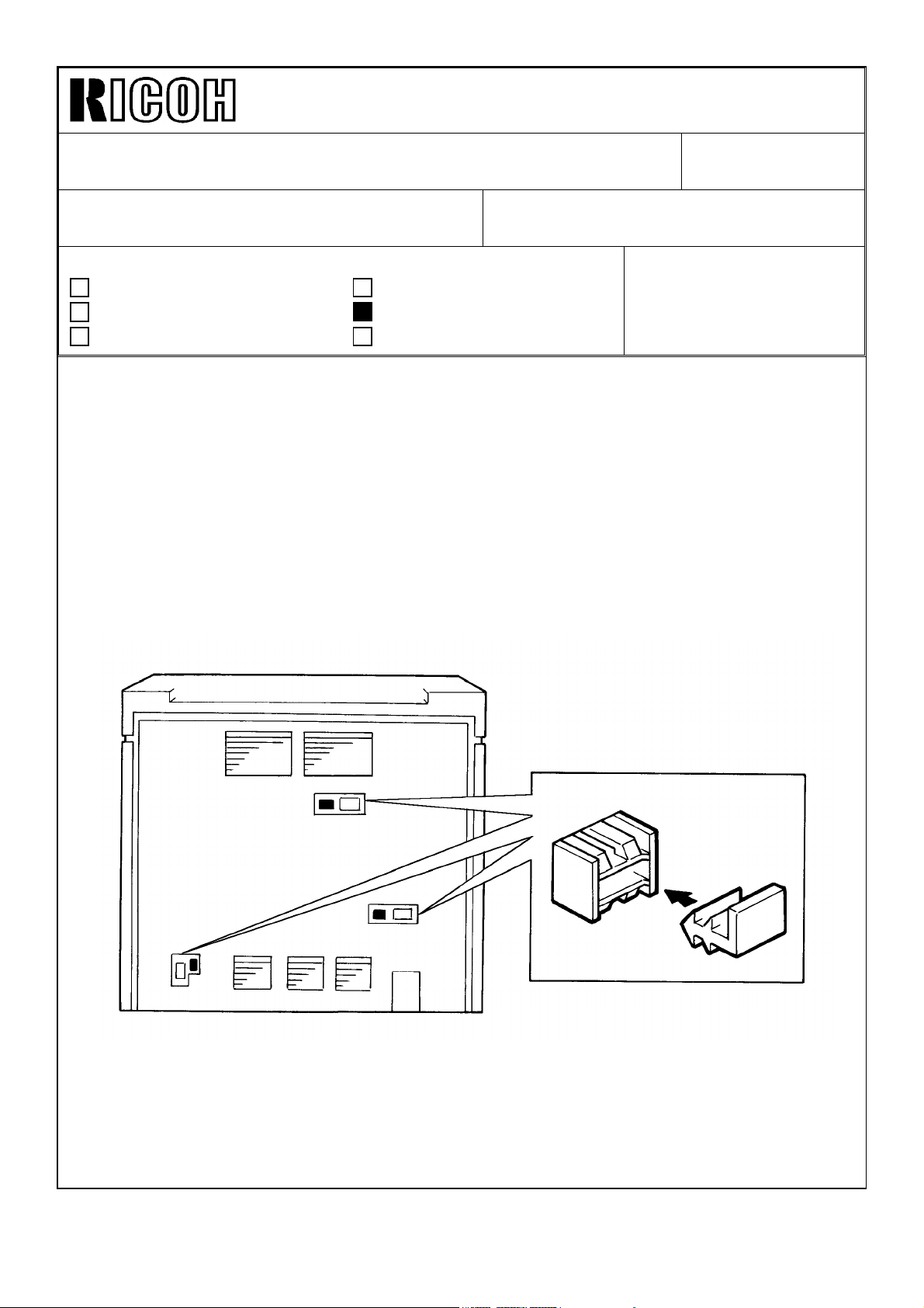
A rubber plug has been added to each fiber optics cable connector to prevent a machine
operation malfunction due to light from outside.
The plug(s) must be removed when a peripheral unit is installed. Please add a plug
removal procedure in the peripheral unit installation procedure of your service manual.
The plugs must be installed when the fiber optics cable connection is not used.
Please instruct your field techs to put the plugs in the unused connectors.
Revision of service manual
Information only
Other
FROM: 2nd Technical Support Section
MODEL:
Phoenix (Eagle, Falcon)
Page 14
Technical Bulletin No. RTB-005
SUBJECT: Energy Star DATE:October 31,
’95
PAGE: 1 of 12
PREPARED BY: S. Hizen
CHECKED BY: M. Iwasa
CLASSIFICATION:
Action Required
Troubleshooting
Retrofit Information
This RTB explains the modifications made to meet the Energy Star requirements.
With this modification, to conserve energy, the copier automatically turns off 60 minutes
after the last copying job has been completed.
The details of the machine operation can be found on pages 3 onward of this RTB.
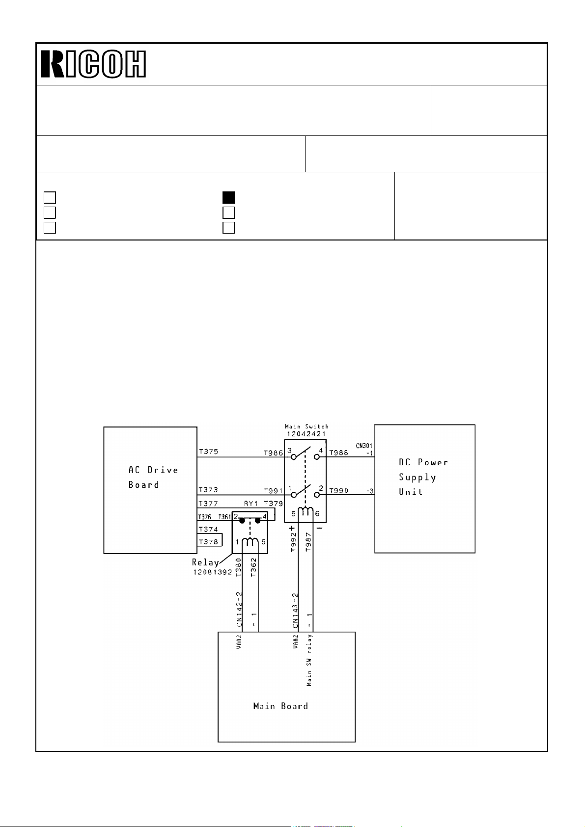
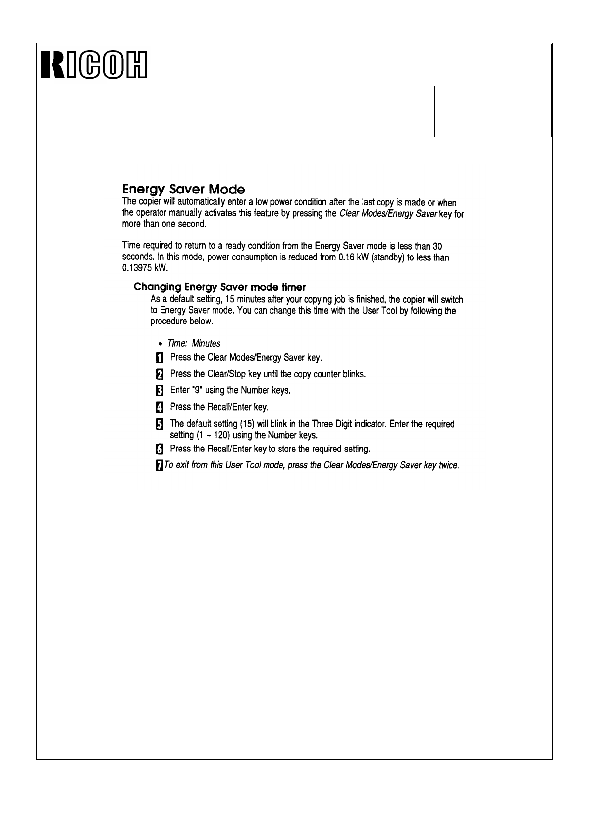
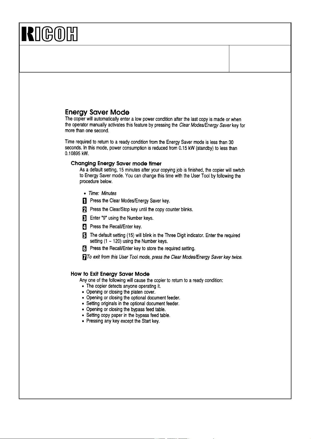
Auto Off Mode
To automatically turn off the copier, a new type of main switch with an incorporated coil is
used. When the CPU drops CN143 - 1 from +24 to 0, the main switch contact is opened.
The wiring diagram and connector layout are shown below.
Revision of service manual
Information only
Other
FROM: 2nd Technical Support Section
MODEL:
Phoenix
(Eagle, Falcon, Swallow)
-10, -15, -17 only
Page 15
Technical Bulletin No. RTB-005
À
Ã
SUBJECT: Energy Star DATE:October 31,
’95
PAGE: 2 of 12
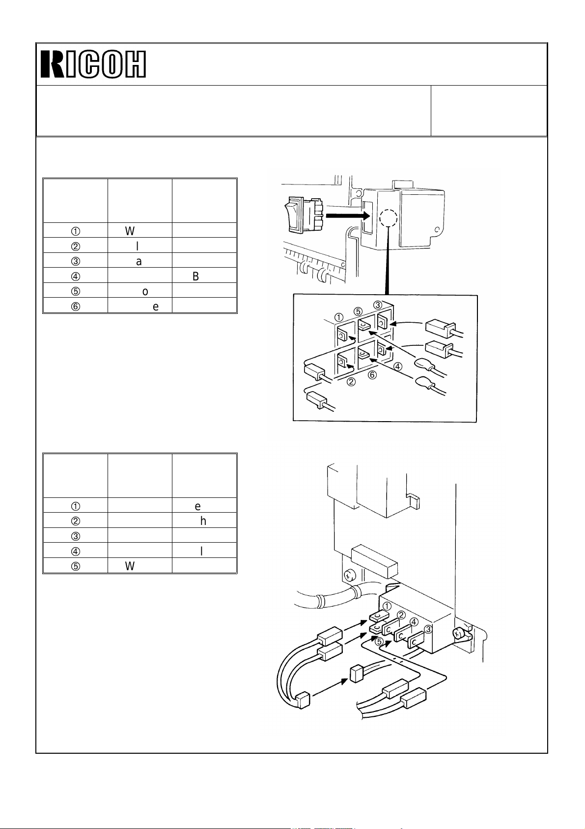
Connector Layout
Main SW
Terminal
No.
À
Á
Â
Ã
Ä
Å
Relay
Terminal
No.
À
Á
Â
Ã
Ä
Wire Color
White Yellow
Blue Blue
Black Yellow
Red Blue
Yellow White
Oranze White
Wire Color
White Yellow
Orange White
——
Black Blue
White Green
Connector
Color
Connector
Color
Á
Ä
Â
Ã
Å
À
Á
Â
Ä
Page 16
Technical Bulletin No. RTB-005
SUBJECT: Energy Star DATE:October 31,
’95
PAGE: 3 of 12
SP Mode
One SP mode has been newly provided and three SP modes have been changed in the
software ( ROM : A153 5106A).
Mode No. Function Settings
SP5-911
SP5-102
SP5-305
Copy mode when machine is turned
on can be selected.
(A156, A160, A162 copiers)
Auto energy saver time can be
selected.
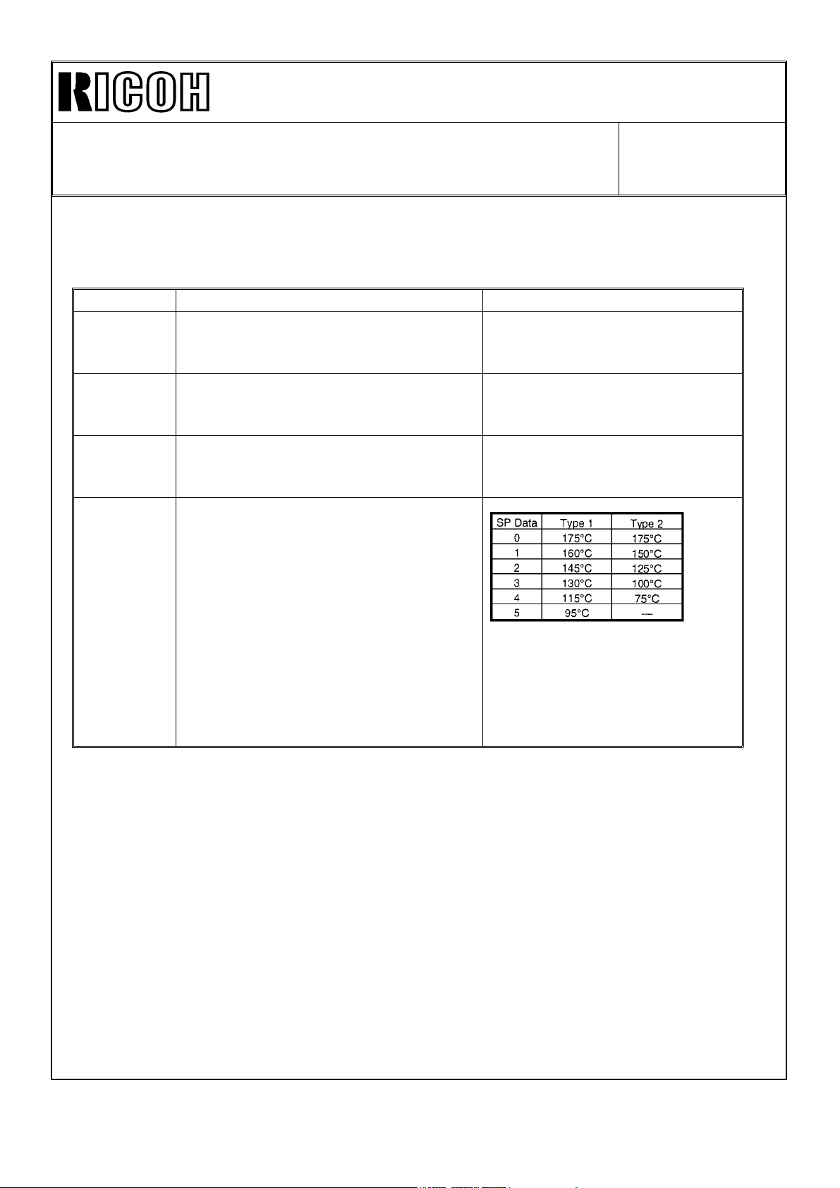
Auto off time can be selected. 1 ~ 120 minutes
Fusing temperature can be selected in
energy saver mode.
1 : Duplex Copy Mode (Default)
2 : Single Side Copy Mode
1 ~ 120 minutes
(1 minute per step)
Default : 15 minutes
(1 minute per step)
Default : 60 minutes
SP5-105-002
Default
2: (145°C) : Eagle
2: (125°C) : Falcon
3: (100°C) : Swallow
SP5-102 and SP5-305 can also be selected by the customer.
Please refer to page (P3 ~ P5 : Eagle, P6 ~ P8 : Falcon, P9 ~ P11 : Swallow) of this
RTB for the procedure.
Instruction Sheet
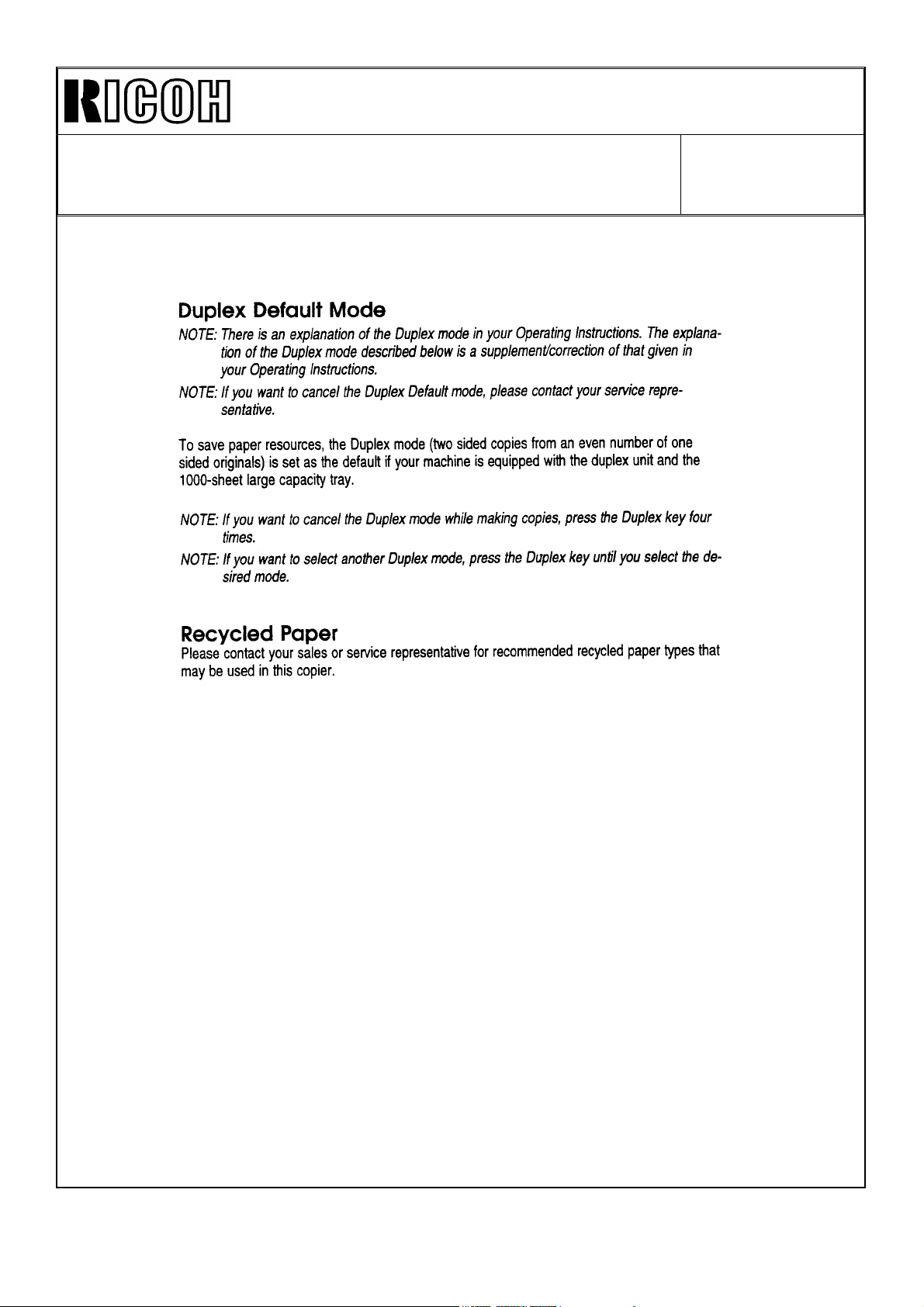
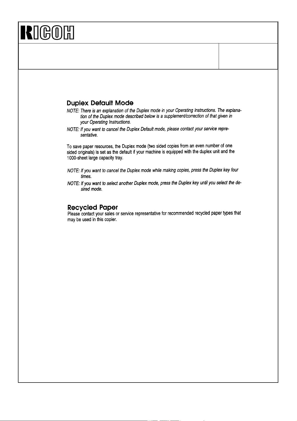
An additional explanation sheet has been added to the operating instructions sheet.
Please refer to pages 3 through 11 of this RTB for the contents of this sheet. The Energy
Saver Mode described on the second page of this instruction sheet is the Auto Energy
Saver Mode originally available with this copier.
Page 17

Technical Bulletin No. RTB-005
SUBJECT: Energy Star
(Eagle O/I)
DATE:October 31,
’95
PAGE: 4 of 12
Page 18
Technical Bulletin No. RTB-005
SUBJECT: Energy Star
(Eagle O/I)
DATE:October 31,
’95
PAGE: 5 of 12
Page 19
Technical Bulletin No. RTB-005
SUBJECT: Energy Star
(Eagle O/I)
DATE:October 31,
’95
PAGE: 6 of 12
Page 20

Technical Bulletin No. RTB-005
SUBJECT: Energy Star
(Falcon O/I)
DATE:October 31,
’95
PAGE: 7 of 12
Page 21
Technical Bulletin No. RTB-005
SUBJECT: Energy Star
(Falcon O/I)
DATE:October 31,
’95
PAGE: 8 of 12
Page 22
Technical Bulletin No. RTB-005
SUBJECT: Energy Star
(Falcon O/I)
DATE:October 31,
’95
PAGE: 9 of 12
Page 23

Technical Bulletin No. RTB-005
SUBJECT: Energy Star
(Swallow O/I)
DATE:October 31,
’95
PAGE: 10 of 12
Page 24

Technical Bulletin No. RTB-005
SUBJECT: Energy Star
(Swallow O/I)
DATE:October 31,
’95
PAGE: 11 of 12
Page 25

Technical Bulletin No. RTB-005
SUBJECT: Energy Star
(Swallow O/I)
DATE:October 31,
’95
PAGE: 12 of 12
Page 26

Technical Bulletin No. RTB-006
SUBJECT: • Continuous Supply of power to the Jogger Motor
• Developer Leakage
PREPARED BY: S. Hizen
FROM: 1st Field Information Dept. QAC
DATE: May 15, ’96
PAGE: 1 of 4
CHECKED BY:
CLASSIFICATION:
Action Required
Troubleshooting
Retrofit Information
Revision of service manual
Information only
Other
MODEL:
Continuous Supply of power to the Jogger Motor
1. Phenomeno n:
The Jogger Motor is continuously supplied with power but does not rotate which
leads to the deformation of the mold around the duplex unit. SC525 may be
indicated for the Duplex Copy Mode because the Jogger Motor is not rotating. A
continuous supply of power will result in overheating of the Jogger Motor.
2. Possible Causes:
When the Jogger Motor is operating, if there is a drop in voltage of 5v, the ISP may
malfunction, and as a result two phases of the motor will continue to be supplied
with power.
Phoenix
Main Board
ISPCPUPSU
DRIVER
M
3. Countermeasure and Field Action :
We will change the software so that the Jogger Motor power will automatically shut
off if any of the phases of the motor runs continuously for 3 minutes or longer. The
ROM part number with this program is A153-5109. If this problem occurs, the
stepping motor part of the duplex tray may be deformed by the heat generated. We
would appreciate it if you would replace the whole duplex tray and also install the
ROM A153-5109 at that time.
Additional Information: The implementation of the modified ROM is planned for the
middle of July for the mass-production units. We would like to emphasize that the
occurrence ratio of this problem is very low.
24V
Page 27

Technical Bulletin No. RTB-006
SUBJECT: • Continuous Supply of power to the Jogger Motor
• Developer Leakage
Developer Leakage
1. Problem:
The main motor, charge roller, transfer belt and development unit are continuously
in the ON condition. This results in developer leakage from the development unit
and ultimately leads to blank copies because of a shortage of developer.
h In this case, the leaked developer accumulates in the transfer unit. Accumulation
in the rear of the development unit may indicate wear on the paddle roller shaft
caused by developer as a result of the improper placement of the V-ring, and could
necessitate replacement of the unit. There have only been a few isolated cases
reported worldwide connected with the V-ring placement and we do not anticipate
more occurrences.
2. Conditions leading to the Occurrence:
This problem may occur when the timing of the Pre-start signal and the ADS
Density signal are sent at approximately the same time when the machine is set in
the following conditions: ADS Mode, Special Paper Feed Tray (see the attached
table for details), Special CPM (see the attached table for details), 1st copy after
start-up (Including the 1st copy after the completion of the second feed in the duplex
mode), or when the copy count is 1 to N.
DATE: May 15, ’96
PAGE: 2 of 4
3. Cause:
The Pre-Start signal for the software’s engine control area is erased by the ADS
Density signal.
Normal:
ADS Density signal sent signal received ADS Density signal processed
PreStart signal sent signal received PreStart signal processed
Abnormal:
PreStart signal sent signal received ADS signal sent
signal received ADS signal processed.
h In this case, the final processing of the PreStart signal is not completed. The
control based on the image trailing edge signal of the engine control area stops
working properly and as a result the main motor, charge roller, transfer belt and
development unit remain ON.
4. Countermeasure:
We will change the software by inserting a signal processing function prior to the
signal receipt that is activated when the ADS Density signal is sent. As a result, the
abnormal signal route will be changed in the following manner.
PreStart signal sent signal received ADS Density signal sent
PreStart signal processed signal received ADS Density signal processed.
The ROM part number is also A153-5109. If this problem occurs, please replace
Page 28

Technical Bulletin No. RTB-006
SUBJECT: • Continuous Supply of power to the Jogger Motor
• Developer Leakage
DATE: May 15, ’96
PAGE: 3 of 4
Page 29

Technical Bulletin No. RTB-006
SUBJECT: • Continuous Supply of power to the Jogger Motor
• Developer Leakage
DATE: May 15, ’96
PAGE: 4 of 4
Page 30

Technical Bulletin No. RTB-007
SUBJECT: Identification of and Measures for Fusing Offset DATE: May 15, ’96
PAGE: 1 of 4
PREPARED BY: S. Hizen
CHECKED BY:
CLASSIFICATION:
Action Required
Troubleshooting
Retrofit Information
Revision of service manual
Information only
Other
FROM: 1st Field Information Dept. QAC
MODEL:
Phoenix
Identification of and Measures for Fusing Offset
By employing the proper procedures in the field, the Offset problems reported there
may be prevented. When an offset problem occurs, it is very important to correctly
isolate the cause and utilize proper measures to solve the problem. Hence, we have
compiled a list of the types of offset often encountered in the field, methods to
identify the offset and measures to be taken. This list is arranged in the following
manner: A. Offset problems related to Fusing B. Phenomena mistaken for Offset.
Each symptom presented lists causes and the measures to be taken.
A. Cases of Offset related to Fusing
1. Hot Offset (excessive fusing)
After consecutive paper feeds, periodic offsets occur (125mm pitch). Similar
problems are sometimes found when using comparatively thin paper.
Cause/Measure:
• Check the fusing temperature. Is it set too high? The maximum is 190°C.
• Is the thermistor coming in contact with the roller? Confirm that the roller comes
in firm contact with the thermistor. Check for deformation of the thermistor unit.
• Is the thickness of the paper within specifications? Standards 52~157g/m2,
14~42lbs.
h
Confirm the implementation of the anti-rise countermeasure for the thermistor.
Anti-rise countermeasure
Metal Bracket Plastic Bracket
Thermistor Thermistor
Page 31

Technical Bulletin No. RTB-007
SUBJECT: Identification of and Measures for Fusing Offset DATE: May 15, ’96
PAGE: 2 of 4
2. Cold Offset (incomplete fusing)
Offset (125mm pitch) only occurs in the morning when the machine is first turned on
or when using thick paper.
Cause/Measure:
• Low temperature environment? In conditions under 10°C and 15% humidity, prob-
lems may occur when the machine is turned on at the beginning of the day.
• Is the temperature adjusted to the proper setting? Is it set too low? The minimum is
160°C.
• Has there been a drop in voltage? Is it below 90v? In this case, the nip area should
be increased and the temperature setting should be raised.
3. Electrostatic Offset
When using OHPs or laminated paper, offsets appear scattered around the
characters.
Cause/Measure:
• Are the fusing roller and pressure roller properly grounded? Make sure that the
quenching brush on the back of the rollers is touching both the fusing and pressure
rollers.
• Is the fusing entrance guide board properly grounded? Make sure that the quenching
brush behind the unit fusing stay and the fusing entrance guide are connected when
the fusing unit is in place.
• What is the environment like? In conditions below 10°C and 15% humidity, certain
types of paper are prone to electrostatic offset.
Though certain types of paper may be subject to this condition, occurrences are quite
rare so this should not occur under normal operating conditions.
illustration from P/C P46
This brush should
contact both the
Hot and Pressure
Rollers.
Page 32

Technical Bulletin No. RTB-007
SUBJECT: Identification of and Measures for Fusing Offset DATE: May 15, ’96
PAGE: 3 of 4
4. Insufficient Cleaning Offset
Irregular occurrences, falls off when wiped by hand. Occurs over the whole surface,
large amounts involved.
• Inadequate cleaning of the pressure roller leads to residue on the pressure roller. This
reduces the lifetime of the pressure roller, and premature replacement is necessary.
• Is the cleaning roller attached?
• Is the cleaning roller rotating properly?
• Is there an uneven build up of toner?
If any of these symptoms apply, replace the cleaning roller. However, if there is
toner accumulation of about 0.5mm near the cleaning roller, the cleaning efficiency
has dropped and indicates that the roller should be replaced. If the accumulation is
less than 0.5 mm, then the chances that this roller is the cause of the problem are
very slight.
5. A narrow horizontal black line, not on the original, appears on the copy 125mm from
the front edge or it continues at a 125mm pitch.
Cause:
No blank areas on the leading and/or trailing edges.
Measure:
Blank areas should be created at both the leading and trailing edges. (This only
occurs when the blank areas are 0mm)
6. The offset picture and characters are inverted. (When using the back of the sheet, the
image aligns with the one on the other side.)
Cause:
The melting point of the toner of the image on the back of the sheet is too low.
Measure:
If the melting point of the toner is too low, stop the use of the back of the sheets.
Examples of toners with low melting points: Flash fusing , color copier,
hot transfer ribbons.
7. Irregular occurrences, falls off when wiped by hand. Related to the position of the
thermistor.
Cause/Measure:
• Toner debris accumulated on the thermistor. Caused by a dirty thermistor. Clean the
thermistor.
Page 33

Technical Bulletin No. RTB-007
SUBJECT: Identification of and Measures for Fusing Offset DATE: May 15, ’96
PAGE: 4 of 4
8. Frequent Offset; Toner accumulation on the fusing roller Cause/Measure:
Conditions 1~7 listed above did not continue?
• Abnormal Image Condition (drop in density, defective drum cleaning, defective transfer cleaning, etc.) did not continue?
• Was the total number of copies made while the machine was in use extremely high
or low?
• Is the toner a Ricoh product?
• Is the fusing roller a Ricoh product?
• Is the pressure roller a Ricoh product?
h
Some types of paper may be the cause of the problem when offset continues on
some machines. Please contact us if this is the case.
B. Phenomena mistaken for Offset
1. The offset drawings and characters are inverted (Aligned with the image on the back
of the original)
Cause: The back of the original was copied.
2. The offset pitch is 188.5mm
Cause: Scratched drum Replace the drum
3. Irregular Occurrences, Fused Image
Cause: Defective drum cleaning Confirm that the parts around the drum are
functioning properly (cleaning blade, etc.)
4. Images on the surface unrelated to the original, lines appear parallel to the paper
feed direction.
Cause: Defective drum cleaning, scratched drum, uneven lighting from the exposure
lamp Inspect the parts around the drum (cleaning blade, etc.) Check for uneven
lighting level
5. Lines appear on the back of the copy parallel to the paper feed direction.
Cause: Defective transfer belt cleaning, toner scattering in the machine
Check the transfer unit, cleaning blade. Toner scattering may occur because the
toner density is too high, so the Process Control Conditions should be checked.
Page 34

Technical Bulletin No. RTB-008
SUBJECT: ROM History from A153-5106 to A153-5109 DATE: May 15, ’96
PAGE: 1 of 1
PREPARED BY: S. Hizen
CHECKED BY:
CLASSIFICATION:
Action Required
Troubleshooting
Retrofit Information
The following is the software program history describing the changes made from
A153-5106 to the A153-5109.
1. A153-5106 to A153-5107
The transfer bias will automatically shut off when the main motor shuts off. This is
the countermeasure for the drum spot problem that occurs as a result of an
electrical leak from the transfer belt to the drum surface. .This modification will also
take care of the report from the market which stated that the transfer bias remained
on even though the machine was on stand-by.
h
Note: A153-5107 to 5107A-Software change for the ADS Control A slightly dirty
background appears a couple of millimeters from the trailing edge only if
a dark original is copied and the machine is in the ADS mode.
Revision of service manual
Information only
Other
FROM: 1st Field Information Dept. QAC
MODEL:
Phoenix
2. A153-5107 to A153-5109
• Continuous Supply of Power to the Jogger Motor
• Developer Leakage
Please refer to RTB-006 for details.
Additional Information:
The implementation of the modified ROM # A153-5109 is planned for the middle of
July for the mass-production units. We would like to emphasize that the occurrence
ratio of this problem is very low.
Page 35

Technical Bulletin No. RTB-009
SUBJECT: Service Manual Correction DATE: May 15, ’96
PAGE: 1 of 1
PREPARED BY: S. Hizen
CHECKED BY:
CLASSIFICATION:
Action Required
Troubleshooting
Retrofit Information
Please correct your service manuals as follows:
Page 4-28
Incorrect:
5-003 APS Priority
Selection
5-004 ADS Priority
Selection
=
=
Revision of service manual
Information only
Other
Specifies whether the copier
defaults to APS or manual mode
when the main switch is turned on,
auto reset, or mode cleared.
Specifies whether the copier
defaults to ADS or manual ID mode
when the main switch is turned on,
auto reset, or mode cleared.
FROM: 1st Field Information Dept. QAC
MODEL:
Phoenix
1: APS
2. Manual
Also see
SP6-010.
1: ADS
2. Manual
Correct:
5-003 APS Priority
Selection
5-004 ADS Priority
Selection
=
=
Specifies whether the copier
defaults to APS or manual mode
when the main switch is turned on,
auto reset, or mode cleared.
Specifies whether the copier
defaults to ADS or manual ID mode
when the main switch is turned on,
auto reset, or mode cleared.
1: APS
0: Manual
Also see
SP6-010.
1: ADS
0: Manual
Page 36

Technical Bulletin No. RTB-010
SUBJECT: White Lines/Bands due to a dirty charge roller DATE: July 15, ’96
PAGE: 1 of 1
PREPARED BY: S. Hizen
CHECKED BY:
CLASSIFICATION:
Action Required
Troubleshooting
Retrofit Information
Phenomenon:
White lines/bands appear on the copy image. In almost all of these cases, the image
density is low in the lines/bands, so these areas are not as dark.
CHARGE ROLLER
CLEANING PAD
CLEANING
BLADE
DRUM
Revision of service manual
Information only
Other
Cause/Mechanism:
The amount of electrical charge on the drum is
low due to toner accumulation on the charge
roller. This decreases the charge ability. The
toner remains on the drum after it passes under
the cleaning blade and adheres to the charge
roller. The amount of toner remaining on the
drum exceeds the amount that can be cleaned
off by the charge roller cleaning pad, leading to
toner accumulation on the charge roller. The
toner accumulation level on the charge roller is
directly related to the cleaning ability of the
cleaning blade. As a result of the accumulation,
the charge ability decreases due to the toner
accumulation and leads to the white (lighter)
lines/bands on the copy.
FROM: 1st Field Information Dept. QAC
MODEL:
Phoenix
Countermeasure:
In addition to cleaning the charge roller, please check the cleaning blade. If no
defective/deteriorated areas can be found on the blade, please replace it.
Page 37

Technical Bulletin No. RTB-011
SUBJECT: DF61 Dirty Mark on Back-side of Original DATE:July 31, ’96
PAGE: 1 of 3
PREPARED BY: S. Hizen
FROM: 1st Field Information Dept. QAC
CHECKED BY:
CLASSIFICATION:
Action Required
Troubleshooting
Retrofit Information
Revision of service manual
Information only
Other
MODEL:
Phoenix-series
(DF61)
Problem: Three dirty marks on the back side of the original.
Cause: The toner on the first original is transferred to the back of the second
original due to the pressure applied by the pressure lever and the pick-up roller.
(See the illustration)
Pressure Lever
Second
Original
First Original
Pick-up Roller
Pick-up Roller
The dirty marks created are one of the limitations of the DF61. The degree to which
the marks appear varies depending on how completely the image on the first original
is fused, the type of image, and the type of paper used.
Countermeasure:
Due to this countermeasure for the DF61, the specifications listed in the service
manual have been changed as follows:
Specification Item Current DF Modified DF
Original Weight 52 to 128 g/m
2
Original Table Capacity 50 sheets at 80 g/m
2
35 sheets at 80 g/m
52 to 104 g/m
2
2
Page 38

Technical Bulletin No. RTB-011
SUBJECT: DF61 Dirty Mark on Back-side of Original DATE: July 31, ’96
PAGE: 2 of 3
The countermeasure for the dirty marks is designed to reduce the pressure applied
to the originals by replacing the entrance guide stopper spring with a new one. This
change also results in a decrease in the amount of force used to feed the original
and may create an original non-feed problem. Therefore, the separation bracket
has been modified to reduce the angle by 2 degrees.
Separation Bracket
Separation Bracket
2°
CURRENT
Modification Procedure:
1. Remove the three springs from the entrance guide stopper and install the new
spring (P/N:A548 9500) in the middle. If an original non-feed occurs, add the
outside springs (P/N:A548 9500) on both sides.
MODIFIED
Remove the spring
Remove the spring
Replace the spring with a
new one (weaker).
70g (current) → 40g (new)
Page 39

Technical Bulletin No. RTB-011
SUBJECT: DF61 Dirty Mark on Back-side of Original DATE: July 31, ’96
PAGE: 3 of 3
2. Remove the DF separation bracket. (1 snap ring)
3. Replace the separation bracket with A548 9502.
Plastic Plate
Mylar
Plastic
Plate
A548 1291
Current Type
4. Reassemble the parts.
Note: The spring (A548 9500), and the bracket (A548 9502) are available as
spare parts.
A548 9502
Modified Type
Mylar
Page 40

Technical Bulletin No. RTB-012
SUBJECT: Black lines caused by the development entrance seals DATE: Sept. 30, ’96
PAGE: 1 of 3
PREPARED BY: S. Hizen
FROM: QAC 1st Field Information Dept.
CHECKED BY:
CLASSIFICATION:
Action Required
Troubleshooting
Retrofit Information
Revision of service manual
Information only
Other
MODEL:
Problem: Black lines due to scratches on the drum.
Possible Causes: One of the possible causes of the drum scratches may be the
entrance seals on the development unit. There are two manners
in which scratches may appear on the drum.
1)
Foreign
Material
[A]
DEVELOPER
.
DRUM
DEVELOPMENT
ROLLER
The outside entrance seal [A] bends
into a Z shape. The drum may be
scratched when foreign material
gets caught between the drum and
the seal [A].
Measure: Replace the seal [A].
(Please refer to the following page
for the position in which the seal
should be applied.)
Phoenix
2)
Foreign
Material
[A]
When the inside entrance seal [B]
is longer than the outside one, if
Outside
Entrance
Seal [A]
OK
[B]
.
[B]
Inside
Entrance
Seal
Inside
Entrance
Seal
foreign material gets caught
between the drum and the outside
entrance seal [A], the drum may
be scratched due to the pressure
created by the developer. Please
check the lengths of the seals.
(Developer tends to stick on the
upper portion of the development
roller if the inside seal is longer
than the outside one.) If the inside
seal [B] is 1.5 mm or more longer
than the outside one, please
1.5 mm
NG
or
more longer
rotate the development sleeve
counterclockwise to see if any
developer falls from the upper
portion of the roller.
If some developer falls off, you
should replace the inside seal [B].
Please refer to the following page
for the position in which the seal
should be applied.
Page 41

Technical Bulletin No. RTB-012
SUBJECT: Black lines caused by the development entrance seals DATE: Sept. 30, ’96
PAGE: 2 of 3
The seal positions are as follows.
Be sure to first clean the areas where the seals will be attached.
Align the edge of the seal with the
edge of the bracket.
A
AA15 2333
AA15 2334
A
Align the edge of the seal with the edge of the bracket.
Position of the #2, #20 seals
0 ~ 1mm
#20
AA15 0231
A
#2: AA15 0382
#2
AA15 0382
Page 42

Technical Bulletin No. RTB-012
SUBJECT: Black lines caused by the development entrance seals DATE: Sept. 30, ’96
PAGE: 3 of 3
We have assigned a part number for the Entrance Seal Ass’y shown in the illustration to
make the replacement of the seals easier.
* Please refer to page 2 of 3 for the positions of the seals #2, #20
A153 3075
20
Page 43

REVISED ON OCTOBER 31, ’96
Technical Bulletin No. RTB-013
SUBJECT: Dirty Background DATE: Oct. 15, ’96
PAGE: 1 of 2
PREPARED BY: S. Hizen
CHECKED BY:
CLASSIFICATION:
Action Required
Troubleshooting
Retrofit Information
The countermeasure for the dirty background is as follows. This countermeasure is for
those machines that are installed in places with a lot of dust and have had many
service calls related to dirty background. Be sure that you check the optics cavity
because an external examination of the machine may be deceptive.
Possible Causes:
1. Low copy volume machines
The lamp voltage correction/compensation by the process control every 1K copies
cannot catch up with the lamp voltage level necessary to eliminate the dirty
background.
2. High copy volume machines
The lamp voltage increases to the maximum level, and the voltage cannot rise high
enough to create the light intensity necessary to eliminate the dirty background.
Revision of service manual
Information only
Other
FROM: 1st Field Information Dept. QAC
MODEL:
Phoenix (Eagle, Falcon)
Countermeasure:
1. ROM (P/N: A153-5120) The process control interval can be changed with SP Mode
3-801 to suit the environmental conditions in which the copier is installed. The
adjustment levels are as follows.
New Program (A153-5120)
SP3-801
0: OFF
1: Process Control Cycle every 1K copies (Default)
2: Process Control Cycle every 500 copies
3: Process Control Cycle every 200 copies
Page 44

REVISED ON OCTOBER 31, ’96
Technical Bulletin No. RTB-013
SUBJECT: Dirty Background DATE: Oct. 15, ’96
PAGE: 2 of 2
2. Optics Filter (P/N: A153-9515, Left/Right filter set)
Optics Filters will be assigned as service parts. (The mass-production unit does not
have these filters on the optics cavity.) This filter is designed to prevent the optics
cavity from becoming dusty. The positions in which the filters should be placed are
shown below.
Upper Cover
Filter Installation Procedure:
• Remove the upper cover
• Install both the left and right filters so that the holes in the filters are aligned with
the holes in the optics frame.
Optics Filter (Left)
Optics Filter (Right)
The optics filter will not be available as a service part until after the MB has been
issued.
Note: Do not put the filters on those Phoenix machines that usually make copies
continuously under the following conditions:
Eagle: More than 500 copies
Falcon/Swallow: More than 600 copies
If you install the optics filters on a machine which the customer may make
continuous runs which exceed the conditions set above, please set the
copy limit with SP5-017 to the maximum numbers. This is because the
temperature of the exposure glass may be much higher if the lamp voltage
has already reached the maximum level to compensate for the image
density
3. Exposure Lamp
In dusty environments, the exposure lamp should be cleaned at the same time
as the mirror and lens. If there is no improvement, please replace the
exposure lamp.
Page 45

Technical Bulletin No. RTB-014
SUBJECT: Bits of glue on the drum DATE:Oct. 31, ’96
PAGE:1 of 3
REPARED BY: S. Hizen
CHECKED BY:
CLASSIFICATION:
Action Required
Troubleshooting
Retrofit Information
Problem:
The drum becomes dirty with glue.
Possible Cause:
Glue can be transferred to the drum surface when adhesive paper is used.
Sometimes the glue stuck on the drum surface transfers to the entrance seal on the
development unit when the drum rotates in reverse. This results in the deformation of
the entrance seal on the development unit.
Countermeasure:
A mylar has been added on the upper transfer entrance guide, and the transfer guide
plate has been modified by raising the height of its ribs to alter the angle in which the
paper enters. See the illustrations below.
Revision of service manual
Information only
Other
FROM: QAC 1st Field Information Dept.
MODEL: Phoenix
A153 3899
Transfer
Guide Plate
OLD
Mylar A153 3591
A153 3901
Transfer
Guide Plate
NEW
Page 46

Technical Bulletin No. RTB-014
SUBJECT: Bits of glue on the drum DATE: Oct. 31, ’96
PAGE: 2 of 3
Technical Information
The mylar position is as follows. Turn the drum unit over and put a mylar
(A153-3591) in the position shown below.
C3
Front
A : 0 ~ 0.5 mm
B : 0 ~ 2 mm
Upper Guide
Make sure that the duplex adhesive tape does not stick out beyond the end of
the upper guide and that the mylar is flat.
Rear
Page 47

Technical Bulletin No. RTB-014
SUBJECT: Bits of glue on the drum DATE: Oct. 31, ’96
PAGE: 3 of 3
NOTE: Another possible cause of the glue on the drum surface is that
the entrance seal of the development unit is set higher than it should
be by a couple of millimeters. In this case the glue also sticks on the
edge of the development unit and the entrance seal is bent.
It is necessary to replace the entrance seals in this case.
Please refer to RTB-012.
The outside entrance
seal is easily flipped.
: NG
: OK
Normal Entrance Seal
position. No flipping.
➁
➀
The entrance seal position is
a little off (1.5 - 2.0 mm).
The first bend in the
seal appears.
➃
The edge of the seal flips
up inside easily.
The glue sticks on the
edge of the seal.
The glue sticks on
the drum surface.
➄
➂
The seal is bent at another
position and creates a Z-shape
Foreign material
sticks on the
glue. This results
in drum scratches.
Page 48

RICOH
RTB Correction
Reissue date:
The items in bold italics have been corrected or added.
Model:
Phoenix Series
23-Mar-98
Date:
28-Feb-97
Technical Bulletin
No:
015
1/1
Subject:
From:
Drum filming with toner
QAC Field Information Dept.
Classification:
Troubleshooting
Mechanical
Paper path
Other ( )
Part information
Electrical
Transmit/receive
Prepared by:
Action required
Service manual revision
Retrofit information
M.Kitajima
SYMPTOM
The drum becomes covered with a black substance, most likely toner, after 8K to 20K copies.
The surface of the drum seems to be coated with toner across a width equal to that of the
paper or the development roller. As a result, dirty background appears all over the copy.
CAUSE
The additives contained in the acid paper called talc (MgO SiO2) cause the filming problem.
Mechanism
The talc characteristics make it negat ively polarized. The talc powder is electrostatically
attracted to the positively polarized toner and adheres to the drum surface in non-image areas.
Once on the drum, the toner/ talc mixture is pressed down by the transfer belt and charge
roller, leading to a gradual build-up on the drum surf ace. The talc on the drum surface is
carried to the development unit and accumulates there. This accumulation of talc accelerates
the filming problem in an area the width of the development roller.
Coated with toner
SOLUTION
Charge the type of paper used from the acid type to a neutral type. The t ype of paper can be
checked in the following manner.
1.
Use the checking pen. (The part number will
2.
Burn a piece of the paper and check the color of the paper ash.
Black ®acid type
Gray/white ®neutral type
NOTE:
to be replaced and the transfer belt needs to be cleaned.
Once this problem occurs, the drum and developer in the development unit need
not
be available.)
Page 49

RICOH Technical Bulletin
Paddle Roller
Bushing
MB Correction
Reissue date: 31-Mar-97
The items in bold italic have been corrected or added.
The illustrations have been changed as shown below.
Model: Phoenix Series Date: 28-Feb-97
Subject: Paddle Roller Bushing worn out Prepared by: S. Hizen
From: QAC 1st Field Information Dept. Checked by: T. Inoue
Classification:
Troubleshooting
Mechanical
Paper path
Other ( )
Part information
Electrical
Transmit/receive
No: 016
Action required
Service manual revision
Retrofit information
SYMPTOM
Developer leakage from the paddle roller bushing in the development unit.
CAUSE
The V-ring on the paddle roller is out of position.
[OK] [NG]
V-ring V-ring
1/4
V-ring
touches
the plate
Metal
Plate
Developer leakage
SOLUTION
Replace the bushings and V-rings on the paddle roller.
Please refer to the following pages for the replacement procedures.
Page 50

RICOH Technical Bulletin
Model: Phoenix Series Date: 28-Feb-97 No: 016 2/4
[Paddle roller replacement procedure]
1. Remove the toner hopper from the development unit.
2. Remove the three seals (AA15-0382) [A] and the one seal (AA15-0231) [B] from the
development unit.
Entrance Seal Ass’y[C]
Screw[D]
Seal [B]
Seal [A]
Side Bracket[E]
Screw [F]
3. Remove the entrance seal assembly (A153-3075) [C]
(2 screws [D])
4. Remove the side bracket [E] (2 screws: [F])
Page 51

RICOH Technical Bulletin
Paddle Roller
Bushing
Model: Phoenix Series Date: 28-Feb-97 No: 016 3/4
Screw[G]
Do not loosen this screw
[H]
[J]
[K]
[I]
[J]
[K]
5. Separate the Upper and Lower Unit (3 screws [G], 1 screw [H])
6. Remove the paddle roller ass’y [I]: A153-3063 and replace the bushings [J]: AA08-
0200 and V-rings [K] AA15-2331.
Note 1: Make sure that the V-ring is in the proper position, as shown in the illustration
below.
V-ring V-ring
V-ring
touches
the plate
Developer leakage
Metal
Plate
Good No Good
Page 52

RICOH Technical Bulletin
Model: Phoenix Series Date: 28-Feb-97 No: 016 4/4
Note 2: If the shaft of the paddle roller is worn out, replace the entire paddle roller
assembly (A153-3063) [I].
7. Reattach the Upper and Lower Units.
8. Reattach the side bracket.
9. Reattach the entrance seal ass’y and the seals.
Page 53

RICOH Technical Bulletin PAGE: 1/1
Model: Phoenix series Date: 30-Apr-97
No: 17
Subject: SC condition due to electrical arcing Prepared by: S.Hizen
From: QAC 1st Field Information Dept. Checked by: T. Inoue
Classification:
Troubleshooting
Mechanical
Paper path
Other ( )
Part information
Electrical
Transmit/receive
Action required
Service manual revision
Retrofit information
SYMPTOM
A service call condition may occur in the repeat copy mode. A blank copy with a slightly
dirty background may be made in this SC condition. The possible service codes are
SC302, 346, 354, 544, 547.
POSSIBLE CAUSE
The ground brush does not come in contact with the rollers because the bracket of the
brush is deformed or the brush itself is bent.
A static electrical charge accumulates on the guide plate or the rollers when repeat copies
are made if the ground brush does not contact these parts. An electrical arc occurs when
the amount of the static electrical charge reaches a threshold level and this arcing causes
the SC condition.
Hot Roller
Make sure the brush
contacts both rollers
Pressure Roller
Rear Lamp Terminal Holder
A153 - 4103
SOLUTION
Make sure the rollers and the guide plate are grounded using a multimeter and replace
the brushes if the rollers and the guide plate are not properly grounded.
Make sure the brush comes in
contact with the guide plate
Grounding Brush
Fusing Guide Plate
Page 54

RICOH Technical Bulletin PAGE: 1/1
Model: Phoenix Series Date: May 31 ‘97
Subject: Fine black lines on back side of copies Prepared by: S.Hizen
From: QAC 1st Field Information Dept.
Classification:
Troubleshooting
Mechanical
Paper path
Other ( )
Part information
Electrical
Transmit/receive
Action required
Service manual revision
Retrofit information
No: 18
SYMPTOM:
Many fine black lines (vertical) appear on the back side of copies.
These fine black lines are not as sharp as the black lines caused by scratches on the
cleaning blade.
Note: This line problem occurred during the evaluation of paper made in China.
CAUSE:
The transfer belt cleaning is not sufficient due to paper dust on the edge of the transfer
belt cleaning blade. This problem occurs when paper with a higher level of paper dust is
used. Higher levels of paper dust are evident by the amount of dust found when a stack
of the paper is held upright and aligned on a table. (See illustration)
Paper dust
Table
SOLUTION:
Clean the edge of the transfer belt cleaning blade.
This cleaning may be necessary every PM/EM call when paper with a higher level of
paper dust is used.
Page 55

RICOH Technical Bulletin PAGE: 1/4
Toner bottle
Model: Phoenix Date: 15-Jun-97
No: 19
Subject: Chuck Shaft Breakage Prepared by: S.Hizen
From: QAC 1st Field Information Dept.
Classification:
Troubleshooting
Mechanical
Paper path
Other ( )
Part information
Electrical
Transmit/receive
Action required
Service manual revision
Retrofit information
SYMPTOM
The add toner indicator is displayed because the toner bottle does not fit in the machine.
The toner supply unit is too tight to be closed properly.
CAUSE
Toner accumulates in the bottle stopper area and the toner slider is blocked by the
accumulated toner. Alternatively, the chuck shaft itself is broken.
The toner accumulation and chuck shaft breakage mechanism is as follows:
Bottle Unit Closed
Once the bottle is opened, there is a space
between the toner bottle stopper and the
slider which allows toner to accumulate in
the bottle stopper area. Normally, the
amount of toner that passes through this
space is very low but if the bottle unit is
repeatedly opened and closed (to remove
paper jams, etc.), the toner accumulation
continues to increase. When the toner
accumulation in the bottle stopper area
reaches a certain level, this interferes with
the movement of the slider. This results in
excessive force being applied on the chuck
shaft when the bottle holder is closed.
stopper
Chuck
shaft
Slider seal
Slider
Bottle Unit Open
Toner accumulation
Bottle cap
Toner enters
through this gap
Page 56

RICOH Technical Bulletin PAGE: 2/4
Model: Phoenix Date: 15-Jun-97
No: 19
SOLUTION:
Clean out the toner accumulation in the bottle stopper area when you find that the toner
supply unit has become a little hard to close.
Please refer to the following pages for disassembly and reassembly procedures for the
bottle stopper.
Removal of the Toner Supply Unit
Removing the Bottle Unit
1. Open the front cover
2. Rotate the bottle unit (D), pull it out and
remove the bottle.
3. Remove the knob screw (A)
4. Push the lever (C) down, and pull the
bottle unit (D) forward.
5. Remove the bottle unit connectors
(blue, counter)(E).
6. Take out the entire bottle unit. First
release pin (F) and then pin (G).
Bottle Stopper Disassembly
7.As you pull up on and release the three clamps (H) on the bottle stopper, remove the
toner supply gear (I). The toner supply gear may appear to catch on the green lever (J)
but it is not necessary to remove this lever when taking off the gear.
Page 57

RICOH Technical Bulletin PAGE: 3/4
Be sure that the
Model: Phoenix Date: 15-Jun-97
Once the toner supply gear has been removed, there should be 5 parts as shown in the
illustration above.
No: 19
1.Toner Supply Gear
2. Seal
3. Bottle Chuck
4. Spring
5. Bottle Holder
Bottle Stopper Reassembly
8. Attach the bottle chuck and the spring to the bottle holder. When attaching the bottle
chuck, be sure that it is in the same position as shown in the diagram below.
fan-shaped side of the
Be sure that the
chuck is set on top.
fan-shaped side of
The diagram on the
the chuck is set
right shows incorrect
on top.
installation of this part.
The diagram on
the right shows
incorrect
installation of this
part.
Page 58

RICOH Technical Bulletin PAGE: 4/4
Model: Phoenix Date: 15-Jun-97
(K)
Swing the unit so that
the white plastic
piece (K) catches on
the lever.
9.Push the bottle chuck all the way in.
Since the force of the spring will act
to push the chuck back out, to lock
the piece in place, refer to the
diagram on the left. Swing the unit
until the white plastic piece catches
on the lever.
No: 19
Seal - cushion
Seal
Smooth side down.
Toner supply gear
10.At this point, stick the seal on top
of the toner supply gear.
(The smooth side should be facing
down, the cushion facing up.) Set
the toner supply gear in the holder,
and push it down until the clamps
catch.
11. Reassemble the toner supply unit.
Page 59

RICOH Technical Bulletin PAGE: 1/3
Bend
Angle
Model: DF61 (Phoenix series) Date: 15-Aug-97
No: 20
Subject: Bent Original Prepared by: S.Hizen
From: QAC 1st Field Information Dept.
Classification:
Troubleshooting
Mechanical
Paper path
Other ( )
Part information
Electrical
Transmit/receive
Action required
Service manual revision
Retrofit information
SYMPTOM
There is a bend (wrapping) on the leading edge
of the original the same size as the width of the
separation belt. If the bend in the original is
large, dirty background may appear on the copy
in the area that corresponds with that bend.
Note: This phenomenon occurs more often if
the original has an upward curl. Originals
output from laser printers are particularly
susceptible.
CAUSE
The problem occurs as a result of the contact between the edge of the original and the
separation belt when the original is fed to the exposure glass. If the upward curl of the
original is large or the cut in the leading edge of the paper is not smooth, this problem is
more likely to occur.
The angle between the separation
belt and the originals, and the
symptoms caused by the angle.
Large: Good for separation, marginal
for original leading edge bending
Small: Good for original leading edge
bending, marginal for double-sheet
feeds.
The Separation Belt Tension also
affects the angle
Strong: If the tension is strong, the
angle is relatively large.
Separation bracket
Originals
Weak: If the tension is weak, the
angle is relatively small
Page 60

RICOH Technical Bulletin PAGE: 2/3
Model: DF61 (Phoenix series) Date: 15-Aug-97
No: 20
SOLUTION
This problem can be resolved by reducing the angle of the belt,
which will help original entrance, or by lowering the guide mylar
by 1 mm to reduce the resistance of the original.
Change the separation belt bracket (A5481291: #20 in the diagram
on the right) and the spring to reduce the angle between the
original and the belt and also decrease the force from the belt
on the edge of the original.
Replacement Part Number: A5489504
The chart below clarifies the modifications made to the separation bracket.
Separation bracket RTB-11
Mass-production. Bracket for the dirty mark
A548-1291 on the back side of original.
Bracket Spring: AA06-3503 A548-9502
Plastic Plate
Mylar
Mylar
Plastic Plate
RTB-20
Bracket for the leading edge
bend.
A548-9504
(This number is for the Bracket and the Spring)
24.5
Plastic Plate
Mylar
Page 61

RICOH Technical Bulletin PAGE: 3/3
Model: DF61 (Phoenix series) Date: 15-Aug-97
Note: If jams occur due to double-sheet feeds, please install the stronger pressure spring
packed with the machine. This measure is designed to facilitate the entrance of the
originals. However, if the friction between the originals is high, and the originals are large,
double-sheet feeds may occur if many originals are used at the same time.
If thin originals are used after the stronger pressure spring has been installed, they may
become creased. If so, please reinstall the original pressure spring and reduce the
number of originals used at one time.
The modified brackets shown above can also be used in the DF64.
No: 20
Page 62

T
Model:
Phoenix Series
echnical
B
ulletin
Date:
15-Sep-97
No:
PAGE: 1/1
21
Subject:
From:
Classification:
Symptom/Cause
The operation panel PCB under the print key switch is damaged when the print key is
pressed too strongly.
Countermeasure
The print key switch has been changed from a 6 mm square type to a 12 mm square type.
The PCB itself has also been changed and the 12 mm square type cannot be installed on
the old PCB (6 mm type).
The support plate is available as a service part.
The part number is A153-9525.
The position of the support plate to be installed on the operation panel is as follows:
Operation Panel PCB Support Plate
QAC 1st Field Information Dept.
Troubleshooting
Mechanical
Paper path
Other ( )
Part information
Electrical
Transmit/receive
Prepared by:
Action required
Service manual revision
Retrofit information
S.Hizen
Installation Procedure
① Remove the operation panel.
② Remove the 3 screws around the start key switch as shown in the illustration below.
③ Install the support plate using the three M2.6 x 16 screws.
A : Screw M2.6x16
Support Plate
Support Plate Set
A153 – 9525
Components :
•Support Plate x 1 pcs
•Screw M2.6 x16 x3pcs
Back Side of Operation panel
P.S. The print key switches are available as service parts.
Part Number : 6mm x 6mm switch : 1204 – 1347
12mm x 12mm switch : 1204 - 12994
Page 63

T
Model:
Phoenix series
echnical
B
ulletin
Date:
30-Sep-97
No:
PAGE: 1/1
22
Subject:
From:
Classification:
Offset / Paper jam in the fusing unit
QAC 1st Field Information Dept.
Troubleshooting
Mechanical
Paper path
Other ( )
Part information
Electrical
Transmit/receive
Prepared by:
Action required
Service manual revision
Retrofit information
S.Hizen
SYMPTOM
Paper misfeed in the fusing unit (accordion-style paper jam)
Offset image
CAUSE
Toner adheres to the hot roller in a shorter period than the hot roller replacement interval,
when paper with a lot of paper dust is used. If the amount of paper dust is higher, the
meter reading at the time that toner adheres to the hot roller is lower.
The following items also have an affect on the amount of toner accumulated on the hot
roller.
1. Sky shot copying is one of the main causes of the toner adhesion.
2. Light copy / Half tone copy: The toner in the light copy or half tone image is unstable in
the fusing process.
3. Transfer belt cleaning malfunction
4. Other factors: Please refer to the items listed in RTB-7
SOLUTION
Hot roller cleaning using HR cleaner in the early stages of toner adhesion on the hot roller.
The HR Cleaner P/N # A153-9530 is available as a service part.
Cleaning Procedure:
Check the hot roller during every visit to the customer.
If the luster of the hot roller surface fades, toner starts adhering to the roller and the roller
needs to be cleaned at this stage. Otherwise, it will be hard to clean away the toner
adhesion on the roller once it reaches the level that offset image occurs.
Pull out the fusing unit from the machine, open the exit cover and wipe the toner off
(especially from lusterless parts) while the fusing unit is still warm. Be careful not to touch
the hot part of the unit with a bare hand.
Page 64

T
Model:
Phoenix Series
echnical
B
ulletin
Date:
30-Sep-97
No:
PAGE: 1/1
23
Subject:
From:
Classification:
Cleaning Blade Flip
QAC 1st Field Information Dept.
Troubleshooting
Mechanical
Paper path
Other ( )
Part information
Electrical
Transmit/receive
Prepared by:
Action required
Service manual revision
Retrofit information
S.Hizen
SYMPTOM
Noise and blank copies due to cleaning blade flip.
Sometimes the drum drive belt comes off because the drum locks up as a result of the
flipped blade.
CAUSE/SOLUTION
The friction between the drum and cleaning blade has become high.
1. The amount of setting powder is too low when the blade is replaced. The setting
powder should be applied on the both blade edge and drum surface so that the drum
surface appears white when the machine is installed or the blade is replaced.
2. The amount of toner that comes into the gap between the drum and cleaning blade
is too low when a lot of small size lengthwise copies are made. About an inch (a
couple of centimeters) at both ends of the cleaning blade has been coated to
prevent the blade flipping in this kind of case, due to a machine operation that is hard
to control. The coated cleaning blade is the same part number as the non-coated one.
The only way to identify the blade is the lot number printed on the blade. The starting
lot number of the coated blade is
731XXXXX onward.
NOTE:
In addition to the above, if glue or something glue-like adheres to the surface of the drum,
similar symptoms may appear. Therefore, when the blade flipping occurs, please check
the drum surface carefully to identify the possible cause. The glue material adhered to the
drum can be removed by wiping using a cloth and isopropyl alcohol.
Use of alcohol may cause temporary occurrence of uneven density on copies, but this
soon disappears. Make sure the drum is dry before reinstallation to avoid possible toner
adhesion.
Page 65

T
echnical
B
ulletin
RTB Correction
Reissue date:
The items in bold italics have been corrected or added.
Model:
Phoenix I (Eagle I Falcon I)
30-Apr-98
Date:
15-Apr-98
No:
PAGE: 1/5
24
Subject:
From:
Classification:
This bulletin is to inform you of the installation procedure for the oil supply roller for the
Eagle I and Falcon I as an additional measure for the offset / paper jam problem in the
fusing unit.
Concerning the symptom and cause, refer to RTB No.22.
Offset/Paper jam in fuser
QAC Field Information Dept.
Troubleshooting
Mechanical
Paper path
Other ( )
Part information
Electrical
Transmit/receive
Prepared by:
Action required
Service manual revision
Retrofit information
M.Kitajima
Preparation
Description Part Number Q’ty Remarks
Hot Roller AE011045 1 Should be replaced every 120K copies
Oil Supply Roller AE040021 1 Should be replaced every 120K copies
Oil Roller Bracket A2084212 1
Cleaning Roller AE042032 1 Should be replaced every 120K copies
Bushing – 4mm AE031030 2
Bushing – 4mm AE031028 2 Should be r eplaced every 120K copies
• When installing the oil supply roller, the hot ro ller should be changed t o improve
durability. The Teflon layer of this roller is fixed using a special glue.
Installation Procedure
1. Remove the stopper [A] on the fusing rail (1 screw), then pull out the fusing unit [B].
[A
[B
Page 66

T
Model:
2. Remove the fusing front cover [A] (1 screw) and both pressure springs [B]. Next,
Phoenix I (Eagle I Falcon I)
remove the four screws on the upper [C] and lower frames [D]. Separate the upper
and lower frames.
[A
echnical
[C]
B
ulletin
Date:
15-Apr-98
No:
[B]
PAGE: 2/5
24
[D]
[B]
3. Remove the upper front lamp holder [E] (1 screw), rear lamp holder [F]
(2 screws), upper fusing guide [G] and stripper ass’y [H] (2 screws).
4. Unhook the four halogen heater connectors [ I ] and remove the hot roller [J].
[F]
[J]
[ I ]
[G]
[E]
[ I ]
[H]
Page 67

T
Model:
5. Remove the screws (2 places) from each Thermistor [A] and then remove the harness
Note: The thermistor connector does not need to be disconnected.
Phoenix I (Eagle I Falcon I)
from the harness clamps
may remain as they are.
echnical
on the upper frame. The connectors on the thermistor
[B,C]
B
ulletin
Date:
15-Apr-98
No:
PAGE: 3/5
24
6. Bend the aforementioned clamps
pliers and remove them.
Note: Do not remove the three clamps [C] shown in the illustration below:
[B]
[B]
(4 pcs) on the upper frame with needle-nosed
[B]
[C]
[A]
Page 68

T
Model:
Phoenix I (Eagle I Falcon I)
echnical
B
ulletin
Date:
15-Apr-98
No:
PAGE: 4/5
24
7. Attach the
screws.
8. Set the
cleaning roller [C] (AE042032).
supply roller bracket. At this point, the ribs [D] of the cleaning roller bushings should
be facing upward.
9. Set the
(P/N AE040021).
oil supply roller bracket [A] (P/N A2084212)
cleaning roller bushings [B] (P/N AE031030)
Then install
bushings [E] (P/N AE031028)
Then install
[E]
the oil supply roller
[C]
on the
the fusing cleaning roller
oil supply roller [F]
on the supply roller bracket.
[F]
to the upper frame with 2
on the shaft of the
[E]
[B]
fusing
on the oil
[D]
[B]
[A]
Page 69

T
Model:
10. Install the two thermistors [A] (1 screw each).
11. Thread the harness of the thermistor around the edge of the unit as shown in the
Phoenix I (Eagle I Falcon I)
illustration below:
Caution:
fasten the harness securely.
To prevent contact between the harness and the hot roller,
echnical
B
ulletin
Date:
15-Apr-98
No:
PAGE: 5/5
24
12. Replace the
13. Reassemble the unit.
[A]
hot roller (P/N AE011045)
.
Page 70

T
Model:
Phoenix II (Eagle I /Falcon I /Swallow I)
echnical
B
ulletin
Date:
15-Apr-98
No:
PAGE: 1/4
25
Subject:
From:
Classification:
Paper Jam in Duplex Unit
QAC Field Information Dept.
Troubleshooting
Mechanical
Paper path
Other ( )
Part information
Electrical
Transmit/receive
Prepared by:
Action required
Service manual revision
Retrofit information
M.Kitajima
SYMPTOM
1. During paper feed from the duplex unit, the leading edge of the paper is bent or a nofeed jam occurs.
2. During stacking in the duplex unit, a stacking jam occurs.
ACTION
1. Paper feed jam (leading edge bent or non-feed)
1) Check to see if the duplex guide plate mylar (A1344662) is set properly. If it is bent
or out of position, please replace the duplex guide plate.
Method: Rotate the feed roller by hand. If it makes a clicking sound it is OK.
(If the mylar is bent or out of position, the leading edge of the copy may be bent or
no-feed jams may occur.)
Reattaching the mylar (as shown below) is a temporary countermeasure. As a
permanent countermeasure, the duplex guide plate should be replaced.
Mylar
Duplex Guide Plate
Page 71

T
Model:
Phoenix II (Eagle I /Falcon I /Swallow I)
2) If 1) does not solve the problem, change the position of the spring in the spring
clutch to increase the pressure on the bottom plate, or replace the spring clutch.
By adjusting the spring setting, the pressure on the bottom plate in the duplex
•
unit increases. The stronger the setting, the more effective it is.
(If the pressure on the bottom plate is insufficient, no-feed paper jams may
occur.)
echnical
B
ulletin
Date:
15-Apr-98
No:
PAGE: 2/4
25
Spring
Spring clutch
Spring
There are 3 settings for the
spring. The one on the right is
the strongest.
Weak
Spring clutch as viewed from the rear of the unit
Strong
3) If 2) does not solve the problem, change the spring clutch (P/N AB040015) to a
modified one (P/N AB040017). (An MB with details about the modification will be
issued once the cut in serial number is available.)
Page 72

T
Model:
2. Stacking Jams
Phoenix II (Eagle I /Falcon I /Swallow I)
1) Check the condition of the mylar on the vibrating plate. If it is bent or damaged,
replace the vibrating plate (A1544626)
Rotate the duplex stack roller. If it makes a clicking sound, it is OK.
(If the mylar is bent or damaged, stack jams may occur.)
Duplex Stack Ro ller
echnical
B
ulletin
Date:
15-Apr-98
No:
Vibrating Plate
PAGE: 3/4
25
Page 73

T
Model:
Phoenix II (Eagle I /Falcon I /Swallow I)
2) Check to see if the upper guide plate (A13444732) or the duplex tray are deformed.
If so, replace the parts.
Check procedures: Pull out the duplex unit and put paper in between the upper
guide plate and the duplex tray as shown below. Next, insert the tray and note
whether or not a duplex jam is indicated. If it is, then it’s OK. (This checks the
inverter feeler detector and the entrance feeler detector.)
Please inform the users that they should pull out the duplex unit all the way when
•
removing paper when a jam occurs. If the duplex unit is only pulled out part way,
this may lead to deformation of the upper guide plate and the duplex tray.
Entrance F eeler
echnical
- Duplex jam indicated = OK -
B
ulletin
Date:
15-Apr-98
No:
PAGE: 4/4
25
Inverter Feeler
Paper Paper
Inverter Feeler
Upper Guide Plate
Entrance F eeler
Duplex Tray
3) Check to see if there is enough grease on the spring clutch.
∗ Grease should be added at the 120K PM visit. Grease: Mobil Temp 78.
Lack of grease may result in stack jams.
 Loading...