

Page 1
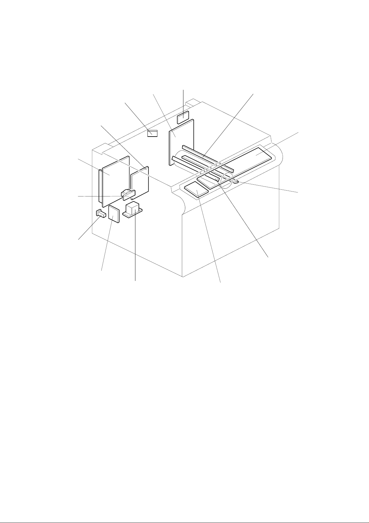
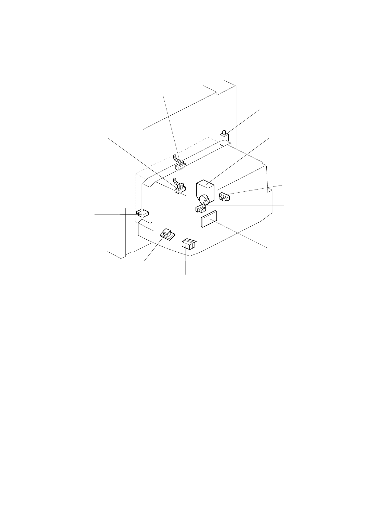
COPIER ELECTRICAL COMPONENT LAYOUT
5
11
10
14
13
12
9
11
2
3
4
8
7
6
Page 2
17
30
46
45
44
43
47
15
16
18
19
20
21
22
42
41
40
39
38
37
36
35
34
33
32
23
24
25
26
27
28
29
31
Page 3
53
48
49
70
69
68
67
66
50
65
64
63
62
61
60
59
58
57
51
52
54
55
56
Page 4
74
84
95
94
93
96
97
71
72
73
75
76
77
92
91
90
89
88
87 86
78
79
80
81
82
83
85
Page 5
107
98
105
106
99
100
101
102
104
103
Page 6

Description Index No. P to P Location
CB High Voltage Supply Board
(PCB5)
Erase Lamp (L6) 2 H2
Operation Panel Bo ard (P CB7 ) 3 F2
Pre-transfer Lamp (L4) 4 D13
Quenching Lamp (L5) 5 D14
Liquid Crystal Display Board
(A156 machines only) (PCB10)
Transformer
(220 ~ 240V machines only) (TR1)
Nose Filter Board
(220 ~ 240V machines only) (PCB8)
Circuit Breaker
(220 ~ 240V machines only) (CB1)
Choke Coil (CC1) 10 B9
DC Power Supply Board (PCB3) 11 C9
AC Drive Board (PCB2) 12 C6
Auto Image Density Sensor
(ADS Sensor) (S25)
Main Control Board (PCB1) 14 F13
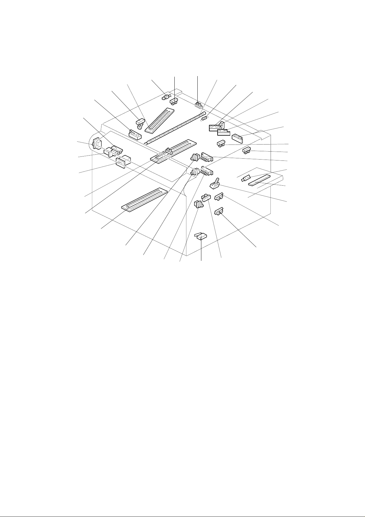
Scanner HP Sensor (S17) 15 G10
Platen Cover Sensor (S21) 16 D13
Exposure Lamp (L1) 17 A6
Exposure Lamp Thermofuse (TF3) 18 A6
Original Length Sensor-1 (S27) 19 D7
Lens Vertical HP Sensor (S16) 20 G10
Original Length Sensor-2 (S19) 21 D14
Original Length Sensor
(Option for N. American mo dels (S 33)
Transfer Belt Conta ct HP Sensor
(S24)
3rd Scanner HP Sensor (S 18 ) 24 F9
Upper Tray Paper Size Switch
(Non-duplex machines only) (SW5)
LCT Upper Limit Sensor
(LCT machines only) (S11)
By-pass Feed Paper Width Senso r
(S1)
Registration Sensor (S12) 28 H10
1A2
6E2
7C3
8A2
9A2
13 D8
22 D11
23 D12
25 G16
26 J13
27 J16
Page 7

Description Index No. P to P Location
Upper Tray Upper Limit Sensor
(A153/A155 machines only) (S5)
Lower Tray Upper Limit Sensor
(A153/A155/A 15 6 mach ines only)
(S8)
By-pass Feed Paper End Se nsor (S2) 31 H10
Vertical Guide Set Switch
(Non-LCT machines only) (SW7)
By-pass Feed Table Switch (SW1) 33 I10
Lower Tray Paper Size Switch (SW6) 34 H16
Lower Tray Switch (SW3) 35 G11
Upper Tray Switch
(Non-duplex machines only) (SW2)
Lower Tray Heater (option) (H3) 37 A5
Drum Heater (H1) 38 A4
Lens Horizontal HP Sensor (S15) 39 G10
Total Counter (CO1) 40 D11
Front Cover Safety Switch (SW11) 41 C10
Main Switch (SW10) 42 B8
Auto Response Senso r (S23 ) 43 F1
Original Width Sensor (S26) 44 D8
Fusing Exit Sensor (S20) 45 D14
Optics Anti-condensation Heater
(option) (H2)
Optics Thermistor (TH3) 47 D4
29 I16
30 J16
32 J16
36 G11
46 A5
Page 8

Description Index No. P to P Location
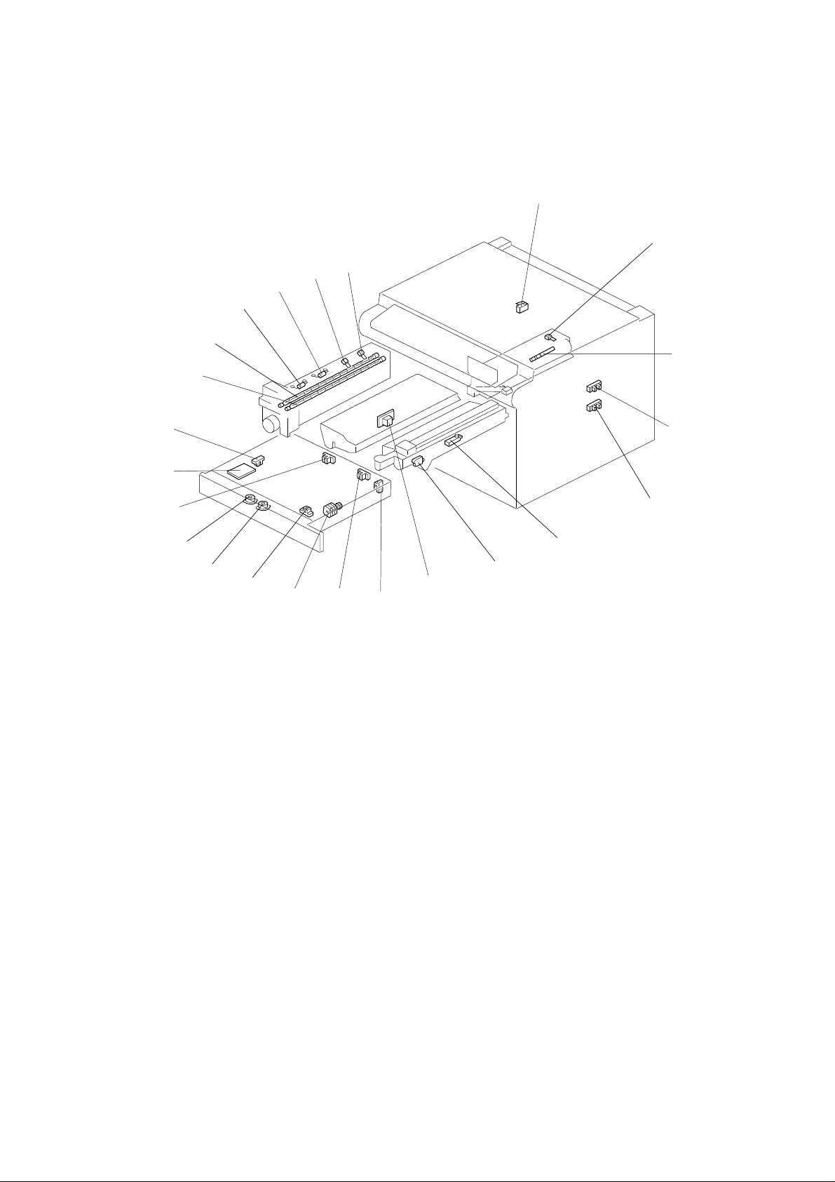
Exit Cover Safety Switch
(A157/A159/A160 machines only)
(SW12)
Drum Charge Thermistor (TH4) 49 I2
Image Density Sensor (ID) (S13) 50 I3
Upper Tray Paper End Sensor
(Non-duplex machines only) (S3)
Lower Tray Paper End Sensor (S6) 52 I16
Toner Density Sensor (TD) (S14) 53 I3
Toner End Sensor (S22) 54 D13
T High Voltage Supply Board (PCB6 ) 55 B12
Duplex Paper End Sensor
(Duplex machines only) (S28)
Duplex Turn Sensor
(Duplex machines only) (S29)
Duplex Feed Motor
(Duplex machines only) (M14)
Side Fence Jogger HP Sensor
(Duplex machines only) (S31)
Side Fence Jogger Motor
(Duplex machines only) (M16)
End Fence Jogger Motor
(Duplex machines only) (M15)
Duplex Entrance Sensor
(Duplex machines only) (S30)
Duplex Control Board
(Duplex machines only) (PCB9)
End Fence Jogger HP Sensor
(Duplex machines only) (S32)
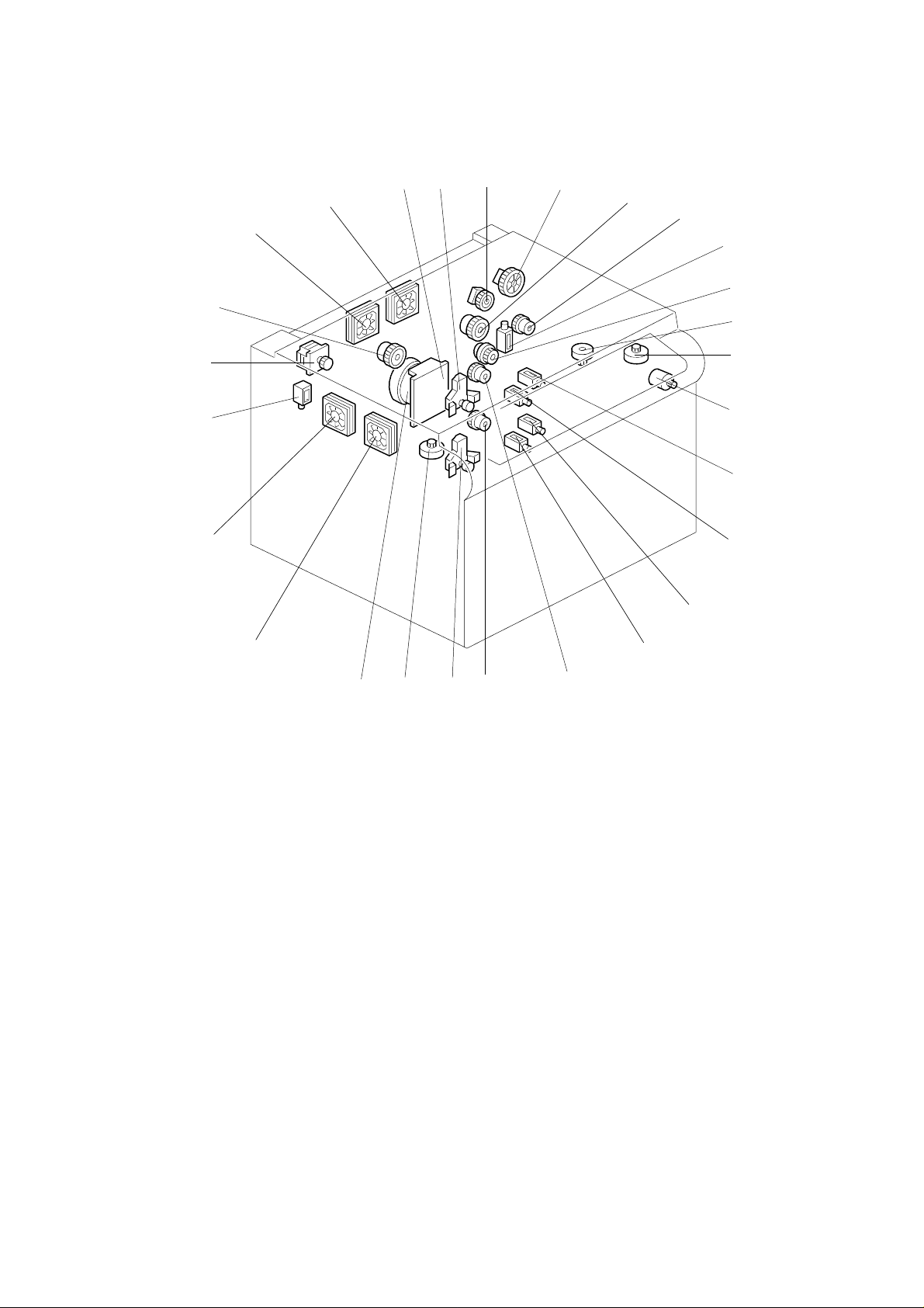
Main Fusing Lamp (L2) 65 A7
Secondary Fusing Lamp (L3) 66 A8
Secondary Fusing Thermofuse (TF2) 67 B7
Main Fusing Thermofuse (TF1) 68 A7
Main Fusing Thermistor (TH1) 69 D12
Secondary Fusing Thermistor (TH2) 70 C12
Development Clutch (CL2) 71 D6
Toner Supply Clutch (CL1) 72 D5
Registration Clutch (CL4) 73 I10
By-pass Feed Clutch (CL5) 74 I10
48 D10
51 H16
56 K5
57 K5
58 J8
59 K6
60 K5
61 K4
62 K6
63 J5
64 K6
Page 9

Description Index No. P to P Location
LCT machines:
LCT/By-Pass Pick up Solenoid
Non-LCT machines:
By-Pass Pick up Solenoid (SOL1)
Relay Clutch (CL6) 76 K16
Lens Horizontal Drive Motor (M13) 77 G9
3rd Scanner Drive Motor (M11) 78 G8
Toner Bottle Drive Motor (M2) 79 D6
Upper Tray Pick-up Solenoid
(A153/A155 machines only) (SOL4)
Upper Tray Separation Soleno id
(A153/A155 machines only) (SOL6)
Lower Tray Pick-up Solenoid
(A153/A155/A156 machines only)
(SOL5)
Lower Tray Separation Solenoid
(A153/A155/A156 machines only)
(SOL7)
Upper- Paper Feed Clutch
(Non-duplex machines only) (CL7)
Lower Paper Feed Clutch (CL8) 85 E16
Lower Tray Lift Motor
(A153/A155/A156 machines only)
(M4)
Lens Vertical Drive Motor (M12) 87 G8
Main Motor (M1) 88 D10
Exhaust Fan Motor 1 (M8) 89 D5
Exhaust Fan Motor 2
(A153/A155/A156 machines only)
(M9)
Junction Gate Solenoid
(Duplex machines only) (SOL2)
Scanner Drive Motor (M10) 92 F7
Transfer Belt Contact Clutch (CL3) 93 D11
Optics Cooling Fan Motor 1 (M6) 94 D4
Optics Cooling Fan Motor 2
(A153/A155/A156 machines only)
(M7)
Main Motor Control Board (PCB4) 96 D9
Upper Tray Lift Motor
(A153/A155 machines only) (M3)
75 I10
80 E16
81 F16
82 F16
83 F16
84 E16
86 G16
90 D5
91 G7
95 D5
97 F16
Page 10

Description Index No. P to P Location
LCT Pick-up Solenoid
(LCT machines only) (SOL3)
LCT Lift Motor (LCT machines only)
(M5)
LCT Lower Limit Sensor
(LCT machines only) (S9)
LCT Paper End Sensor
(LCT machines only) (S10)
LCT Interface Board
(LCT machines only) (PCB11)
LCT Cover Switch-2
(LCT machines only) (SW9)
Tray Down Switch
(LCT machines only) (SW4)
LCT Cover Switch-1
(LCT machines only) (SW8)
Lower Relay Sensor (S7) 106 I16
Upper Relay Sensor (S4) 107 H16
98 J14
99 L11
100 J12
101 J13
102 K12
103 K12
104 J13
105 J12
Page 11

2
20 BIN SORTER (A556) ELECTRICAL CO MPO NENT LAY OUT
1
7
6
5
4
3
Description Index No. P to P Location
Paper Sensor (S1) 1 G15
Wheel Drive Motor (M1) 2 C15
Roller Drive Motor (M2) 3 E15
Bin Home Position Sensor (S2) 4 I15
Wheel Sensor (S3) 5 H15
Sorter Control Board (PCB1) 6 F8
Cover Safety Switch (SW1) 7 J15
Page 12

1
10 BIN SORTER (A557) ELECTRICAL CO MPO NENT LAY OUT
7
6
5
4
3
Description Index No. P to P Location
Sorter Main Board (P CB1 ) 1 F8
Wheel Switch (SW1) 2 H14
Roller Drive Motor (M1) 3 E14
Paper Sensor (S1) 4 J14
Bin Drive Motor (M2) 5 C14
Sorter Switch (SW2) 6 I14
Home Position Switch (SW3) 7 G14
2
Page 13

5
ARDF (A548) ELECTRICAL COMPONENT LAYOUT
2
3
1
4
18
17
16
15
Description Index No. P to P Location
Original Set Sensor (S1) 1 B3
Feed-in Cover Open Sensor (S2) 2 E3
Stopper Solenoid (SOL1) 3 I16
Ready Lamp (L1) 4 D3
Auto Lamp (L2) 5 C3
Feed-in Motor (M1) 6 C16
Belt Drive Motor (M2) 7 E16
DF Main Board (PCB1) 8 F11
Inverter Solenoid (SOL 2) 9 J16
Feed-out Cover Open Sensor (S3) 10 J3
Feed-out Motor (M3) 11 F16
Feed-out Sensor (S4) 12 I3
APS Start Sensor (S5) 13 L3
DF Position Sensor (S6) 14 K3
Original Width Sensor-1 (S7) 15 H3
Original Width Sensor-2 (S8) 16 G3
Original Width Sensor-3 (S9) 17 F3
Registration Sensor (S10) 18 A3
6
7
8
9
12
13
14
10
11
Page 14

4
PAPER TRAY UNIT (A553) ELECTRICAL COMPONENT LAYOUT
1
2
3
5
6
7
8
14
13
9
10
1112
Page 15

Description Index No. P to P Location
Interface Board (PCB1) 1 F8
Tray Set Switch 1 (SW2) 2 H2
Tray Set Switch 2 (SW3) 3 I2
Main Motor (M1) 4 G2
Paper End Sensor 1 (S3) 5 G16
Paper End Sensor 2 (S4) 6 G16
Paper Feed Clutch 1 (CL1) 7 I16
Paper Feed Clutch 2 (CL2) 8 I16
Relay Clutch (CL3) 9 H16
Relay Sensor 1 (S1) 10 B16
Relay Sensor 2 (S2) 11 C16
Tray Cover Switch (SW1) 12 B16
Tray Heater (Option) (H1) 13 C6
Tray Heater (Option) (H2) 14 D6
Page 16

4
5
17
18
PAPER TRAY UNIT (A549/A550) ELECTRI CAL CO MPO NENT LAYOUT
29
28
27
30
26
12
3
6
7
8
9
10
11
12
13
14
15
16
25
24
23
202122
19
Page 17

Description Index No. P to P Location
Interface Board (PCB1) 1 F8
Tray Lift Motor 1 (M2) 2 E2
Tray Set Switch 1 (SW2) 3 H2
Tray Set Switch 2 (SW3) 4 H2
Main Motor (M1) 5 F2
Tray Set Switch 3 (A549 only) (SW4) 6 I2
Tray Upper Limit Sensor 1 (S1) 7 E16
Paper Pick-up Solenoid 1 (SOL1) 8 D16
Paper Feed Clutch 1 (CL1) 9 K16
Separation Solenoid 1 (S O L4) 10 E16
Relay Clutch (CL4) 11 J16
Paper Feed Clutch 2 (CL2) 12 K16
Paper Pick-up Solenoid 2 (SOL2) 13 F16
Separation Solenoid 2 (SOL5) 14 G16
Paper Feed Clutch 3 (A549 only)
(CL3)
Paper Pick-up Solenoid 3
(A549 only) (SOL3)
Separation Solenoid 3 (A549 only)
(SOL6)
Tray upper Limit Sensor 2 (S2) 18 G1 6
Tray upper Limit Sensor 3
(A549 only) (S3)
Relay Sensor 3 (A549 only) (S6) 20 C16
Paper End Sensor 3 (A549 only) (S9) 21 H16
Tray Cover Switch (SW1) 22 A16
Relay Sensor 2 (S5) 23 B16
Paper End Sensor 2 (S8) 24 F16
Relay Sensor 1 (S4) 25 B16
Tray Heater (Option) (H1) 26 B6
Tray Heater (Option) (H2) 27 C6
Paper End Sensor 1 (S7) 28 C16
Tray Lift Motor 3 (A549 only) (M4) 29 F2
Tray Lift Motor 2 (M3) 30 E2
15 L16
16 I16
17 J16
19 I16
Page 18

10 BIN SORTER STAPLER (A5 55 ) E LECTRI CAL CO MPNENT
3
LAYOUT
16
15
17
14
13
1
2
4
5
6
7
12
11
19
10
8
9
18
Page 19

Description Index No. P to P Location
Bin Sensor (Photo tr.) (S1) 1 I15
Sorter Entrance Sensor (S2) 2 F15
Grip Motor (M5) 3 I2
Stapler Paper Sensor (S5) 4 A15
Grip H.P. Sensor (S6) 5 B15
Stapler Motor (M4) 6 E1
Stapler Switch (SW2) 7 F5
Door Safety Switch (SW1) 8 C5
Jogger Motor (M2) 9 H2
Wheel Sensor (S8) 10 C15
Bin Sensor (LED) (S7) 11 K15
Bin H.P. Sensor (S9) 1 2 H15
Timing Sensor (S4) 13 G15
Transport Motor (M1) 14 E16
Jogger H.P. Sensor (S3) 15 J15
Bin Drive Motor (M3) 16 K2
Main Board (PCB1) 17 F8
Staple H.P. Sensor (S10) 18 E1
Staple End Sensor (S11) 19 E1
Page 20

20 BIN SORTER STAPLER (A55 4) ELECTRICAL COMPONENT LAYOUT
21
25
24
23
22
21
20
19
18
17
3
4
5
6
7
8
13
14
15
16
9
10
11
12
Page 21

Description Index No. P to P Location
Roller Drive Motor (M5) 1 B2
Roller Drive Timing Sensor (S11) 2 C3
Bin Sensor (LED) (S5) 3 J16
Proof Tray Exit Sensor (S10) 4 D3
Bin Exit Sensor (S9) 5 D3
Turn Gate Solenoid (SOL1) 6 E3
Sorter St apler Set Swi tch (SW4) 7 L4
Paper Sensor (S4) 8 I16
Staple Guide Switch (SW6) 9 G2
Staple End Switch (SW5) 10 G2
Staple H.P. Switch (SW7) 11 G2
Stapler Motor (M4) 12 F3
Grip Motor (M3) 13 I2
Front Door Switch (SW3) 14 L5
Bin H.P. Sensor (S8) 1 5 H3
Grip H.P. Sensor (S7) 16 J3
Bin Sensor (Photo tr.) (S6) 17 K16
Main Control Board (PCB1) 18 F 9
Jogger H.P. Sensor (S3) 19 E16
Jogger Motor (M2) 20 G16
Wire Tension Switch (SW2) 21 B16
Upper Lift Limit Switch (SW1) 22 B16
Bin Lift Motor (M1) 23 A16
Bin Lift Timing -1 Sensor (S1) 24 C16
Bin Lift Timing -2 Sensor (S2) 25 D16
 Loading...