

Page 1

10-BIN
SORTER STAPLER
(Machine Code: A555)
Page 2
13th January 1995 SPECIFICATIONS
1. SPECIFICATIONS
Paper Size for Bins: Sort/Stack Modes:
Maximum: A3, 11 x 17"
Minimum: B5, 81/2 x 11"
Paper Weight for Bins: Sorting:
52 ~ 157 g/m2 (14 ~ 42 lb)
Stacking:
52 ~ 157 g/m2 (14 ~ 42 lb)
Stapling:
52 ~ 80 g/m2 (14 ~ 21 lb)
Bin Capacity: Sorting:
A4, 81/2 x 11" or smaller: 30 copies
B4, 81/2 x 14" or larger: 25 copies
Stacking:
A4, 81/2 x 11" or smaller: 25 copies
B4, 81/2 x 14" or larger: 20 copies
Stapler Capacity: 2 ~ 20 copies
Proof Tray Capacity: 100 copies (52 ~ 80 g/m2 / 14 ~ 21 lb)
50 copies (81 ~ 128 g/m2 / 22 ~ 34 lb)
30 copies (129 ~ 157 g/m2 / 35 ~ 42 lb)
Number of Bins: 10 bins + proof tray
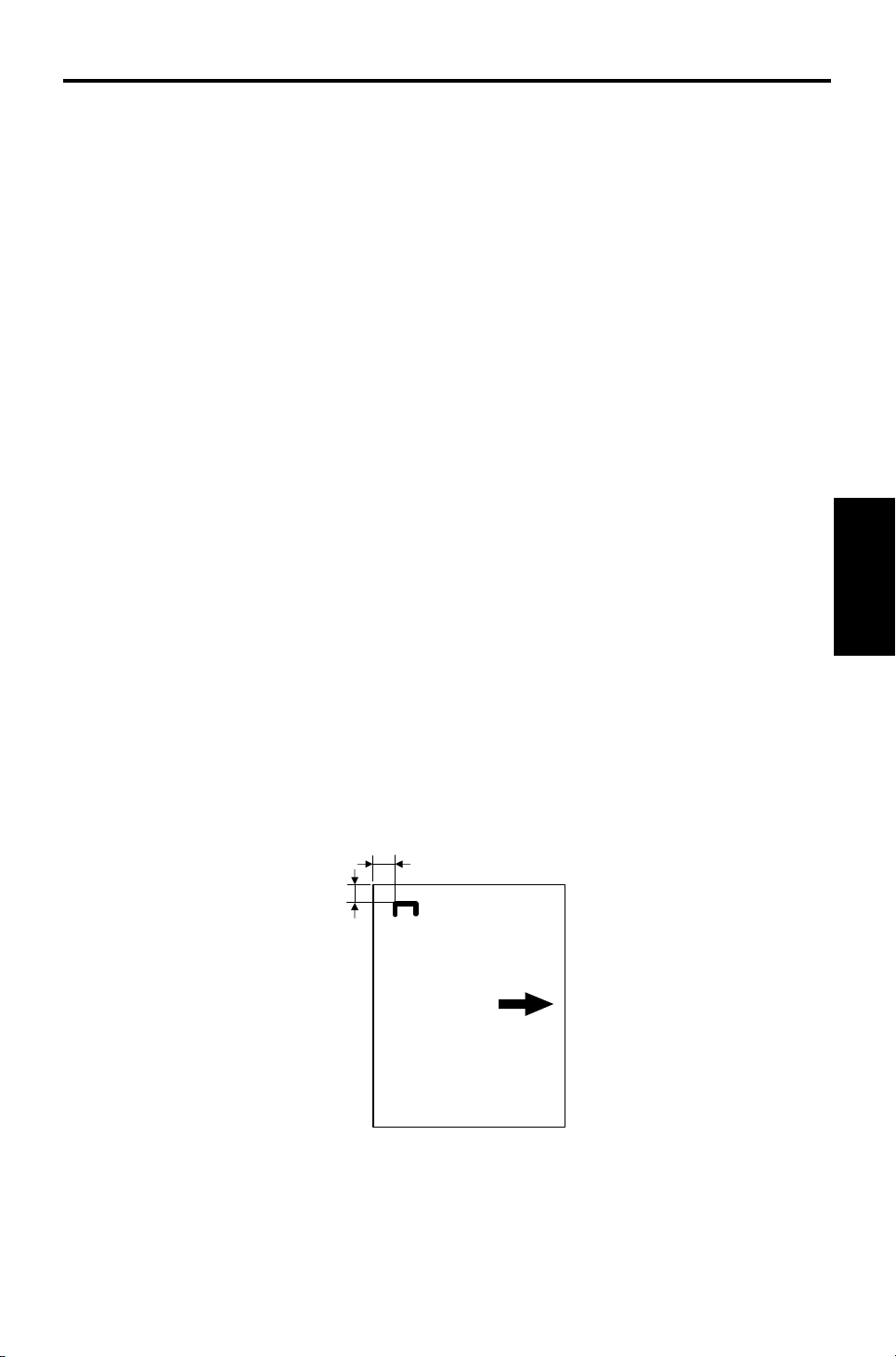
Stapling Position:
a = 6 ± 3 mm
b = 6 ± 3 mm
a
b
Stapler
10-bin Sorter
1
Page 3

SPECIFICATIONS 13th January 1995
Staple Replenishmen t: Cartridge exchange (2,00 0 sta ple s/cartridge)
Power Source: DC 24V, 5V (from the copier)
Power Consumption: Average: less than 33 W
Average for Sorting: less tha n 25 W
Average for Stapling : less th an 33 W
Weight: 12.4 kg (27.4 lb)
Dimensions (W x D x H): 381 x 548 x 443 mm (15.0" x 21.6" x 17.5")
2
Page 4
13th January 1995 COMPONENT LAYOUT
2. COMPONENT LAYOUT
2.1 MECHANICAL COMPONENT LAYOUT
1
2
7
3
6
5
1. Helical Wheels
2. Jogger Plate
3. Grip Assembly
4. Transport Rollers
5. Staple U nit
6. Bins
7. Proof Tray
4
Stapler
10-bin Sorter
3
Page 5
COMPONENT LAYOUT 13th January 1995
2.2 DRIVE LAYOUT
1
8
2
3
4
7
1. Jogger Drive Belt
2. Transport Roller
3. Helical Wheels
4. Transport Motor
6
3
1
5
5. Jogger Motor
6. Wheel Drive Belts
7. Bin Drive Motor
8. Jogger Plate
4
Page 6

13th January 1995 COMPONENT LAYOUT
2.3 ELECTRICAL COMPONENT DESCRI P TI ON
Refer to the electrical compone nt layou t on the reverse side of the Poin t to
Point Diagram (on waterproof paper).
Symbol Index No. Description Note
Motors
M1 14 Transport Drives the transport roller
M2 9
M3 16 Bin Drive Drives the bins
M4 6 Stapler Drives the stapler hammer
M5 3
Sensors
S1 1
S2 2 Sorter Entrance Detects paper jams
S3 15
S4 13
S5 4
S6 5
S7 11
S8 10 Wheel Detects the bin position.
S9 12
S10 18
S11 19 Staple End Detects when the staples run out
Switches
SW1 8
SW2 7 Stapler Cuts the signals to the stapler.
Circuit Board
PCB1 17 Main Controls all sorter/stapler functions
Jogger Drives the jogger plate to square the
copies
Grip Drives the grippers forwards and back
into the bin to grip the copies and
bring them to the stapling position
Bin
(Phototransistor)
Jogger H.P. Detects whether the jogger plate is in
Timing Provides pulses to the sorter stapler
Stapler Paper Detects whether any copies are under
Grip H.P. Detects when the grip assembly cam
Bin
(LED)
Bin H.P. Detects whether the bins are at home
Staple H.P. Detects whether the stapler hammer
Door Safety Cuts the dc +24V supply when either
Detects whether there is any paper in
the bins (light receiving element)
its home position
main board.
the hammer.
gear has rotated once
Detects whether there is paper in the
bins (light emitting element)
position
is at home position
the unit or the stapler cover is opened.
Stapler
10-bin Sorter
5
Page 7
BASIC OPERATION 13th January 1995
3. BASIC OPERATION
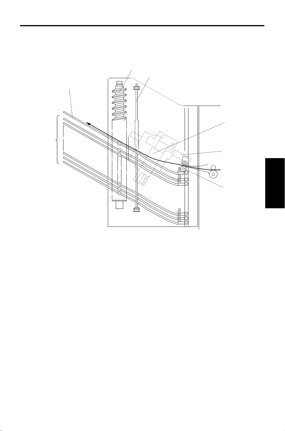
3.1 NORMAL MODE AND SORT/STACK MODE
[E]
[A]
[B]
[D]
Copies exiting the copier pass thro ug h the entrance guide plate [A]. The
transport roller will send copies eit he r to th e pro of tray or to each bin,
depending on the select ed mode .
During copying, all rollers in the sorter stapler transport the paper at a speed
which depends on the copier. When the trailing edge of th e copy passes the
fusing exit sensor, the speed of the rollers changes to 600 mm/s. This ma kes
enough time for the jogger plate to squa re the sta ck of pa per a nd to sta ck the
paper smoothly into the bins.
- Normal (proof) mode -
When the Start key is pressed, the tran sport motor [B] energizes to rota te the
transport roller. The transport roller sends copies to the proof tray directly.
- Sort mode -
When sort mode is selected, the bin drive motor [C] energize s to rotat e the
helical wheels. The helical wheels [D] rotate twice to move the top bin to the
transport roller position , then the first cop y is delivered to the top bin.
[C]
After the first copy of the first origina l h as been fed to th e top bin , th e bin
drive motor moves the bins up one step (the helical wheels rotate once) so
that the second copy of the first orig inal will be delivered to the next bin .
The jogger plate [E] squares the copies after each copy has been fed to a
bin. After the copies of the first orig ina l h ave been delivered to each bin, the
sorter stapler maintains its status (t he bin drive moto r does not rota te ).
6
Page 8
13th January 1995 BASIC OPERATION
The first copy of the second origina l is delivere d to the fina l bin th at was used
for the first original, the n th e fin al bin descends one step. The bins de scend
each time a copy of the seco nd original is delivered.
The direction of motion of the bins alt ern at es fo r each page of the original
until the copy run is finished.
- Stack mode -
[A]
When stack mode is selected, the top bin advances to the transport roller
position in the same way as in sort mode.
After the first copy is delive red to the top bin, the jogger plate [A] moves
across to square the copy. The jogger plate squares th e copies after each
copy has been fed to a bin.
After one set of copies for the first orig ina l h as been delive red to the to p bin ,
the bin drive motor moves th e bin s up on e ste p. Then, one set of copies of
the second original will be delivered to the next bin.
Stapler
10-bin Sorter
7
Page 9
BASIC OPERATION 13th January 1995
3.2 STAPLE MODE
[B]
[A]
[C]
[D]
The stapler is only available in sort mode.
When the jogger plate has square d th e fin al set of cop ies, the grip arms [A ]
move inside the front side frame and catch the pape r. The grip asse mbly
brings the copies into the stapler [B], and the stapler staples the copies.
After stapling, the grip asse mbly [C] brings the stapled copies back to the bin
and releases the copies. Then the grip asse mbly goes ba ck to th e no rmal
position. The bin eithe r a dva nces or descends one step depen ding on
whether the number of originals is odd or even [D].
When the final set of copies has been stapled, the bins go back to the
standby position.
8
Page 10

13th January 1995 BASIC OPERATION
There are two staple modes.
Automatic Stapling
In ADF mode, when staple mod e is selected before pressing th e St art key,
copies will be delivered to each bin and stap led aut oma tica lly.
Manual Stapling
In platen cover mode, after the copies have been sorted into the bins, the
staple mode LED starts to blink. If the sort key is presse d while this LED is
blinking, the copies will be stapled.
Stapler
10-bin Sorter
9
Page 11

BASIC OPERATION 13th January 1995
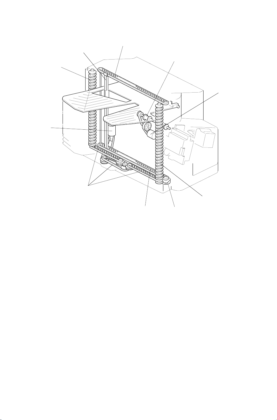
3.3 BIN DRIVE MECHANISM
[A]
[A]
[B]
[C]
[D]
The bin drive mechanism moves th e bin s up an d do wn to receive copies.
There are four pins on each bin . Two pins fit into the slots [A] in bot h th e front
and rear side frames; the pin s slide up and down in these slots. The other
two pins fit into the slot in the helical wh eels; as th e helical wheels turn, these
pins move up and down, and the oth er pins move up and down in the slots at
the other end of the bin.
The bin drive motor [B] drives the helical wheels thro ug h four timin g belts [C] .
When the motor rotates clockwise, the bins lift; whe n it rot ates
counterclockwise, the bins lower. There is a wheel sensor actuator [D] on the
front helical wheel; the actu at or has a slo t which det ect s when the helica l
wheel has rotated once.
When the bins are advanced, the helical wheels rotate once for each step. As
the pitch of the spiral on the helical wheel is greater when the bins are at the
staple and paper exit area th an wh en the bins are elsewhere, the amoun t of
bin shift is greater when the bins are at the sta ple and pap er exit area . This
leaves enough space to stap le an d stack the copies. Also, this re du ces th e
total machine height.
10
Page 12

13th January 1995 BASIC OPERATION
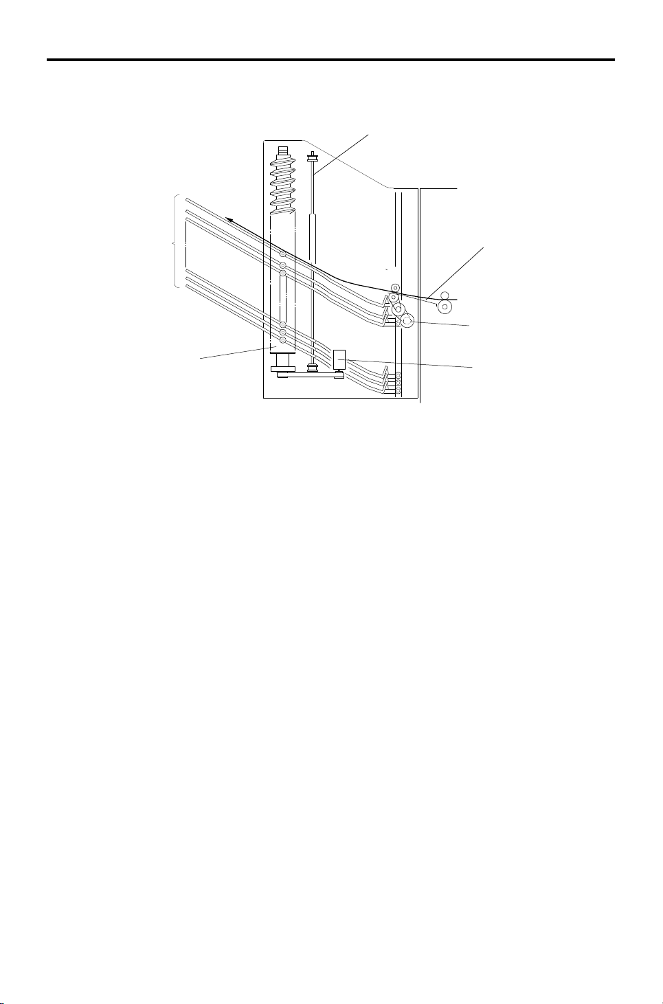
3.4 BIN HOME POSITION
[A]
The bin home position senso r [ A] ensu res that the proof tray is lower t ha n th e
transport roller when the bins are in the home position.
When the main switch is turned on, the sorter staple r initia lizes itself to check
whether the component parts work or not. At this time , th e bin drive mot or
raises the bins for a few moments, then it lowers the bins until th e bott om bin
actuates the bin home posit ion sensor.
Stapler
10-bin Sorter
11
Page 13

BASIC OPERATION 13th January 1995
3.5 JOGGER MECHANIS M
[B]
[E]
[D]
[C]
[A]
The jogger motor [A] drives the jogge r plate [B] through the timing belt s [C].
The jogger is at home position when the actuator on the jo gger plate goes
into the jogger home position sen sor [D] .
At standby, the jogger plate is at the home position. When the Start ke y is
pressed, the copier sends the paper size informa tio n to the sorte r stap ler.
In sort, staple, and sta ck mo de s, th e jogger moves three times to squa re the
stack of paper. First, whe n th e pa pe r has be en fed comple tely into the bin (at
the proper time after th e copy has passed through th e en tra nce sensor [E],
depending on the paper length), the jogger mot or moves the jogger plate out
of the jogger home posit ion. Then, the jogger mot or drives the jogger plate to
the width of the copy. Finally, the jogger plate moves inward to push all the
copies against the fron t side frame, which squares the sheets of paper. Then
the jogger plate returns to the home position.
12
Page 14

13th January 1995 BASIC OPERATION
3.6 GRIP ASSEMBLY
[G]
[H]
[I]
[J]
[D]
[B]
[E]
[C]
[F]
[A]
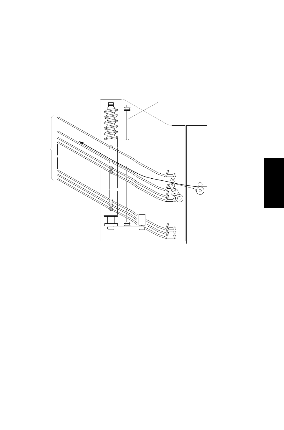
The grip assembly consists of the grip motor [A], the timin g belt [B ], the drive
gear [C], the grip home position sen sor [D] , an d the cam gear [E].
The grip motor drives the cam gear through the timing belt and drive gear.
Cam gear rotation drives the mechanism that ca tch es the copies and moves
the grip arm unit [F]. When the cam gear rotates clockwise one full turn, the
grip arm moves to catch the copies an d returns to the home positio n to
prepare for stapling. After stapling, the cam gear rotate s counte rclockwise
once so that the staple d copies go back to the bin, and the cam gea r re tu rns
to its home position.
Stapler
10-bin Sorter
When the cam pushes the roller [G] on the lever [H] and the lever pushes the
grip arm, the grip arm can catch the copies.
A pin [I] on the cam gear fits into the slot in the grip arm un it. So, when the
cam gear rotates, the slot moves the grip arm unit inward and outward.
The actuator [J] on the cam gear activates the grip home positio n sen sor
once every rotation of the cam gear. This allows th e sort er sta pler to
determine that the cam gear has rotated once.
13
Page 15

BASIC OPERATION 13th January 1995
3.7 STAPLER UNIT
[C]
[D]
[A]
[F]
[G]
[H]
[E]
[B]
The stapler motor [A] drives the staple hammer [B] using the gears [C] and
the eccentric cam [D].
The roller [E] feeds the staple sheets un de r the hamme r.
When the aligned copies are brought to the staple position by the grip unit,
the stapler motor starts rotat ing and the copies are stapled. Wh en the cam
completes one rotation, the staple ho me po sitio n sen sor [F] is deact ua te d
and the stapler motor stops.
When the stapler paper sensor [G] in the grip asse mbly does no t de te ct an y
copies under the hammer, the stap ler mot or do es not rotate.
When the trailing edge of th e last staple sheet pass throu gh the stap le en d
sensor [H], the sorter stap ler en ters t he st aple ne ar end con dition. After the
current job is completed, th e Ad d St ap les ind icator lights on the operation
panel. Then the copie r cann ot be use d whenever the staple mode is
selected.
14
Page 16

13th January 1995 BASIC OPERATION
3.8 STAPLER SWITCH
[A]
[B]
The stapler switch [A] be low th e grip assembly cuts the signal to the stap ler.
In proof mode, all bins lower and pu sh th e leve r [ B] . This open s the st apler
switch so that the signal to the staple r is cut. In sort an d sta ple mode s, all
bins are advanced and the switch is closed so that the signal ca n be supplied
to the stapler.
- Staple Disabling Conditions -
1. Under the following conditions, staple mode is disabled.
If there is paper in a bin before the main switch is turned on.
If the selected paper size does not match the stapling specification s.
If the paper is fed from the by-pass feed table.
If the stack or interrupt modes are selected.
2. Under the following conditions, staple mode is canceled if it had been
selected.
Stapler
10-bin Sorter
If paper is inserted into a bin by hand while the stap le mod e is select ed .
If only one sheet is delivered to th e bin.
If the number of sheets to be stapled exceeds th e sta pler capacity.
15
Page 17

BASIC OPERATION 13th January 1995
3.9 PAPER FEED AND MISFE ED DE TECTION TIMING
– Proof Mode –
A4 sideways, 5 copies, 150 mm/s
*1: The value of the low sp ee d depe nd s on th e copier.
– Sorter Mode –
A4 sideways, two copies a of two-page original, 150 mm/s
*1: The start timing of the bin drive and the jogger motors depend on the
paper size as shown in the following table.
*2: Bin No.
Paper Size
A3/11"x17" 138 ms 292 ms
B4 218 ms 212 ms B5 sideways 218 ms 212 ms
A4 sideways/
11"x8
1/2"
Bin drive
motor timing
138 ms 292 ms B5 lengthwise 368 ms 62 ms
Jogger motor
timing
Paper Size
lengthwise/
1/2"x11"
8
16
A4
Bin drive
motor timing
312 ms 118 ms
Jogger motor
timing
Page 18

13th January 1995 BASIC OPERATION
– Staple Mode –
A4 sideways, two copies of a two-page origin al, aft er sorting, 150 mm/s
Stapler
10-bin Sorter
17
Page 19

BASIC OPERATION 13th January 1995
3.10 JAM DETECTION
– Paper Jam –
J1: The sorter entran ce sensor does not turn on within 2 s afte r t he fusing
exit sensor has turned on.
J2: The fusing exit senso r doe s not turn off within 11.4 s aft er the sorter
entrance sensor has turned on.
J3: The sorter entran ce sensor does not turn off with in 1 s aft er the fusing
exit sensor has turned off.
– Staple Jam –
In the following condit ion s, a staple jam will occur and the sorter jam indicator
on the operation panel will light.
1. If the stapler paper sensor is on when the main swit ch tu rns on or ju st as
the stapler cover is closed.
2. If the stapler paper sen sor sta ys o n af te r t he stap ling job ha s bee n
finished.
18
Page 20

13th January 1995 INSTALLATION
4. INSTALLATION
4.1 ACCESSORY CHECK
Check the quantity and cond itio n of the accessories in the box against the
following list:
1. Misfeed Removal Decal............. .. .. .... .. .. .. .. .. .. .... .. .. ..1
2. Staple Position Decal.............. .............. .. .. ..............1
3. Chain .......................................................................1
4. Cap Remover ...................... .. .. .. .. .............. .. .. ..........1
5. Philips Pan Head Screw 4 x 8......... .. .......... .. ..........1
6. Philips Pan Head Screw 4 x 14..................... .. .. .. .. ..4
7. New Equipment Condition Report............. .. .. .. .. .. ....1
8. Installation Procedure.................. .......... .......... ........1
Stapler
10-bin Sorter
19
Page 21

INSTALLATION 13th January 1995
4.2 INSTALLATION PROCEDURE
– Incorrect Lifting Method –
[A]
[B]
[B]
[C]
[B]
[C]
NOTE: When this unit is installed in the A157, A159, A160, A1 61 , an d A1 62
copiers, the sorter adapter (A5 68 ) shou ld be installed before the
sorter stapler.
CAUTION
!
Unplug the copier power cord before starting the fol low ing proc edur e.
Do not lift the sorter stapler by holding the entrance
guide [A]. Otherwise, the resul ting damage may cause paper jams to
occur at the entrance.
1. Remove the strips of tape.
[C]
2. Remove the cardboard pieces [B] and the foam blocks [ C].
20
Page 22

[D]
13th January 1995 INSTALLATION
– A153/A155/A156 copiers –
[A]
[D]
[B]
[D]
[B]
[C]
– A157/A159/A160/A161/A16 2 copiers –
[D]
[E]
[B]
[C]
3. Remove the caps [A] with nipp ers.
4. For A153, A155, and A156 copiers:
Fit the hooks [B] on the sorter stapler mounting frame [C] into the
openings [D]. Then tig ht en four M4 x 14 screws.
For A157, A159, A160, A161, and A162 copiers:
First, remove the screw [E], and fit th e ho oks [B ] on the sorte r stap ler
mounting frame [C] into the openings [D]. Then tighten four M4 x 14
screws.
Stapler
10-bin Sorter
21
Page 23

[F]
INSTALLATION 13th January 1995
– Incorrect Lifting Method –
[B]
[C]
[H]
[G]
[A]
[E]
[D]
5. Install the sorter stapler [A] on the frame [1 M4 x 8 screw].
NOTE: Do not lift the sorter stapler by holdin g the entrance guide [B]
when installing it.
6. Tighten 1 M4 x 8 screw [C].
NOTE: This screw prevents the sorter stapler from fa lling down .
7. Connect the cable [D] and th e op tic cable [E].
8. Install the chain [F] as shown .
9. Attach the misfeed removal decal [G] and th e sta ple posit ion deca l [ H] as
shown above.
22
Page 24

13th January 1995 INSTALLATION
[B]
[A]
[C]
[E]
[D]
10. Open the front door [A] of the sort er sta pler and swing the staple unit [B]
up.
11. Remove the green plastic clip [C] from th e staple cartridge and correct
the position of the sta ple sheet [D] to make it flush with the other sheets
in the cartridge.
12. Install the cartridge [E] in the staple r while ho ldin g the staple unit.
13. Put the staple unit back to the orig ina l position, close the sorter stap ler
front door, and plug in the copier.
14. Turn on the main switch, and test the operation of the sorte r stapler.
NOTE: The stapler will not be stapling for the first 5 or so copies after
installation until the first stap le come s to th e proper position from
the cartridge.
Stapler
10-bin Sorter
23
Page 25

SERVICE TABLES 13th January 1995
5. SERVICE TABLES
5.1 DIP SWITCHES
DIP SW100
Switch No.
1 2345
Off Off Off Off Off Normal Setting
On On Off Off Off Sorter Free Run
On Off On Off Off Staple Free Run
On On On Off Off System Free Run
Off Off Off Off On
Bin Jam Sensor Adjustment (see
section 6.6)
Using a Free Run Mode
1. Select the type of f ree ru n th at you need using switche s 2 and 3.
2. Set switch 1 to 1. The free run starts.
Function
3. To stop the free run, set switch 1 to 0.
4. Return switches 2 and 3 to their factory settin gs.
Free Run Mode Types
- Sorter Free Run Mode -
This mode advances and lowers the bins, moves the jogger plate, and
changes the roller rotation speed fro m lo w to hig h for e ach bin.
- Staple Free Run Mode -
This mode performs the jogger plate, grip assembly, and staple move men ts
for each bin.
- System Free Run Mode -
This mode performs both sorter free run and staple free run modes.
24
Page 26

13th January 1995 SERVICE TABLES
5.2 TEST POINTS
Number Function
TP100 +24 V
TP101 +5 V
TP102 GND
5.3 LED
Number Function
LED100 Bin jam sensor status
5.4 VARIABLE RESIS TOR
Number Function
VR100
Bin jam sensor (LED) adjustment
(see Bin Jam Sensor Adjustment)
Stapler
10-bin Sorter
25
Page 27

REPLACEMENT AND ADJUSTMENT 13th January 1995
6. REPLACEMENT AND ADJUSTMENT
6.1 EXTERIOR COVE R REMO VAL
[D]
[A]
[C]
[B]
1. Rear Cover [A] (2 screws)
2. Front Cover [B] (3 screws)
3. Lower Cover [C] (1 screw)
4. Top Cover [D] (2 screws)
6.2 STAPLE UNIT REMOVAL
[A]
1. Remove the front cover (see Exterio r Co ver Remo val).
2. Swing up the staple unit [A].
3. Remove the staple unit (1 connector, 1 ground wire, 1 clip).
26
Page 28

13th January 1995 REPLACEMENT AND ADJUSTMENT
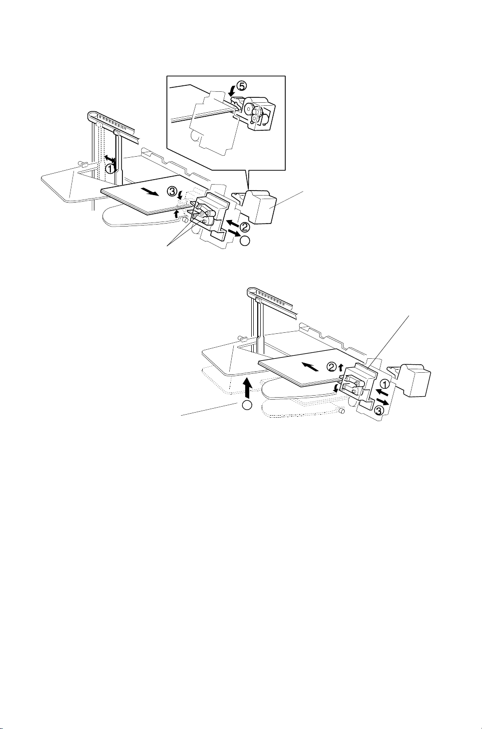
6.3 GRIP ARM REPLACEMENT
[A]
[D]
[C]
[E]
[B]
[G]
[F]
1. Remove the front cover (see Exterio r Co ver Remo val).
2. Remove the grip assembly [A] (4 screws, 2 connect ors, 1 grou nd ing wire).
3. Remove the holder bracket [B] (1 screw).
4. Remove the spring [C] and remove the slider [D].
5. Remove the grip arm unit [E] (1 screw, 1 clip).
Stapler
10-bin Sorter
6. Remove the grip arm plate [F] (2 screws).
7. Replace the grip arms [G].
27
Page 29

[F]
[J]
REPLACEMENT AND ADJUSTMENT 13th January 1995
6.4 BIN REPLACEMENT
[D]
[E]
[C]
[B]
[A]
[K]
[L]
[I]
[H]
[G]
[K]
[J]
[I]
[H]
1. Remove the front, rear, and top covers (see Exterior Cover Removal).
2. Remove the spring [A] and the grip cover [B] (2 screws).
3. Remove the upper stay bracket [C] (6 scre ws, 1 gro un din g wire, 1
connector).
4. Remove the timing belt [D].
5. Remove the jogger guide plate [E ] (4 screws).
6. Remove the wheel sensor bracket [F] (1 screw).
7. Remove the bushings [G] (1 clip each).
8. Remove the actuators [H], belts [I ], and the gears [J] (1 clip on each side).
9. Remove the helical wheels [K].
10. Remove the bins [L].
NOTE: When putting back the he lical wheels at both the front and re ar of the
machine, the parts labeled A should be pointing direct ly away from
the machine.
28
Page 30

[B]
[G]
13th January 1995 REPLACEMENT AND ADJUSTMENT
6.5 TRANSPORT MOTOR REPLACEMENT
[A]
[C]
[E]
[F]
[D]
[H]
1. Remove the sorter stapler [A] (1 screw, 1 chain ).
2. Remove the lower plate [B] (3 screws).
3. Remove the entrance guide [C] (4 screws).
4. Remove the transport motor unit [D].
5. Remove the collar [E].
6. Remove the transport roller [F] (2 bushings, 1 gear).
Stapler
10-bin Sorter
7. Remove the transport motor cover [G].
8. Remove the transport motor [H] (3 screws).
29
Page 31

REPLACEMENT AND ADJUSTMENT 13th January 1995
6.6 BIN JAM SENSOR ADJUS TMENT
After replacing the sorter main board, perform the bin jam sensor adju stme nt
as follows.
1. Turn on the main switch.
2. Remove any copies from the bins.
3. Set switch 5 of DIP SW 100 on the sorter main board to the ON position.
4. Turn VR 100 until LED 100 goes off.
30
Page 32

Page 33

10 BIN SORTER STAPLER (A5 55 ) E LECTRI CAL CO MPNENT
3
LAYOUT
16
15
17
14
13
1
2
4
5
6
7
12
11
19
10
8
9
18
Page 34

Description Index No. P to P Location
Bin Sensor (Photo tr.) (S1) 1 I15
Sorter Entrance Sensor (S2) 2 F15
Grip Motor (M5) 3 I2
Stapler Paper Sensor (S5) 4 A15
Grip H.P. Sensor (S6) 5 B15
Stapler Motor (M4) 6 E1
Stapler Switch (SW2) 7 F5
Door Safety Switch (SW1) 8 C5
Jogger Motor (M2) 9 H2
Wheel Sensor (S8) 10 C15
Bin Sensor (LED) (S7) 11 K15
Bin H.P. Sensor (S9) 12 H15
Timing Sensor (S4) 13 G15
Transport Motor (M1) 14 E16
Jogger H.P. Sensor (S3) 15 J15
Bin Drive Motor (M3) 16 K2
Main Board (PCB1) 17 F8
Staple H.P. Sensor (S10) 18 E1
Staple End Sensor (S11) 19 E1
 Loading...