

Page 1

PAPER TRAY UNIT
(Machine Code: A553)
Page 2

13th January 1995 SPECIFICATIONS
1. SPECIFICATIONS
Configuration: Two-tray table
Copy Paper Size: Maximum A3/11" x 17"
Minimum B5/81/2" x 11"
Copy Paper Weight: 64 - 90 g/m2, 17 - 24 lb
Copy Paper Capacity: Approximately 250 sheets
Paper Feed Speed: 20 ~ 35 copies/minute (A4 / 8 1/2"X 11" sideways)
Power Source: DC 24V, 5V and AC 120V, 220~240V from the
main machine
Power Consumption: Maximum 43 W
Average 22 W
Dimensions: 620 mm/24.4" (width) X 632 mm /24.9" (depth) X
390 mm/15.4" (height)
Weight: Less than 30 kg/66 lb
(A553)
Paper Tray Unit
1
Page 3

3
2
COMPONENT LAYOUT 13th January 1995
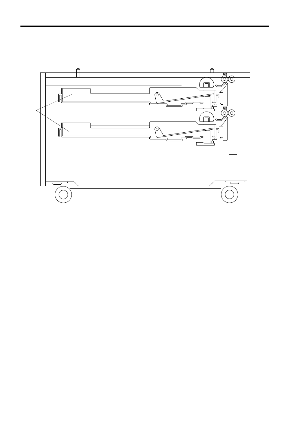
2. COMPONENT LAYOUT
2.1 MECHANICAL COMPONENT LAYOUT
1
5
2
4
1. Paper Tray 1
2. Paper Feed Rollers
3. Relay Rollers
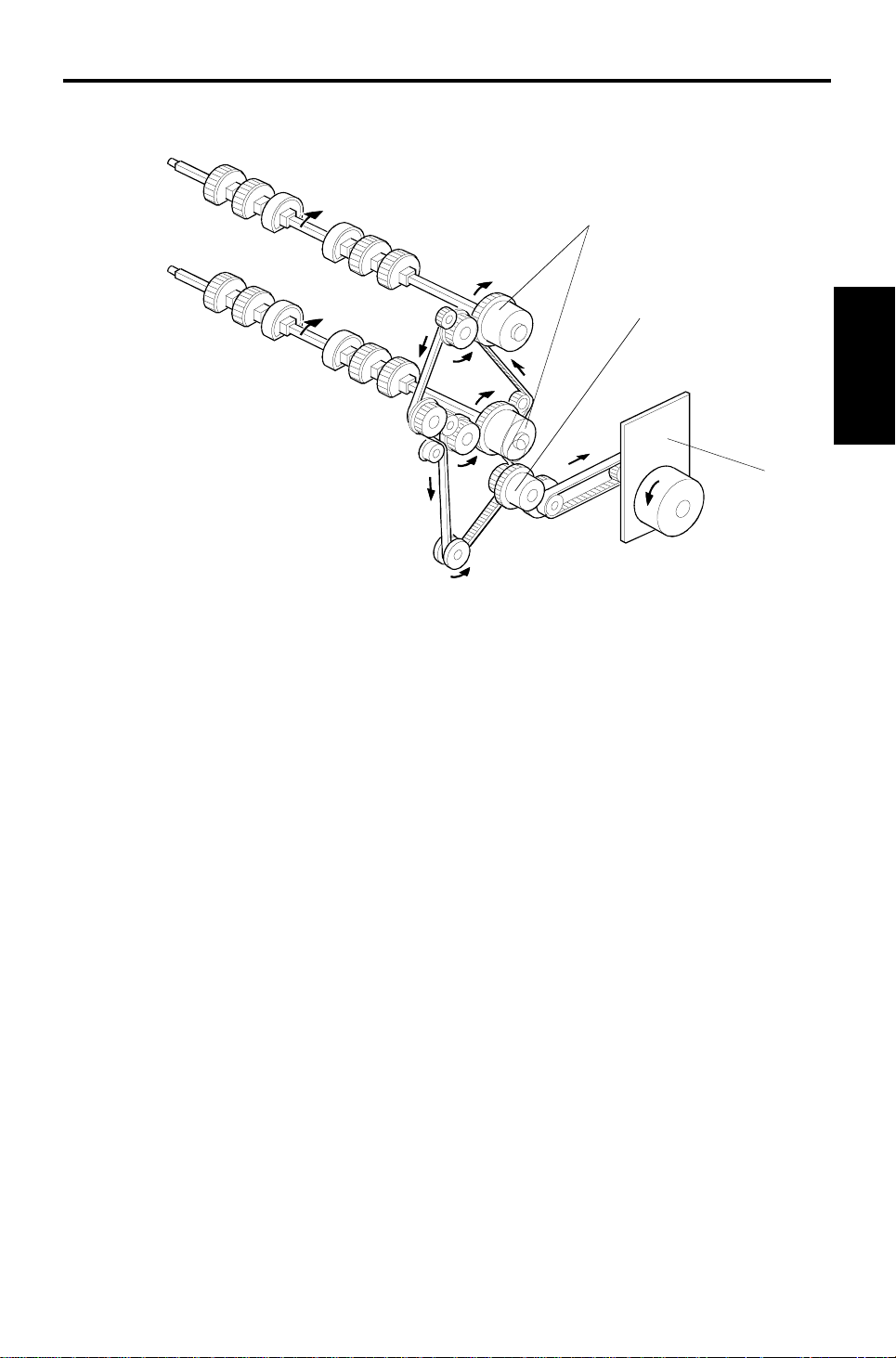
2.2 DRIVE LAYOUT
4. Lower Right Door
5. Paper Tray 2
1
3
1
5
4
1. Vertical Transport Roller Gears
2. Paper Feed Clutch 1
3. Paper Feed Clutch 2
4. Main Motor
5. Relay Clutch
2
Page 4

13th January 1995 COMPONENT LAYOUT
2.3 ELECTRICAL COMPONENT DESCRI P TI ON
Refer to the electrical compone nt layou t on the reverse side of the Poin t to
Point Diagram (on waterproof paper).
Symbol Index No. Description Note
Motors
M1 4 Main Drives all the paper tray components
Circuit board
PCB1 1 Interface board
Sensors
S1 2 Tray set 1
S2 3 Tray set 2
S3 10 Relay 1 Detects when the leading edge of the paper
S4 11 Relay 2
S5 5 Paper end 1
S6 6 Paper end 2
Switches
SW1 12 Tray cover
Clutches
CL1 7 Paper feed 1
CL2 8 Paper feed 2
CL3 9 Relay Drives the rollers in the paper trays
Heaters
H1 13 Tray (Option) Turns on when the main switch is off, to keep
H2 14 Tray (Option)
Controls the paper feed tray unit in response
to signals from the copier
Detects whether the paper tray is in place
leaves the paper tray, to determine copier
relay clutch timing and jam detection timing
Detects when the paper tray runs out of paper
Detects whether the tray unit cover is open,
and cuts the 24 Vdc line if it is.
Starts to feed paper from the tray
the paper in the trays dry
(A553)
Paper Tray Unit
3
Page 5
OVERVIEW 13th January 1995
3. OVERVIEW
[A]
This paper feed unit is a two-tray type . Ea ch pape r tray [A] is a drawer type
that can hold up to 250 sheets of paper.
The paper feed mechanism uses a corner separator system. The funct ion of
the system is exactly the same as for the ma in mach ine excep t that there is
no paper size detection. The pape r size for e ach paper tray is input at the
operation panel, either by the technician or by the user.
All the electrical components of the paper tray are controlled by the copier
main board through the tray interface board.
4
Page 6
13th January 1995 DRIVE MECHANISM
4. DRIVE MECHANISM
[C]
[B]
[A]
(A553)
Paper Tray Unit
All the tray rollers are driven by the main motor [A] via timing belt s, clut che s
and a train of gears.
The main motor and the relay clutch [B ] are ene rgize d at the same time as
the Start key is pressed.
The paper feed clutch [C] is energized 300 ms after the main motor starts to
rotate. When th e pa pe r fee d clut ch for the selected paper tray is energized,
paper is fed from the paper tray to the main frame through the relay rollers.
5
Page 7

PAPER FEED AND MISFEED DETECTION TIMING 13th January 1995
5. PAPER FEED AND MISFEED DETECTION
TIMING
A4 Sideways. Lower Paper Feed Station 200 mm/s
J1 and J2: Checks whether the sensor is activeted within 667 ms after
the designeted time for these sensor.
6
Page 8

13th January 1995 INSTALLATION
6. INSTALLATION
6.1 ACCESSORY CHECK
Check the quantity and cond itio n of the accessories in the box against the
following list:
1. Right Support Bracket ...........................................................1
2. Left Support Bracket...............................................................1
3. Joint Bracket...........................................................................1
4. Shoulder Screw .....................................................................1
5. Screw - M4 x 8............... .. .......... .......... .. .......... .......... .. .......... .4
6. New Equipment Condition Report..........................................1
7. Installation Procedure ...........................................................1
(A553)
Paper Tray Unit
7
Page 9

INSTALLATION 13th January 1995
6.2 INSTALLATION PROCEDURE
[A]
CAUTION
!
Unplug the copier power cord before starting the fol low ing proc edur e.
NOTE: Keep the shipping retainers after inst alling the machine. They will be
reused if the machine is transported to another location in the future.
Proper reinstallation of th e ship ping retainers is required in order t o avo id any
transport damage.
1. Remove the strips of tape.
2. Remove the bottom plate stopper [A].
8
Page 10

[J]
13th January 1995 INSTALLATION
[B]
[F]
[I]
[D]
[H]
[D]
[C]
For copiers with an LCT unit: Do not
lift the copier by holding the LCT unit.
[G]
[E]
[K]
3. Set the copier [B] on th e pa pe r tray un it [C]. Align the 2 pins [D] on the
paper tray unit with the holes in the base pla te of the cop ier.
(A553)
Paper Tray Unit
4. Open the lower right door [E] and eith er the LCT [F] or the upper right
door [F] (depending on the type of copier).
5. Secure the copier to the pape r tra y unit with the joint bracket [G] .
6. Connect the cable [H] an d op tic fib er [I].
7. Attach the support bracke ts [J] to the bottom of the pap er tray unit as
shown (4 screws).
CAUTION
!
If you do not do this, the machine may fall forwards if all the paper
trays are pulled open.
8. Pull out the paper tray and load paper into it. (The pap er size an d
direction for each tray should be desig nated by a customer.)
NOTE: The side and rear fences should be pro pe rly positioned.
9. Turn on the main switch.
10. Enter the prope r pap er size for each paper tray by follo wing the
instructions in the copier’s man ual .
11. Attach the appropriate tray decals [K] which are included in the accessory
box of the main copier.
12. Check the machine’s o pe rat ion and copy quality.
9
Page 11

INSTALLATION 13th January 1995
6.3 TRAY HEATER (OPTION)
[E]
[D]
[B]
[A]
[G]
[F]
[C]
1. Remove the rear cover [A].
2. Remove the second pape r t ray [B ] (2 screws) an d th e lower front cover
[C] (2 screws).
3. Install the tray heaters [D] (2 screws each).
4. Install the clamper [E ] an d clamp the hea te r h arn esses.
5. Install the heater bracket [F] (2 screws).
6. Connect the heater harnesses.
7. Install the clamper [G ] an d clamp the hea te r h arn esses.
NOTE: Afte r re pla cing the paper tra y, pe rfo rm t he sid e-t o-sid e registration
adjustment (see the Removal and Adjustment section of the manual
for the copier).
10
Page 12

13th January 1995 SERVICE TABLES
7. SERVICE TABLES
7.1 DIP SWITCHES
DIP SW 101
1234567 Function
Off------Speed in the free run mode: 200 mm/s
On------Speed in the free run mode: 150 mm/s
-OnOff----Bank type : 500 sheet type
-OffOn----Bank type : 250 sheet type
Normal Operation / Free Run Mode 1*:
---OffOn--
- - - On Off - -
---OnOn--
-----OnOffFree Run Mode 2
-----OnOnFree Run Mode 1
One paper feed tray type
Free Run Mode 2*: Paper feed tray 1 only
Normal Operation / Free Run Mode 1*:
Two paper feed tray type
Free Run Mode 2*: Paper feed tray 2 only
Normal Operation / Free Run Mode 1*:
Three paper feed tray type
Free Run Mode 2*: Paper feed tray 3 only
(A553)
Paper Tray Unit
Do not touch dip switches 1 to 5.
How to do a free run
1. Select either mode 1 or mode 2 with dip switches 6 and 7.
2. Turn off the power, disconnect the optical cable, and turn on the power.
3. Press SW101 on the PCB to sta rt th e free run.
4. When you wish to stop the free ru n, press SW102 on the PCB, then reset
the dip switches to their default set tin gs.
Free Run Mode 1
The paper feed operation perfo rms up to 20 times fo r each pa per f eed sta tion.
(10 s) (10 s) (10 s)
1st feed station 2nd feed station 3rd feed station
Repeat Two paper feed tray type
Repeat Three paper feed tray type
Free Run Mode 2
The paper feed operation can be checked for the sele cted paper feed station.
11
Page 13

SERVICE TABLES 13th January 1995
7.2 TEST POINTS
NUMBER FUNCTION
TP101 + 5V
TP102 + 24V
TP103 GND
TP104 TXD (Transmit signal)
TP105 RXD (Receive signal)
TP106 GND
12
Page 14

13th January 1995 REPLACEMENT AND ADJUSTMENT
8. REPLACEMENT AND ADJUSTMENT
8.1 EXTERIOR COVE R REMO VAL
[E]
[B]
Rear Cover [A]: (2 screws)
Front Lower Cover [B]:
1. Slide out the cassett es.
2. Remove the front lower cove r (2 screws).
[A]
(A553)
Paper Tray Unit
[D]
[C]
Right Front Cover [C]:
1. Remove the front lower cove r [B] .
2. Remove the right front cover (2 screws).
Right Rear Cover [D]:
1. Remove the rear cover [A ].
2. Remove the right rear cover (2 screws).
Left Cover [E]:
1. Remove the rear cover [A ].
2. Remove the front lower cove r [B] .
3. Remove the left cover (4 screws).
13
Page 15

[A]
REPLACEMENT AND ADJUSTMENT 13th January 1995
8.2 MAIN MOTOR REPLACEMENT
[E]
[B]
[C]
[D]
1. Remove the rear cover (see Exte rior Cover Removal).
2. Remove the link bracket [A] (2 screws).
3. Remove the main motor bracke t assembly [B] (2 screws, 2 connectors).
4. Remove the spring [C].
5. Remove the main motor [D] (4 screws, 1 clip, 1 gear).
NOTE: When rein stalling the main motor assembly, make sure that the relay
clutch stopper groove eng ag es with the st oppe r [ E] on th e main
motor bracket.
14
Page 16

13th January 1995 REPLACEMENT AND ADJUSTMENT
8.3 CLUTCH REPLACEMENT
[B]
[A]
[F]
[D]
[C]
[E]
First Paper Feed Clutch
1. Remove the rear cover (see Exte rior Cover Removal).
(A553)
Paper Tray Unit
2. Remove the bracket [A] (2 screws).
3. Remove the first paper feed clutch [B] (1 conn ect or).
Second Paper Feed Clutch
1. Remove the rear cover (see Exte rior Cover Removal).
2. Remove the link bracket [C] (2 screws).
3. Remove the bracket [D] (2 screws)
4. Remove the second paper feed clutch [E] (1 connect or).
Relay Clutch
1. Remove the rear cover (see Exte rior Cover Removal).
2. Remove the link bracket [C] (2 screws).
3. Remove the main motor bracke t assemlby (see Main Motor Replacemen t).
4. Remove the relay clutch [F] (1 con ne cto r).
NOTE: When you re inst all a clutch, make sure that the clut ch stopper groove
engages the clutch stopper.
15
Page 17

[D]
[a]
REPLACEMENT AND ADJUSTMENT 13th January 1995
8.4 FEED ROLLER REPLACEMENT
[B]
[C]
[A]
[a]
[b]
[c]
[c]
[b]
1. Remove the paper feed tray [A ] (2 screws).
2. Remove the stopper bracket [B] (1 screw).
3. Remove the feed roller assembly [C].
4. Remove the feed roller [D].
NOTE: • When installing the fe ed roller assembly, the flat side of the
roller should be facing down.
• The two rollers without rubber should be at the center positio n
of the shaft.
• The normal roller position is [a].
• There are two extra roller positions: for A size paper/ LT size
paper [b] and B size paper [c]. When paper jam an d non-f ee d
errors occur, change the fe ed roller po sitio n.
• After reinstalling the paper tray, perf orm the side-to
side-registration adju stment (see Removal and Adjustmen t in
the manual for the copier).
16
Page 18

[B]
13th January 1995 REPLACEMENT AND ADJUSTMENT
8.5 RELAY SENSOR REPLACE MENT
(A553)
[A]
Paper Tray Unit
[C]
1. Remove the rear cover (see Exterior Cover Removal).
2. Remove the rear right cover (see Exterior Cover Removal).
3. Remove the vertical transpo rt un it [A ] (2 screws).
4. Remove the vertical transport guide [B] (4 screws).
5. Remove the relay sensors [C] (1 connector each).
17
Page 19

 Loading...