

Page 1

AUTO REVERSE
DOCUMENT FEEDER
(Machine Code: A548)
Page 2

13th January 1995 SPECIFICATIONS
1. SPECIFICATIONS
Original Size and Weight: Thick original mode (default mode )
Use this setting for norma l paper types
Maximum A3, 11" x 17"
Minimum B6 (sideways), 51/2" x 81/2"
Weight 52 ~ 128 g/m2 (14 ~ 34 lb)
Thin original mode
Maximum A3, 11" x 17"
Minimum B6, 51/2" x 81/2"
Weight 40 ~ 128 g/m2 (11 ~ 34 lb)
Auto reverse mode
Maximum A3, 11" x 17"
Minimum B5, 51/2" x 81/2"
Weight 52 ~ 105 (14 ~ 27 lb)
Original Feed: Automatic feed - ADF mode
Manual feed one by one - SADF mode
Auto Reverse Feed - ARDF mode
Document
Auto Reverse
Original Table Capacity: 50 sheets at 80 g/m2 (21 lb)
Original Placement: Face up, first sheet on top
Original Separation: Feed Roller and Friction Belt
Original Transport: One flat belt
Power Consumption: 45 W
Power Source:
Dimensions (W x D x H): 610 x 507 x 130 mm (24.0" x 20.0" x 5.1")
Weight: Approximately 10.5 kg (23.2 lb)
24 V ± 10% from the copier, 1.8 A
1
Page 3
10
5
COMPONENT LAYOUT 13th January 1995
2. COMPONENT LAYOUT
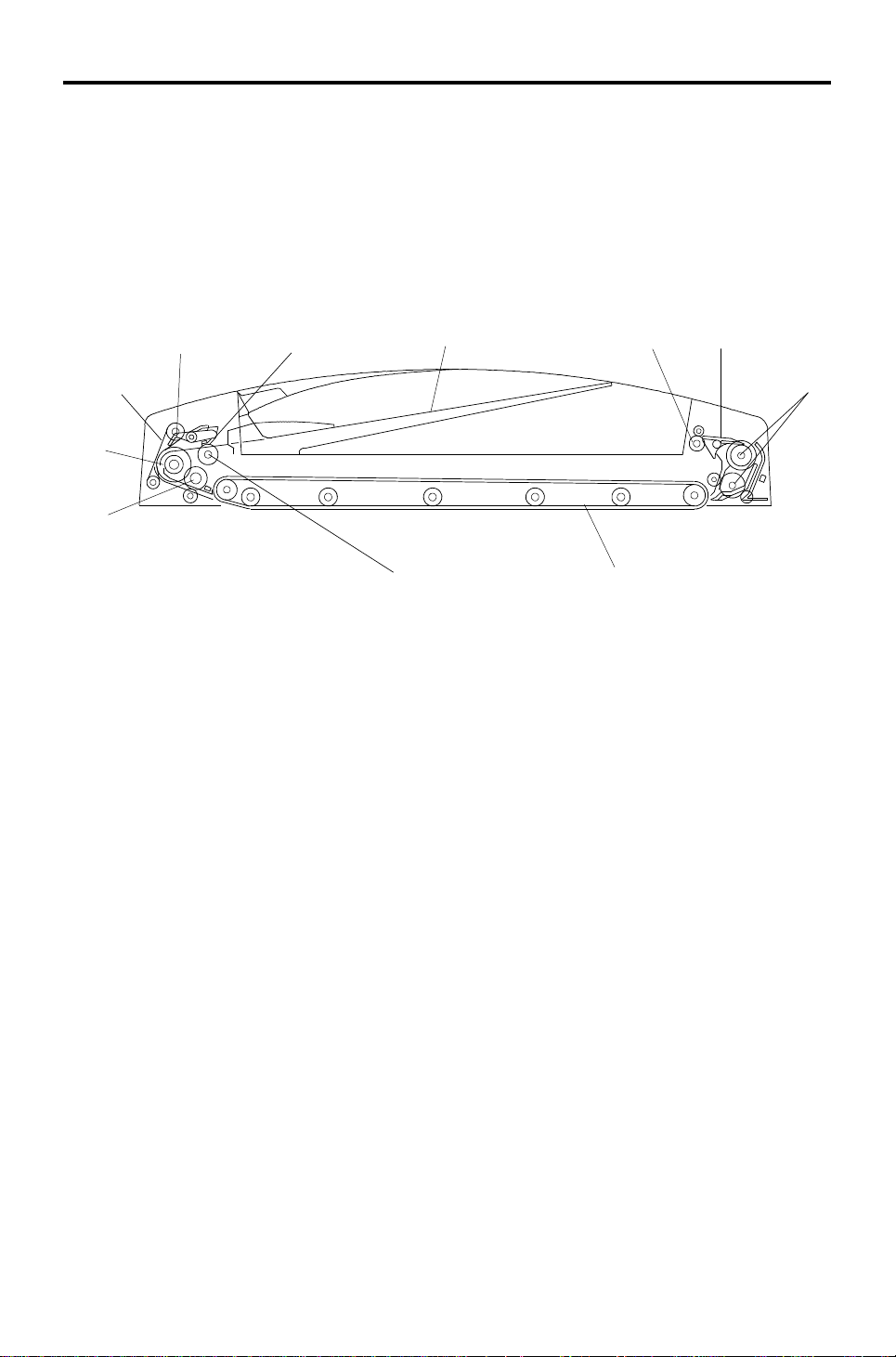
2.1 MECHANICAL COMPONENTS
1
11
9
1. Original Stopper
2. Press Lever
3. Original Table
4. Exit Rollers
5. Inverter Pawls
2
8
7. Transport Belt
8. Pick-up Rollers
9. Pull-out Roller
10. Feed Roller
11. Friction Belt
43
6
7
6. Inverter Rollers
2
Page 4
4
13th January 1995 COMPONENT LAYOUT
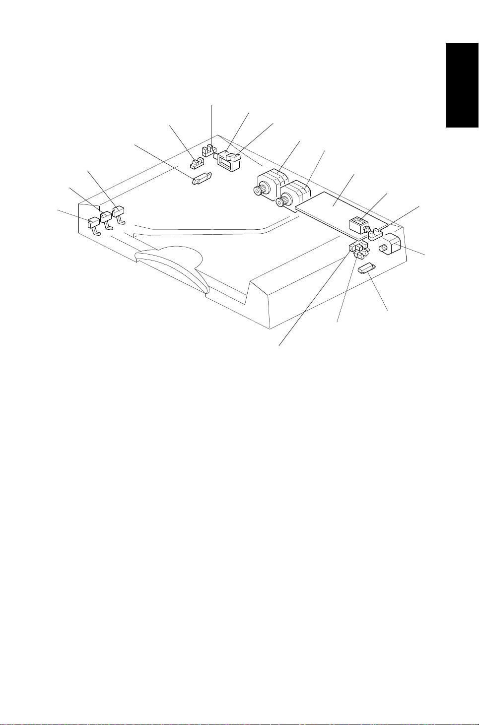
2.2 ELECTRICAL COMPONENTS
17
16
15
14
1. Original Set Sensor
2
1
3
Document
Auto Reverse
5
6
7
8
9
10
11
12
13
10 Feed-out Motor
2. Feed-in Cover Open Sensor
3. Stopper Solen oid
4. Indicator Panel Lamps
5. Feed-in Motor
6. Belt Drive Motor
7. DF Main Board
8. Inverter Solenoid
9. Feed-out Cover Open Sensor
11. Feed-out Sen s or
12. APS Start Sensor
13. DF Position Sensor
14. Original Width Sensor - 1
15. Original Width Sensor - 2
16. Original Width Sensor - 3
17. Registration Sensor
3
Page 5

ELECTRICAL COMPONENT DESCRIPTION 13th January 1995
3. ELECTRICAL COMPONENT DESCRIPTION
Symbol Name Function Index No.
Motors
M1 Feed-in
M2 Belt Drive Drives the transport belt 6
M3 Feed-out
Sensors
S1 Original Set
S2 Feed-in Cover Open
S3 Feed-out Cover Open
S4 Feed-out
S5 APS Start
S6 DF Position
S7 Original Width-1 Detects the width of the original 14
S8 Original Width-2 Detects the width of the original 15
S9 Original Width-3 Detects the width of the original 16
S10 Registration
Solenoids
SOL1 Stopper
SOL2 Inverter
PCB
PCB1 DF Main Board Controls all DF functions 7
Indicators (Lamps)
L1 Ready
L2 Auto
Drives the feed-in system (pick-up, feed
and pull-out rollers, separation belt)
Drives the feed-out and the inverter
system
Detects whether originals have been
placed on the original table
Informs whether the feed-in cover is open
or not
Informs whether the feed-out cover is
open or not
Checks for original misfeeds and
determines original stop timing when in
auto-reverse mode
Informs the CPU that it is time to detect
the original size (in platen mode)
Informs the CPU whether the DF is in the
up or down position
Determines original stop timing and
measures the length of the original
Lifts the original stopper and lowers the
feed-in lever to feed the set of originals to
the feed roller
Energizes to invert the original when
copying two-sided originals
Informs the operator that the DF is in the
down position.
Informs the operator that the auto feed
mode is available.
5
10
1
2
9
11
12
13
17
3
8
4
4
4
Page 6
[F]
[C]
13th January 1995 DETAILED DESCRIPTIONS
4. DETAILED DESCRIPTIONS
4.1 ORIGINAL PICK-UP ME CHANI SM
[B]
[D]
[A]
[E]
Document
Auto Reverse
When an original is placed on th e table, the leading edge is sto pp ed by t he
stopper [A], and the feeler activates the original set sensor [B]. The Insert
Original indicator light goes out an d the DF informs the copie r’s CPU that th e
originals have been set.
When the Print key is pressed, the stopper solenoid [C] activates to raise the
stopper to allow the originals to be fed in, and to lower the press lever [D] to
press the originals against the pick-up rollers [E ].
An anti-static brush [F] is insta lled to elimin at e static electricity caused during
the original pick-up process.
5
Page 7
[E]
DETAILED DESCRIPTIONS 13th January 1995
4.2 SEPARATION AND PAPER FE ED ME CHANI SM
[D]
[A]
[E]
[B] [F]
[C]
[D]
[A]
[B]
Originals are separated using the frictio n belt [A] and the feed roller [B].
When the copier sends a signal to the DF to feed in the original, the feed-in
motor [C] starts rotating (clockwise) to drive the pick-u p [D], fe ed and pull-o ut
[E] rollers. A one-way bearing stops the friction belt from rot ating . Originals
are separated and fed in one by one because the resist an ce of the stat ionary
friction belt is greater than the friction betwee n pages of th e origina l.
When the registration sensor [F] detects the separated first origin al, the
feed-in motor reverses (counter clockwise), and the drive is transmitted only
to the pull-out rollers due to a one-way bearing. In this condition, the pull-ou t
rollers are still rotating in the same direction, and they feed the original to the
exposure glass. The motor turns off when the trailing edg e of the 1st orig inal
has finished passing over th e sensor.
To prepare the next original, the feed-in motor turns clockwise to separate
the second original and the motor turns off when the registration sensor
detects the second origina l. Whe n it is time fo r the secon d orig inal to be fed
to the exposure glass, the feed -in mot or tu rns cou nt er clockwise .
6
Page 8
13th January 1995 DETAILED DESCRIPTIONS
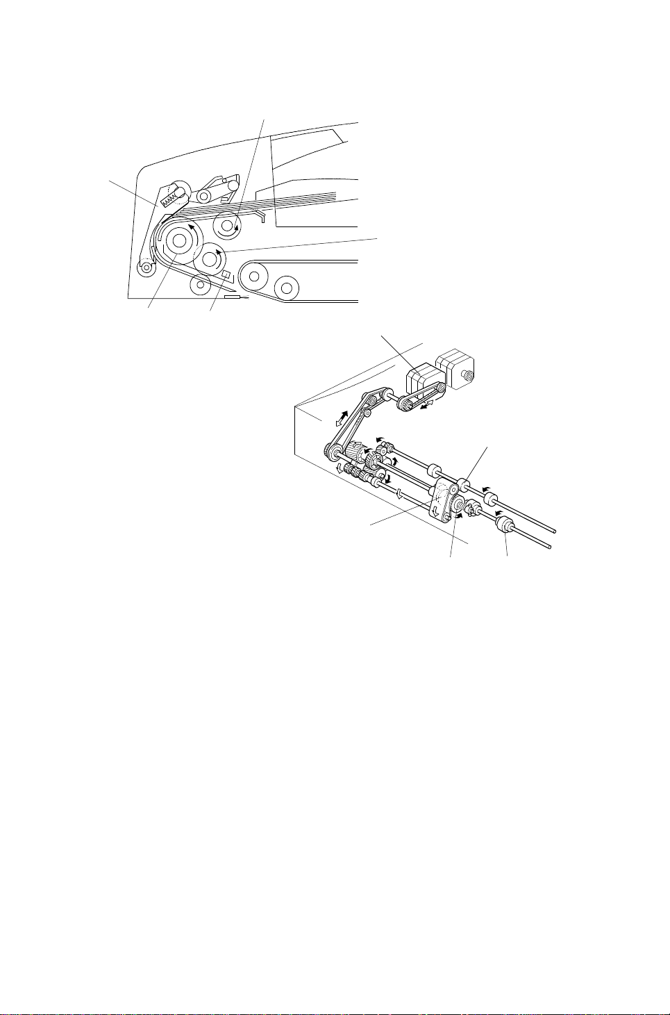
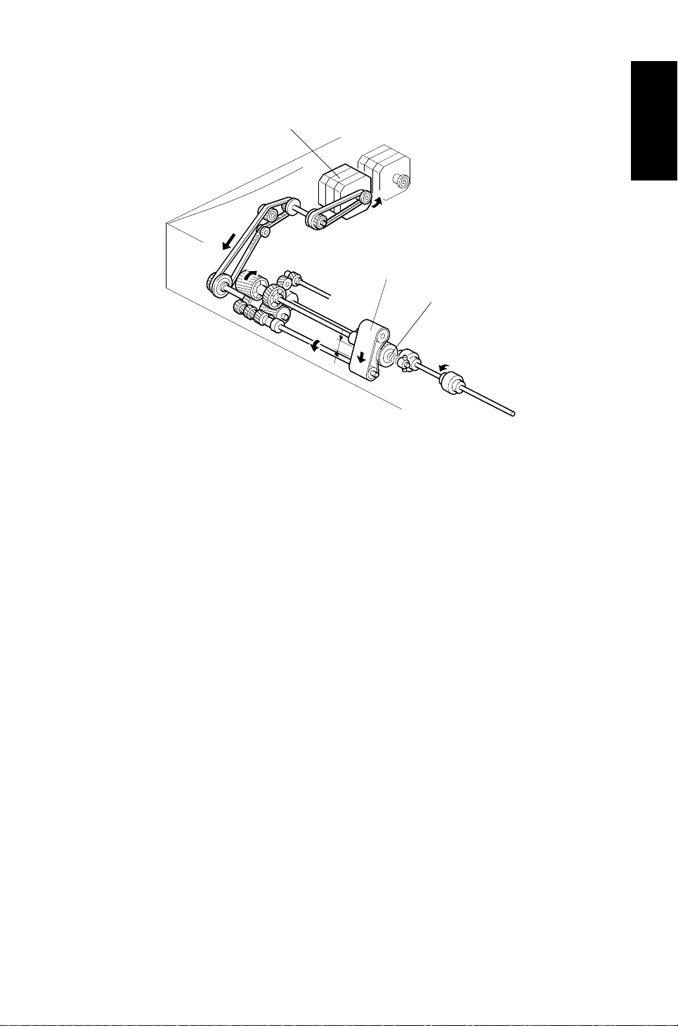
4.3 FRICTION BELT DRIVE MECHANISM
[A]
[B]
[C]
Document
Auto Reverse
The feed-in motor [A] drives the frictio n belt [B] through timing belts and
gears. The one-way bearing allows the belt to rotate in the dire ctio n sho wn
only when the feed-in motor is rotating count erclo ckwise. (The feed -in mot or
rotates counterclockwise when the original is passing over the registration
sensor, and only the pull-out rollers are rotatin g to feed the pape r to the
exposure glass.)
As a result of this operation, th e part of the friction belt that contacts the feed
roller [C] or the original changes. This prevents multiple feeding or causing
originals to become dirty.
The reverse movement of the frictio n be lt will not aff ect the next origin al
because the pressure of the press leve r hold s the origin als in pla ce.
7
Page 9
DETAILED DESCRIPTIONS 13th January 1995
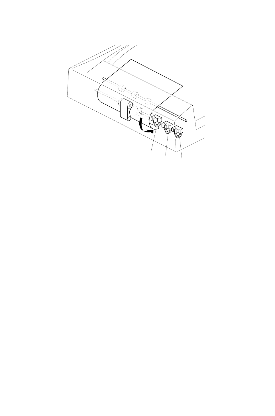
4.4 ORIGINAL SIZE DETE CTION
[C]
[B]
[A]
The DF detects original width using three original width sensors-1 [A] , -2 [B ]
and -3 [C]. It also detect s the origin al length using the registra tion sensor.
The DF CPU counts the feed-in mot or’s drive pulse s during the on timing of
the registration senso r. Ba sed on th is pulse coun t, the CPU det ermin es the
original length.
The machine detects t he origin al size by th e total combination of all fo ur
sensors.
8
Page 10

Rear Scale
13th January 1995 DETAILED DESCRIPTIONS
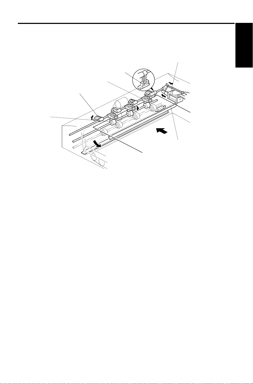
4.5 PAPER TRANSPORT MECHANISM
[B]
Document
Auto Reverse
[C]
[A]
Left Scale
3.5 mm
Original
The transport belt [A] is driven by an in depe nd en t motor called the belt drive
motor [B] (a dc stepper motor). The belt drive motor starts rotating soon after
the copier sends an original feed-in signal.
Inside the transp ort belt are four pressure roller shaft s, which achieve the
proper amount of pressure between the belt and the original. The pressure
roller shaft [C] closest to the left original scale is made of rubber for the
stronger pressure that is required whe n in the thick origin al mode (this is the
mode used for normal paper). The other rollers are spo nge rolle rs.
Since the copier’s original alig nme nt posit ion is at the left rear corner (not in
the center), the originals fed from the DF must also be at this posit ion . But if
the original was to be fed along the rear scale , un ne cessa ry original skew,
jam or wrinkling may occur.
To prevent such proble ms, th e original transfer position is set to 3.5 mm
away from the rear scale as shown. The correct ion for this 3.5 mm gap is
compensated for by the posit ion of the len s unit. (Also see "Horizontal Lens
Positioning" in the Optics section of the manual f or th e copier main body.)
9
Page 11

DETAILED DESCRIPTIONS 13th January 1995
4.6 THICK/THIN ORI GINAL MODES
Fig. 1
7 mm
Fig. 2
[A]
Fig. 3
This document feed er ha s two dif ferent ways of stopping orig ina ls a t th e
correct position on the exposu re gla ss. The technician can select one of
these using a copier SP mo de. The user can also select the mode.
1. Thick Original Mode (Normal Paper Mode)
This mode is the factory set mod e. Th e belt drive motor remains
energized to carry the original approximately 7 mm pass the left scale
(Figures 1 and 2). Then the motor pause s and reverses to feed the
original back against the left scale (Fig. 3). This forces th e orig ina l to hit
against the left original scale [A] and thus aligns the trailing edge to
minimize the original skew on the exposu re gla ss.
2. Thin Original Mode
To protect originals from being damaged by the movements of the
transfer belt, thin orig inal mode can be selected. The belt drive motor
stops shortly after the orig inal trailing edge passes the registrat ion
sensor. This stops the orig inal at the correct position on the expo sure
glass.
10
Page 12

[A]
13th January 1995 DETAILED DESCRIPTIONS
4.7 ORIGINAL FEE D-O UT MECHANISM
[B]
Document
Auto Reverse
When the scanner reaches the return position, the copier’s CPU sends the
feed-out signal to the DF CPU. When the DF receives the feed-out signal, the
belt drive and feed-out motors [A ] tu rn on.
The feed-out sensor [B] installed in the feed -ou t sect ion counts the number of
pulses to calculate how long the fee d-o ut motor must stay on to feed th e
original out of the machine comp letely.
[B]
11
Page 13

DETAILED DESCRIPTIONS 13th January 1995
4.8 TWO-SIDED ORI G INAL FEED MECHANISM
[B]
[A]
Unlike one-sided original feed, the back side of the original must be copied
first to keep the originals and copies in the correct order.
During original feed-in, the sequence is the same as fo r one-side d feed .
However, the belt drive moto r co nt inu es rotating until the original reaches the
inverter section. The DF CPU also energize s t he fee d-o ut mo to r and the
inverter solenoid [A] fo r a short time to lift the inverter pawls [B ].
After the inverter mechanism inverts the original, the be lt drive mo to r
reverses and the original is fed towards the origina l scale. It is stopped at the
correct position on the exposu re gla ss, an d the DF CPU send s the copy sta rt
signal.
When the scanner reaches the return position, the copier’s CPU sends the
invert original signal to the DF CPU in order to make a copy of the front side.
The original is inverted in the same way as for copying the back side , as
explained earlier on this page.
12
Page 14

13
5. TIMING CHARTS
5.1 A4 SIDEWAYS: 1 S I DED O RI GI NAL
13th January 1995 TIMING CHARTS
Auto Reverse
Document
Feeder
Page 15

14
5.2 COMBINE 2 ORIGINAL MO DE
TIMING CHARTS 13th January 1995
Page 16

15
5.3 A4 SIDEWAYS: DUPLE X
13th January 1995 TIMING CHARTS
Auto Reverse
Document
Feeder
Page 17

INSTALLATION 13th January 1995
6. INSTALLATION
6.1 ACCESSORY CHECK
Check the quantity and cond itio n of the accessories in the box against the
following list:
1. New Equipment Condition Report................... .. .. .. ..1
2. Installation Procedure.......... .. ..................................1
3. Stud Screw..............................................................2
4. Philips Screw with Flat Washer – M4 x 10..............2
5. Sponge Retainer......................................................1
16
Page 18

[A]
[H]
13th January 1995 INSTALLATION
6.2 INSTALLATION PROCEDURE
[A]
[B]
Document
Auto Reverse
[E]
[D]
[F]
[C]
CAUTION
!
Unplug the copier power cord before starting the fol low ing proc edur e.
1. Remove the strips of tape [A].
2. Attach the sponge retainer [B] to the top cover of the copier as shown.
3. Tighten the two stud screws [C].
[E]
[I]
[G]
4. Mount the ARDF by aligning the holes [D] in the ARDF and the stud
screws [C], then slide the ARDF to the front as shown.
NOTE: When mounting the ARDF, hold it by hand as shown in the
illustration. Holding it in another way may da mag e the ARDF.
5. Screw the two M4 x 10 screws [E] into the holes [F] and tight en the m.
6. Connect the connectors [G ] into the socket on the rear of the copier.
7. All models except for the A156: Attach the symbol explana tio n de cal
[H] and the combine origin als explanation decal [I] to th e ARDF as shown.
17
Page 19

SERVICE TABLES 13th January 1995
7. SERVICE TABLES
7.1 DIP SWITCHES
DPS 101
1 234
0 0 0 0 Normal setting
1 0 0 0 One-sided thin original mode free run with paper (35 cpm)
0100
1100
0 0 1 0 Two-sided mode free run with paper (35 cpm)
1 0 1 0 Two-sided mode free run without paper (35 cpm)
1 0 0 1 One-sided thin original mode free run with paper (25 cpm)
0101
0 0 1 1 Two-sided mode free run with paper (25 cpm)
1 0 1 1 Not used
1 1 0 1 Solenoid test
0 1 1 0 Motor test
1 1 1 0 Combine two originals mode free run with paper
0 0 0 1 Not used
0 1 1 1 Not used
1 1 1 1 Indicators On
One-sided thick original mode (normal mode) free run with
paper (35 cpm)
One-sided thick original mode (normal mode) fee run without
paper (35 cpm)
One-sided thick original mode (normal mode) free run with
paper (25 cpm)
Function
NOTE: a) Paper will automatically feed after 3 seco nd s when the "with
paper" free run modes are selected.
b) To prevent the friction belt from wearing, open the feed-in cover
when performing the "without paper" free ru n mod es.
c) The normal copying speed is 35 cpm for the A153/ 15 5/ 156, and
27 cpm for the A157/159/160.
To make a free run
1. Set up dip switches 1 to 4 for the required free run mod e th e test be gin s
automatically.
2. To stop the free run, put the dip switches back to 0.
18
Page 20

13th January 1995 SERVICE TABLES
7.2 VARIABLE RESISTORS
VR No. Function
101
102
Adjusts the registration in one-sided thin original
mode.
Adjusts the registration in two-sided original
mode.
7.3 LED
LED No. Function
101 Monitors the communication with the copier.
7.4 FUSE
Document
Auto Reverse
FUSE No. Function
101 Protects the 24 V line.
19
Page 21

REPLACEMENT AND ADJUSTMENT 13th January 1995
8. REPLACEMENT AND ADJUSTMENT
8.1 TRANSPORT BELT REPLACEMEN T
[A]
[B]
[C]
[E]
[D]
1. Turn off the main switch and lift up the DF.
2. Remove the grip [A] (3 screws).
3. Remove the 6 screws securing the transport belt assembly [B].
NOTE: Remove the two lower screws [C] first.
4. Bend the transport belt assembly and pull out the transport belt [D] as
shown.
NOTE: a) When installing the tra nsport belt, make sure that the belt runs
under the belt gu ide sp ace rs [ E] .
b) When securing the transpo rt belt assembly with the 6 screws,
make sure to secure the four uppe r screws f irst.
20
Page 22

[D]
[C]
13th January 1995 REPLACEMENT AND ADJUSTMENT
8.2 FEED ROLLER REPLACEMENT
[B]
[A]
Document
Auto Reverse
1. Turn off the main switch and open the feed-in cover [A ].
2. Remove the feed roller assembly [B] by pullin g it to ward s t he fron t.
3. Replace the feed roller.
NOTE: When installing the feed roller assembly, make sure the pins [C, D]
on both sides are fixed properly.
21
Page 23

REPLACEMENT AND ADJUSTMENT 13th January 1995
8.3 FRICTION BELT REPLACEME NT
[B]
[A]
[C]
1. Turn off the main switch and open the feed-in cover [A ].
2. Gently pull up the friction belt assemb ly [B] and remove it from the shaft.
3. Replace the friction belt [C].
22
Page 24

[C]
[F]
[H]
13th January 1995 REPLACEMENT AND ADJUSTMENT
8.4 ORIGINAL SE T AND ORI G INAL WIDTH SENSOR
REPLACEMENT
[A]
Document
Auto Reverse
[B]
[G]
[D]
[E]
1. Turn off the main switch.
2. Remove the upper cover [A] (7 screws).
3. Remove the pick-up solenoid spring [B].
4. Remove the stopper/pressure lever shaft [C] (2 E-rings).
5. Remove both front [D] and rear [E] feed-in cover magnet catches (1
screw each).
6. Remove the feed-in guide plate [F] (4 screws).
7. Remove the original set sensor assembly [G] (1 screw).
8. Remove the original width sensor asse mbly [H] (1 scre w).
9. Replace the required sen sor.
23
Page 25

REPLACEMENT AND ADJUSTMENT 13th January 1995
8.5 VERTICAL REGISTRATIO N ADJUS TMENT
8.5.1 One Sided Thin Original Mode
Note:
• After replacing the DF main boa rd, always do the Rough Ad justment
using VR101 first. Then do the Fin e Ad just ment procedure.
• At other times, just do the Fine Adjustment procedure.
• After finishing the adjustment, be sure to turn off the dip switch.
[B]
[C]
[A]
- Rough Adjustment (Using VR101) -
1. Remove the small cover [A] at the rear of the DF uppe r cover (1 screw).
2. Turn on dip switch 101-1 [B].
3. Place a sheet of A4/81/2" x 11" sideways paper (64 g/m2, 17 lb) on the
original table. (The paper will feed automat ically. )
4. After the original stop s on th e exp osure glass, raise the DF carefully so
that the original doe s not mo ve.
5. Check that the gap bet ween the trailing edge of the pap e r an d th e left
original scale [B] is 0 ± 2.5 mm .
6. If the gap is not within this specification, adju st th e reg istra tio n with
VR101 [C]. (Turning VR10 1 counter-clockwise will increase the gap. )
- Fine Adjustment (Using a Copier SP Mode) -
1. Perform steps 1 through 5 of th e rough adjustment procedu re.
2. If the gap is larger than 2.5 mm, adjust the registration with the copier SP
mode for the DF Registration Adju stment in one-sided original mode .
(Increasing the set ting will increase the gap.)
24
Page 26

13th January 1995 REPLACEMENT AND ADJUSTMENT
8.5.2 Two Sided Original Mode
Note:
• After replacing the DF main boa rd, always do the Rough Ad justment
using VR102 first. Then do the Fin e Ad just ment procedure.
• At other times, just do the Fine Adjustment procedure.
• After finishing the adjustment, be sure to turn off the dip switch.
[C]
[B]
[A]
Document
Auto Reverse
- Rough Adjustment (Using VR102) -
1. Remove the copier’s left original scale (2 screws).
2. Remove the small cover [A] at the rear of the DF uppe r cover (1 screw).
3. Turn on dip switch 101-3 [B].
4. Place a sheet of A4/81/2" x 11" sideways paper (64 g/m2, 17 lb) on the
original table. (The paper will feed automat ically. )
5. After the original stop s on th e exp osure glass, raise the DF carefully so
that the original doe s not mo ve.
6. Check that the gap bet ween the trailing edge of the pap e r an d th e left
edge of the original rear scale is 10 ± 2 mm.
7. If the gap is not within this specification, adju st th e reg istra tio n with
VR102 [C]. (Turning VR10 2 counter-clockwise will increase the gap. )
- Fine Adjustment (Using a Copier SP Mode) -
1. Perform steps 1 through 6 of th e rough adjustment procedu re.
2. If the gap is not within specif ication, adjust the registrat ion with the copier
SP mode for the DF Registration Adjustmen t in two -side d orig ina l mode .
(Increasing the set ting will increase the gap.)
25
Page 27

REPLACEMENT AND ADJUSTMENT 13th January 1995
8.6 SIDE-TO-S IDE RE GI S TRATI ON (DF PO SI TI O NI NG)
ADJUSTMENT
Note:
• First, adjust the DF side-to-side registration using the cop ier SP mode for
this (see Replacement and Adju stme nt - Sid e-t o-side Registration
Adjusment in the cop ier man ua l).
• Do the following adjustment only when the registrat ion cann ot be broug ht
within the specification (0 ± 2 mm) usin g th e ab ove mentioned SP mode.
SPECIFICATION (Original posit ion from the rear scale)
Thick (Normal) Paper
Original Mode
Thin Original Mode
Two Sided Original Mode
3.5 ± 2 mm (3.5 ± 3 mm for B6 lengthwise)
3.5 ± 2 mm
3.5 ± 3 mm
[A]
1. Place a sheet of A4/81/2" x 11" sideways paper (64 g/m2, 17 lb) on the
original table and press the Prin t key.
2. After the original stop s on th e exp osure glass, raise the DF carefully so
that the original doe s not mo ve.
3. Check if the gap between the re ar ed ge of the paper and the rear origina l
scale is within the specification listed above.
4. If it is out of specification, repositio n th e 2 screws [A] securing the DF
hinge to the long screw hole as shown.
5. Repeat steps 1 to 3.
6. Secure the DF unit at the position where the gap falls wit hin specif ication.
7. Check the copy quality and adjust the ADF side-to-side registration with
the copier SP mode if it is not within the 0 ± 2 mm specification (see
Replacement and Adjustment - Side-to-side Registra tio n Ad jusme nt in
the copier manual).
26
Page 28

 Loading...