

T
Model:
Phoenix II Series
echnical
B
ulletin
Date:
15-Sep-97
No:
PAGE: 1/4
1
Subject:
From:
Service Manual Revision
QAC 1st Field Information Dept.
Classification:
Troubleshooting
Mechanical
Paper path
Other ( )
Part information
Electrical
Transmit/receive
Prepared by:
Action required
Service manual revision
Retrofit information
J.Kasamoto
The lists for SP5-803 (Sensor/Switch Input Signal Data Check) and SP5-804 (Electrical
Component Check) have been changed from the Phoenix Mark Ι series, and this
information was not listed in the insert version service manual. Please add the following
lists to your Phoenix Mark ΙΙ series manual.
The reason for the change is related to the new sorters that can be installed on the Mark ΙΙ
series.
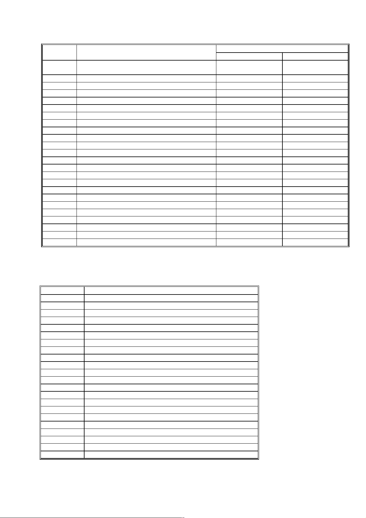
SP5-803 SENSOR/SWITCH INPUT SIGNAL DATA CHECK
3rd level Reading
No Sensor/Switch/Signal 0 1
1 Upper Relay Sensor Paper not detected Paper detected
2 Lower Relay Feed Sensor Paper not detected Paper detected
3 3rd Tray Paper Feed Sensor
(Paper Tray Unit)
4 4th Tray Paper Feed Sensor
(Paper Tray Unit)
5 5th Tray Paper Feed Sensor
(Paper Tray Unit)
6 Registration Sensor Paper not detected Paper detected
7 Fusing Exit Sensor Paper not detected Paper detected
8 By-pass Feed Paper Width Sensor See the Note after the end of this table.
9 By-pass Feed Paper End Sensor Paper detected Paper not detected
10 By-pass Feed Table Switch Table is closed Table is open
11 Upper Tray Paper End Sensor Paper detected Paper not detected
12 Upper Tray Upper Limit Sensor Down Up
13 Not Used - 14 Upper Tray Switch Not set Set
15 Lower Tray Paper End Sensor Paper detected Paper not detected
16 Lower Tray Upper Limit Sensor Down Up
17 Not Used - 18 Lower Tray Switch Not set Set
19 1st Tray Paper End Sensor
(Paper Tray Unit)
20 1st Tray Upper Limit Sensor
(Paper Tray Unit)
21 1st Tray Set Sensor
(Paper Tray Unit)
22 2nd Tray Paper End Sensor
(Paper Tray Unit)
23 2nd Tray Upper Limit Sensor
(Paper Tray Unit)
Paper not detected Paper detected
Paper not detected Paper detected
Paper not detected Paper detected
Paper detected Paper not detected
Down Up
Not set Set
Paper detected Paper not detected
Down Up

T
3rd level Reading
No Sensor/Switch/Signal 0 1
24 2nd Tray Set Sensor
(Paper Tray Unit)
25 3rd Tray Paper End Sensor
(Paper Tray Unit)
26 3rd Tray Upper Limit Sensor
(Paper Tray Unit)
27 3rd Tray Set Sensor
(Paper Tray Unit)
28 LCT Paper End Sensor Paper detected Paper not detected
29 LCT Upper Limit Sensor Off On
30 LCT Lower Limit Sensor Off On
31 LCT Connector Not connected Connected
32 LCT Tray Down Switch Off On
33 LCT Cover Switch Cover closed Cover open
34 Original Length Sensor 2 Off On
35 Original Length Sensor 3 Off On
36 Original Length Sensor 4 Off On
37 Original Width Sensor 5 Off On
38 Original Width Sensor 6 Off On
39 Original Width Sensor 7 Off On
40 Scanner H.P. Sensor Off On
41 Lens Horizontal H.P. Sensor Off On
42 Lens Vertical H.P. Sensor Off On
43 3rd Scanner H.P. Sensor Off On
44 Optics Thermistor Off On
45 Platen Cover Close Sensor Platen cover open Platen cover closed
46 Platen Cover Open Sensor Platen cover closed Platen cover open
47 Vertical Guide Set Switch Vertical guide closed Vertical guide open
48 Paper Exit Cover Switch Paper exit cover
49 Front Cover Switch Front cover closed Front cover open
50 Sorter Entrance Sensor (A556/A557) Off On
51 Sorter Bin H.P. Sensor (A556/A557) Off On
52 Sorter Bin Lift Sensor (A556/A557) Off On
53 Sorter Cover Switch (A556/A557) Cover closed Cover open
54 Sorter Entrance Sensor (A664) Off On
55 Sorter Proof Exit Sensor (A664) Off On
56 Sornter Bin (Jam) Sensor (A664/A658/A555) Off On
57 Sorter Bin (Jam) Sensor (A664/A658/A555) Off On
58 Sorter Bin Home Position Sensor
(A664/A658/A555)
59 Sorter Wheel Sensor (A664/A658/A555) Off On
60 Sorter Bin Rear Plate Open Sensor (A664) Off On
61 Sorter Bin Rear Plate H.P. Sensor (A664) Off On
62 Sorter Jogger H.P. Sensor (A664/A658/A555) Off On
63 Sorter Grip H.P. Sensor (A664/A658/A555) Off On
64 Sorter Staple Hammer H.P. Sensor (A664) Off On
65 Sorter Staple Unit H.P. Sensor (A664/A658/A555) Off On
66 Sorter Staple End Sensor (A664/A658/A555) Off On
67 Sorter Stapler Paper Sensor (A664/A658/A555) Off On
68 Sorter Door Safety Switch (A664/A658/A555) Off On
69 Sorter Transposrt Motor Encoder (A664) Off On
70 Sorter Cartridge Set Switch (A664) Off On
71 Sorter Staple Unit Set Switch (A664) Off On
echnical
B
ulletin
Not set Set
Paper detected Paper not detected
Down Up
Not set Set
Paper exit cover
closed
Off On
open
PAGE: 2/4
T
3rd level Reading
No Sensor/Switch/Signal 0 1
72 Sorter Staple Unit Pulled-out Position Sensor
(A664)
73 Duplex Entrance Sensor Off On
74 Duplex Turn Sensor Off On
75 Duplex Paper End Sensor Paper detected Paper not detected
76 Upper Tray Switch Not set Set
77 Duplex Side Fence Jogger H.P. Sensor Off On
78 Duplex End Fence Jogger H.P. Sensor Off On
80 Main Motor Lock Off On
81 Fusing Unit Set Sensor Not set Set
82 Transfer Belt Contact H.P. Sensor Off On
83 Toner End Sensor Toner remains Toner end
84 Key Counter Set Not set Set
85 Not Used - 86 Total Counter On Off On
87 Auto Response Sensor Off On
90 ADF Original Width Sensor-3 Off On
91 ADF Original Width Sensor-2 Off On
92 ADF Original Width Sensor-1 Off On
93 ADF Registration Sensor Paper not detected Paper detected
94 ADF Feed Out Sensor Paper not detected Paper detected
95 ADF Position Sensor ADF closed ADF open
96 ADF APS Start Sensor On Off
97 ADF Feed In Cover Open Sensor Cover closed Cover open
98 ADF Feed Out Cover Open Sensor Cover closed Cover open
echnical
B
ulletin
Off On
PAGE: 3/4
SP5-804 ELECTRICAL COMPONENT CHECK
3rd level No. Electrical Component
1 Main Motor
2 Relay Clutch
3 Registration Clutch
4 Transfer Belt Contact Clutch
5 Junction Gate SOL
6 Not Used
7 Sorter Drive Motor (A556 and A557 Sorters only)
8 By-pass Feed CL
9 By-pass Feed Pick-up SOL (A153 and A157 Copiers only)
10 Upper Paper Feed CL
11 Upper Tray Separation SOL
12 Upper Tray Pick-up SOL
13 Upper Tray Lift Motor (Up)
14 Upper Tray Lift Motor (Down)
15 Lower Paper Feed CL
16 Lower Tray Separation SOL
17 Lower Tray Pick-up SOL
18 Lower Tray Lift Motor (Up)
19 Lower Tray Lift Motor (Down)
20 LCT Pick-up SOL
21 Not Used
22 Not Used

T
3rd level No. Electrical Component
23 LCT Display
24 Bin Drive Motor Up (A556/A557)
25 Bin Drive Motor Down (A556/A557)
26 Sorter Main Motor (A664/A658/A555)
27 Sorter Main Motor (Counterclockwise) (A664)
28 Sorter Exit Motor (A664)
29 Sorter Turn Gate Solenoid (A664)
30 Sorter Bin Drive Motor (A664/A658/A555)
31 Sorter Jogger Motor (A664/A658/A555)
32 Sorter Bin Rear Plate Drive Motor (A664)
33 Sorter Grip Motor (A664/A658/A555)
34 Sorter Grip Arm Positioning Solenoid (A664)
35 Sorter Grip Solenoid (A664)
36 Sorter Stapler Drive Motor (A664)
37 Sorter Staple Motor (A658/A555)
40 Exposure Lamp
41 Quenching Lamp, PTL
42 Toner Supply CL
43 Development CL
44 Toner Supply Bottle Motor
45 Machine Shut Off
46 Not Used
47 Exhaust Fan
48 Optics Cooling Fan
49 Not Used
50 ADF Feed-in Motor
51 ADF Feed-in Motor (Reverse)
52 ADF Belt Drive Motor
53 ADF Belt Drive Motor (Reverse)
54 ADF Feed-out Motor
55 ADF Inverter SOL
56 ADF Display On
echnical
ulletin
B
PAGE: 4/4
T
Model:
Phoenix II Series (Swallow II)
echnical
B
ulletin
Date:
15-Dec-97
No:
PAGE: 1/4
2
Subject:
From:
Classification:
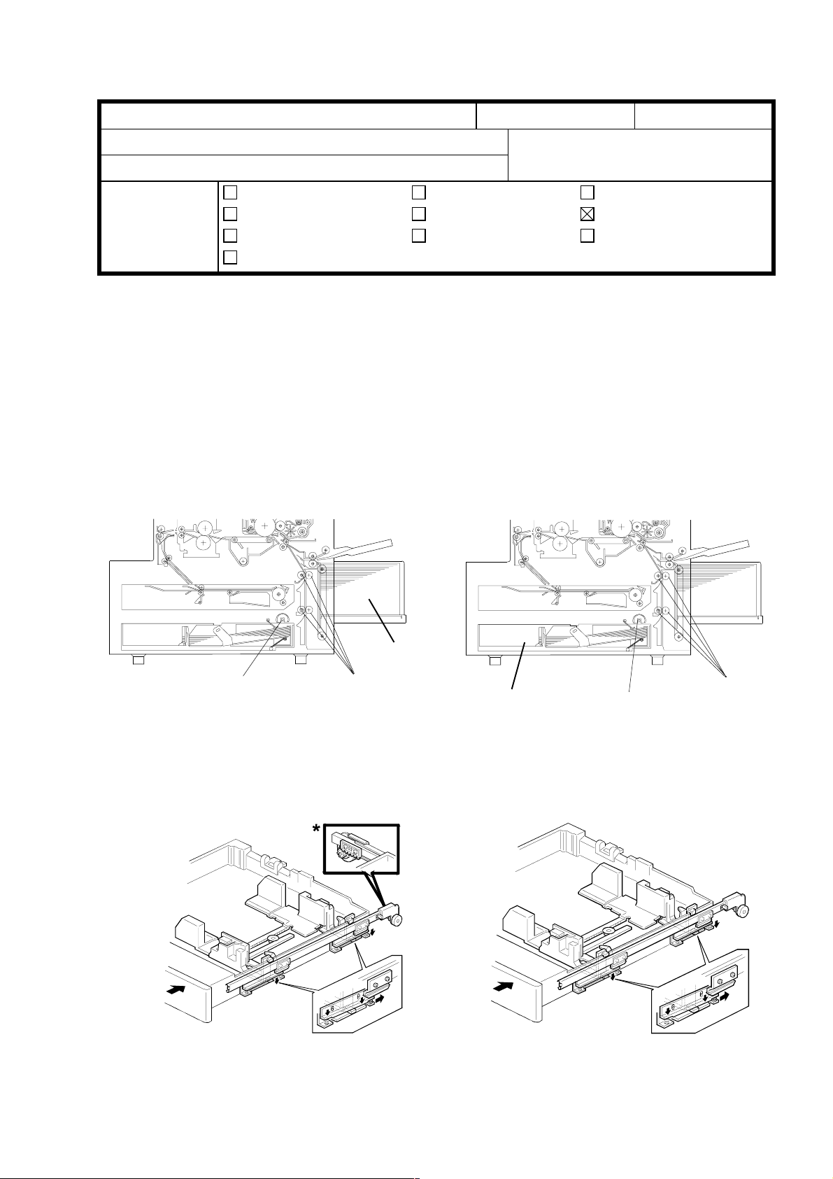
1. Please correct your Service Manual as follows:
Page 13/14
Page 20
<OLD>
Service Manual Revision
QAC Field Information Dept.
Troubleshooting
Mechanical
Paper path
Other ( )
L1, L2 and L3, delete the sentences marked with *.
Callout [A] was positioned incorrectly in the illustration.
Part information
Electrical
Transmit/receive
<NEW>
Prepared by:
Action required
Service manual revision
Retrofit information
K. Miura
Page 24
This copier does not have a damper at the end of the paper tray guide rail. Delete
the last sentence and also the illustration as shown below.
<OLD>
[B]
[C]
* [A]
*[A]
<NEW>
[B]
[C]
T
Model:
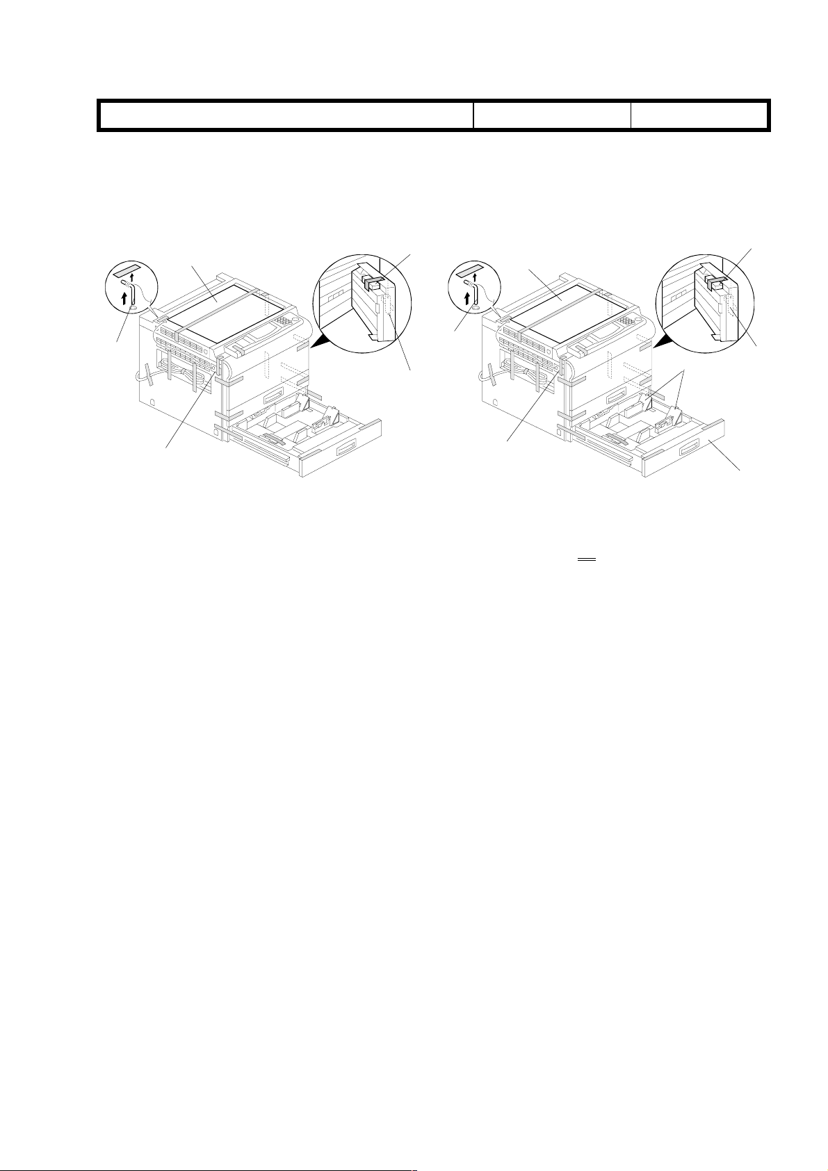
Page 27
Phoenix II Series (Swallow II)
Callouts [G] and [H] were not included in the illustration.
echnical
B
ulletin
Date:
15-Dec-97
No:
PAGE: 2/4
2
<OLD>
[A]
Page 32
[E]
[B]
Change the paragraph
IMPORTANT
<NEW>
[C]
[E]
[A]
[D]
[B]
from step 20 to step 21.
[C]
[D]
[H]*
[G]*
T
(
)
y
p
y
p
(
p
y-p
(
)
Model:
Page 73
Phoenix II Series (Swallow II)
echnical
B
ulletin
Date:
15-Dec-97
No:
PAGE: 3/4
2
Replace
Page 73
following page.)
4. Cleaning Unit
(every 120 k)
5. Development Unit
every 120 k
with the following information. (Refer to the explanations on the
Clean the inside of the cleaning unit and the
1.
seals.
Replace the cleaning blade.
2.
Remove the old developer.
1.
*1
Clean the development unit and seals.
2.
Clean around the openings of the toner supply
3.
unit with a blower brush.
Pour in a pack of new developer.
4.
Replace the development filter.
5.
6. Paper Feed
(every 120 k for each
paper feed station)
*3
Replace pick-up,
feed and se
rollers for b
feed, and the LCT
every 240 k
*4
Replace the
se
aration torque
limiter for the b
ass feedstation
every 240 k).
aration
ass
.
-
1.
Clean the paper guide plate.
*2
Clean the paper feed, pick-up, separation, and
2.
rela
rollers for by-pass feed, and the LCT.
Replace the paper feed rollers for each paper
3.
feed station.
Replace the bottom plate pad for each paper
4.
feed station, by-pass feed, and the LCT.
Clean the registration rollers.
5.
T
Model:
2. The paper registration mechanism has been changed from the Swallow Mark I, and this
information was not listed in the insert version service manual. Please add the following
to your Swallow II manual.
Phoenix II Series (Swallow II)
*1
The manual has been corrected. The PM interval for the development unit is 120k.
*2
The explanations have been revised to match the PM table.
*3
The paper feed station only has semi-circular feed rollers, which are replaced every
120k.
*4
“A214 only” has been deleted, since all models have a by-pass feed separation
torque limiter.
echnical
B
ulletin
Date:
15-Dec-97
No:
PAGE: 4/4
2
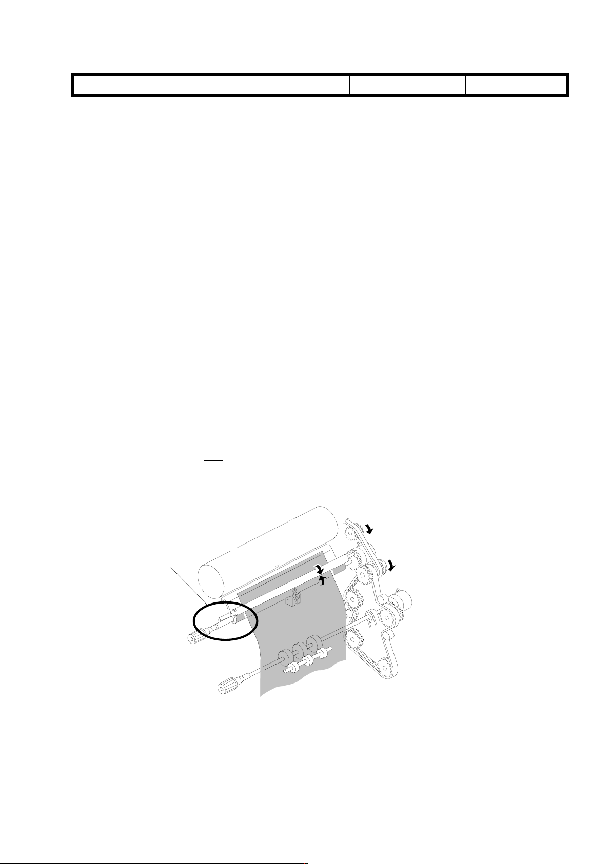
9.5 PAPER REGISTRATION
This copier does
registration rollers. (The rollers marked * on the illustration below.) The upper roller
is driven by the lower roller due to pressure from springs.
not
have gears on the front side that engage the upper and lower
*
T
Model: Swallow 2 Date:
echnical
B
ulletin
98 Mar 13
No:
PAGE: 1/2
3
Subject:
From:
Classification:
Knocking Noise from Pick-off Pawl Cam Gear
QAC Field Information Dept.
Troubleshooting
Mechanical
Paper path
Other ( )
Part information
Electrical
Transmit/receive
Prepared by: S. Hizen
Action required
Service manual revision
Retrofit information
SYMPTOM
♦ A knocking sound from the drum unit.
♦ No side-to-side movement of the pick-off pawls
CAUSE
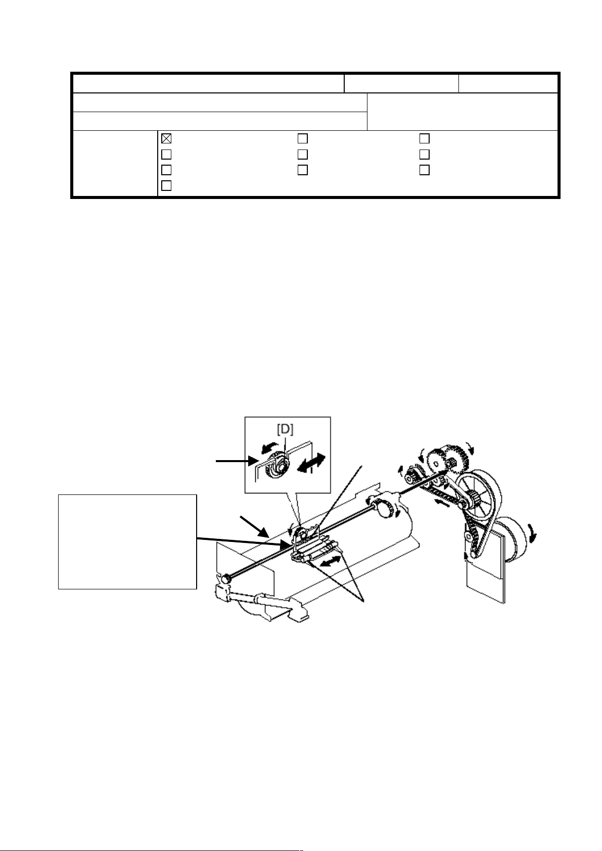
The cam gear (P/N: AB01-7376) on the drum unit is not meshing properly with the worm
gear shaft (P/N: AA14-0560) of the pick-off pawl. The distance between the cam gear and
the worm gear shaft is wider than the specifications.
SOLUTION
Change the 40Z cam gear to a 42Z cam gear (P/N: A212-3567: Black Cam Gear).
Cam Gear
Make sure that the
cam gear is meshing
properly with the worm
gear. If not, please
change the cam gear
from 40Z to 42Z.
Drum Frame
Worm Gear
Pick-off Pawls
COUNTERMEASURE
The cam gear has been changed from 40Z (P/N: AB01-7376) to 42Z (P/N: A212-3567) in
the mass-production units. The color of the cam gear has also been changed from white
to black.

T
echnical
B
ulletin
PAGE: 2/2
Targeted Machines
The cam gear modification has been implemented from the following units onward.
Start serial numbers for 42Z cam gear
RIF Units
Model Serial Numbers
A212-52 AP08630135~
A212-56 3M96380001~
A212-57 A7668630001~
A214-52 AP28630001~
A214-56 3N06380001~
A214-57 A7678630001~
Sindo Ricoh Units
Model Serial Numbers
A212 -10 AP18020001~
-15 1B18020001~
-17 A7668020293~
-22 AP08020021~
A214 -10 AP38020001~
-15 1B28020001~
-17 A7678020285~
-22 AP28030001~
-27 A7678030031~
-29 A7678030001~
 Loading...