

Page 1

DUPLEX AND LCT UNIT
Page 2
Duplex and
LCT Unit
1 February 1994 OVERALL MACHINE INFORMATION
1. OVERALL MACHINE INFORMATION
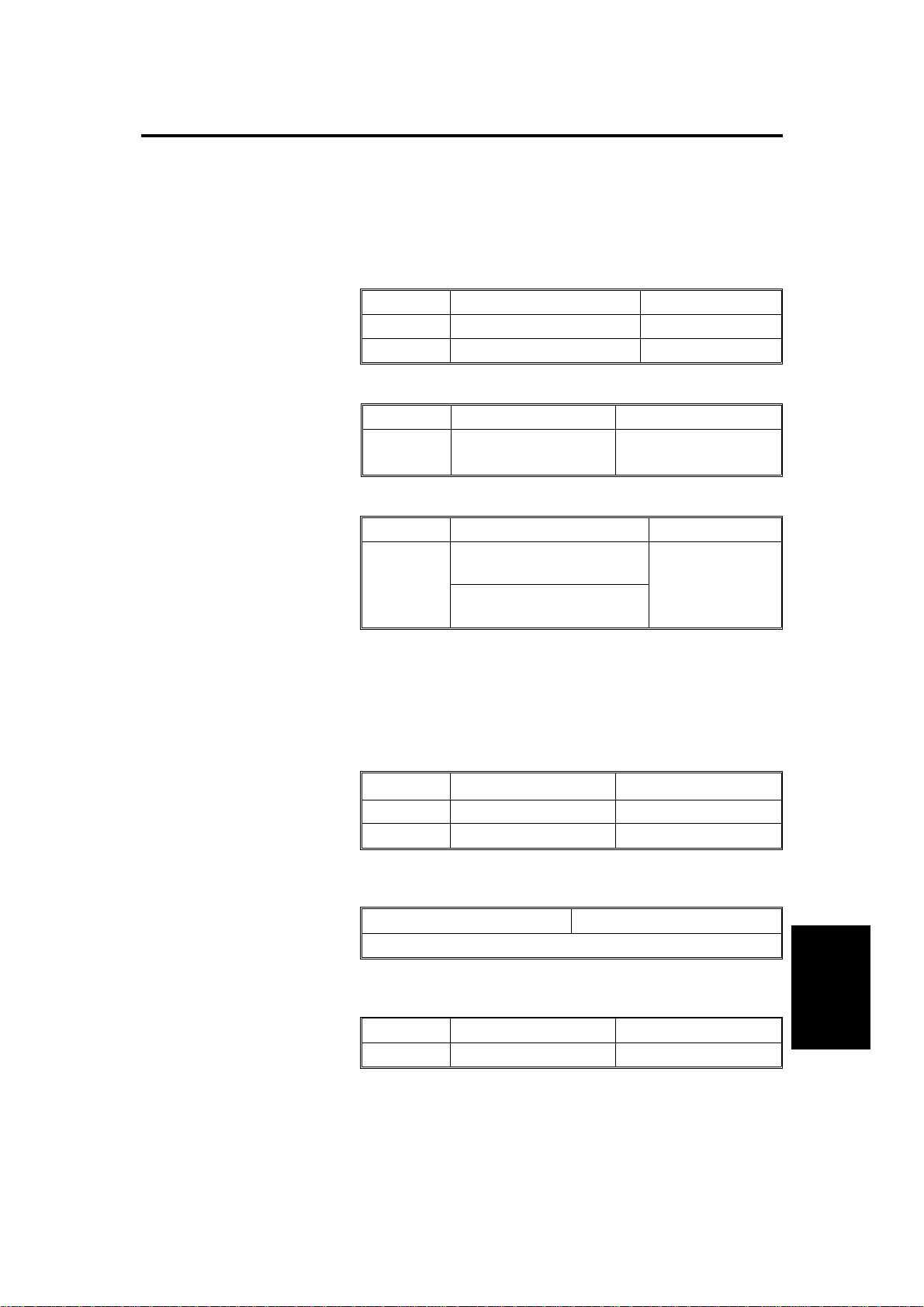
1.1 SPECIFICATION
Configuration: LCT Table or Duplex and LCT Table
Copy Paper Size:
Duplex LCT
Maximum 11" x 17"/A3 10" x 14"/B4
Minimum 8
Copy Paper Weight:
Paper
Weight
Copy Paper Capacity:
Paper
Capacity
1/2" x 51/2"/A5 sideways 81/2" x 11"/A4
Duplex LCT
17
∼ 28 lb/
64
∼ 105 g/m
Duplex LCT
50 copies
(8
1/2" x 11"/A4 or smaller)
30 copies
(11" x 17"/A3, 10" x 14"/B4)
2
17 ∼ 28 lb/
64
∼ 105 g/m
approximately
1,000 sheets
2
Paper Feeding System: FRR system
Power Source: DC 24 V and 5 V from the copier
Power Consumption:
Duplex and LCT LCT
Maximum 79 W 17 W
Average 43 W 16 W
Dimensions (W x D x H):
Duplex and LCT LCT
27.6" x 25.8" x 15.7"/700 mm x 655 mm x 400 mm
Weight:
Duplex and LCT LCT
Weight Less than 127 lb/58 kg Less than 110 lb/50 kg
1
Page 3
OVERALL MACHINE INFORMATION 1 February 1994
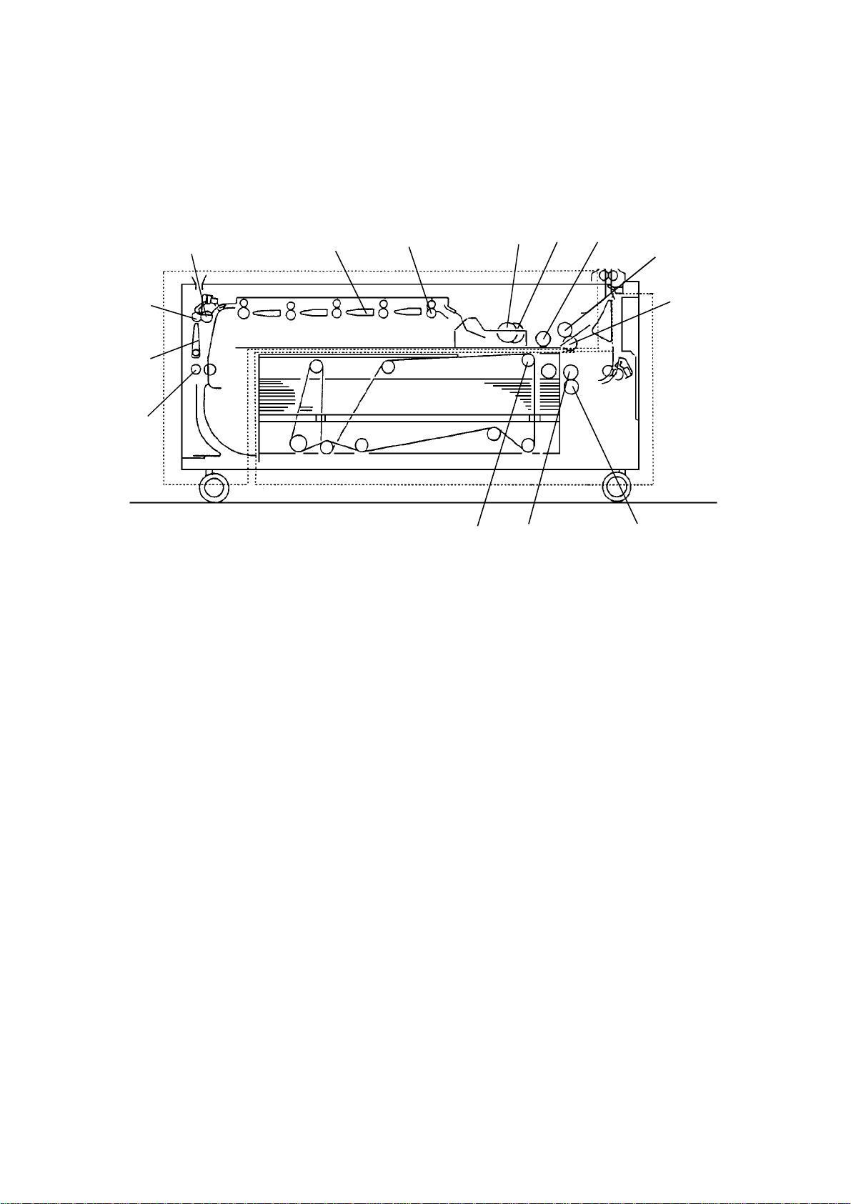
1.2 MECHANICAL COMPONENT LAYOUT
6 7
2
3
4
5
8
1
14
13
1. Relay Pinch Roller
2. Inverter Roller
12
11
8. Duplex Paper Feed Roller
9. Duplex Separation Roller
9
10
3. Fork Gates
4. Duplex Transport Rollers
5. Duplex Positioning Roller
6. Actuator Roller
7. Duplex Pick-up Roller
10. LCT Separation Roller
11. LCT Paper Feed Roller
12. LCT Pick-up Roller
13. Return Pinch Roller
14. Inver Entrance Gate
2
Page 4

Duplex and
LCT Unit
1 February 1994 OVERALL MACHINE INFORMATION
1.3 ELECTRICAL COMPONENT DESCRIPTION
SYMBOL NAME FUNCTION INDEX No.
Motors
M1 Duplex/LCT Motor Drives all mechanical components in the
duplex and LCT units.
M2 Tray Motor Raises and lowers the LCT bottom plate. 4
M3 Jogger Motor Drives the jogger plates to keep paper
evenly stacked on the duplex tray.
Magnetic Clutches
MC1 Duplex Drive Clutch Transmits the drive to the duplex unit. 23
MC2 Duplex Paper Feed
Clutch
MC3 LCT Paper Feed
Clutch
MC4 Relay Clutch Turns the relay rollers. 17
Feeds the paper from the duplex tray.
Feeds the paper from the LCT.
12
21
16
14
Solenoids
SOL1 Relay Pinch Roller
Solenoid
SOL2 Duplex Entrance
Gate Solenoid
SOL3 Lock Solenoid
Duplex
SOL4 Fork Gate Solenoid1Opens and closes the appropriate fork
SOL5 Fork Gate Solenoid2Opens and closes the appropriate fork
SOL6 Duplex Position
Roller Solenoid
SOL7 Duplex Pick-up
Solenoid
SOL8 Duplex Stopper
Solenoid
SOL9 LCT Pick-up
Solenoid
Switches
SW1 Right Lower Door
Switch
SW2 Lower Tray Button
Switch
SW3 Upper Limit Switch Cuts the signal line of the tray up. 2
Separates the relay pinch roller from the
inverter roller.
Energizes to direct the paper to the
duplex unit.
Prevents the duplex unit from being
pulled out in operation.
gates according to the paper size.
gates according to the paper size.
Lowers the positioning roller.
Controls the up-down movement of the
duplex pick-up roller.
Stops the paper in the jogger unit.
Controls the up-down movement of the
LCT pick-up roller.
Cuts the dc power when the right lower
door is opened.
Lower the LCT bottom plate.
29
30
13
27
26
20
19
18
28
6
3
3
Page 5

OVERALL MACHINE INFORMATION 1 February 1994
SYMBOL NAME FUNCTION INDEX No.
Sensors
S1 Inverter Entrance
Sensor
Detects misfeed.
33
S2 Inverter Exit Sensor Detects misfeed. 32
S3 Left Lower Door
Safety Sensor
S4 Duplex Unit Sensor Informs the CPU when the duplex unit is
S5 Jogger Home
Position Sensor
S6 Tray Lower Limit
Sensor
S7 Tray Upper Limit
Sensor
Informs the CPU when the left lower door
is closed.
set.
Informs the CPU when the jogger plates
are at home position.
Informs the CPU when the LCT bottom
plate reaches the lower limit position.
Informs the CPU when the LCT bottom
plate reaches the upper limit position.
31
24
22
11
10
S8 Upper Relay Sensor Detects misfeed. 9
S9 Lower Relay Sensor Detects misfeed. 8
S10 Duplex Entrance
Sensor
S11 LCT Paper End
Sensor
S12 Duplex Paper
Sensor
Detects misfeed.
Informs the CPU that there is no paper in
the LCT.
Detects whether or not paper is in the
duplex tray.
15
7
5
S13 Paper Size Sensor Detects the paper size. 1
PCBs
PCB1 Tray DC Drive
Board
Controls all electrical components in the
duplex and LCT unit.
25
4
Page 6
Duplex and
LCT Unit
1 February 1994 DETAILED SECTION DESCRIPTIONS
2. DETAILED SECTION DESCRIPTIONS
2.1 DUPLEX
2.1.1 Paper Inversion
[D]
[C]
[B]
[C]
[F]
[E]
[B]
[A]
[F]
[E]
In the duplex mode, paper passes through the copier inverter unit and then
goes into the duplex inverter section.
When the paper reaches the fusing exit sensor, the relay pinch roller solenoid
[A] is de-energized. The relay pinch roller [B] is pressed against the inverter
roller [C]. The paper is sent to the lower section.
When the paper passes the copier inverter entrance sensor, the duplex
entrance gate solenoid [D] is energized.
The return pinch roller [E] feeds the paper back and the duplex entrance gate
[F] directs the paper to the duplex unit.
5
Page 7
DETAILED SECTION DESCRIPTIONS 1 February 1994
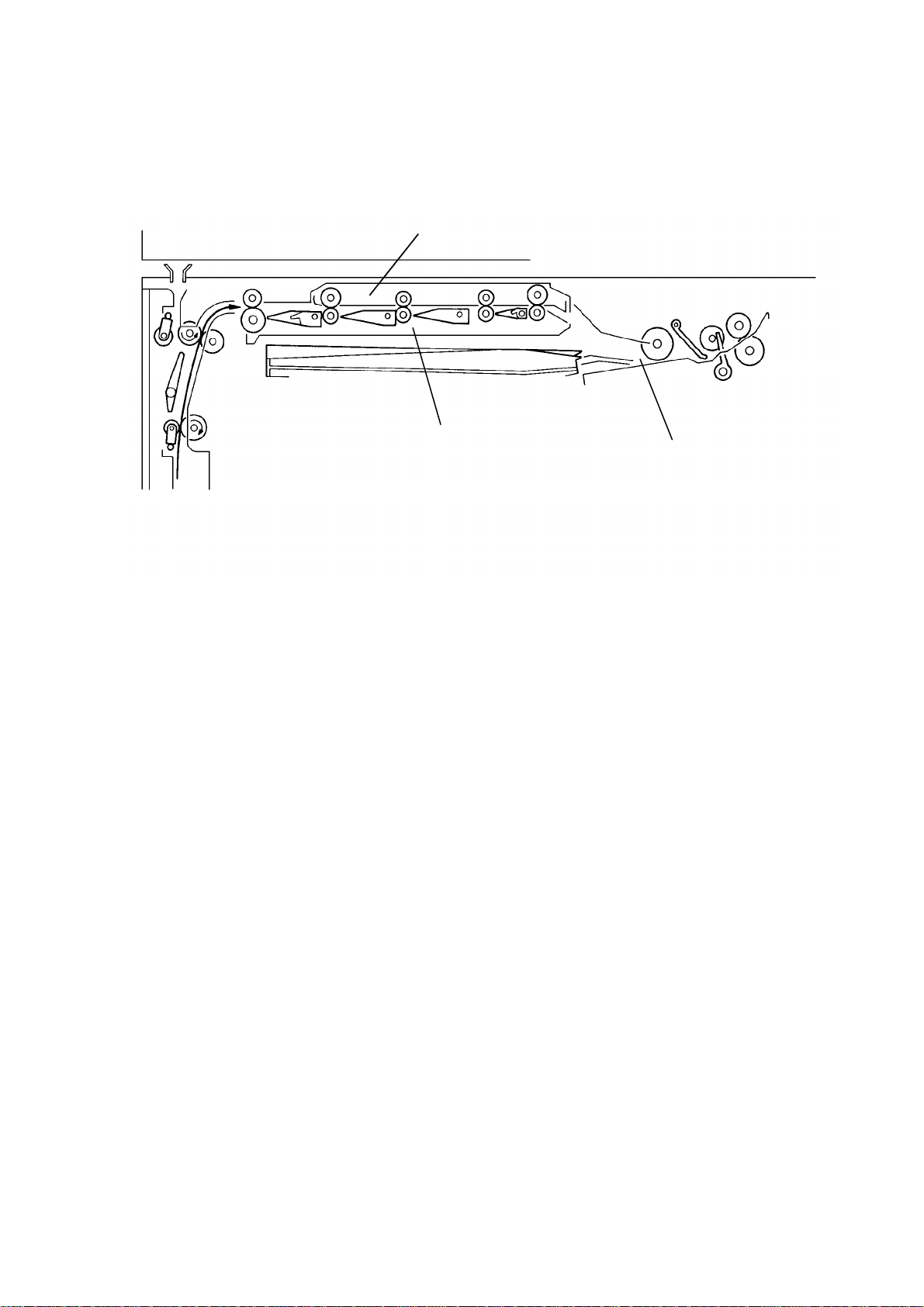
2.1.2 Duplex Transport
[A]
[B]
[C]
After the copy is reversed in the inverter unit, it comes to the duplex transport
section. The duplex transport unit [A] carries the copy from the inverter unit to
the appropriate gate in the fork gate unit [B]. The CPU opens the gate
corresponding to the copy paper size. The copy paper passes through the
gate and is transported to the jogger unit [C].
6
Page 8
Duplex and
LCT Unit
1 February 1994 DETAILED SECTION DESCRIPTIONS
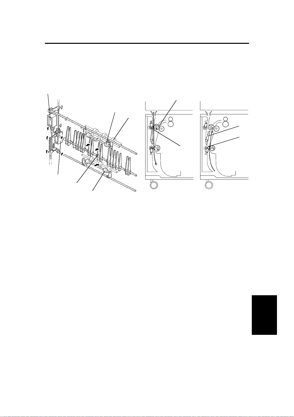
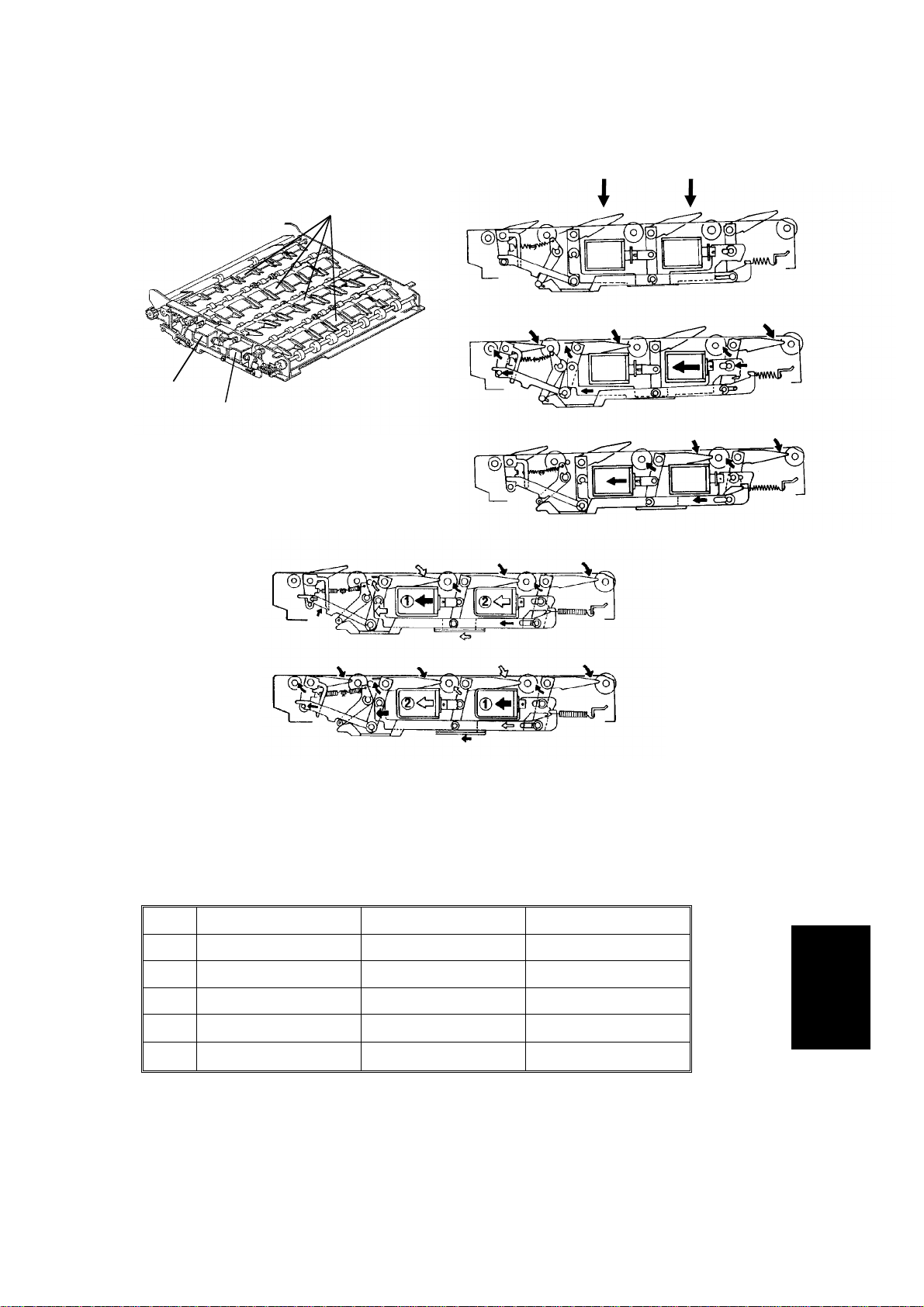
2.1.3 Fork Gate Mechanism
SOL 2
SOL 1
[A]
[D]
[E]
[C]
[B]
[F]
[G]
[H]
NOTE: Numbers circled within solenoid indicate sequence of solenoid
operation.
The fork gate unit has four gates [A] through which copy paper passes to the
duplex tray. Two solenoids [B, C], working together, create any of five
separate states for the fork gates. (See the figure.)
Sol. 1 [B] Sol. 2 [C] Paper Size
[D] OFF OFF 11" x 17"/A3
[E] ON OFF 8
[F] OFF ON 8
[G]
OFF
⇒ ON
ON 11" x 8
1/2" x 14"/B4
1/2" x 11"/A4 (L)
1/2"/A4
[H]
ON
OFF
⇒ ON
8
1/2" x 51/2"/A5
Black arrows indicate initial movement.
7
Page 9
DETAILED SECTION DESCRIPTIONS 1 February 1994
2.1.4 Drive Mechanism
[J]
[H]
[A]
[C]
[G]
[B]
[D]
[I]
[E]
[F]
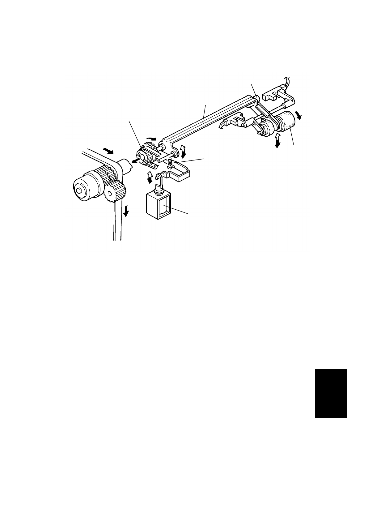
When the duplex unit is set, the duplex drive gear [A] engages with the
duplex gear [B]. The rotation of the duplex/LCT motor is transmitted to the
duplex unit through the duplex drive clutch [C].
The duplex paper feed clutch gear then turns through the idle gear. The
duplex paper feed clutch [D] controls the transmission of the rotation to the
duplex paper feed [E], reverse [F], and pick-up rollers[G].
This drive is also transmitted to the duplex entrance roller gear [H] through
gears and timing belts. All duplex transport rollers [I] are turning.
Drive is then transmitted back to the LCT via the duplex inverter drive gear
[J], and turns the inverter rollers.
8
Page 10
Duplex and
LCT Unit
1 February 1994 DETAILED SECTION DESCRIPTIONS
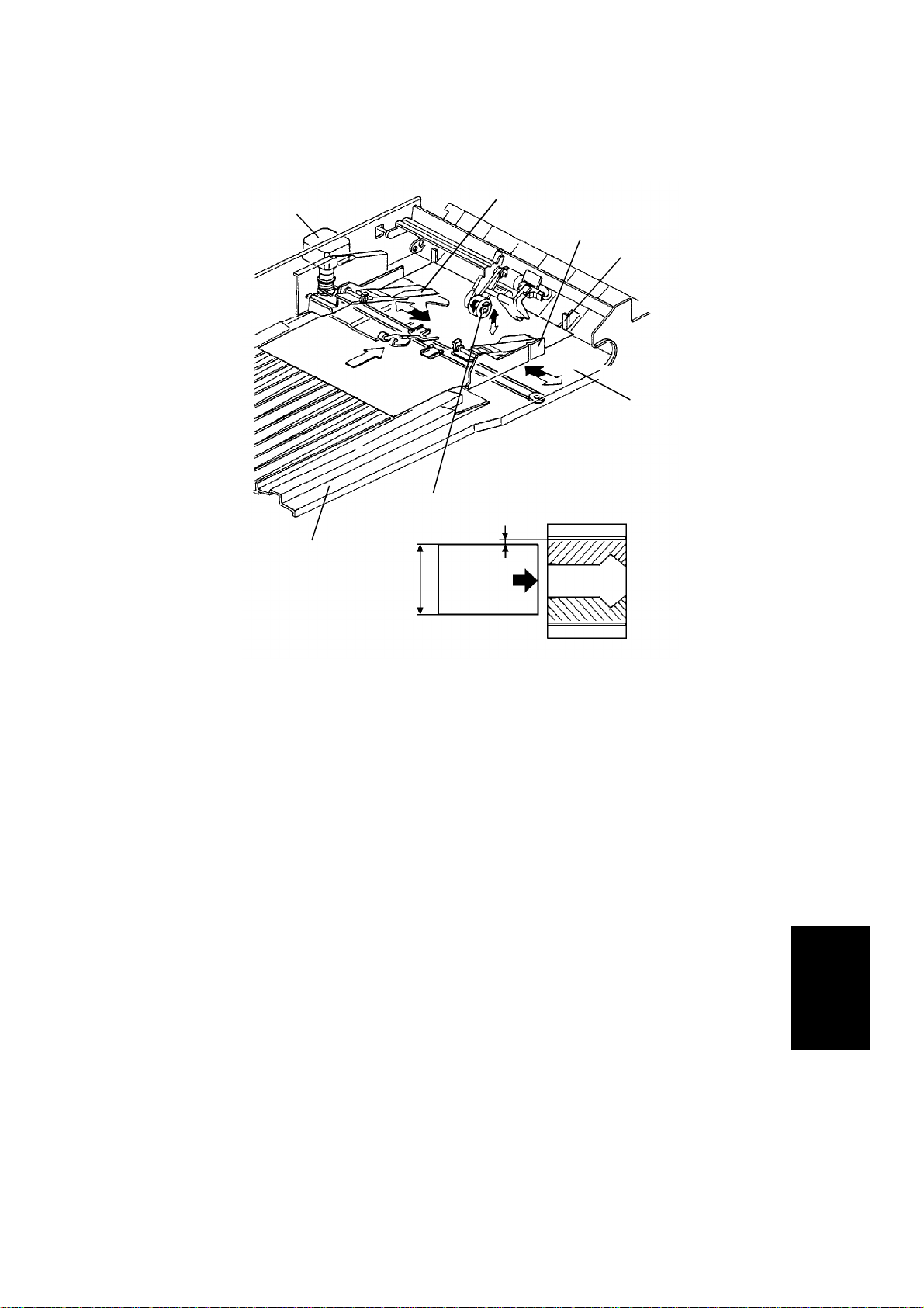
2.1.5 Duplex Stacking
[E]
[C]
[D]
[G]
[B]
[F]
15 mm
[A]
Paper is stacked in the duplex tray, which consists of the duplex delivery tray
[A] and the jogger unit [B].
The duplex delivery tray transports paper from the fork gate unit to the jogger
unit. The duplex delivery tray is ribbed to achieve precise stacking of paper in
the duplex tray.
The jogger unit consists of a drive motor [C], jogger fences [D], duplex
settlers [E], a positioning roller [F], and duplex stoppers [G]. All these
components work together to achieve proper stacking of paper in the duplex
tray.
When the Start key is pressed, the CPU reads the cassette paper size coding
and the jogger fences are positioned 15 mm from either side of the copy
paper. As paper enters the duplex tray, it is positioned under the duplex
settlers. The positioning roller (made of sponge) rotates and pushes the
paper up against the duplex stoppers to correct paper skew. The positioning
roller is then lifted, and the jogger fences move inwards to square the stack
every time a sheet enters the duplex tray.
9
Page 11
DETAILED SECTION DESCRIPTIONS 1 February 1994
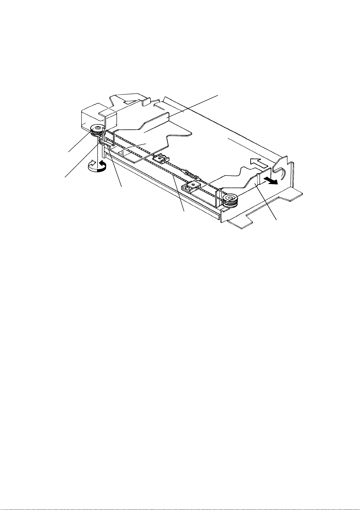
2.1.6 Jogger Drive Mechanism
[B]
[D]
[E]
[F]
[C]
[A]
Both the front [A] and rear [B] fences of the jogger unit are attached to the
same wire [C]. The jogger drive pulley [D] is mounted on the jogger motor
shaft. When the jogger drive pulley turns, both fences move the same
distance in opposite directions. The jogger home position sensor [E] informs
the CPU when the jogger is at the home position.
In duplex mode, when the Start key is pressed, the jogger fences are driven
outward by the stepper motor, and the sensor actuator plate [F] slides
through the slot of the jogger home position sensor to the reference home
position. After the home position is referenced, the jogger fences move
inward and the stop position is determined by the paper size (cassette code).
10
Page 12
Duplex and
LCT Unit
1 February 1994 DETAILED SECTION DESCRIPTIONS
2.1.7 Duplex Positioning Roller
[D]
[C]
[B]
[A]
[E]
[F]
-- Drive Mechanism -The duplex positioning roller [A] is driven by the main drive belt. Power is
transferred from the main drive belt to the positioning roller through the
positioning roller pully [B], the positioning drive shaft [C], the positioning roller
pulley [D], and the rubber belt.
-- Up and Down Mechanism -The positioning roller release spring [E] lifts the positioning roller 7 millimeters
(0.29") above the jogger bottom plate and holds it in this position so that it
does not interfere with the lateral stacking process. When a sheet is fed into
the duplex tray, the positioning roller solenoid [F] energizes, pulling the
positioning roller down to fully advance the copy paper up to the duplex
stopper.
11
Page 13
DETAILED SECTION DESCRIPTIONS 1 February 1994
2.1.8 Duplex Tray Sensors
[F]
[A]
[E]
[D]
[C]
[B]
Duplex Entrance Sensor
When paper enters the duplex tray, the positioning roller bracket [A] is in the
low position and the actuator roller [B] is resting on the jogger bottom plate.
When the paper passes under the actuator roller, the friction of the paper
turns the actuator roller. This rotation moves the entrance actuator [C] up and
down, actuating the entrance sensor.
There are several slots in the entrance actuator [C] that activate the sensor
[D] successively when the actuator roller rotates. If there are more than two
changes (ON - OFF - ON or OFF - ON - OFF) during the checking period, the
CPU determines that paper has entered the duplex tray.
Duplex Paper Sensor
When there is copy paper in the duplex tray, the paper actuator [E] is moved
up and away from the duplex paper sensor [F], which activates the
photointerrupter (5V
→ 0V). This informs the CPU that paper is in the duplex
tray. When the last sheet of paper has entered the duplex tray, the CPU
checks the duplex paper sensor signal and lights the second original
instructions in the guidance display.
12
Page 14
Duplex and
LCT Unit
1 February 1994 DETAILED SECTION DESCRIPTIONS
2.1.9 Duplex Stopper and Pick-up Roller Mechanism
[D]
[C]
[A]
[B]
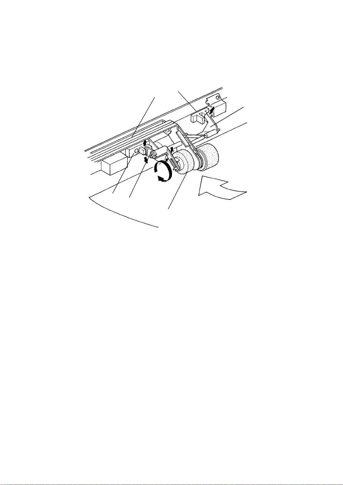
The pick-up roller bracket is lifted up by the rear most duplex stopper [A].
Both the duplex stopper and the pick-up roller [B] are moved by solenoids.
When paper is being fed, the duplex stopper solenoid [C] is energized and
the stoppers are lowered. The pick-up roller bracket rotates downward and
the pick-up roller drops onto the copy paper. The duplex pick-up solenoid [D]
is energized 160 milliseconds after the duplex feed clutch turns on. Paper
feed then begins. The pick-up roller stays in contact with the paper during
paper feed.
13
Page 15
DETAILED SECTION DESCRIPTIONS 1 February 1994
2.2 LCT (Large Capacity Tray)
2.2.1 LCT Drive Mechanism
[E]
[F]
[H]
[D]
[A]
[G]
[B]
[C]
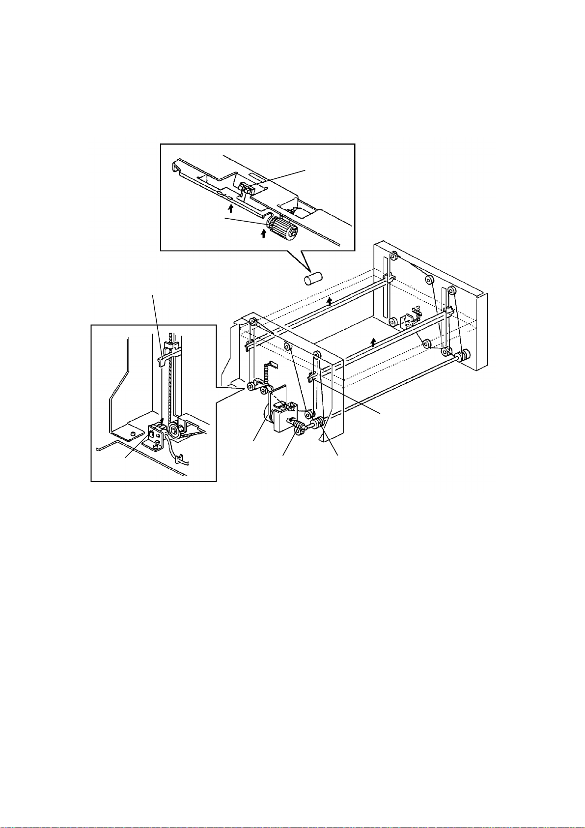
Drive from a reversible motor [A] is transmitted through a worm gear [B] to
the drive pulley [C] shaft. The tray wires have metal hooks on them. These
hooks are set to the stays [D] of the bottom plate, so, when the drive pulley
turns (clockwise, rear view), the hooks on the wires move the tray upward.
The tray goes up until the upper limit sensor [E] is actuated by the top sheet
pushing up the pick-up roller [F].
To lower the tray, the pulley turns counterclockwise until the lower limit
sensor [G] is actuated by the actuator of the bottom plate [H].
14
Page 16

Duplex and
LCT Unit
1 February 1994 DETAILED SECTION DESCRIPTIONS
2.2.2 Tray Lock Mechanism
[A]
[D]
[C]
[B]
When the tray is set, it is positioned by the lock arm [A]. The roller of the lock
arm presses against the lock plate [B]. And the lock lever [C] engages the
tray stopper [D] to prevent the tray from being opened or pulled out while the
tray is in the up position.
When the tray moves to the down position, the tray bottom plate pushes the
lock lever. The tray stopper is disengaged and it is allowing the tray to be
pulled out.
15
Page 17

DETAILED SECTION DESCRIPTIONS 1 February 1994
[A]
[B]
[E]
[C]
[D]
When the tray is pulled out, the pick-up release lever [A] is turned and the
pick-up roller [B] is then lifted up.
At the front side of the tray, there is the paper end feeler lift-up mechanism
[C]. When the tray is pulled out, the paper end release lever [D] turns and the
paper end feeler [E] is lifted up.
These prevent the pick-up roller and the paper end feeler from hitting the tray
rear frame, when the tray is pulled out.
16
Page 18

Duplex and
LCT Unit
1 February 1994 DETAILED SECTION DESCRIPTIONS
2.2.3 Paper End Detection
[B]
[A]
When paper is in the tray, the paper lifts the paper end actuator [A] up. When
the paper runs out, the paper end actuator falls through a hole in the bottom
plate and other end of the actuator activates the paper end sensor [B]. The
Add Paper indicator then lights.
17
Page 19

DETAILED SECTION DESCRIPTIONS 1 February 1994
2.2.4 Paper Size Detection
[C]
[D]
[C]
[D]
[A]
[B]
The rear side fence [A] and the front side fence [B] can be moved to change
the paper size.
The array of five photointerrupters [C] installed at the front side of the tray
detects the paper size.
Each paper size has its own unique combination of notches in the paper size
plate [D].
The CPU reads which photointerrupters have been de-activated by the paper
size plate to determine which paper size has been set.
Whenever both front and rear side fences are moved for changing paper
size, this paper size plate should also be moved to the proper position.
18
Page 20

Duplex and
LCT Unit
1 February 1994 DETAILED SECTION DESCRIPTIONS
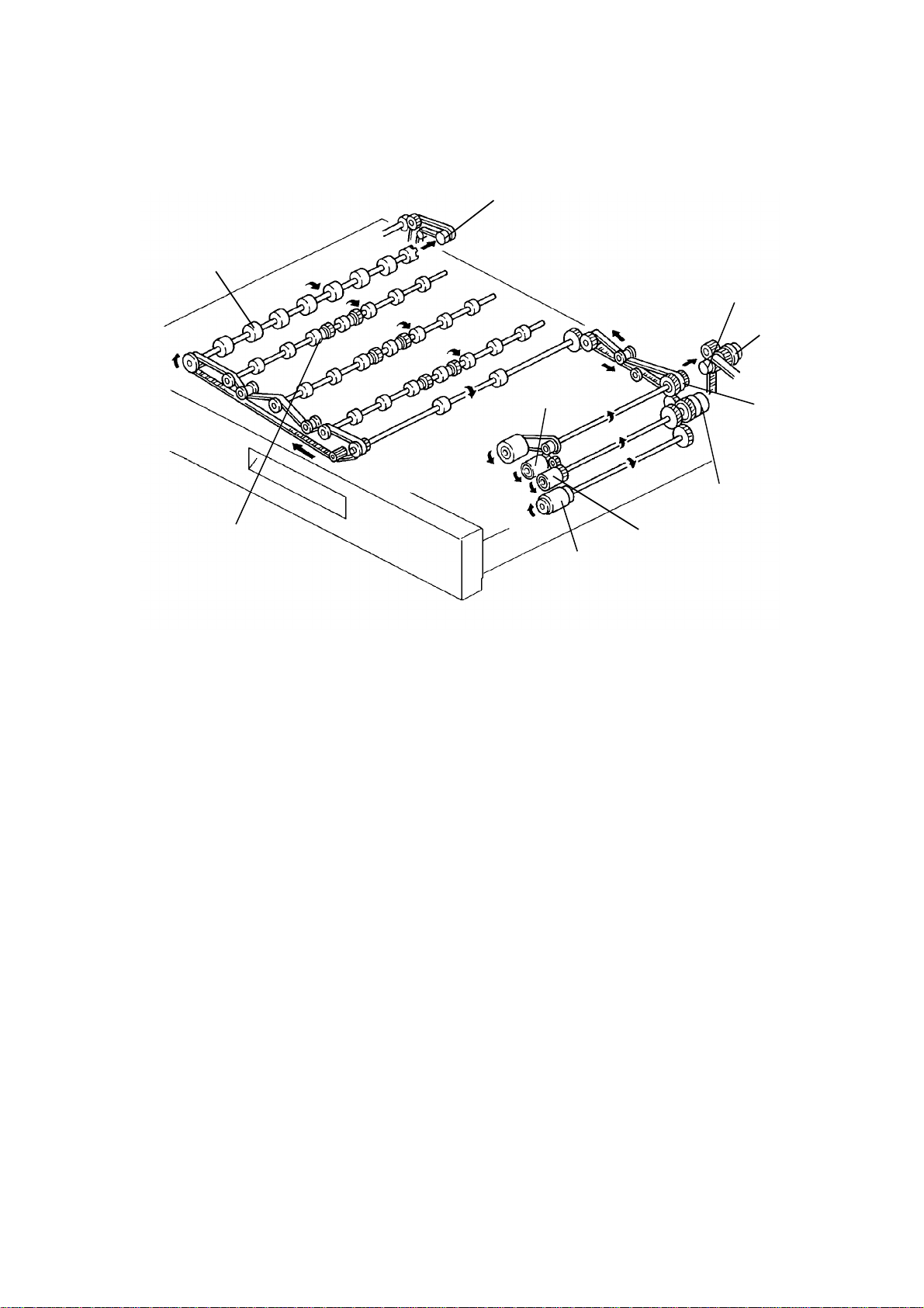
2.2.5 Paper Feed Drive Mechanism
[F]
[A]
[E]
[B]
[C]
[D]
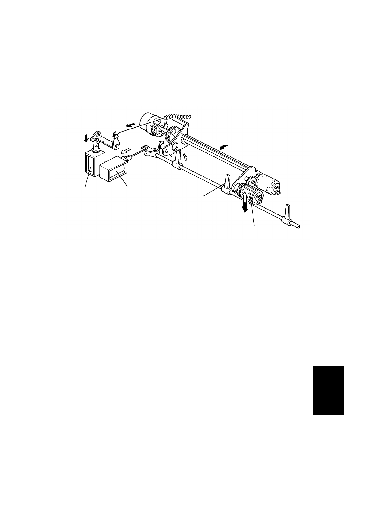
The rotation of the duplex/LCT motor [A] is transmitted to the paper feed
drive and the duplex unit drive via gears and a timing belt.
The tray paper feed clutch [B] controls the drive transmission to the paper
feed roller [C], reverse roller [D] and pick-up roller [E].
The relay clutch [F] controls the drive transmission to the relay rollers.
19
Page 21

INSTALLATION 1 February 1994
3. INSTALLATION
3.1 ACCESSORY CHECK
1. Installation Procedure (115 V version only)...........1 pc
2. NECR (115 V version only) ................................... 1 pc
3. Envelope for NECR (115 V version only)..............1 pc
4. Philips Tapping Screw M4 x 8............................... 1 pc
20
Page 22

Duplex and
LCT Unit
1 February 1994 INSTALLATION
3.2 INSTALLATION PROCEDURE
[A]
[A]
[A]
[C]
[B]
[H]
[F]
[E]
[E]
[D]
1. Remove the strips of filament tape [A] from the LCT and Duplex Unit.
2. Pull out the duplex tray and remove the filament tape [B] and cushion [C].
3. Remove the rear cover [D] (3 screws) and rear side covers [E] (2 screws
each).
[G]
4. Remove the shipping retainers [F] (1 screw each).
5. Place the copier on the unit by using the lift handles [G]. Make sure the
pegs [H] fit into the copier’s peg holes.
21
Page 23

INSTALLATION 1 February 1994
[C]
[B]
[A]
[D]
[E]
[F]
6. Remove the copier’s rear lower cover (4 screws) and the base cover
bracket [A] (2 screws).
7. Connect the 3 connectors to the copier’s main PCB [B], and secure the
harness in the clamps [C] as shown.
8. Secure the ground wire [D] (1 M4 x 8 philips tapping screw).
9. Push the lift handles [E] back in the copier and install the rear side covers
[F] over the handles.
10. Reinstall the rear covers.
22
Page 24

Duplex and
LCT Unit
1 February 1994 INSTALLATION
[B]
[E]
[A]
[C]
[D]
NOTE: Step 11 to 14 are for paper size setting change.
11. Pull out the LCT and open the top cover [A].
12. Position the paper size plate [B] to match the desired paper size
(1 screw).
13. Position the rear side fence [C] and the front side fence [D] to match the
desired paper size (1 screw each).
14. Position the end fence [E] to match the desired paper size.
15. Load paper and close the top cover.
16. Reinstall the LCT and check machine operation.
23
Page 25

REPLACEMENT AND ADJUSTMENT 1 February 1994
4. REPLACEMENT AND ADJUSTMENT
4.1 LCT
4.1.1 LCT Removal
[E]
[D]
[A]
[B]
[C]
NOTE: Push the red button to lower the tray before opening the LCT.
1. Pull out the duplex tray [A] and the LCT [B].
2. Remove the duplex and LCT unit front right cover [C] (2 screws).
3. Remove the unit’s left front cover (2 screws) and remove the front left
cover [D] (3 screws).
4. Set the duplex tray [A] back in.
5. Pull the LCT [E] all the way out.
6. Remove the LCT [E] (6 screws).
24
Page 26

Duplex and
LCT Unit
1 February 1994 REPLACEMENT AND ADJUSTMENT
4.1.2 LCT Motor Replacement
[C]
[A]
[B]
[D]
1. Remove the LCT. (See LCT Removal section.)
2. Disconnect the LCT motor connector [A].
3. Remove the LCT motor unit [B] (4 screws).
4. Remove the LCT motor [C] (4 screws).
5. Remove the motor gear [D] (2 Allen screws) and replace the LCT motor.
25
Page 27

REPLACEMENT AND ADJUSTMENT 1 February 1994
4.1.3 Paper Size Sensor Replacement
[C]
[A]
[B]
[E]
[D]
[G]
1. Pull out the LCT [A].
[F]
2. Remove the front side fence lock [B] (1 screw).
3. Remove the LCT front cover [C] (3 screws, 2 connectors).
4. Remove the size actuator board lock [D] (1 screw), and remove the size
actuator board [E].
5. Remove the paper size sensor unit [F] (1 screw).
6. Replace the paper size sensor [G] (1 screw).
26
Page 28

Duplex and
LCT Unit
1 February 1994 REPLACEMENT AND ADJUSTMENT
4.1.4 Tray Lower Limit Sensor Replacement
[B]
[C]
[A]
1. Remove the LCT. (See LCT Removal section.)
2. Disconnect the connector [A] on the tray lower limit sensor [B].
3. Remove the tray lower limit sensor unit [C] (1 screw).
4. Remove the tray lower limit sensor [B] from the bracket.
27
Page 29

REPLACEMENT AND ADJUSTMENT 1 February 1994
4.1.5 Lower Tray Button Switch Replacement
[A]
[B]
[D]
[E]
[C]
1. Pull out the LCT [A].
2. Remove the front side fence lock [B] (1 screw).
3. Remove the LCT front cover [C] (3 screws).
4. Free the harness from the clamp [D] and remove the lower tray button
switch [E] (2 screws).
28
Page 30

Duplex and
LCT Unit
1 February 1994 REPLACEMENT AND ADJUSTMENT
4.1.6 LCT Front Wire Replacement
-- Removal --
[A]
[C]
[D]
[B]
[E]
[G]
[H]
1. Remove the LCT. (See LCT Removal section.)
2. Remove the front side-fence lock [A] (1 screw).
3. Remove the front cover [B] (3 screws, 2 connectors).
4. Remove the harness guide bracket [C] (1 screw).
5. Free the tray lock brackets [D] from the tray stay [E] as shown in the
figure.
[F]
6. Remove the spring [F].
7. Loosen the screw [G] securing the arm bracket [H].
8. Remove the wire.
29
Page 31

REPLACEMENT AND ADJUSTMENT 1 February 1994
-- Installation --
[B]
⑤
[A]
④
②
①
⑥
⑦
⑧
③ ⑨
1. Manually rotate the drive pulley [A] so that the slit is vertical.
2. Install the wire which has a red mark at the edge on the drive pulley and
wrap it 2 times around clockwise.
3. Place a small blade screw driver [B] through the pulley and into the hole
to secure the pulley as shown in the figure.
4. Run the wire over the pulleys in the following order: [C]
• 13/4 turns over the drive pulley ①
• 1/2 turn over pulley ②
• 1/2 turn over pulley ③ (rear)
• 1/4 turn over pulley ④
• 1/4 turn over pulley ⑤
• 1/2 turn over pulley ⑥
• 1/4 turn over pulley ⑦
• 1/4 turn over pulley ⑧
• 1/4 turn over pulley ⑨ (front)
30
Page 32

Duplex and
LCT Unit
1 February 1994 REPLACEMENT AND ADJUSTMENT
[H]
[G]
[F]
[D]
[E]
5. Remove the small blade screw driver [D] securing the drive pulley.
6. Install the end of the wire in the drive pulley and wrap it 3 times around
counter clockwise, as shown in the figure [E].
7. Reinstall the spring [F] and secure the arm bracket screw [G].
8. While lifting the tray manually, hook the tray lock brackets [H] back on.
9. Reinstall the unit and check machine operation.
31
Page 33

REPLACEMENT AND ADJUSTMENT 1 February 1994
4.1.7 LCT Rear Wire Replacement
-- Removal --
1. Remove the LCT motor unit. (See LCT Motor Replacement section.)
2. Remove the lower limit sensor. (See Lower Limit Sensor Replacement
section.)
3. Perform steps 5 to 8 of the LCT Front Wire Replacement section.
-- Installation --
The reinstallation of the rear wire is basically the same as that of the front
wire. Make sure of the following points and install the rear wire according to
the front wire installation procedure.
• When first installing the red marked edge onto the drive pulley, wrap it
around counterclockwise.
• When installing the end of the wire onto the drive pulley, wrap it around
clockwiseway.
32
Page 34

Duplex and
LCT Unit
1 February 1994 REPLACEMENT AND ADJUSTMENT
4.1.8 Paper Feed, Pick Up and Reverse Roller Replacement
[C]
[B]
[A]
1. Remove the LCT. (See LCT Removal section.)
2. Remove the rollers in the following order.
• Reverse roller [A] (1 snap ring)
• Paper feed roller [B] (1 snap ring)
• Pick up roller [C] (1 snap ring)
NOTE: When installing the new rollers, make sure not to touch the
rubber surface with bare hands.
33
Page 35

REPLACEMENT AND ADJUSTMENT 1 February 1994
4.2 DUPLEX TRAY
4.2.1 Duplex Tray Removal
[E]
[D]
[E]
[B]
[C][A]
NOTE: Push the red button to lower the tray before opening the LCT.
1. Pull out the duplex tray [A] and the LCT [B].
2. Remove the duplex and LCT unit front right cover [C] ( 2 screws).
3. Remove the unit’s left front cover (2 screws) and remove the front left
cover [D] (3 screws).
4. Remove both duplex tray lock brackets [E] (3 screws).
5. Remove the duplex tray [A].
34
Page 36

Duplex and
LCT Unit
1 February 1994 REPLACEMENT AND ADJUSTMENT
4.2.2 Jogger Drive Wire Replacement
-- Removal --
[A]
[B]
[C]
[D]
1. Remove the duplex tray. (See Duplex Tray Removal section.)
2. Remove the front wire lock bracket (with cushion) [A] and the rear wire
lock bracket [B] (1 screw each).
3. Turn over the duplex tray and remove the wire spring [C].
4. Remove the jogger drive wire [D].
35
Page 37

REPLACEMENT AND ADJUSTMENT 1 February 1994
-- Installation --
③
①
②
⑤
④
[B]
[A]
5. Set the new wire in the following way:
• Hook the wire which is not marked red to the spring
• Secure the other end of the spring to the bracket
• 1/2 turn over the pulley
• 11/2 turns over the jogger motor pulley
• Remove the spring from the bracket and hook the end of the wire
(marked red) to the spring.
• Reinstall the 2 wire brackets [A] [B] to secure the wire.
36
Page 38

Duplex and
LCT Unit
1 February 1994 REPLACEMENT AND ADJUSTMENT
4.2.3 Paper Feed, Pick Up and Reverse Roller Replacement
[A]
[B]
[C]
1. Pull out the duplex tray.
2. Remove the pick up [A] paper feed [B], and reverse rollers [C] (1 snap
ring each).
NOTE: When installing the new rollers, make sure not to touch the
rubber surface with bare hands.
37
Page 39

REPLACEMENT AND ADJUSTMENT 1 February 1994
4.2.4 Position Roller Belt Replacement
[C]
[A]
[B]
1. Pull out the duplex tray.
2. Remove the snap ring [A] on the position roller [B].
3. While holding the position roller belt [C], remove the position roller [B].
NOTE: When installing the new position roller, make sure not to touch
the roller surface with bare hands.
38
Page 40

Duplex and
LCT Unit
1 February 1994 REPLACEMENT AND ADJUSTMENT
[A]
[C]
[B]
[E]
4.2.5 Duplex Paper Sensor Replacement
1. Pull out the duplex tray.
2. Disconnect the paper end sensor connector [A].
[D]
3. Remove the duplex paper sensor unit [B] (1 screw).
4. Replace the duplex paper sensor [C] (1 screw).
4.2.6 Entrance Sensor and Actuator Roller Replacement
1. Pull out the duplex tray.
2. Disconnect the entrance sensor connector [D].
3. Replace the entrance sensor [E] (1 screw).
39
Page 41

REPLACEMENT AND ADJUSTMENT 1 February 1994
4.2.7 Jogger Home Position Sensor Replacement
[A]
1. Remove the duplex tray. (See Duplex Tray Removal section.)
2. Replace the jogger home position sensor [A] (1 screw, 1 connector).
40
Page 42

Duplex and
LCT Unit
1 February 1994 REPLACEMENT AND ADJUSTMENT
4.3 DUPLEX AND LCT UNIT
4.3.1 Duplex Tray Set Sensor Replacement
[D]
[A]
[B]
[C]
1. Remove the Duplex and LCT Unit rear cover [A] (3 screws).
2. Disconnect the connector [B] on the duplex tray set sensor.
3. Remove the duplex tray set sensor unit [C] (1 screw).
4. Replace the duplex tray set sensor [D] (1 screw).
41
Page 43

REPLACEMENT AND ADJUSTMENT 1 February 1994
4.3.2 DC Drive Board Replacement
[A]
[B]
1. Turn off the main and anti-condensation switches.
2. Remove the duplex and LCT unit rear cover [A] (3 screws).
3. Replace the DC drive board [B] (8 connectors, 4 clamps).
42
Page 44

Duplex and
LCT Unit
1 February 1994 REPLACEMENT AND ADJUSTMENT
4.3.3 Right Lower Doors Switch Replacement
[D]
[E]
[B]
[A]
[C]
1. Pull out the duplex tray [A] and the LCT [B].
2. Remove the front right cover [C] (2 screws).
3. Remove the right lower door switch unit [D] (1 screws, 3 connectors).
4. Replace the right lower door switch [E] (2 screws).
43
Page 45

REPLACEMENT AND ADJUSTMENT 1 February 1994
4.3.4 Duplex and LCT Motor Replacement
[A]
[B]
1. Pull out the duplex tray and the LCT.
2. Turn off the main and anti-condensation switches.
3. Remove the duplex and LCT unit rear cover [A] (3 screws).
4. Remove the duplex and LCT motor [B] (3 screws, 1 connector).
NOTE: When installing, make sure the drive belt is positioned properly.
44
Page 46

Duplex and
LCT Unit
1 February 1994 REPLACEMENT AND ADJUSTMENT
4.3.5 Upper Relay Sensor Replacement
[D]
[A]
[E]
[B]
1. Remove the duplex and LCT unit right upper cover [A] and right rear
cover [B] (2 screws each).
2. Disconnect the connector of the upper relay sensor [C] and free the
harness from the metal clamps.
3. Remove the upper relay sensor unit [D] (1 screw).
4. Replace the upper relay sensor [E].
[C]
45
Page 47

REPLACEMENT AND ADJUSTMENT 1 February 1994
4.3.6 Lower Relay Sensor Replacement
[D]
[E]
[A]
[C]
[B]
1. Open the duplex and LCT unit right door [A].
2. Remove the units right rear cover [G] (2 screws).
3. Disconnect the connector of the lower relay sensor [C] and free the
harnesses from the metal clamps.
4. Remove the lower relay sensor unit [D] (1 screw).
5. Replace the lower relay sensor [E].
46
Page 48

Duplex and
LCT Unit
1 February 1994 REPLACEMENT AND ADJUSTMENT
4.3.7 Left Lower Door Sensor Replacement (A306 only)
[B]
[A]
1. Open the duplex and LCT unit left door [A].
2. Remove the duplex and LCT unit left rear cover [B] (2 screws).
3. Remove the left lower door sensor unit [C] (1 screw).
4. Replace the left lower door sensor [D] (1 connector).
[C]
[D]
47
 Loading...