

Page 1

DOCUMENT FEEDER
Page 2

1 February 1994 OVERALL MACHINE INFORMATION
1. OVERALL MACHINE INFORMATION
1.1 SPECIFICATIONS
Original Size and Weight: - Thin original mode -
Maximum 11" x 17"/A3
Minimum 5
Weight 11 to 34 lb/41 to 128 g/m
- Thick original mode Maximum 11" x 17"/A3
Minimum 5
Weight 14 to 34 lb/52 to 128 g/m
- Auto reverse mode Maximum 11" x 17"/A3
Minimum 8
Weight 17 to 28 lb/64 to 104 g/m
Original Feed: Automatic feed — ADF mode
Manual feed one by one — SADF mode
" x 8
1/2
" x 8
1/2
" x 11"/A5 sideways
1/2
"/A5 sideways
1/2
"/A5 sideways
1/2
2
2
2
Original Table Capacity: 35 sheets (17 lb/64 g/m2)
Maximum thickness of stacked originals:
3.4 mm
Original Set: Face up, front side. First sheet on top.
Original Transport: One flat belt
Copy Speed: - One sided mode -
20 copies/minute for 8
" x 11"/
1/2
A4 sideways (1 to 1 copy)
- Auto reverse mode -
2 copies/minute for all sizes
Power Consumption: 24 W
Dimensions (W x D x H): 27.2" x 20.4" x 4.2"/690 x 519 x 107 mm
Weight: Approximately 21.4 lb/9.7 kg
Nonrecommended Paper: The following types of paper cannot be used
with the DF.
1) Dog-eared, torn, or cre ase d paper
2) Paper with holes larger than 6 mm in
diameter
3) Damp paper
4) Coated paper (carbon paper, thermal
paper, etc.)
Feeder
Document
1
Page 3

OVERALL MACHINE INFORMATION 1 February 1994
5) Curled paper
6) Paper with clips or staples
7) Originals that are glued or taped together
8) Bound originals
9) Translucent paper (can be used in SA DF
mode)
2
Page 4
1 February 1994 OVERALL MACHINE INFORMATION
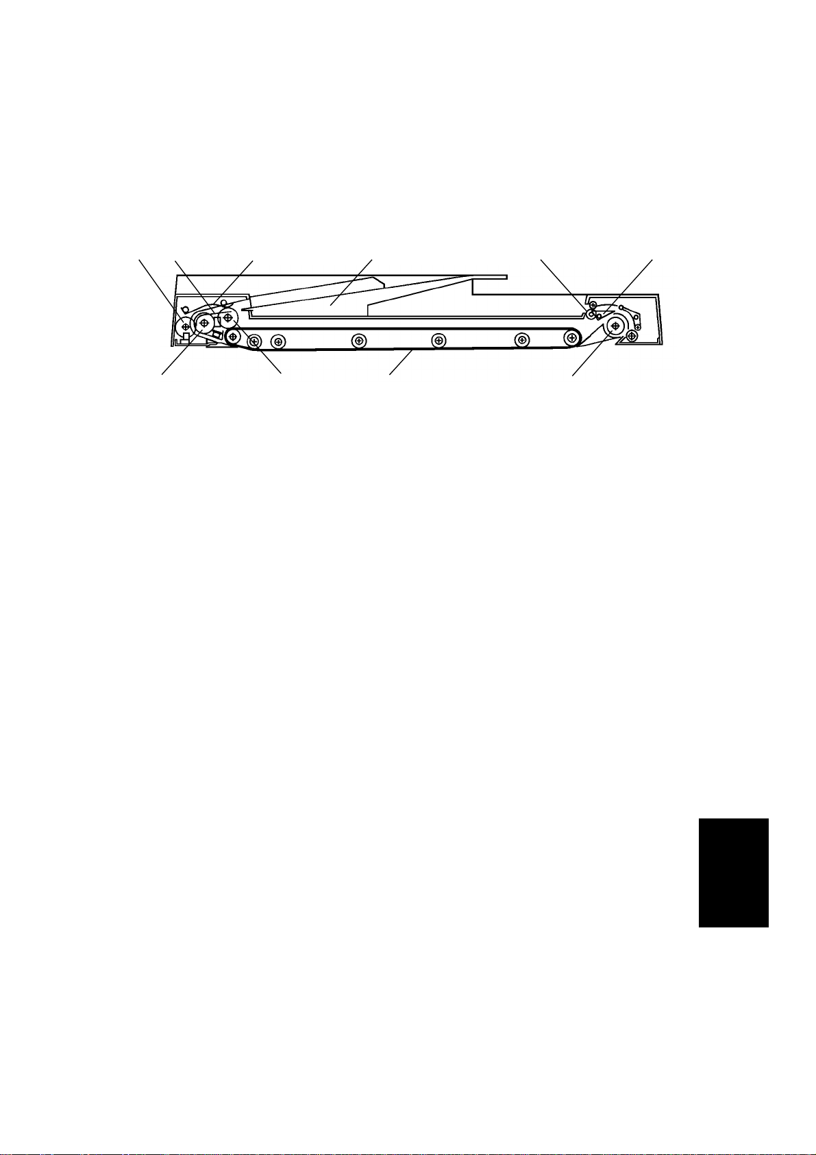
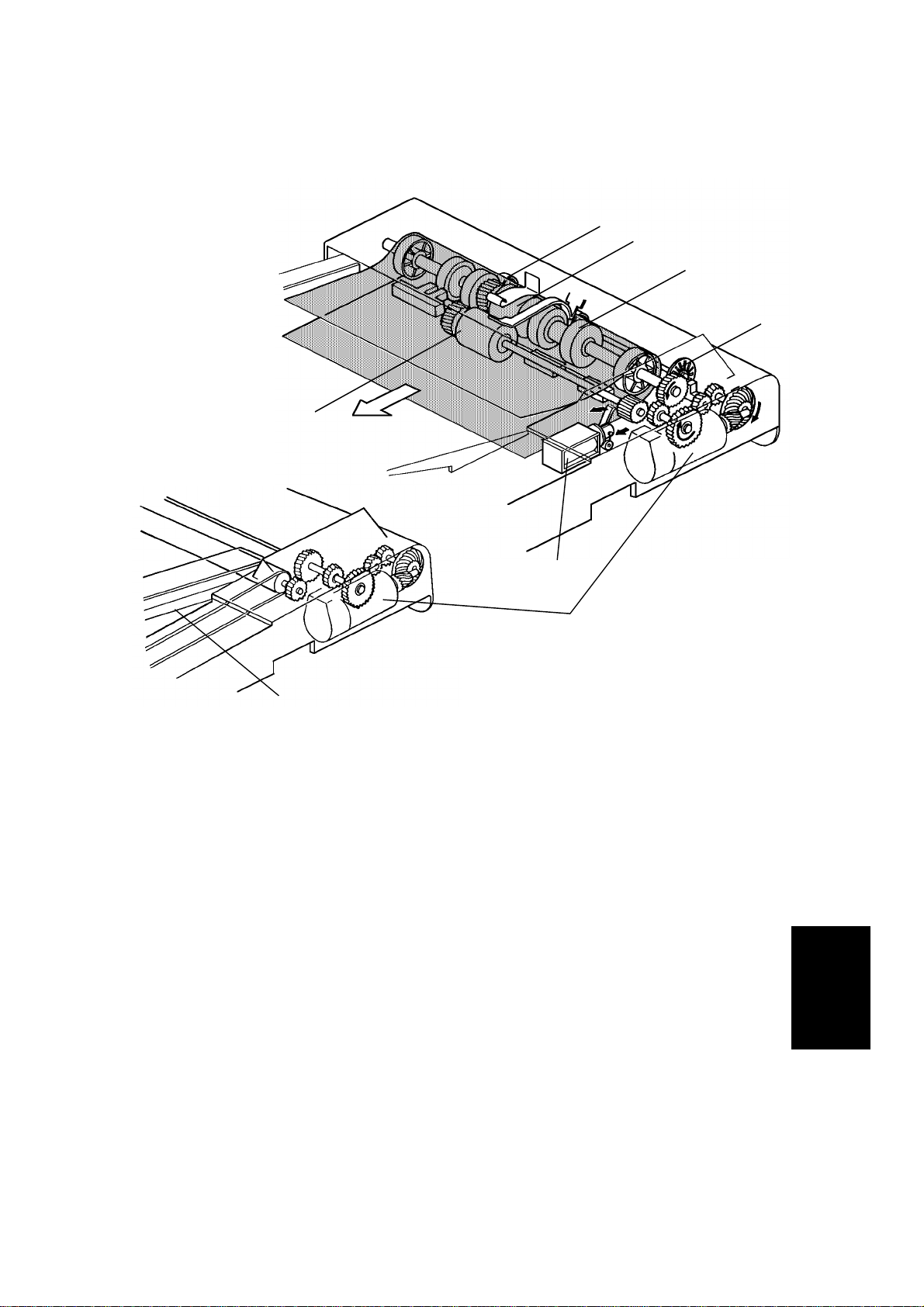
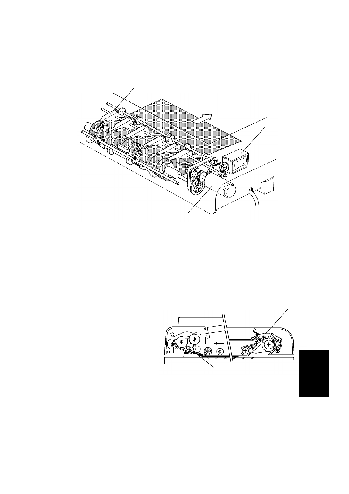
1.2 MECHANICAL COMPONENT LAYOUT
1
2
10
3
9
4
8
5
6
7
1. Pulse Generator Disk 6. Inverter Pawl
2. Friction Belt 7. Inverter Roller
3. Pick-up Lever 8. Transport Belt
4. Original Table 9. Pick-up Roller
5. Exit Roller 10. Feed Roller
Feeder
Document
3
Page 5

OVERALL MACHINE INFORMATION 1 February 1994
1.3 ELECTRICAL COMPONENT DESCRIPTIONS
SYMBOL NAME FUNCTION LOCATION
Motors
M1 Belt Drive Motor DC servomotor that drives to the transport belt
and feed-in system (pick-up roller, feed roller,
pull-out roller and relay roller).
M2 Feed-out Motor DC servomotor that drives the feed-out unit of
the DF.
Solenoids
SOL1 Pick-up Solenoid Energizes to press the pick-up lever against the
stack of originals in preparation for original
feed-in.
SOL2 Feed-in Solenoid Turns on to engage the feed-in clutch so
rotation is transmitted to the feed roller, pull-out
rollers, and relay rollers.
SOL3 Inverter Solenoid Energizes to invert the original when copying
two sided originals.
SOL4 Stopper
Solenoid
Energizes to down the original stopper of the
copier.
6
11
5
14
10
15
Switches
SW1 Lift Switch Informs the CPU when the DF is lifted and also
serves as the jam reset switch for the DF.
SW2 Original Select
Switch
Sensors
S1 Original Set
Sensor
S2 Registration
Sensor
S3 Original Width
Sensor
S4 Pulse Generator
Sensor
S5 Feed-out Sensor Checks for original misfeeds and sets original
S6 ADF Position
Sensor
Selects thick original mode or thin original
mode.
Informs the copier CPU that originals have
been placed and causes the Insert Original
indicator to go out.
Sets original stop timing and measures original
length.
Determines the width of the originals. 4
Generates pulses used to measure the original
length.
stop timing when in auto reverse mode.
Informs the CPU when DF is being closed so
that APS sensor can begin checking the
original size.
8
13
1
2
3
12
16
Printed Circuit Boards
PCB1 DF Main Board Controls all DF functions. 9
4
Page 6
1 February 1994 OVERALL MACHINE INFORMATION
PCB2 Indicator Panel
Contains operator indicators. 7
Board
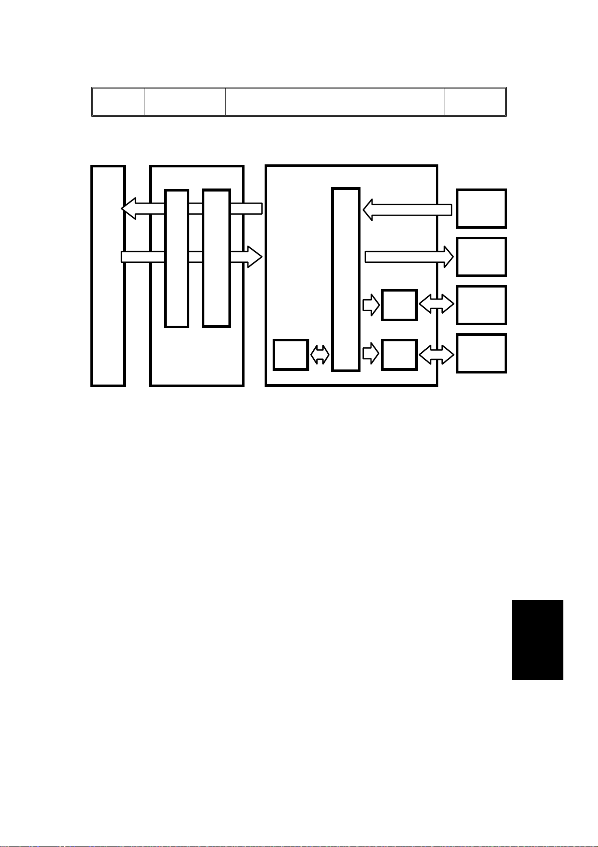
1.4 OVERALL MACHINE CONTROL
Copier
Main Board
RXD
TXD
Copier IPU Board
CPU
Serial
-Parallel
Comverter
DF Main Board
TXD
RXD
ROM
CPU
Driver
IC
Driver
IC
Sensors
Switches
Solenoids
Indicators
Belt Drive
Motor
Feed-out
Motor
The DF CPU monitors the input signals fr om th e sensors and switches, and
energizes the solenoids and the indicator LE Ds direct ly. The belt drive motor
and the feed-out motor are controlled by the DF CPU through their respective
driver ICs.
Also, the DF CPU communicates with the copier using a serial interface. The
exchanged signals are shown in the tables on the next page.
Feeder
Document
5
Page 7

OVERALL MACHINE INFORMATION 1 February 1994
1. DF ⇒ Copier
No. Signal Name Definition
1 Original Set Originals are set on the original table.
2 Copy Start Allows the copier to start copy sequence.
3 Lift Up The DF is lifted.
4 DF Misfeed Misfeed occurs in the DF.
2. Copier ⇒ DF
No. Signal Name Definition
1 Feed-in Requests the DF to feed-in the original.
2 Feed-out Requests the DF to feed-out the or ig ina l .
3 Invert Original Requests the DF to invert the original.
4 Auto Feed Shifts the DF to the auto feed mode.
Original Stay Attempt to use DF but the original from the
5
previous copy run remains on the exposure glass.
6
Page 8

1 February 1994 OVERALL MACHINE INFORMATION
1.5 BASIC OPERATION
1. One-sided Original Feed
When an original is inserted into the DF, the Insert Original indicator light
goes out and the DF informs the copier CPU that originals have been set.
When the Start key is pressed, the copier CPU sends the fe ed-in signal to the
DF. On receipt of this signal, the DF energizes the pick-up solenoid, the
feed-in solenoid, and the belt drive motor in order to feed-in the bottom sheet
of the original stack onto the exposure glass. The pick-up solenoid and the
feed-in solenoid remain energized until the original’s leading edge reaches
the DF registration sensor. The belt drive motor turns off 2,088 encoder
pulses after the original’s leading edge passes the DF registration sensor.
While feeding the original, the DF regi stra tion sensor and the paper width
sensor check the original size.
Shortly before the belt drive motor turns off, the DF CPU sends the copy start
signal to the copier. On receipt of the signal, the copier CPU starts the copy
cycle.
When the scanner reaches to th e r et urn posit i on , th e cop i er CPU sen ds th e
feed-out and the feed-in signals to the DF CPU in order to exchange the
original with the next original.
When the scanner comes to the r et urn posit i on aft er scan nin g th e last
original, the copier CPU only sends the feed-out signal in order to feed-out
the last original.
2. Two-sided Original Feed
Unlike one-sided original feed, the back side of the original must be copied
first to keep the originals and cop i es in th e cor rect order.
During original feed-in, the sequence is the same as for one-sided feed;
however, the DF CPU also energizes the feed-out motor and the inverter
solenoid a short time after the original’s leading edge has passed the DF
registration sensor. The belt drive motor continues to feed the original until
140 milliseconds after the original leading’s edge passes the feed-out sensor.
At this point the inverter mechanism inverts the original, in preparation for
copying the back side. Then the belt drive m ot or reve r ses an d th e or ig ina l is
fed towards the original stopper and is stopped at the correct position on the
exposure glass. The DF CPU sends the copy start signal a short time after
the original’s trailing edge has passed the feed-out sensor.
Feeder
Document
When the scanner reaches to th e r et urn posit i on , th e cop i er CPU sen ds th e
invert original signal to the DF CPU in order to make a copy of the front side.
The original is inverted in the same way as for back side copying.
7
Page 9

OVERALL MACHINE INFORMATION 1 February 1994
3. Semi-automatic Document Feed
If a single original is inserted into th e or ig ina l tab le an d cop i ed , th e DF shifts
to the semi-automatic fe ed mo de and light s the Aut o Fee d ind icator. The
Auto Feed indicator remains on for five seconds after the copier main motor
stops. If another origina l is inser te d with in th at five-second period, it is
automatically fed and copied.
8
Page 10
1 February 1994 DETAILED SECTION DESCRIPTION
2. DETAILED SECTION DESCRIPTION
2.1 ORIGINAL FEED
2.1.1 Original Pick-up
[B]
[C]
[A]
After setting the origina l s on the or ig ina l tab le, the originals contact the feele r
[A] of the original set sensor an d cau se th e feeler to move out of the sensor.
The DF then sends the original set signal to the copier CPU to inform it that
the DF will be used. When the Start key is pressed, the pick-up solenoid [B]
is energized. The original stack is then pressed between the pick-up lever [C]
and pick-up roller [D]. The rotation of the pick-up roller advances the bottom
original.
[D]
[A]
Feeder
Document
9
Page 11
DETAILED SECTION DESCRIPTION 1 February 1994
2.1.2 Original Separation
[B]
[A]
[B]
[C]
[A]
The feed roller [A] and the friction belt [B] are used to feed-in and separate
the originals [C]. Only the bottom original is fed because the friction belt
prevents any other originals from feeding.
Original feed starts when the feed roller starts turning and advances the
bottom original of the stack. The feed roller moves the original past the
friction belt because the drivin g fo r ce of the feed roller is greater than t he
resistance of the friction belt. The friction belt prevents multiple feeds
because the resistance of the friction belt is grea ter than the friction between
original sheets.
10
Page 12
1 February 1994 DETAILED SECTION DESCRIPTION
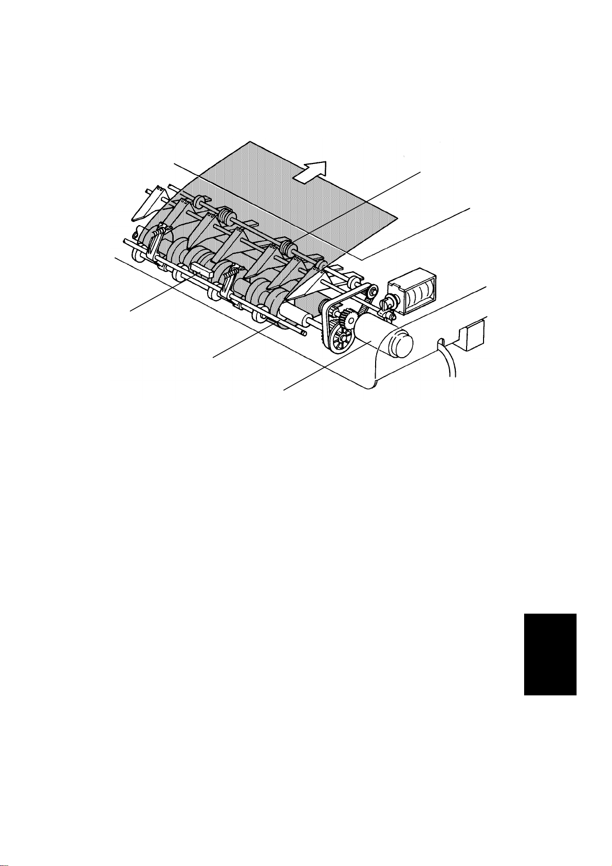
2.1.3 Original Feed-in Mechanism
[E]
[C]
[D]
[H]
[B]
[G]
[A]
[F]
The belt drive motor [A] drives th e pick- u p rolle r [B] , th e fe ed roller [C], the
pull out roller [D], the relay roller [E], and tra nsp ort belt [F] via a feed clutch
and a gear train.
The pick-up solenoid and feed-i n [G ] solenoids are energized 100
milliseconds after the Start key is pressed. Then 200 milliseconds after the
solenoids are energized, the belt drive motor starts turning. The pulse
generator disc [H] always turns when the belt drive motor is on.
2,088 encoder pulses of the belt drive motor after the original’s leading edge
passes the registration sensor, the relay rollers and the transport belt stop
turning.
Feeder
Document
11
Page 13
DETAILED SECTION DESCRIPTION 1 February 1994
2.1.4 Original Size Detection
[C]
[B]
[A]
The DF determines original size (both width and length) through the use of
the original width sensor [A, rear of DF], registration sensor [A, center of DF],
and pulse generator sensor [B]. The original’s length is calculated by
counting the number of pulses from the pulse generator [C] while the
registration sensor is on.
Original size detection is necessary for the feed-in/feed-out timing of the DF.
12
Page 14
1 February 1994 DETAILED SECTION DESCRIPTION
2.1.5 Original Stopping Mechanism
[A]
[B]
- Original Stopper The original stopper [A] is used to align the edge of the original with the right
original scale when the thick original mode is selected.
When the thin original mode is selected, the original stopper solenoid [B] is
energized 200 milliseconds afrter the original’s leading edge passes the
registration sensor and thus the original stopper is held down until the original
is stopped on the exposure glass.
This is to prevent damaging the original’s leading edge against the original
stopper.
NOTE: a) Before the original stopper moves down to feed out the original
from the exposure glass, the be lt dr ive motor reverses, pauses
slightly, and then turns forward. This is to prevent the original’s
leading edge from being caught between the original stopper and
the exposure glass.
b) The speed of the belt drive m otor drops to 1,300 rpm f r om 2,500
rpm 1,812 pulses after the original’s leading edge passes the
registration sensor. This makes it easier for the mechanism to
stop the original at the correct position on th e exp osur e glass.
Feeder
Document
13
Page 15
DETAILED SECTION DESCRIPTION 1 February 1994
[A]
- Original Select Switch This document feeder has two dif fe r en t ways of st op pin g orig inal at the
correct position on the exposur e gla ss. The y ar e calle d th e "thin original
mode" and the "thick orig ingal mode". The mode used is determined by the
original select switch [A].
1. Thin Original Mode
The original is stopped at the correct position on the exposure glass based
on encoder pulse count. The belt dr ive m ot or sto ps 2, 088 encoder pulses
after the original’s reading edge passes the registration sensor at the
one-sided original mode. When the original is inverted in the inverter section,
the belt drive motor stops 422 encoder pulses after the original’s trailing edge
passes the feed-out sensor. (Exact timing depends on registration
adjustment.) Thin original mode is selected at the factory.
2. Thick Original Mode
When the thick original mode is selected, the original is aligned against the
original stopper. The belt drive motor stays on 21 encoder pulses longer than
when in the thin original mode. When the original is inverted, the belt drive
motor continues to reverse for 52 encoder pulses longer than when in the thin
original mode, and then turns forward for 188 encoder pulses. This forces the
original against the original stopper and th us aligns the edge of the original
with the original stopper.
NOTE: The thick original mode should be used when the customer requires
more correct leading edge registration adjustment and/or complains
of skewed copies. The thin original mode is to prevent the thin
original’s from being bent since they do not have great stiffness.
14
Page 16
1 February 1994 DETAILED SECTION DESCRIPTION
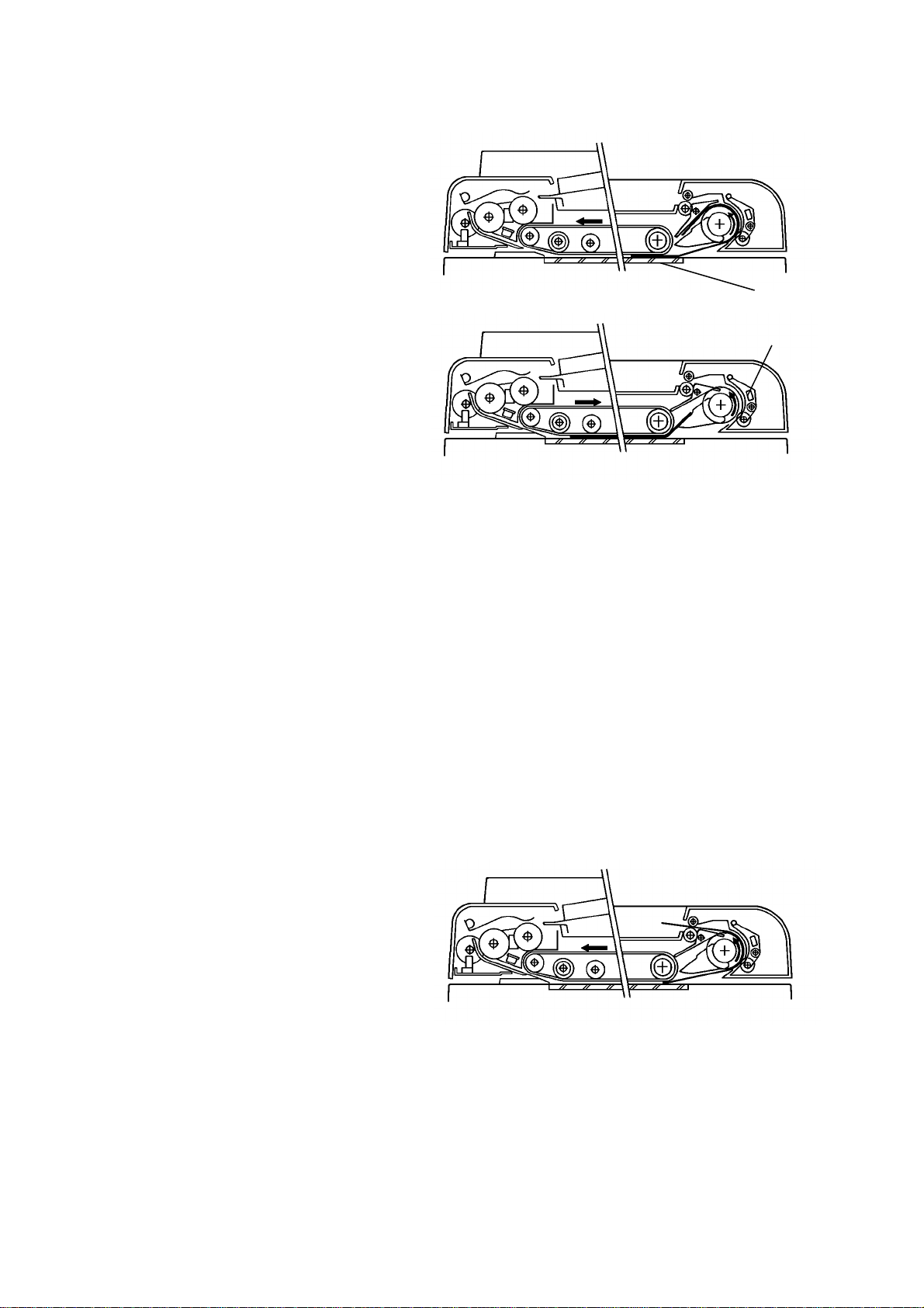
2.1.6 Original Inversion Mechanism
[D]
[C]
The two sided originals are
inverted in the feed-out unit.
1) When the Start key is
pressed, the two sided original
is fed into the feed-in un it,
passing over the DF
registration sensor [A]. The
feed-out motor [B] and the
inverter solenoid [C] turn on
200 milliseconds after the
original’s leading edge passes
the registration sensor. When
the inverter solenoid turns on,
the inverter pawls [D] rotate
counterclockwise.
[B]
[D]
[A]
Feeder
Document
15
Page 17
DETAILED SECTION DESCRIPTION 1 February 1994
2) The original is passes over the
exposure glass [A] and feeds
into the feed-out unit.
[A]
3) The original is directed onto
the exposure glass again by
the inverter pawls. The belt
drive motor now reverses 140
milliseconds after the feed out
sensor [B] turns on. The
transport belt then moves the
original toward the original
stopper.
When the original leading
edge reaches the original
stopper, the belt drive motor
stops. At the same time, the
feed-out motor and the
inverter solenoid turn off.
4) After the reverse side of the
original is exposed, the belt
drive motor, the feed-out
motor, and the inver te r
solenoid turn on, and the
original is fed into the inverter
section. (This is the same as
step 2 above.)
[B]
5) The original is fed onto the
exposure glass again as in
step 3 above. The front side of
the original is then copied.
6) After the front side of the
original has been exposed, the
original is fed out from the DF.
16
Page 18
1 February 1994 DETAILED SECTION DESCRIPTION
2.1.7 Original Feed-out Mechanism
[A]
[D]
[C]
[B]
The exit rollers [A] are driven by inverter motor [B]. When the document
feeder receives the feed out signal from the copier, the transport belt and the
exit rollers start turning simultaneously. The transport belt carries the original
to the inverter rollers [C] and the exit rollers take over the original feed-out.
When the original’s trailing edge passes the feed-out sensor [D], the feed-out
motor drops to half of its normal speed for 220 milliseconds and then stops.
The lower speed prevents uneve n sta cking of originals. For double letter size
originals, the feed-out motor speed does not change due to the length of the
originals.
17
Feeder
Document
Page 19

DETAILED SECTION DESCRIPTION 1 February 1994
2.1.8 Belt Drive Motor Circuit
DF Main Board (PCB 1)
CPU
Speed
Data
ON/OFF
Forward/
Reverse
Driver
IC
PWM
Driver
Circuit
+5V
Phase A
Phase B
CN102-1
CN102-2
CN103-1
CN103-2
CN103-3
CN103-4
Belt Drive
Motor
Encoder
A dc servomotor is used as the belt drive motor. The driver IC controls the
speed of the belt drive motor. The CPU sends the speed data (programmed)
to the driver IC. The driver IC sends the pulse-width -mod ulatio n (PWM)
signal to the driver circuit, which sends the motor drive pulses.
An encoder in the servomotor ha s tw o m agne tic sen s ors that generate two
pulse signals (phase A and B). The drive r IC mo nit or s th e be lt speed and
direction by these pulse signals an d use s t his data to regulate the motor’s
speed.
18
Page 20

1 February 1994 DETAILED SECTION DESCRIPTION
2.1.9 Feed-out Motor Circuit
DF Main Board (PCB 1)
CN104-A2
CPU
High/Low
ON/OFF
Driver
IC
AC Feedback
Voltage
Regulation
Motor
Drive
Circuit
CN104-A15
CN104-B8
CN104-A12
FG
Feed-out
Motor
The DF CPU sends the speed data (high or low) to the driver IC and the
motor drive circuit. The moto r dr ive cir cuit cre at es th e PW M signal and sends
the motor drive pulses to the feed-out motor.
The frequency generator of the feed-out motor makes a very low voltage ac
current which is fed back to the driver IC. The driver IC monitors the
frequency of this ac current and based on the frequency it regulates the
motor speed.
19
Feeder
Document
Page 21

DETAILED SECTION DESCRIPTION 1 February 1994
2.1.10 Input and Output Circuits
Original Set Sensor
P
S
Pulse Generator Sensor
P
S
Registration Sensor
P
S
Original Width Sensor
P
S
Feed-out Sensor
P
S
Original Select SW
CN104-B1
CN104-B9
CN104-B15
CN104-B2
CN104-A9
CN104-B17
CN104-B11
CN104-B16
CN104-A11
CN104-A1
CN104-B10
CN104-A16
DF Main Board (PCB1)
+5V
[ 12]
+5V
[0-12]
[ 5]
[ 5]
+5V
[ 5]
CPU
[ 12]
+24V
[ 24]
+24V
[ 24]
+24V
[0-24]
[0-24]
[0-24]
CN104-A10
CN104-A17
CN104-B6
CN104-A3
CN104-A6
CN104-B14
CN104-B5
CN104-A13
Insert Original
CN104-B12
Auto Feed
CN104-A4
Misfeed
Lift SW (SW1)
Pick-up
SOL
Inverter
SOL
Indicator Panel
P: Photoreceiver
S: Schmitt Trigger Circuit
Feed Out
Motor
[ 5]
[ 24]
GND
[ 24]
[ 24]
Belt Drive
Motor
Copier IPU Board
Original Position
Sensor
CN125-1
CN125-2
CN125-3
[5] Vcc
[ 5] Position Sensor
GND
The above devices are directly contro lled and monitored by the CPU. The
solenoids, motors and indicat or pa ne l are energized with +24 volts. The
sensors and switches are energized with +12 volts or +5 volts.
To energize a solenoid or indicator, the CPU drops the connected trigger line
from +24 volts to LOW. The CPU monitors the input lines of the sensors and
switch to determine when they are activated.
20
Page 22

1 February 1994 DETAILED SECTION DESCRIPTION
2.2 LIFT MECHANISM
[A]
[C]
[B]
[D]
[A]
[F]
[E]
When the document feeder is opened, the lift springs [D] provide enough
force to ensure that the document feeder does not fall onto the exposure
glass. When the document feeder is closed, points [A], [B], and [C] are
aligned and no such force is provided to the document feeder.
[C]
[B]
The lift switch is actuated when the document feeder is closed. The copier
then shifts to the document feeder mode. The lift switch also serves as the
reset switch for document feeder misfeeds.
When a book or thick (maximum thickness 60 mm) original is copied, the DF
acts as a cover for the original as shown in the figure [E]. The lift switch is
turned off during this condition, so the DF does not function. The tension of
spring [F] returns the DF to the normal condition after copying a thick original.
21
Feeder
Document
Page 23

DETAILED SECTION DESCRIPTION 1 February 1994
2.3 ORIGINAL MISFEED SENSING
The copier CPU lights the original misfeed indicator if the previous original
remains on the exposure glass after manual copying an d DF feed is
attempted. When the DF is lifted and the previous original is removed, DF
copying is permitted.
The registration sensor and the feed-out sensor are used for misfeed checks.
The functions of the two sensors are as follows:
1. One-sided original
Registration Sensor
ON check (685 ms)
Feed-out Sensor
OFF check (1,450 ms)
ON check (1,250 ms)
Belt Drive Motor
Feed-out Motor
OFF check (1,250 ms)
If the registration sensor is not actuated within 685 milliseconds after the belt
drive motor starts turning, the Original Misfeed indicator lights (ON check).
If the registration sensor does not turn off within 1,450 milliseconds, the CPU
determines that there has been an original misfeed (OFF check). The
Original Misfeed indicator also lights if the feed-out sensor is not actuated
within 1,250 milliseconds after the belt drive motor starts turning forward (ON
check), or if the feed-out sensor does not turn off within 1,250 milliseconds
after the feed-out sensor turns on (OFF check).
22
Page 24

1 February 1994 DETAILED SECTION DESCRIPTION
2. Two-sided original
Registration
Sensor
Feed-out
Sensor
ON check (685 ms)
OFF check (1,250 ms)
ON check (1,250 ms)
OFF check (1,390 ms)
Belt Drive Motor
Feed-out Motor
Forward
Reverse
The Original Misfeed indicator lights if the registration sensor is not actuated
within 685 milliseconds after the belt drive motor starts turning (ON check), or
if the registration sensor does not turn off within 1,250 milliseconds after the
feed-out motor starts turning (OFF check). If the feed-out sensor is not
actuated within 1,250 milliseconds after the resistration sensor turns off, the
Original Misfeed indicator lights (ON check). The Original Misfeed indicator
also lights if the feed-out sensor does not turn off within 1,390 milliseconds
after the feed-out sensor turns on (OFF check).
The feed-out ON/OFF check is same as for one-sided originals.
23
Feeder
Document
Page 25

Page 26

1. DUMMY
2.
Feeder
Document
Page 27

INSTALLATION 1 February 1994
3. INSTALLATION
3.1 ACCESSORY CHECK
1. Installation Procedure (115 V version only)...........1 pc
2. NECR (115 V version only) ...................................1 pc
3. Original Table ........................................................1 pc
4. Original Stopper.....................................................1 pc
5. DF Supporting Bracket ..........................................1 pc
6. Stopper Bracket.....................................................1 pc
7. Original Stopper Solenoid Assembly.....................1 pc
8. Front Scale Hinge..................................................1 pc
9. Rear Scale Hinge ..................................................1 pc
10. Scale Holder..........................................................1 pc
11. Scale Sheet...........................................................1 pc
12. Installation Screws.................................................15 pcs (total)
Pan Head Screw M5 x 10 ....................................2 pcs
Pan Head Screw M4 x 5 ......................................7 pcs
Pan Head Screw M4 x 6 (Gold: 2, Silver: 1)........3 pcs
Sunken Head Screw M3 x 5.................................1 pc
Philips Screw with Flat Washer M4 x 5................2 pcs
13. Toothed Washer....................................................5 pcs
14. Document Set Decal..............................................1 pc
15. Test Chart (A4)......................................................1 pc
16. Lift Switch Actuator................................................1 pc
17. APS Actuator.........................................................1 pc
18. Envelope for NECR (115 V version only)..............1 pc
19. DF Securing Retainer............................................1 pc
24
Page 28

1 February 1994 INSTALLATION
3.2 INSTALLATION PROCEDURE
[C]
[B]
[D]
[A]
[G]
[E]
[F]
[H]
[I]
1. Unplug the power supply cord of the main system [A], then remove the
platen cover if installed [B] (2 screws, 1 connector).
2. Remove the upper [C] and lower [D] rear covers (6 screws).
3. Remove the front [E] and right [F] scale screw covers.
4. Remove the front [G] and right [H] original scales (2 screws each).
5. Remove the exposure glass [I] as shown in the figure.
25
Feeder
Document
Page 29

INSTALLATION 1 February 1994
[A]
[B]
[C]
[D]
6. Peel off backing and stick the scale sheet [A] on the scale bracket as
shown in the figure.
7. Move the 1st scanner all the way to the left, and connect the original
stopper solenoid connector [B] to the main machine.
8. Install the original stopper solenoid [C] to the scale bracket as shown in
the figure (2 M4 x 5 screws).
9. Secure the rear scale hinge [D] as shown in the figure (1 M4 x 5 screw).
NOTE: Make sure the rear scale hinge leg is installed under the scale
bracket.
26
Page 30

1 February 1994 INSTALLATION
[B]
[C]
[A]
10. Attach the scale holder [A] under the front scale hinge [B], and set the
original stopper [C] in place as shown in the fig ure.
11. Set the original stopper to the rear scale hinge, and secure the front scale
hinge as in the figure (1 M3 x 5 sunken head screw).
NOTE: Make sure the front scale hinge leg is installed under the scale
bracket.
12. Move the 1st scanner back to its ho me po sitio n.
13. Reinstall the exposure glass.
Feeder
Document
27
Page 31

INSTALLATION 1 February 1994
[B]
[C]
[A]
[D]
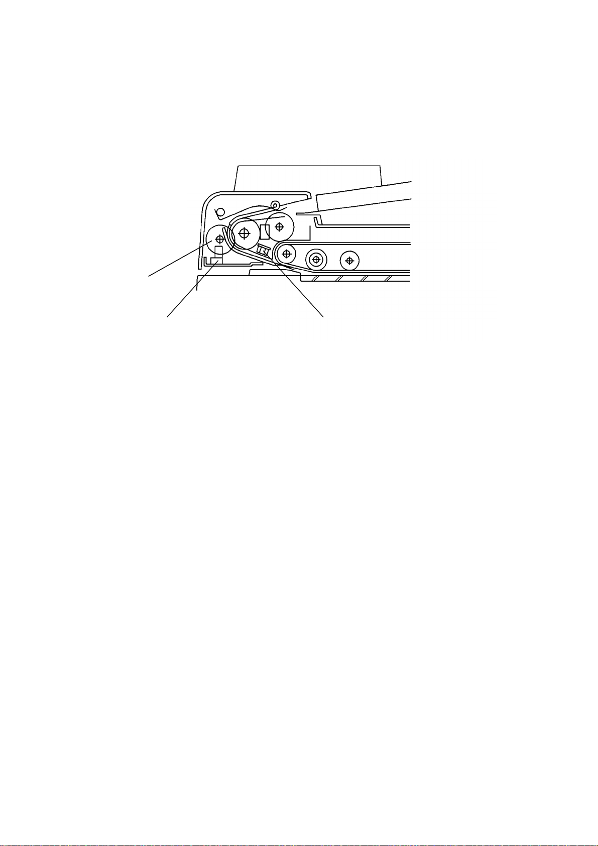
14. Check and adjust the original stopper.
Adjusting standard:
a) The top of the original stopper [A] must be 1.5 to 3.0 mm higher than
the exposure glass [B]. If not, adjust the solenoid stroke by moving the
two screws [C].
b) Press down the original stop pe r [A] and conf ir m tha t th e to p of t he
original stopper is 0.5 to 2.5 mm lower than the exposure glass [D].
15. Reinstall the following parts:
a) Front original scale (2 M3 screws).
b) Front screw covers.
28
Page 32

1 February 1994 INSTALLATION
[H]
[C]
[B]
[G]
[A]
[F]
[D]
[E]
16. Remove the strip of tape an d th e pla stic ba g fr o m the DF harne ss.
17. Install the DF supporting bracket [A] (2 M5 x 10 screws, 2 toothed
washers).
NOTE: There are three holes on both sides of the DF supporting bracket.
Use the center holes for standard installation.
18. Install the DF unit [B] on the DF supporting bracket (2 M4 x 5 screws with
flat washer, 2 toothed washers).
NOTE: Insert the positioning pins [C] of the DF into the center holes [D]
of the support bracket, then slide the DF to the right.
19. Install the lift switch actuator [E] and the APS actuator [F] (1 M4 x 5 screw
each). Confirm that both actuators enter the slots when the DF is lowered.
20. Remove the shipping collar [G].
21. Lower the DF, and install the DF stopper bracket [H] (2 M4 x 5 screws).
Feeder
Document
29
Page 33

INSTALLATION 1 February 1994
[F]
[E]
[G]
[B]
[A]
[C]
[D]
[H]
22. Connect the harness of the 3P [A ] an d 4P [ B] conn ect or s as sho w n in th e
figure.
23. Mount the harness bracket [C] (2 M4 x 6 gold screws).
24. Secure the DF ground wire [D] to the harness bracket as shown (1 M4 x 6
silver grounding screw and toothed washer).
25. Remove the IPU board cover [E] (3 screws).
26. Secure the fiber cable [F] to th e 3 clamp s , an d con ne ct it to t he I PU bo ard
CN308.
27. Remove the plastic cap [G] from the rear upper cover [H] to make a hole
for the DF harness.
28. Reinstall all the covers.
NOTE: Do not pinch the fiber optics cable when reinstalling the rear upper
cover.
30
Page 34

1 February 1994 INSTALLATION
[B]
[A]
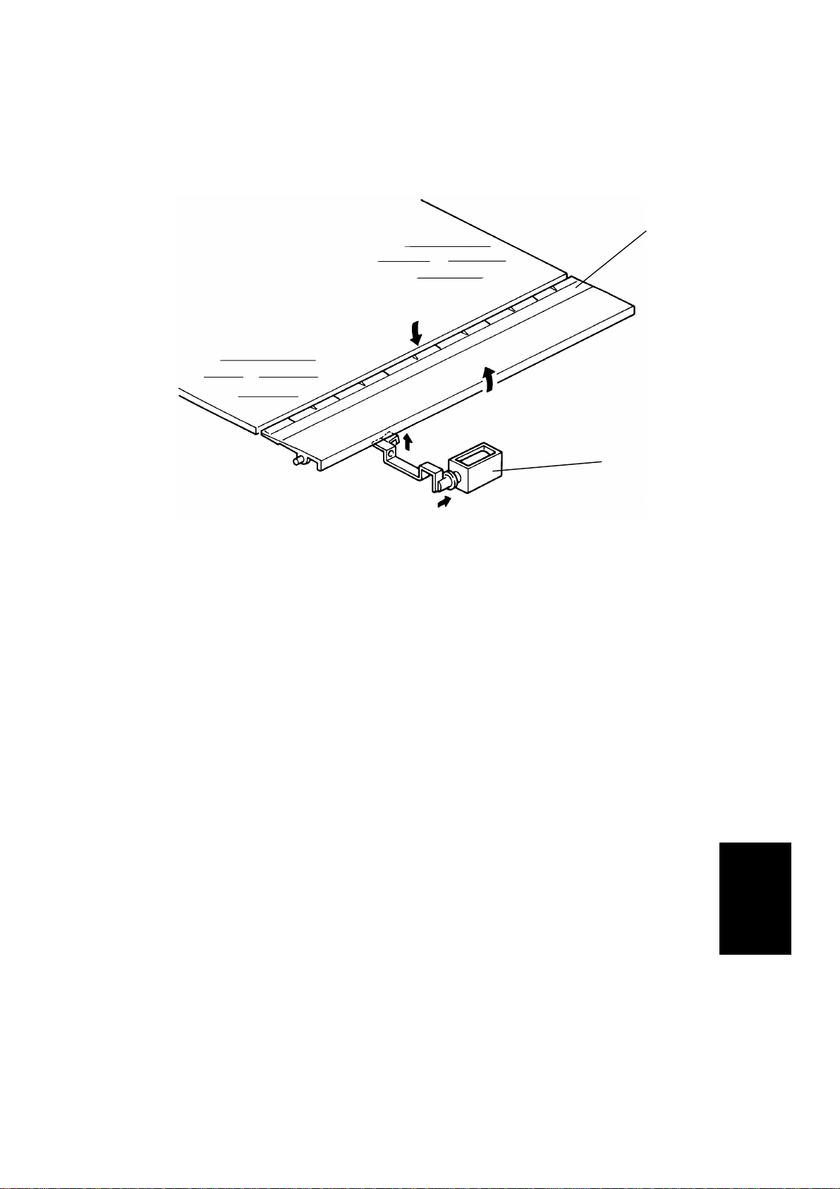
29. Insert the original table [A].
30. Stick the document set decal [B] to the DF.
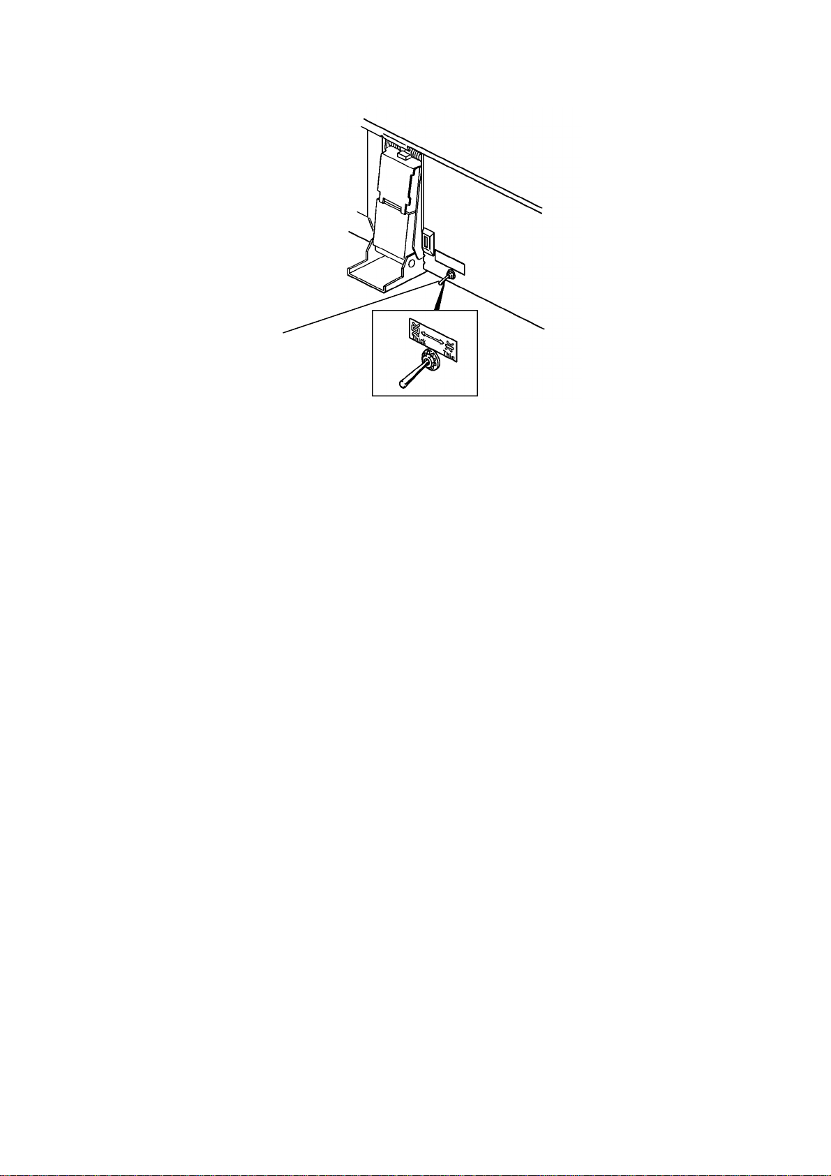
31. Lift up the DF unit and select the thin mode on the original paper
thickness select switch.
32. Plug in the power supply cord and turn on the copier main switch.
33. Check machine operation and copy quality.
Feeder
Document
31
Page 35

INSTALLATION 1 February 1994
[A]
[D]
[B]
Transport Direction
[C]
Transport Direction
34. Check the original skew [A], the original leading edge registration [B]
(both one-sided and double-sided copies), and the original side edge
registration [C] according to the following step s:
35. DF height adjustment:
1) Using the DF test chart, make a copy in the pla te n mod e ( 8
" x 11"/A4
1/2
width).
2) Confirm that the original select switch is in the thin mode and again
using the test chart, make a copy in the DF mode (8
" x 11"/A4 width).
1/2
3) Compare both copies and confirm that there is no skew between them.
4) If there is skew, adjust the magnet catch positions so that the rubber
pad [D] is in contact with the front original scale (2 screws each), after
removing the DF grip (4 screws).
32
Page 36

1 February 1994 INSTALLATION
36. Original leading edge registration adjustment:
1) Using the DF test chart, make copies in both platen and DF (thin
original) modes.
2) Compare the leading edge registration of both copies, and check that
the difference between the two copies is within 2.5 mm.
3) If the difference is more than 2.5 mm, remove the DF main PCB cover
(1 screw) and adjust VR102 on the DF main PCB un til the leading
edge registration is within spe cifica tio n.
NOTE: Turning VR102 clockwise results in stopping the original later
(moving to the right).
4) Using the DF test chart, make a copy in the DF two sided-original
mode. (Insert the original face down.)
5) Compare the leading edge registration with that of the platen cover
mode copy, and check that the difference between the two copies is
within 3.50 mm.
6) If out of specification, adjust VR103 on the DF main PCB until the
leading edge registration is corre ct.
NOTE: Turning VR103 clockwise results in the original stopping later
(moving to the left).
37. Original side edge registration:
1) Using the DF test chart, make copies in both platen and DF modes.
2) Compare the side edge registration of both copies, and confirm that
the difference between the tw o cop ies is wit hin 0 ± 2 mm (in two-sided
mode 0 ± 3 mm).
3) If it is not, adjust the side edge registration using SP6-6.
NOTE: Using SP6-6, the side edge registration can be changed from
–9 to +9 mm, in 0.5 mm steps. Setting the SP6-6 to t he pl us
direction results in the copy image shift i ng to th e lef t an d vice
versa.
38. Confirm the customer’s requests, as the following functions can be
selected if necessary:
1) Each Original Size Detection: SP6-2
2) Sort Priority: SP6- 3 (wh en opt ion al sor t er installed)
3) Odd Number Duplex Copy: SP6-5
Feeder
Document
4) Thick Original Mode: Original Paper Thickness Switch
33
Page 37

SERVICE TABLES 1 February 1994
4. SERVICE TABLES
4.1 TEST POINTS
NUMBER FUNCTION
TP101
TP102
TP103
TP104
TP105
TP106
TP107
Factory use
+5 V
GND
Factory use
+12 V
+24 V
Factory use
4.2 VARIABLE RESISTORS
NUMBER FUNCTION
VR101 Belt drive motor speed adjustment.
VR102
VR103
VR106 Factory use (never adjust this VR).
Original leading edge regist r at ion adju stm e nt
(one-sided thin original mode).
Original leading edge regist r at ion adju stm e nt
(two-sided thin original mode).
4.3 LEDs
NUMBER FUNCTION
LED101
LED102
LED103
LED104
LED105
LED106 Lights when the lift sensor is turned on.
LED107
Lights when the registration sensor is
activated.
Goes out when the original width sensor is
activated.
Goes out when the feed-out sensor is
activated.
Lights when the pulse gene r at or sen s or is
activated.
Lights when the original set sensor is
activated.
Goes out when the original select switch is
turned on (when the thin original mode is
selected).
34
Page 38

1 February 1994 SERVICE TABLES
4.4 DIP SWITCHES
DPS 101
FUNCTION
-1 -2 -3 -4
1 0 0 0 Normal mode
1 0 0 1 One-sided free run: SW101 - ON
0 1 0 1 Two-sided free run: SW101 - ON
0011
Solenoid test: SW101 - solenoids ON
SW102 - solenoids OFF
1101Motor test
1 1 1 1 All indicators ON
0: OFF 1: ON
NOTE: a) To use all functions, the DPS101 must be set to the normal
mode when the main switch is turned on. At this time, the
initial sequence between the copier and the DF will take place.
b) To use all functions except for the solenoid test mode, the lift
switch must be turned on.
c) To use the one and two-sided free run modes, all sensors
must be activated in the normal manner. Therefore, place the
DF in the normal working position (dow n) and place paper on
the original table. Then, turn on SW101 at the rear side of the
DF.
35
Feeder
Document
Page 39

REPLACEMENT AND ADJUSTMENT 1 February 1994
5. REPLACEMENT AND ADJUSTMENT
5.1 FEED-IN UNIT
5.1.1 Transport Belt Replacement
[C]
[H]
[I]
[A]
[D]
[B]
1. Turn off the main switch and remove the grip [A] (4 screws).
2. Remove the DF main PCB cover [B] (1 screw, 1 connector).
3. Open the entrance guide [C] and remove the tra nsport belt assembly [D]
(5 screws).
36
Page 40

1 February 1994 REPLACEMENT AND ADJUSTMENT
[G]
[F]
[E]
4. Remove the 2 tension springs [E] and pull off the transpo r t belt [F].
NOTE: a) When installing the transport belt, make sure the belt lies
between the belt guide space r s [G] .
b) When installing the transport belt assembly [D], make sure the
positioning pin correctly fit s in the DF fram e [H], and hold open
the exit guide [I] to prevent the mylar strip from becoming
damaged.
Feeder
Document
37
Page 41

REPLACEMENT AND ADJUSTMENT 1 February 1994
5.1.2 Feed-in Unit Removal
[B]
[A]
1. Turn off the main switch.
2. Remove the transport belt assembly. (See the Transport Belt
Replacement section.)
3. Remove the belt drive motor cover [A] (4 screws).
4. Remove the feed-in unit [B] (4 screws, 7 connectors).
38
Page 42

1 February 1994 REPLACEMENT AND ADJUSTMENT
5.1.3 Pick-up Roller Replacement
[A]
[B]
[C]
[D]
1. Turn off the main switch.
2. Remove the feed-in unit. (See the Feed-in Unit Removal section.)
3. Remove the lower entrance guide [A] (2 screws).
4. Remove the original set sensor assembly [B] (1 screw), without
disconnecting the connector.
5. Remove the pick-up roller [C] (3 E-rings, 1 bushing, 1 gear).
NOTE: a) Be careful not to loosen the positioning pin [D].
b) When installing the roller, make sure the positioning pin is
correctly inserted in the cut-out of the roller.
c) When installing the gear, make sure the flat side of the gear is
facing away from the roller.
Feeder
Document
39
Page 43

REPLACEMENT AND ADJUSTMENT 1 February 1994
5.1.4 Feed-in Clutch Lubrication
[B]
[A]
1. Turn off the main switch.
[D]
[C]
2. Remove the original set sensor assembly. (See the Pick-up Roller
Replacement section.)
3. Remove the feed-in solenoid lever spring [A].
4. Remove the pick-up roller assembly [B] (2 E-rings, 2 bushings).
5. Disassemble and lubricate the feed clutch [C] (1 E-ring) with Mobil Temp.
78.
NOTE: a) Be careful not to loosen the positioning pin [D].
b) When installing the feed clutch, make sure the positioning pin
is correctly inserted in the cut-out of the clutch.
40
Page 44

1 February 1994 REPLACEMENT AND ADJUSTMENT
5.1.5 Pick-up Solenoid Adjustment
[E]
[C]
[D]
[B]
[F]
[A]
1. Turn off the main switch.
2. Place several sheets of paper [A] over the exposure glass area.
3. Lower the feed-in unit (see the Feed-in Unit Removal section) without
disconnecting the seven connectors.
4. Turn on the main switch.
NOTE: When the main switch is turned on, the DPS101 [B] setting on
the DF main PCB must be as follows:
1 = ON 3 = OFF
2 = OFF 4 = OFF
This is so that the initial check sequence can take place.
41
Feeder
Document
Page 45

REPLACEMENT AND ADJUSTMENT 1 February 1994
5. Turn off DPS101-1, then turn on DPS101-3 and 4 [B].
6. Loosen the screw fixing the pick-up solenoid [C].
7. Place the 0.15 mm thickn ess gauge [D] between the plu nger and the
solenoid.
NOTE: Two sheets of paper (20 lb/75 g/m2) can be used instead of a
thickness gauge.
8. While holding the gauge, pr ess SW101 [E] on the DF main PCB to
engage all DF solenoids.
9. Keeping a 0.15 mm gap, mo ve th e sole no id slowly un til th e pick- u p leve r
is just touching the pick-up roller.
10. Secure the screw fixing the pick-up solenoid [C].
11. Press SW 102 [F] to turn of f th e sole no ids.
12. Set the DPS101 [B] for normal mode (1 = ON, 2 = OFF, 3 = OFF, 4 =
OFF).
13. Turn off the main switch and rea ssemble the DF.
14. Check the original feed-in operation.
42
Page 46

1 February 1994 REPLACEMENT AND ADJUSTMENT
5.1.6 Feed Roller Replacement
[D]
[C]
[A]
[B]
1. Turn off the main switch.
2. Remove the lower entrance guide. (See the Pick-up Roller Replacement
section.)
3. Loosen the front bracket [A] (2 screws).
4. Release the feed roller shaft [B] from the front bracke t ( 1 E-r in g,
1 bearing).
5. Remove the feed roller [C] (3 E-rings, 1 side roller, 1 pull-out roller).
NOTE: a) Take care not to lose the positioning pins [D].
b) When installing the feed roller, make sure the gear side of the
roller faces the front (see illustration).
c) When installing the side and pull-out rollers, make sure the
positioning pins are correctly inserted in the cut-outs of the
rollers.
Feeder
Document
43
Page 47

REPLACEMENT AND ADJUSTMENT 1 February 1994
5.1.7 Feed-in Solenoid Adjustment
[B]
[C]
[A]
[D]
1. Turn off the main switch.
2. Place several sheets of paper [A] over the exposure glass area.
3. Lower the feed-in unit (see the Feed-in Unit Removal section) without
disconnecting the seven connectors.
4. Check that DPS101 [B] is set for the normal mode (1 = ON, 2 = OFF, 3 =
OFF, 4 = OFF).
5. Turn on the main switch.
6. Turn off DPS101-1, then turn on DPS101-3 and 4 [B].
7. Loosen the 2 screws securing the feed-in solenoid [C].
8. Press SW101 on the DF main PCB (to engage all DF solenoids) and
adjust the position of the solenoid until the gap [D] (see illustration) is
within 1.0 to 2.0 mm.
9. Press SW102 on the DF main PCB to turn off all DF solenoids.
10. Set the DPS101 [B] for normal mode (1 = ON, 2 = OFF, 3 = OFF, 4 =
OFF).
11. Turn off the main switch and rea ssemble the DF.
44
Page 48

1 February 1994 REPLACEMENT AND ADJUSTMENT
5.1.8 Registration Sensor and Original Width Sensor Replacement
[C]
[B]
[A]
[F]
[E]
[G]
[D]
1. Turn off the main switch.
2. Remove the pick-up roller. (See the Pick-up Roller Replacement section.)
3. Remove the sensor holder plate [A] with the 2 sensors (2 screws).
4. Remove the registration sensor [B] and the original width sensor [C] (1
screw, 1 connector each).
NOTE: The registration sensor and the original sensor can be cleaned
as follows:
Open the DF and release the lower guide plate [D] of the feed-in
unit by pushing the lever for misfe d paper removal. Then, clean
the 2 sensors [E] from the cutout portion of the plastic guide plate
[F]. Also, clean the black rubber sea ls [ G] insta lled on th e lowe r
guide plate using a blower br ush.
Feeder
Document
45
Page 49

REPLACEMENT AND ADJUSTMENT 1 February 1994
5.1.9 Friction Belt Replacement
[A]
[B]
[C]
1. Turn off the main switch.
2. Remove the seal cover [A] on top of the DF cover.
3. Remove the friction belt assembly [B] (1 screw).
4. Remove the friction belt [C] (2 springs, 1 pin) .
NOTE: If the seal cover becomes dirty or deformed , repl ace it with a new
one.
46
Page 50

1 February 1994 REPLACEMENT AND ADJUSTMENT
5.1.10 Belt Drive Motor Speed Adjustment
[B]
[A]
[D]
[C]
1. Remove the DF main PCB cover [A] (1 screw), without disconnecting the
connector.
2. Turn on DPS 101-2 and -4.
3. While turning on the lift switch manually, adjust the belt drive motor speed
to within 2,570 to 2,630 rpm using VR101 [B], so that both the Insert
Original indicator [C] and the Auto Feed indicator [D] go out.
47
Feeder
Document
Page 51

REPLACEMENT AND ADJUSTMENT 1 February 1994
NOTE: a) When the Insert Original indicator lights , turn VR101
clockwise to reduce the motor speed.
b) When the Auto Feed indicator lights, turn VR101 counter
clockwise to raise the motor speed.
c) Confirm that both indicators remain off for approximately 5
seconds, in order to steady the motor speed.
d) This procedure must be perfor m e d whe n rep l acin g th e DF
main PCB.
4. Set DPS 101 for normal mode (1 = ON, 2 = OFF, 3 = OFF, 4 = OFF).
48
Page 52

1 February 1994 REPLACEMENT AND ADJUSTMENT
5.2 FEED-OUT UNIT
5.2.1 Feed-out Unit Removal
[A]
[C]
[B]
1. Turn off the main switch.
2. Remove the DF grip [A] (4 screws).
3. Remove the feed-out motor cover [B] (4 screws).
4. Remove the feed-out unit [C] (4 screws, 1 ground wire, 3 connect ors).
Feeder
Document
49
Page 53

REPLACEMENT AND ADJUSTMENT 1 February 1994
5.2.2 Feed-out Sensor Replacement
[A]
[B]
1. Remove the feed-out unit. (See the Feed-out Unit Removal section.)
2. Remove the sensor holder plate [A] with the sensor on (1 screw, 1
connector).
3. Remove the feed-out sensor [B] from the plate (1 screw).
50
Page 54

1 February 1994 REPLACEMENT AND ADJUSTMENT
5.2.3 Timing Belt Tension Adjustment
[A]
[B]
1. Turn off the main switch.
[D]
[C]
2. Remove the feed-out unit. (See the Feed-out Unit Removal section.)
3. Unhook the rear spring [A] of the feed-out unit entrance guide.
4. Loosen the 2 screws securing the feed-out motor assembly [B].
5. With a tension gauge, pr ess th e tim in g be lt [C] in the center between the
feed-out roller drive pulley and the inverter roller drive pulley.
6. Adjust the position of the feed-out motor assembly so that the slack of the
timing belt becomes within 0.5 to 2.0 mm [D], when the tension gauge
indicates 100 g.
Feeder
Document
51
Page 55

REPLACEMENT AND ADJUSTMENT 1 February 1994
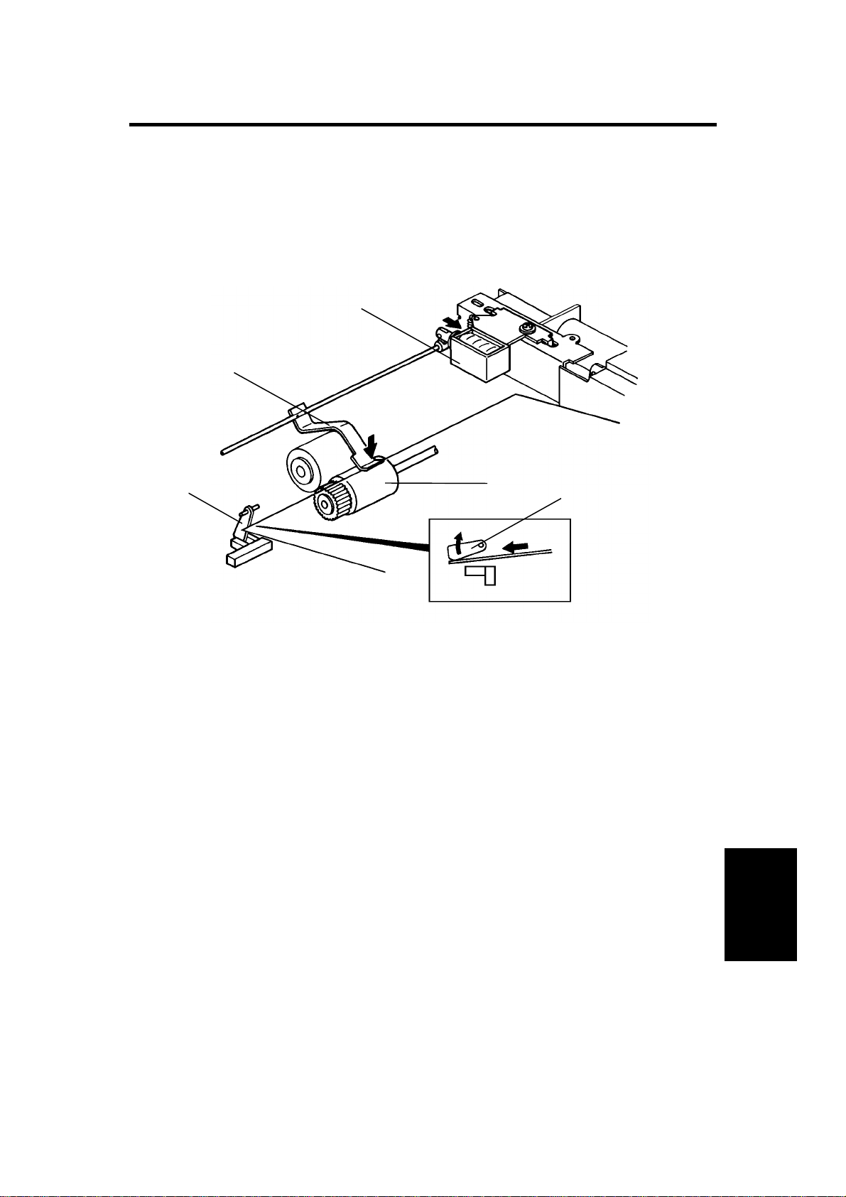
5.2.4 Inverter Solenoid Adjustment
[B]
[A]
[D]
[F]
[C]
[E]
1. Turn off the main switch.
2. Place several sheets of paper [A] over the exposure glass area.
3. Lower the feed-out unit (see the Feed-out Unit Removal section) without
disconnecting the three connectors.
4. Turn on the main switch.
NOTE: When the main switch is turned on, the DPS101 [B] setting on
the DF main PCB must be as follows: 1 = ON, 2 = OFF, 3 = O FF,
4 = OFF.
5. Turn off DPS101-1, then turn on DPS101-3 and 4 [B].
6. Loosen the screw securing the inverter solenoid [C].
7. Press SW101 [D] on the DF main PCB (to engage all DF solenoids), and
adjust the position of the solenoid until the gap [E] (see illustration) is
within 1.0 to 2.0 mm.
8. Press SW102 [F] on the DF main PCB to turn off all DF solenoids.
9. Set the DPS101 [B] for normal mode (1 = ON, 2 = OFF, 3 = OFF, 4 =
OFF).
10. Turn off the main switch and rea ssemble the DF.
52
Page 56

1 February 1994 REPLACEMENT AND ADJUSTMENT
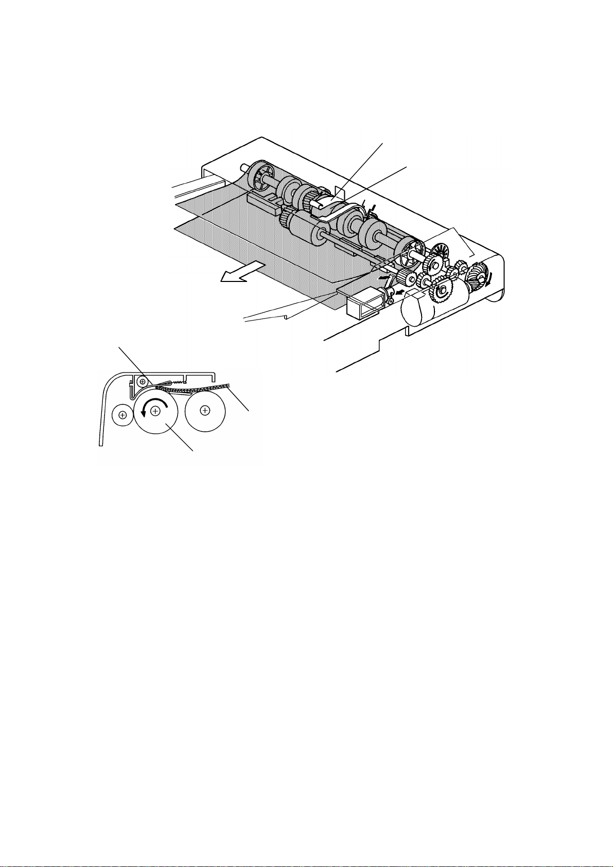
5.2.5 Feed-out Motor Unit and Inverter Roller Replacement
[A]
[D]
[E]
[C]
[F]
[B]
[G]
CAUTION: Be careful not to mix up the springs when removing the
inverter guide plate. Be careful not to loose the positioning
pin [A].
1. Remove the feed out unit. (See the Feed-out Unit Removal section.)
2. Remove the inverter guide plate [B] (1 screw, 2 springs).
3. Remove the inverter solenoid with the bracket on [C] (1 screw).
4. Remove the feed-out motor unit [D] (2 screws), and the timing bel t [E].
5. Remove the inverter roller pulley [F] (1 E-ring).
6. Remove the inverter roller [G] (1 E-ring, 2 bushing).
NOTE: After reinstalling the feed-out motor unit, perform the following
adjustment procedur es.
a) Timing belt tension adjustment.
b) Inverter solenoid adjust m ent.
Feeder
Document
53
Page 57

REPLACEMENT AND ADJUSTMENT 1 February 1994
5.2.6 DF Leading Edge Registration Adjustment
[C]
[B]
[A]
1. Using the DF test chart, make a copy in the pla te n cove r mode (A 4 widt h) .
2. Confirm that the original select switch [A] is in the thin mode and again
using the test chart, make a copy in the DF mode (A4 width).
3. Compare the leading edge registration of both copies, and check that the
difference between the two copies is within 2.5 mm.
54
Page 58

1 February 1994 REPLACEMENT AND ADJUSTMENT
4. If the difference is more than 2.5 mm, remove the DF main PCB cover [B]
(1 screw, 1 connector) and adjust VR102 on the DF main PCB [C] until
the leading edge registration is within specification.
NOTE: Turning VR102 clockwise results in stopping the original later
(moving to the right).
5. Using the DF test chart, make a copy in the DF two sided-original mode.
(Insert the original face down.)
6. Compare the leading edge registration with that of the platen cover mode
copy, and check that the difference between the two copies is within 3.5
mm.
7. If out of specification, adjust VR103 on the DF main PCB until the leading
edge registration is correct.
NOTE: Turning VR103 clockwise results in the original stopping later
(moving to the left).
NOTE: This procedure must be performed when r epl acin g th e DF ma in PCB .
55
Feeder
Document
Page 59

REPLACEMENT AND ADJUSTMENT 1 February 1994
5.2.7 DF Side Edge Registration Adjustment
[C]
[B]
[E]
[D]
[A]
[D]
[E]
1. First check the position of the original path by setting the DF test chart on
the original table.
2. Press the Start key, then press the Clear/Stop key shortly after the DF
test chart is fed.
3. Open the DF carefully, and check the dist an ce be twe en the fr on t side
edge of the DF test chart and the front original scale. If it is 2.0 mm or
more, go to step 5.
4. If the distance is less than 2.0 mm, move the DF supporting bracket [A] to
the left, and then install the DF, the lift switch actuator [B], and the APS
actuator [C] using holes [D].
NOTE: a) If the distance is less, the original might hit the front original
scale, resulting in original misfeeds or skewing.
b) Moving the DF supporting bracke t on e set of ho les at a time
gives a 1.5 mm difference horizontally relative to the position
of the original path.
56
Page 60

1 February 1994 REPLACEMENT AND ADJUSTMENT
5. To adjust the side edge registration, make a copy in platen mode using
the DF test chart.
6. Again using the test chart, make a copy in DF mode.
7. Compare the side edge registration of both copies, and confirm that the
difference between the two copies is within 2.0 mm (in two-sided original
mode, within 3.0 mm).
8. If it is out of specification, adjust the side edge registration using SP
Mode No. 6-6. (For SP Mode access, see the SP Mode list.)
NOTE Using SP Mode No. 6-6, the side edge registration can be
changed from –9 to +9 mm, in 0.5 mm steps. Setting the SP
Mode No. 6-6 to the plus direction results in the copy image
shifting to the left of the copy and vice versa.
9. If the difference is more than 9 mm, move the DF supporting bracket [A]
to the right, then install th e DF, th e lift swit ch act ua to r [B] , an d the APS
actuator [C] using the holes [E]. Then, repeat steps 7 and 8.
57
Feeder
Document
 Loading...