

Page 1

RECIRCULATING DOCUMENT
HANDLER
(Machine Code: A378)
Page 2

23 April 1993 SPECIFICATIONS
1. SPECIFICATIONS
Original Size: Max A3, 11" x 17"
Min A5 lengthwise, 5 1/2 " x 8 1/2"
(No A5 Sideways, 8 1/2 x 5 1/2)
Original Weight: 52~104 g/m
2
(14~28 lb) (ARF)
52~128 g/m2 (14~34 lb) (ADF)
Original Feed Mode: Automatic Feed (ADF)
Automatic Recycle Feed (ARF)
Original Capacity: Max 50 sheets (A4, 8 1/2" x 11")
Original Separation: Feed and Friction Belts system
Original Transport: One flat belt
Original Stop System: DC servo motor control system
Copying Speed: Continuous copy
55 cpm (A4S, 11" x 81/2", 1st feed station)
Single copy
55 cpm (A4S, 11" x 8 1/2", 1st feed statio n)
Number of Cycles
Max 30 times
per Document:
Power Source: 24V (from copier), 5 A
Power Consumption: 70W
Dimensions:
(W x D x H)
645 x 516 x 132 millimeters
(25.4 x 20.4 x 5.2 inches)
Weight: Approximately 18 kg (39.7 lb)
RDH
1
Page 3
11
MECHANICAL COMPONENT LAYOUT 23 April 1993
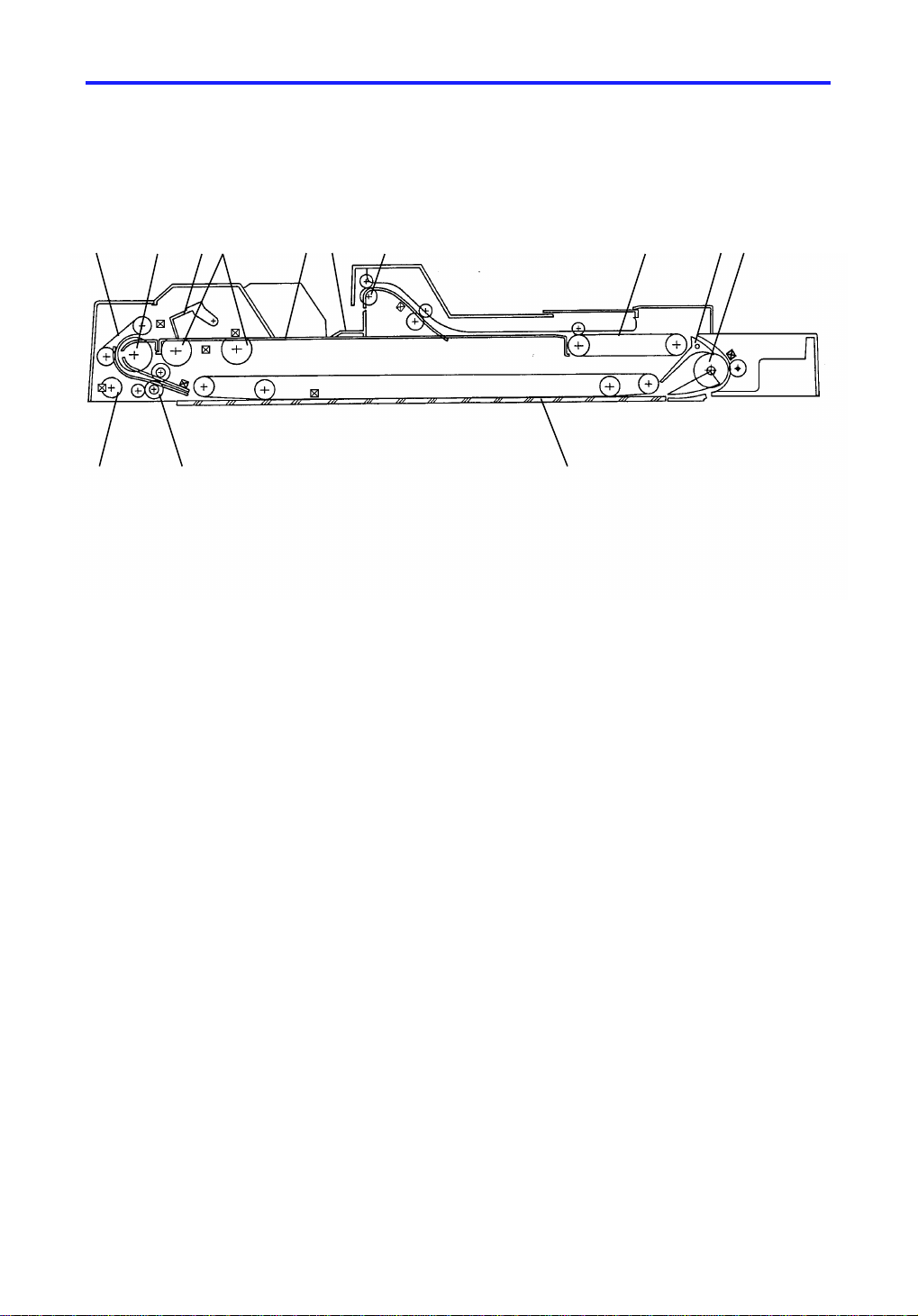
2. MECHANICAL COMPONENT LAYOUT
1
13 12
1. Friction Belts
2. Feed Roller
3. Original Gate
2
34 56 7 8 9
10
8. Exit Relay Belts
9. Inverter Pawls
10. Inverter Roller
4. Pick-up Rollers
5. Original Stacker
6. Push-plate
7. Feed-out Rollers
11. Transport Belt
12. Pull-out Roller
13. Pulse Generator
2
Page 4

23 April 1993 ELECTRICAL COMPONENT DESCRIPTIONS
3. ELECTRICAL COMPONENT DESCRIPTIONS
Symbol Name Function
Motors
M1 Feed-in Motor Drives the feed-in system
(pick-up rollers, feed roller, and
pull-out roller). (dc servo)
M2 Transport Belt Motor Drives the transport belt. (dc
servo)
M3 Inverter Motor Drives the inverter roller and the
exit relay belts.
M4 Feed-out Motor Drives the feed-out unit. 15
M5 Friction Belt Motor Drives the friction belts 21
Solenoids
SOL1 Original Gate
Solenoid
SOL2 Inverter Solenoid E nergizes to invert the original
Energizes to open the orig ina l
gate.
when copying a two-sided
original.
Index
No.
3
4
9
22
8
SOL3 Push Plate Solenoid Energizes to push the stack of
originals to the feed-in section.
Switches
SW1 Lift Switch Informs the copier CPU when the
RDH is lifted and also serves as
the jam reset switch for the RDH.
SW2 Feed-in Unit Safety
Switch
SW3 Feed-out Unit Safety
Switch
Detects if the feed-in unit is set
correctly.
Detects if the feed-out unit is set
correctly.
14
7
23
10
RDH
3
Page 5

ELECTRICAL COMPONENT DESCRIPTIONS 23 April 1993
Symbol Name Function
Sensors
S1 Original Set Sensor Informs the copie r CP U tha t
originals have been placed and
causes the Insert Origin al
indicator to go out.
S2 Recycle Sensor Informs the CPU when the top
original is fed from the original
stacker.
S3 Registration Sensor Sets original stop timing and
measures the original’s length.
S4 Original Width
Sensor
S5 Pulse Generator
Sensor
Determines the width of the
original.
Generates the pu lses use d to
measure the original’s length.
S6 Inverter Sensor Sets original stop timing when in
auto reverse mode.
Index
No.
17
19
17
20
1
11
S7 Feed-out Sensor Checks for original misfeeds. 13
S8 One Turn Sensor Informs the CPU when the
pick-up roller turns one rotation.
S9 RDH Position Sensor Informs the CPU when the RDH
is being closed so that APS
sensor can begin checking the
16
original size.
Magnetic Clutch +
CL1 Feed-in clutch Energizes to rotate the feed roller. 2
Printed Circuit Boards
PCB1 RDH Main PCB Con tro ls all RDH funct ion s. 12
PCB2 Indicator Pane l PCB Contains indicators for t he
operator.
6
5
4
Page 6

23 April 1993 BASIC OPERATION
4. BASIC OPERATION
4.1 ONE-SIDED ORIGINAL FEED
When an original is placed in the RDH, the Set Original indicator goes out
and the RDH informs the copier that originals have been set.
When the Start key is pressed, the copier CPU sends the feed-in signal to the
RDH. On receipt of this signal, the gate solenoid turn s on, ope nin g the
original gate. At the same time the push-plate solenoid and the feed-in motor
turn on. The push-plate an d pick-u p rolle rs mo ve th e en tire stack of originals
to the feed posit ion .
After that, the feed-in mot or sta rts tu rnin g ag ain . The bot to m origin al is f ed in
by the feed roller and the friction belts and de livere d to the exposure glass by
the transport belt.
After a very short period, th e seco nd origin al is also fe d in un til its lea ding
edge reaches the regist rat ion sensor. This is in preparatio n fo r t he next copy
cycle.
When the scanner reaches the return position, the copier CPU sends the
feed-out and the feed-in signals to the RDH in order to feed in the second
original. If the first original is A4/Letter size (side ways fe ed) or smaller, it is
not fed out as the next original is transported to the exposure glass. It is just
moved to the right side of th e exp osure glass. After completing the second
scan, the third original is fed in and the first original is fed out from the unit.
This continues until all origina ls have bee n cop ied .
The originals are stacked on the original table where they wait for the next
copy cycle.
4.2 TWO-SIDED ORIGINAL FEED
Unlike one-sided original feed, the back-side of the orig ina l must be copied
first to keep the originals and copies in correct order.
During original feed-in, the sequence is the same as fo r one-side d feed ;
however, the RDH CPU also energizes the feed-out motor and the inverter
solenoid a short time afte r t he origin al’s leading edge has passed the RDH
registration sensor. The transport belt motor continues to feed the original
until the inverter mechanism inverts the original for the back-side copying.
Then, the transport belt moto r re verse s to feed the origin al towards the scale,
and stops the original at the correct posit ion on the exposure glass.
RDH
When the scanner reaches the return position, the copier CPU sends the
feed-out signal to the RDH CPU. The RDH then inverts the original in th e
same way as for back-side copying .
5
Page 7
FEED-IN DRIVE MECHANISM 23 April 1993
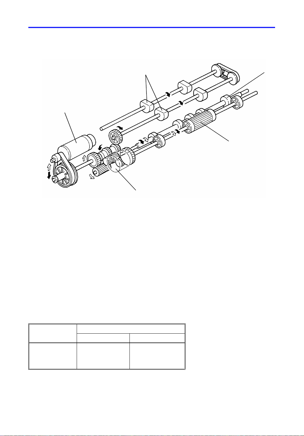
5. FEED-IN DRIVE MECHANISM
[A]
[D]
[B]
[E]
The pick-up rollers [A], feed roller [B], and the pull-o ut rollers [C] are drive n by
the feed-in motor [D] through the timing belt, th e gears and the feed-in clutch
[E].
[C]
-Basic OperationThe feed-in motor is a reversible dc motor. When the feed-in moto r rota tes
forward (counterclockwise), all the rollers turn in the original fee d dire ctio n.
(The feed roller can rotate only when the feed-in clutch is on. )
When the feed-in motor reverses, the pick-up rolle rs stop. However, the feed
roller and the pull-out rolle rs co nt inue turning in the same direct ion.
Roller(s) Feed-in Motor
Forward Reverse
Pick-up
Feed
Pull-out
(* Only when the feed-in clutch turns on, the feed roller rotates.)
On
On/Off
On
Off
On/Off
On
6
Page 8
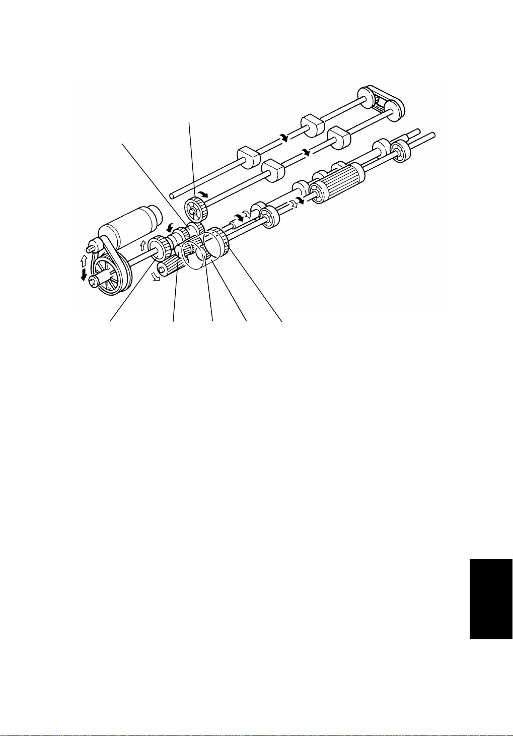
23 April 1993 FEED-IN DRIVE MECHANISM
[G]
[F]
[H]
[I]
[J]
[K]
[L]
When the Start Key is pressed, th e fe ed -in mot or sta rts turning
counterclockwise. Drive is transferred to the pick-up rolle rs thro ug h gears [E ]
and [G] and to the feed-in clutch throu gh gears [H] an d [J] . The timing of the
feed roller rotation is controlled by the feed-in clut ch [K ].
Next, the feed-in motor reverses (clockwise). The pick-up rollers stop turning
due to the one-way bearing inside the gears [F] an d [H] . However, the feed
roller continues turning in the same direction through gears [H], [I], [J], [L],
and the feed-in clutch.
Since the pull-out roller is insta lled on th e sha ft of gear [H], the pull-out roller
always turns in the original feed direction whene ver the feed -in mot or is
turned on.
RDH
7
Page 9

[A]
ONE-TURN SENSOR 23 April 1993
6. ONE-TURN SENSOR
[B]
The one-turn senso r [A] is loca te d at the rear end of the pick-up roller sha ft. It
counts the rotations of the pick-up rollers.
Every 360o, the notch [B] in the one-turn disk retu rns to the one-turn sensor
and the sensor turns on.
When feeding an original, the RDH CPU monitors the rotatio n of the pick-up
rollers through this sensor. It always stops the rollers with their flat surfaces
facing up.
8
Page 10
23 April 1993 ORIGINAL SETTING FOR RECYCLE
7. ORIGINAL SETTING FOR RECYCLE
[A]
[B]
When the Start Key is pressed , the original gate solenoid [A] is energized to
open the original gat e. At th e same time, the push plate soleno id [B] is
energized and the pick-up rollers start turning. The pick-up rollers and the
push plate move the ent ire sta ck of originals to the feed-in sect ion .
At this time, the originals turn the recycle sensor on. After th at, th e orig ina ls
are fed one by one from the bot to m o f th e stack. The recycle sensor stays on
until the last original is fed.
The copied originals are fed out from the fe ed-out unit onto the original
stacker where they wait for the next cycle.
When the last original is fed in fro m the feed-in section, the recycle sensor
turns off. This informs the RDH CPU that all the originals have been fed in for
the first set of copies.
Soon after the last original passes the recycle sensor, the original gate is
opened again and the push plate and the pick-u p rolle rs mo ve the sta ck of
originals to the feed-in section for the secon d cycle. This is the pre-stacking
cycle. However, the last few origin als of the first cycle ha ve not fe d out yet, at
this moment. In order to set them o n the pre-stacked originals, the origin al
gate, and the push plate are energized again after the last original is fed out.
RDH
This recycle system increases the to tal copy productivity to 55 cpm for A4, or
8 1/2"x11" originals (sideways feed and 100% reproduction ratio).
9
Page 11
ORIGINAL FEED-IN 23 April 1993
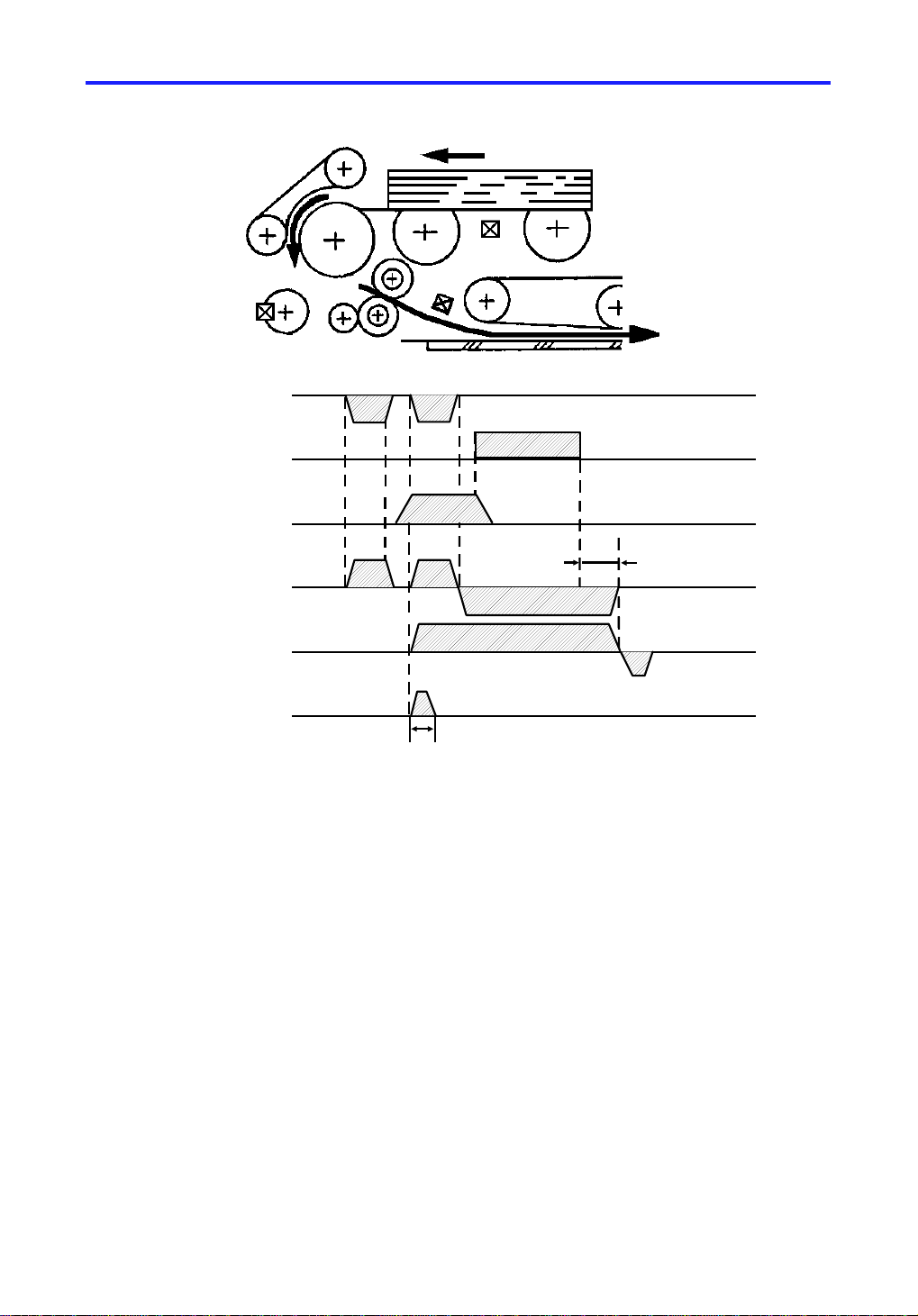
8. ORIGINAL FEED-IN
(1)
(2)
(3)
One-turn Sensor
(1)
Registration Sensor
Feed-in MC
(1)
Feed-in Motor
Transport Belt
Motor
Friction Belt
Motor
(2)
(2)
(2)
(2)
50m sec
(3)
(3)
100ms
Soon after the entire stack of the originals are move d to the fee d-in position
(1), the feed-in clutch and the friction belt moto r turn on. The frict ion belt
motor rotates for 50 milliseconds count er to the direct ion of the feed roller
rotation to ensure the separation of the bottom original (2).
When the leading edge of the original reaches the registration sensor, the
feed-in clutch turns off and the feed-in motor reverses (3). From this time
onward, the pull-out rollers ta ke ove r and feed th e orig ina l to th e transport
section.
The registration sen sor also serves to measure the original length. The RDH
CPU determines the origina l size by counting how many pulses it receives
while the original passe s t he se nso r.
The original width is checked by the origin al width sensor, which is located
next to the registration sen sor.
The original stop position is determined by pulse cou nt from the time the
original trailing edge passes the registratio n sen sor.
10
Page 12

[C]
23 April 1993 ORIGINAL INVERSION MECHANISM
9. ORIGINAL INVERSION MECHANISM
[B]
[E]
[A]
[D]
Two sided originals are inverted by the inverter rollers [A] and the inverter
pawls [B]. When the inverter sole no id [C] is energ ized, the inverter pawls are
opened and the origina l is inve rte d.
RDH
11
Page 13

ORIGINAL INVERSION MECHANISM 23 April 1993
(2)
Registration Sensor
(3)
Inverter Sensor
(1)
Inverter Sol.
239 pls
(3)
Transport Belt Motor
Inverter Motor
Friction Belt
Motor
(1)
(2)
(1)
When the Start key is pressed, the two sided original is fed into the transport
section. The inverte r so len oid is energized at the same time as th e tra nsport
belt motor and the friction belt motor turns on. (1)
When the trailing edge of th e original passes the registration sensor, the
inverter motor [D] start s turn ing . (2)
The original passes over th e exposure glass and goes into the inverter
section. Since the invert er pawls a re alre ad y open at tha t time , th e original is
inverted and directed back to the tran sport belt section. The transpo rt be lt
motor reverses 239 pulse s aft e r th e leading edge of the origina l passes the
inverter sensor [E]. (3 )
The transport belt the n moves t he origin al to the original scale.
The back side of the original is copie d firs t.
After the back side is expo sed , the transport belt motor and the inverter
solenoid turn on again. The origin al is mo ved to th e inve rter rollers and
inverted, and then moved back to the scale.
After the front side is exposed , th e orig ina l is fed out of the RDH unit.
12
Page 14

23 April 1993 ORIGINAL FEED-OUT MECHANISM
10. ORIGINAL FEED-OUT MECHANISM
[B]
[A]
[C]
When the RDH receives the feed -out signal from the copier, the transport belt
motor, the inverte r mo to r, an d th e feed-out motor [A] sta rt tu rning. Since the
inverter solenoid is off at this t ime, the invert er pa wls are po sitio ne d to direct
the original to the exit relay belts [B] . The origin al is f ed to the fe ed-out unit by
the exit relay belts and then fed out of the RDH unit.
The feed-out motor drops to half of its normal spe ed 100 milliseconds after
the original’s leading edge passe s the fee d-o ut sensor [C]. It stays at half
speed until 180 milliseconds after th e original’s trailing edge passes the
feed-out sensor. This lowe r spee d pre ven ts un eve n stacking of originals.
For B4/81/2" x 14" and larger originals, the feed-out motor changes its spe ed
280 milliseconds after the origin al’s lea din g ed ge passe s the fee d-o ut sensor.
RDH
13
Page 15

ALTERNATE PAPER FEED 23 April 1993
11. ALTERNATE PAPER FEED
An alternate paper feed system can be used when the RDH and Finisher is
installed.
This alternate paper feed system is a relat ively efficient way to make two or
more two-sided copies from two or more one -side d orig inals when the copier
is equipped with an RDH.
When making two-sided copies, first of all, the even pages of the originals
placed on the RDH are copied to the pap er from the paper tray. They are
then stored in the duplex tray. The n th e originals are recirculated, the odd
pages of the originals are copied to the shee ts sto red in the duplex tray.
When making two or more sets of copies, the even pages of the recirculated
originals are copied and they are st ore d in the duplex tray. The odd pages of
the recirculated originals are copied to the sheets stored in the duple x tray.
There are many benefits for this system.
Reduced transport time:
Before performing the two-sided copy process, the one-sided copy which has
been stored in the duplex tray is fed onto a point near the registra tio n rolle rs
simultaneously with other copy processes, by which it can saving transp ort
time.
14
Page 16

23 April 1993 ALTERNATE PAPER FEED
– Operation –
(For example)
Two sets of two-sided copies are made fro m f our one-sided originals.
1) When the start key is presse d the 4th and 2nd originals a re scan ne d,
then these copies are stacked in the duplex tray. The 3rd an d 1st
originals have only passed over the expo sure glass [Fig 1].
2) The 4th original is scanned. The copy is stacke d in the duplex tray.
Soon after this, the botto m copy in the duplex tray is fed until its leading
edge reaches the duplex exit senso r. This is in prep aration for the reverse
side copying [Fig 2].
3) The 3rd original is scanned. The cop y wh ich has bee n in th e sta nd -by
position is fed for copyin g the 3rd original and then fed out ont o th e cop y
tray [Fig 3].
4) The 2nd original is scanned and then it is stacke d in th e du ple x tray.
Soon after this, the bot to m co py in th e du plex tray is fed in preparation fo r
the reverse side copying [Fig 4].
5) The 1st original is scanned. The cop y wh ich has bee n in th e sta nd -by
position is fed for copyin g the 1st original and then fed out ont o th e cop y
tray [Fig 5].
6) The 4th original is fed in the scanner and it is fed out from the RDH
without exposing. After this, the bottom copy in th e du plex tray is fed in
preparation fo r the reverse side copying [Fig 6].
7) The 3rd original is scanned. The cop y wh ich has bee n in th e sta nd -by
position is fed for copyin g the 3rd original and then fed out ont o th e cop y
tray [Fig 6].
8) The 2nd original passes over the expo sure glass. After this, the bott om
copy in the duplex tray is fed in prep ara tion for the reverse side cop ying
[Fig 7].
9) The 1st original is scanned, the copy which has been in the stand-by
position is fed for copyin g the 1st original and then fed out ont o th e cop y
tray [Fig 7].
RDH
15
Page 17

①
②
③
❹
③ ② 4
❹❸❷
❶
①
④
4
2
ALTERNATE PAPER FEED 23 April 1993
④
①
②
③
④
2
4
4
③
4
<RDH>
1
2
3
4
2
4
<Duplex tray>
<Paper tray>
Fig 1 Fig 2 Fig 3
❸
❹
①
②
①
③
④
2
2
❷
❸
❹
①
2
4
②
④
2
❸
③
2
④
2
4
②
④
Fig 4 Fig 5 Fig 6
3
4
❶
❷
❶
②
❸
①
④
③
4
②
❍: Recirculated
●: 3rd recirculated
: Without exposing
(for RDH)
Fig 7
16
Page 18

23 April 1993 ORIGINAL MISFEED SENSING
12. ORIGINAL MISFEED SENSING
The copier CPU lights the original misfeed indicator if the pre viou s origin al
remains on the exposu re gla ss a ft er man ua l copyin g an d RDH f ee d is
attempted. When the RDH is lifte d and the previous original is removed, RDH
copying is permitted.
12.1 One-sided original
Registration
Sensor
Inverter
Sensor
Feed-out
Sensor
Feed-in
Motor
Inverter
Motor
ON Check
(750 ms)
OFF Check
(640 ms)
ON Check
(700 ms)
OFF Check
(850 ms)
ON Check
(700 ms)
OFF Check
(1250 ms)
If the registration sensor is not actu at ed wit hin 750 millise con ds af te r the
feed-in motor starts turning , the Orig ina l Misfee d indicator lights (ON check).
If the registration sensor does no t tu rn of f with in 64 0 milliseco nds, th e CPU
determines that there has been an original misfeed (O FF check).
If the inverter sensor is not act ua te d within 700 milliseconds after the inverter
motor starts turning (ON ch eck) or if th e inve rter sensor does not turn off
within 850 milliseconds, the Original Misfeed indicator turns on.
If the feed-out sensor is not actu at ed wit hin 700 millise con ds af te r the invert er
sensor turns off (ON check), or if the feed-out sensor does not turn off within
1250 milliseconds, the Original Misfeed indicat or ligh ts (OFF che ck).
17
RDH
Page 19

ORIGINAL MISFEED SENSING 23 April 1993
12.2 Two-sided original
Registration
Sensor
ON
Check
(750 ms)
OFF Check
(640 ms)
OFF
Check
(700 ms)
ON
Check
(750 ms)
OFF
Check
(700 ms)
ON
Check
(750 ms)
OFF
Check
(700 ms)
ON Check
(700 ms)
OFF Check
(1250 ms)
Inverter
Sensor
Feed-out
Sensor
Transport
Belt Motor
ON Check
(750 ms)
Inverter
Motor
The ON/OFF check timing of the registra tion sensor is the same as in the
one-sided original mode.
For original inversion, if th e inve rte r se nso r is not act ua te d with in 75 0
milliseconds after the inverter motor turns on (ON check) or if the inverter
sensor does not turn off within 700 milliseconds (OFF check), the Original
Misfeed indicator lights.
During original feed-ou t, ON/O FF ch ecks are perf orme d at both the inverter
sensor and the feed-o ut sensor at the same time as in the on e-sided original
mode.
18
Page 20

23 April 1993 INSTALLATION
13. INSTALLATION
13.1 ACCESSORY CHECK
Check the accessories in the box acco rdin g to the following list:
Description Q’ty
1. Installation Procedure.............................................................1
2. RDH Test Chart......................................................................1
3. Switch Actuator.......................................................................1
4. Hinge Stopper................... .......... .......... .................... .......... .... 2
5. Shoulder Screw (-) – M5...... .. ............ ...................... ...............2
6. Shoulder Screw (+) – M5....................... .. .. .. .... .. .. .. .. .. .. .... .. .. .. .2
7. Shoulder Screw – M4.............................................................2
8. Philips Pan Head Screw – M4 x 6....... ...................... ............ .2
9. NECR (for -17, -27 machines only)........... .. ...................... .....1
10. Envelope - NECR (for -17 machin e on ly).................... .. .........1
19
RDH
Page 21

INSTALLATION 23 April 1993
13.2 INSTALLATION PROCEDURE
[A]
[A]
[B]
[A]
[C]
CAUTION: When installing the Recirc ula ting Docum ent Handl er
(RDH), make sure that the copier is unplugged.
1. Remove the tape strips [A] and the cushion [B] clamping the belt unit.
2. Remove the sensor [C] from the copier (1 screw).
NOTE: Sensor [C] is not installed to the cop ier whe n it is packed in its
box.
Sensor [C] is an accessory of the plat en cover (option).
20
Page 22

23 April 1993 INSTALLATION
[B]
[A]
[B]
[C]
[E]
[D]
3. Install the cove r [A] with a screw supplied as an accessories of the copie r.
4. Install four stepp ed scre ws (fron t: M4, rear: M5 minus screw) [B] to hook
the RDH.
NOTE: There is one screw hole available on th e lef t side for one of the
stepped screw. However there are two screw hole availa ble on
the right where the ste pp ed screw is to be inst alle d.
Install the stepped screw into the outer scre w hole [C] as shown
in the illustration.
5. Mount the RDH to the two stepped screws [D] by align ing the hole s in the
RDH hinge [E] and the stepped screws, then slide the RDH to the right as
shown.
RDH
21
Page 23

INSTALLATION 23 April 1993
[A]
[B]
[C]
[D]
[E]
6. Secure the RDH to the copier with two plu s (M5 ) step ped screws [A ].
7. Remove a small cap on the upper rea r cover of the copie r t hen con ne ct
the connector [B] an d th e fiber optic cable connector [ C].
CAUTION: Place the fiber optic cable [C] over the electr ic al cable [B]
so as not to bend the fiber optic cable [C] while opening
and closing the RDH.
8. Install the switch actuator [D] (1 screw).
9. Close the RDH then install the two angle stoppers [E].
10. Plug in the copier and turn on the main switch.
NOTE: The copier automatically recognizes that the RDH has been
installed.
11. Make copies using the RDH a nd conf irm t he copy imag e.
22
Page 24

23 April 1993 SERVICE TABLE
14. SERVICE TABLE
14.1 TEST POINT TABLE
Number Function
TP1 GND
14.2 FUSE TABLE (Main Board)
Number Rated Current
F1 5A
14.3 LED TABLE
LED No. ON Status
LED 1 Motor speed is too high.
LED 2 Motor speed is normal
LED 3 Motor speed is low
NOTE: While each motor is adjusted, if the motor speed is normal LED 2
lights, if the motor speed is too high LED 1 lights, if the motor
speed is too low LED 3 lights.
RDH
23
Page 25

SERVICE TABLE 23 April 1993
14.4 DIP SWITCH TABLE
Factory Setting
DIP SW 2 DIP SW 1
12341234
00000000
After performing the follo wing tests, these DIP switches should be ret urn ed to
the factory settings.
Motor Test
DIP SW 2 DIP SW 1
Description Note
12341234
1000Feed-in Motor 1
1101
0100Transport Belt Motor
0010Inverter Motor
0001Feed-out Motor 2
Note 1: When these DIP SW comb ina tions are set. The motors start rotating.
While SW 3 is held down. The motor rotates in the reverse direction.
Note 2: When these DIP SW comb ina tions are set, the motors start rotating.
While SW 3 is held down, the motor rotates slowly.
Paper Feed
DIP SW 2 DIP SW 1
Description
12341234
0000
0101
0100
Feeds a sheet of paper
(Scale Registration)
Feeds a sheet of paper
(Timing Registration)
Note: With these DIP SW combination s, press SW 3 to feed a sheet of
paper. Press SW 3 again to reverse the paper fe ed direct ion , th en
press SW 3 to feed out the paper sheet.
24
Page 26

23 April 1993 SERVICE TABLE
Clutch and Solenoid Test
DIP SW 2 DIP SW 1
12341234
1000Push Plate Solenoid
0011
0100Feed-in Clutch
0010Inverter Solenoid
0001Original Gate Solenoid
Note: Press SW 3 to energize the clutches and solenoids.
Free Run Mode (With paper)
DIP SW 2 DIP SW 1
Description Note
12341234
0000Single Operation
(Scale Registration,
Single Side)
1000Single Operation
(Scale Registration,
Double Side)
1001
0100Single Operation
(Timing Registration,
Single Side)
Description
1
* * 0 1 Repeat Operation
(Up to 30 sets)
* * 1 1 Repeat Operation
(Limitless)
Note 1: With these DIP SW combination s, press SW 3 to start feeding sheets
from a paper stack in and out. Each sheet is fed once.
Note 2: With these DIP SW combination s, press SW 3 to feed paper in and
out continuously. (The same stack of shee ts is fed in and out
repeatedly.)
Free Run (Without paper)
DIP SW 2 DIP SW 1
Description
12341234
11100000Free Run
Note: With this DIP SW combination , pre ss SW 3 to start RDH o peration
without paper. Press SW 3 again to stop .
RDH
25
Page 27

[D]
REPLACEMENTS AND ADJUSTMENTS 23 April 1993
15. REPLACEMENTS AND ADJUSTMENTS
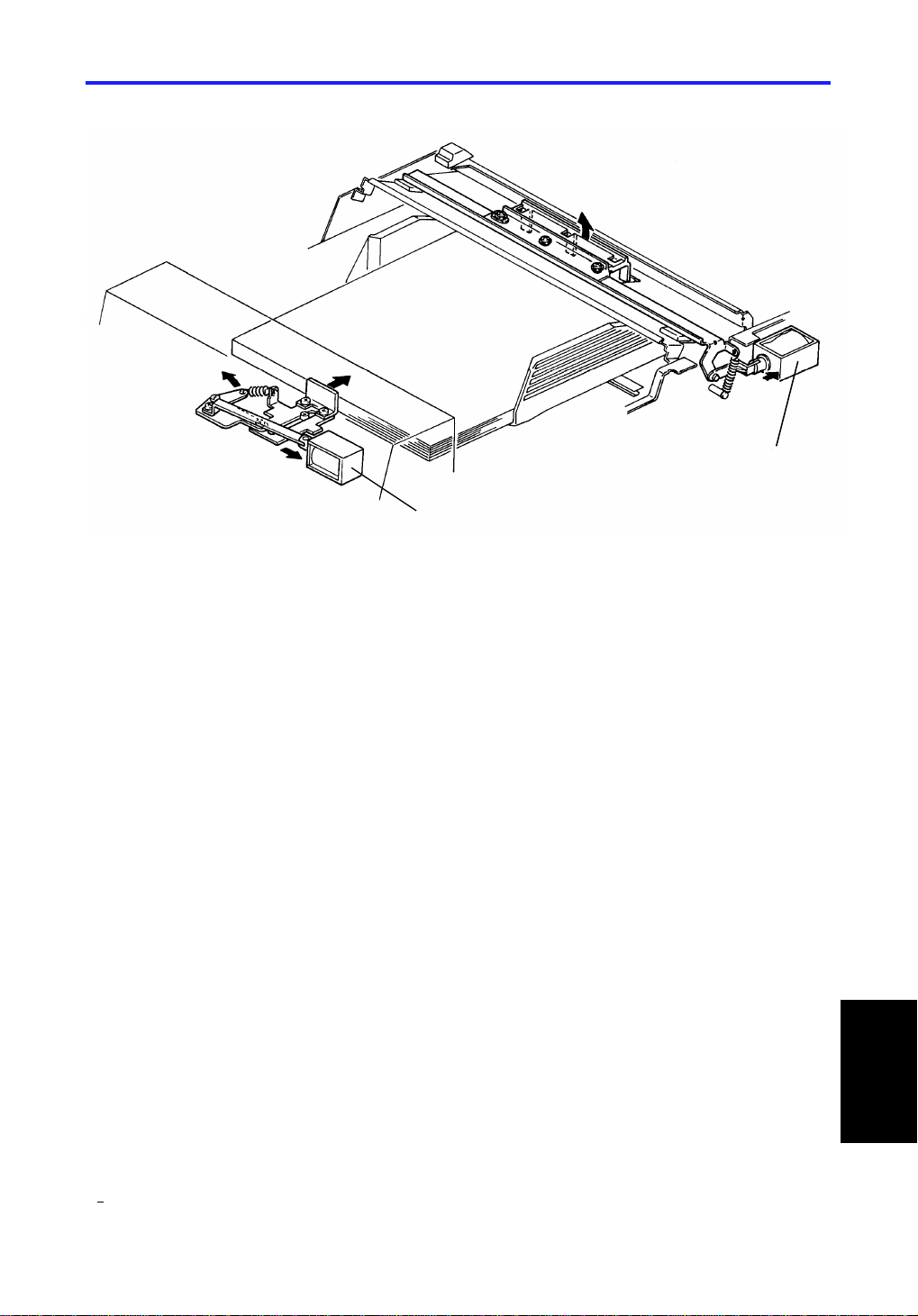
15.1 TRANSPORT BELT REPLACEMENT
[E]
[A]
[C]
[B]
1. Turn off the copier main switch and lift the RDH unit.
2. Open the transport belt unit [A] (2 screws).
3. Slide the belt tension plate [B] to the left (1 screw), then lower
the belt tension unit [C].
4. Replace the transport belt.
NOTE: The RDH belt has to be installed in the notch as shown [D] .
The feed out unit [E] has to be opened when the transport belt
unit is reinstalled.
26
Page 28

23 April 1993 REPLACEMENTS AND ADJUSTMENTS
15.2 PAPER FEED ROLLER REMOVAL
[E]
[B]
[D]
[a]
[A]
[a]
[C]
[H]
[F]
[a]
[I]
[G]
1. Turn off the cop ier main swit ch, the n remo ve the RDH front cover [A]
(remove 2 screws, loosen 3 screws [a]) and the lower rear cover [B] (2
screws).
2. Remove the rear cover [C] (4screws).
3. Open the feed-in unit [D].
4. Remove the feed-in unit cover [E ] (4 screws) an d th e pa pe r guid e mylar
[F] (2 screws).
5. Loosen the feed-in unit relea se bu tt on hold er pin s [G] , th en slide the
holder to the front and remove th e paper f eed gu ide plat e [H] (2 screws).
6. Remove the paper fe ed roller [I] (3 E-rings, 1 bearing, 2 pins, an d 2
pull-out rollers).
NOTE: Be careful not to lose the pins.
27
RDH
Page 29

[A]
REPLACEMENTS AND ADJUSTMENTS 23 April 1993
15.3 FRICTION BELT REPLACEMENT
[B]
[C]
1. Turn off the copier main switch, the n open the pape r feed unit [A] .
2. Remove the paper guide plate [B] (2 screws).
3. Replace the 3 frict ion belts [C] (1 E-ring and 1 busing).
28
Page 30

23 April 1993 REPLACEMENTS AND ADJUSTMENTS
15.4 PAPER EXIT TRANSPORT BELT REMOVAL
[C]
[A]
[B]
[D]
[E]
[H]
[G]
1. Turn off the copier main switch.
[F]
2. Remove the lower rear cover [A ], rear cover [B] and the right side cove r
[C] (2 screws).
3. Remove the inverter sole no id bra cket [D] (2 screws).
4. Slide the paper exit unit all the way to the left.
5. Remove the 2 screws for the transport unit [E] , and open the exit unit.
Then remove the other 2 screws [F].
6. Carefully lift the front en d of the tran spo rt un it [G ], then remove the 4
paper exit transport belts [H] .
NOTE: Reinstall the inverter solenoid bra cket , af ter sliding the paper exit
unit all the way to the right.
RDH
29
Page 31

REPLACEMENTS AND ADJUSTMENTS 23 April 1993
15.5 RDH MAIN CONTROL BOARD REMOVAL
[B]
[A]
[C]
[D]
1. Turn off the copier main switch, the n remo ve th e rea r cover.
2. Disconnect all connectors for the main con tro l boa rd and for the flexib le
cable (8 connectors, 1 optics cable, 1 harness clamp).
3. Remove the LED bracket [A] (1 screw) and the flexible cable [B]
(2 screws).
4. Remove the main board cover [C] (2 screws).
5. Remove the main control board [D].
NOTE: After replacing the main con trol board, perform the lea din g ed ge
registration and the motor speed adju stme nt s.
30
Page 32

23 April 1993 REPLACEMENTS AND ADJUSTMENTS
15.6 RDH LEADING EDGE REGISTRATION ADJUSTME N T
NOTE: Before confirming the original registration, make sure th at the main
frame registration is within specif icat ion s.
1. Confirm the original front side registra tion as follows:
1) Make a copy of the te st chart in platen mode (A4/81/2" x 11", sideways).
2) Make a copy of the test chart in RDH mode.
3) Compare the registratio n of the copy in pla te n mod e with that in RDH
mode, and confirm that there is no more th an a 1.0 mm dif fe ren ce.
4) If the differen ce is mo re th an 1.0 mm, adju st th e registration by using
the copier’s SP mode ( SP Adjustment – PAGE 6).
1
5) Install the RDH rear cover.
RDH
31
Page 33

REPLACEMENTS AND ADJUSTMENTS 23 April 1993
[A]
[B]
2. Confirm the original reverse side registration as follows:
1) Make a copy of the test cha rts 2n d side in platen mode (A4/81/2" x 11",
sideways).
2) Make a copy of the test chart in RDH 2-sided mod e.
3) Compare the registratio n of the copy in pla te n mod e with that in RDH
2-sided mode, and confirm that there is no more than a 2.0 mm
difference.
4) If the differen ce is mo re th an 2.0 mm, remove the left scale [A] (2
screws), then set a sheet of A4/8 1/2" x 11" sideways pa per [ B] on the
exposure glass edge as shown.
NOTE: Without the left scale, the original jams when it strikes the
exposure glass edge. This sheet of paper prevents that.
5) Set DIP SW 1 and 2 on the main PCB as follows:
DIP SW 2 DIP SW 1
12341234
01010100
32
Page 34

[C]
23 April 1993 REPLACEMENTS AND ADJUSTMENTS
[D]
10.0 ± 2..0 mm
6) Set a test chart on the RDH, then press SW 3 to feed the test chart
through the RDH.
7) When the test chart st ops o n th e exp osure glass, gently pull off th e
sheet of paper set in step 4), then press SW 3 again to feed the test
chart in the reverse direction.
8) Open the RDH slowly so that the test chart [C] does not move from the
stop position.
9) Confirm that the test chart has stop ped at the correct position, 10 ± 2.0
mm from the scale edge (0 position) [D].
10) If the test chart did not stop at the correct position, adjust the
registration by using the copier’s SP mode ( SP Adjustment –
1
PAGE 6).
3. Turn all DIP SW’s off and turn off the main switch , th en reassemble the
machine.
4. Check the operation of the RDH.
RDH
33
Page 35

REPLACEMENTS AND ADJUSTMENTS 23 April 1993
15.7 MOTOR SPEED CHECK & ADJUSTMENT
1. Remove the RDH rear cover (4 screws), and set DIP SW 1 and 2
as follows:
DIP SW
DPS 2 DPS 1
Description
DIP SW
Combination
12341234
1 0 0 0 Feed-in Motor 1
Transport Belt
Motor
1101
0100
0010 Inverter Motor 3
0 0 0 1 Feed-out Motor 4
2
34
Page 36

23 April 1993 REPLACEMENTS AND ADJUSTMENTS
[A]
2. Close the RDH and remove the LED cove r [A] (1 screw).
NOTE: For the DIP SW combinations, ref e r to the tab le on the previo us
page.
3. Set DIP SW 1 combina tio n #1 . The paper feed motor start s turning. Turn
VR 3 until LED 2 lights.
4. Set DIP SW 1 combina tio n #1 . The paper feed motor reverse s direct ion
while SW 3 is pressed (ON). Turn VR 2 until LED 2 lights.
5. Set DIP SW 1 combinatio n #2 . The tran sport belt motor starts. Turn VR 1
until LED 2 lights.
6. Set DIP SW 1 combina tio n #3 . The inverter motor starts turning. Turn VR
4 until LED 2 lights.
7. Set DIP SW 1 combina tio n #4 . The feed-out motor starts turning. Turn
VR 5 until LED 2 lights.
8. Check the operation of the RDH.
9. Turn all DIP SW’s off.
10. Reassemble the machine.
RDH
35
 Loading...