

Page 1
Technical Bulletin No. RTB-003
SUBJECT: F410 RDH Finisher system duplex method change
(manual corrections)
PREPARED BY: S. MANO
CHECKED BY:
CLASSIFICATION:
Action Required
Troubleshooting
Retrofit Information
For the F410, the alternate paper feed system is disabled.
The following is the new method the F410 uses for copying 1 sided originals to 2 sided
copies.
Please delete pages 14, 15, and 16 of the RDH section and insert the following
explanation.
Revision of service manual
Information only
Other
FROM: Copier Technical Support Group
MODEL: F410
DATE: SEP. 15. ’93
PAGE: 1 of 2
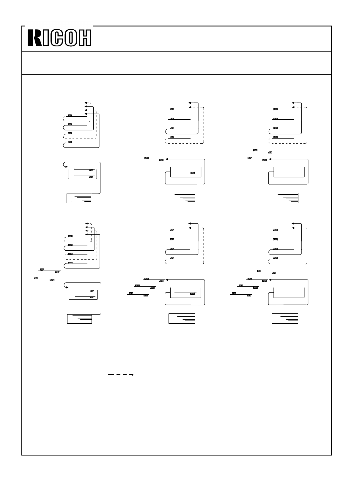
1 SIDED ORIGINAL TO 2 SIDED COPY MODE
When making two-sided copies, first of all, the even pages of the originals placed on the
RDH are copied to the paper from the paper tray. They are stored in the duplex tray. Then
the originals are recirculated, and the odd pages of the originals are copied to the sheets
stored in the duplex tray.
When making two or more sets of copies, the following copy sets are made in the same
way as the first set copy.
Therefore, the original recirculates twice for each copy set.
-Operation- (For example)
Two sets of two-sided copies are made from four one-sided originals.
1) When the start key is pressed, the 4th and 2nd originals are scanned then these
copies are stacked in the duplex tray. The 3rd and 1st originals have only
passed over the exposure glass [Fig. 1].
2) Soon after the 1st recirculation is completed, the second recirculation starts. The
4th originals just passes the exposure glass then the 3rd original is scanned.
This image is copied onto the copy which has been fed from the duplex tray and
is then fed out onto the finisher [Fig. 2].
3) The 2nd original just passes the exposure glass and then the 1st original is
scanned. The copy from the duplex tray is fed for copying the 1st original and
then fed out onto the finisher. At this moment, the duplex tray becomes empty
[Fig. 3].
4) The following steps repeat steps 1) to 3). [Fig. 4] to [Fig. 6].
Page 2
Technical Bulletin No. RTB-003
2 43’
4’3’1’
2’
②
③
SUBJECT: F410 RDH Finisher system duplex method change
(manual corrections)
<RDH>
1
2
3
4
<Duplex>
2
4
<Paper tray>
Fig 1
3’
4’
1’
2’
2’
3’
4
2
Fig 2
❶
①
❷
DATE: SEP. 15. ’93
PAGE: 2 of 2
1’
Fig 3
❸
❹
❸
④
1’
3’
2
4
②
1’
3’
④
❹
❸
④
2
4
②
1’
3’
❸
❶
❷
❶
②
④
2
4
Fig 4 Fig 5 Fig 6
1 2 3 4: 1st recirculated
1’ 2’ 3’ 4’: 2nd recirculated
① ② ③ ④: 3rd recirculated
❶ ❷ ❸ ❹: 4th recirculated
: Without exposing
(for RDH)
Page 3
Technical Bulletin No. RTB-017
SUBJECT: MANUAL CORRECTIONS DATE: Jan. 31,’94
PAGE: 9 of 13
Page 6-19 1.15
• Incorrect
1.15 DUAL JOB FEEDER
Definition: [Level:B]
Encoder pulse is not detected by the DJF main board......
Possible causes
DJF feed motor defective
DJF transport motor defective
DJF feed out motor defective
DJF inverter motor defective
• Correct
1.15 DUAL JOB FEEDER/RECIRCULATING DOCUMENT HANDLER
Definition: [Level:B]
Encoder pulse is not detected by the DJF/RDH main board......
Possible causes
DJF/RDH feed motor defective
DJF/RDH transport motor defective
DJF/RDH feed out motor defective
RDH inverter motor defective
Page 4

Page 35 of RDH step #2
Since there is no LED cover, delete the cover [A] from the illustration and correct the
following sentence.
•Incorrect
Close the RDH and remove the LED cover [A] (1 screw).
•Correct
Close the RDH.
[A]
Page 5

Technical Bulletin No. RTB-019
SUBJECT: RDH Original Size Misdetection DATE:
February. 15,1994
PAGE: 1 of 10
PREPARED BY: S. MANO
CHECKED BY:
CLASSIFICATION:
Action Required
Troubleshooting
Retrofit Information
When the RDH detects different original sizes on successive jobs, the RDH stops the
operation and indicates an original jam.
REASON OF THE MISDETECTION
Revision of service manual
Information only
Other
[B]
FROM: Copier Technical Support Section
MODEL:
RDH for F410
[C]
[A]
Original length is detected by the pulse generator sensor [A]. the RDH counts pulses from
the point where the leading edge of the original activates the registration sensor [B] until
the trailing edge of the original de-activates the registration sensor. The pulse count is
compared with the reference data which is stored in the ROM to judge the original size.
The pulse generator wheel is driven by the driven pull-out roller [C].
From October to November 1993 production, grease was applied to the four driven roller
shaft holders. When this grease on the shaft holders is contaminated with paper dust, it
increases the mechanical load to the driven pull- out roller shaft resulting in the slippage
between this roller and the original.
Due to the slippage, the pulse count varies. Because of this pulse variation, it is possible
that the RDH detect the original length incorrectly.
Page 6

Technical Bulletin No. RTB-019
SUBJECT: RDH Original Size Misdetection DATE:
February. 15,1994
PAGE: 2 of 10
COUNTERMEASURES
• Software modification-1
To improve the original length size detection accuracy, the pulse number reference data
has been corrected. (ROM part number from A3785810C to A3785810D).
• Software modification-2
UK (8" x 10") size lengthwise and GT (8" x 10 1/2") size lengthwise paper are very similar
and it is very difficult to distinguish them by the pulse number.
Therefore, the software has been changed to detect as only UK size lengthwise when
either of sizes is fed. (By changing the DIP switch combination, RDH can be set to detect
GT lengthwise).
Since the mixed size original detection is not necessary for the RDH, this function was
eliminated. RDH detects only the first original size for auto paper size selection, (ROM part
number from A3785810D to A3785810F).
NOTE: The part number A3785810E does not exist.
• Mechanical modification (Driven pull-out roller holders)
To reduce the pulse count variation, four holders of driven pull out roller have been
modified. To reduce the friction between the roller shaft and the holders, the inner
diameter of the holders has been widened.
• Production procedure change
The grease is not applied.
Page 7

Technical Bulletin No. RTB-019
SUBJECT: RDH Original Size Misdetection DATE:
February. 15,1994
PAGE: 3 of 10
FIELD MACHINE COUNTERMEASURE
Change the ROM on the RDH main board from A3785810C or A3785810D to A3785810F.
Clean the driven pull-out roller shaft with alcohol.
Replace the four driven pull-out roller holders.
Refer to the countermeasure procedure on the following pages.
The modification has been implemented on mass-production machines from the following
serial number:
A378-10 5393120001∼
A378-15 4143120001∼
A378-17 From the first production machine
A378-22 5343120001∼
A378-26 3E01230001∼
A378-27 A3403120109∼
Page 8

Technical Bulletin No. RTB-019
SUBJECT: RDH Original Size Misdetection DATE:
February 15, 1994
PAGE: 4 of 10
REPLACEMENT PROCEDURE
[A]
[a]
[B]
[b]
[a]
[C]
[b]
[D]
[b]
[F]
1. Remove the cover [A] (2 screws).
2. Remove the rear cover [B]. (Remove 2 screws, loosen 2 screws [a].)
3. Open the f eed guide [C ].
4. Remove the front cover [D]. (Remove 2 screws, loosen 3 screws [b].)
5. Slide the exit unit [E] fully to the left.
6. Remove the bracket [F] (2 screws).
[E]
[G]
7. Replace the ROM [G].
NOTE: Be sure the ROM is set in correct direction. Confirm whether all ROM legs are
set in the socket correctly.
8. Turn on the DIP SW 1-1. (Other DIP SWs should be still off)
NOTE: If in this condition either UK (8" x 10") lengthwise or GT (8" x 101/2")
lengthwise size originals are set, RDH recognizes them as UK lengthwise size.
If DIP SW 1-1 is still off, the RDH recognizes them as GT lengthwise size.
9. Install the bracket [F].
Page 9

Technical Bulletin No. RTB-019
[G]
SUBJECT: RDH Original Size Misdetection DATE:
February 15, 1994
PAGE: 5 of 10
[C]
[B]
[D]
[A]
[E]
[F]
[G]
10. Remove the encoder assembly [A] (1 stepped screw).
11. Remove the bushing [B].
12. Remove the gear [C].
13. Remove the two screws [D] fixing the wire clamps.
NOTE: Do not pull the harness too strongly, otherwise the sensor [E] will be pulled out.
14. Move the main motor bracket [F] up and hold it (5 screws).
NOTE: This step is necessary to access the screw [G] behind this motor.
15. Remove 2 screws [G].
Page 10

Technical Bulletin No. RTB-019
[A]
SUBJECT: RDH Original Size Misdetection DATE:
February 15, 1994
PAGE: 6 of 10
[D]
16. Remove 2 screws [A].
[F]
[C]
[B]
[F]
[D]
[E]
[G]
17. Remove the pull out roller stay [B].
18. Remove the registration sensor bracket [C] (2 screws [D]).
19. Remove the original feed out stay [E] (2 screws [F]).
20. Remove the pull out roller [G].
Page 11

Technical Bulletin No. RTB-019
[C]
SUBJECT: RDH Original Size Misdetection DATE:
February 15, 1994
PAGE: 7 of 10
[A]
[C]
[D]
21. Completely wipe off the grease on the pull out roller shaft [A] with alcohol.
22. Remove inner springs (Silver) [B] and outer springs (Black) [C].
23. Replace 4 arms [D] (1 screw each).
24. Install inner springs (Silver) [B] and outer springs (Black) [C].
NOTE: Inner springs and outer springs are different, do not mix them.
[B]
[B]
Page 12

Technical Bulletin No. RTB-019
[D]
[C]
[H]
SUBJECT: RDH Original Size Misdetection DATE:
February 15, 1994
PAGE: 8 of 10
[B]
[E]
[E]
[E]
[A]
[G]
[I]
[F]
25. Assemble the original guide plate [A], the pull out roller [B], the original feed-out stay [C],
and the registration sensor bracket [D] as shown (4 screws [E])
26. Install the pull out roller stay [F] (4 screws).
NOTE: Before fixing the 4 screws, close the feed guide [G] so that the pull out roller
arms [H] locate above the projections [I] on the feed guide.
Page 13

Technical Bulletin No. RTB-019
SUBJECT: RDH Original Size Misdetection DATE:
February 15, 1994
PAGE: 9 of 10
[A]
This should be a
short gold
colored screw
[B]
[D]
[C]
OK
[E]
27. Install the main motor bracket [A] (5 screws).
28. Fix the wire cramps [B] (2 screws).
29. Install the gear [C].
30. Install the bushing [D].
31. Install the encoder assembly [E] (1 stepped screw).
NOTE: 1. Make sure that the stepped screw [F] is correctly tightened as shown.
2. Make sure that the sensor [G] is set on the bracket properly.
[G]
[F]
NO
Good
Page 14

Technical Bulletin No. RTB-019
SUBJECT: RDH Original Size Misdetection DATE:
February 15, 1994
PAGE: 10 of 10
[C]
[B]
[A]
32. Install the front cover [A] (5 screws).
33. Install the rear cover [B] (4 screws).
34. Install the cover [C] (2 screws).
Page 15

Technical Bulletin No. RTB-042
SUBJECT: USER REMARKS WHILE SETTING THE ORIGINAL ON
THE RDH
PREPARED BY: S. MANO
CHECKED BY: S. Hamano
CLASSIFICATION:
Action Required
Troubleshooting
Retrofit Information
During field survey, we found cases that an incorrect feed out unit position created original
jams.
Please instruct the customer to set the feed out unit in the correct position.
Especially for machines which are used by many casual customers, it will be helpful for
reducing the original jams by putting a copy of the page 2 of this RTB on the wall behind
the RDH.
Revision of service manual
Information only
Other
FROM: 2nd Technical Support Section
MODEL: RDH for
DATE: JULY 31 ’94
PAGE: 1 of 2
F410/F420
Page 16

Technical Bulletin No. RTB-042
SUBJECT: USER REMARKS WHILE SETTING THE ORIGINAL ON
THE RDH
DATE: JULY 31 ’94
PAGE: 2 of 2
To prevent original jams,
slide the feed-out unit [A] to match the size marks on
the front of the recirculating document handler (RDH).
[A]
Page 17

Technical Bulletin No. RTB- 046
SUBJECT: SOFTWARE MODIFICATION DATE: Dec. 31, ’94
PAGE: 3 of 7
2. "B" version ROMs
From the following serial numbers, the EPROMs (A0965151A and A0965153A) on the
main board have been updated to version "B".
NOTE: We will re-issue this RTB as soon as the cut-in serial number becomes
available.
Code Serial Number
A095-10 5204
A095-15 264
A095-17 A3354
A095-22 5234
A095-26 3D5
A095-27 A3354
A095-29 A3354
A096-10 5244
A096-15 284
A096-17 A3364
A096-22 5274
A096-26 3D6
A096-27 A3364
A096-29 A3364
A097-10
A097-15
A097-17
A097-22
A097-26
A097-27
A097-29
Caution: Whenever replacing from the old main ROMs to the new version ROMs in
the field, this modification is necessary.
The following are corrected by this software change:
2-1. Machine enters the screen saver mode during auto counting
If the time to enter the screen saver mode (this time can be changed by using User tools)
comes during the auto count mode, the machine enters the screen saver mode. After
counting all originals, the machine indicates the original jam condition.
Page 18

Technical Bulletin No. RTB- 046
SUBJECT:SOFTWARE MODIFICATION DATE: Dec. 31, ’94
PAGE: 4 of 7
2-2. Operating time indication is incorrect
During operation, the time remaining before the end of the copy job is indicated by
animation on the touch panel screen.
During the duplex mode by using RDH and Finisher, the indicated time was incorrect.
<Countermeasure>
For the single side original to duplex copy mode, it is impossible to calculate the time due
to a highly complex operation using the alternate feed system. Therefore, in this mode,
the operating time is not indicated.
For the duplex original to duplex copy mode, the accuracy of the indicated operation time
has been improved.
2-3. RDH and Finisher, copy set limitation (maximum: 50 sets)
When using the RDH and Finisher, the selectable copy set for sort mode should be "999"
(In the sort mode, due to the alternate feed operation, the paper stocked in the duplex tray
is always less than 50 sheets). However, it was limited to 50. If a larger number was
entered, it was canceled and "50" was displayed.
2-4. RDH and Finisher, Copier misfeed caused by the original misfeed
When an original exit jam occurs in the RDH, it should not cause a copier misfeed (the
copier should exit all sheets in the copier then stop) but actually a misfeed also occurs in
the copier. This symptom occurs depending on the copy tray selected and the size of the
copy paper. (The combination of the longer paper path and shorter paper length tends to
create this symptom.)
Page 19

REVISED ON: APRIL 15, ’96
Technical Bulletin No. RTB-051
SUBJECT: RDH Original Auto Count Disabled
(North America versions only)
PREPARED BY: M. Mimura
CHECKED BY:
CLASSIFICATION:
Action Required
Troubleshooting
Retrofit Information
<Symptom>
When making one sided to two sided duplex copies with Energy Star compliant
machines, the RDH will not count the number of originals (faulty Even original mode).
<Cause>
Software error
<Field Solution>
1. Turn on the copier main switch with the RDH installed.
Revision of service manual
Information only
Other
FROM: 1st Field Information Dept. QAC
MODEL:
DATE: February
29, ’95
PAGE: 1 of 2
F410 / 420
2. Press the One Side → Two Sided duplexing key. (This key is the default selection
key on Energy Star machines. However, it must be pressed again for this
operation.)
3. Press the User Program key.
4. Store the current mode in the program #5.
5. Turn the machine off and on.
6. Confirm that the RDH counts the number of originals. (Confirmation also can be
done by pressing the Check Modes key. If "Even" is not displayed on the
Duplex/Series Copies tag, the correction has been successful.)
NOTE: 1. If the default mode is changed to single-side copying or two-sided to
two- sided duplexing, selecting the one-sided to two-sided mode will not
cause the problem.
2. The above procedure is to be done one time only per machine.
The corrected data will be kept on the RAM board.
Page 20

REVISED ON: APRIL 15, ’96
Technical Bulletin No. RTB-051
SUBJECT: RDH Original Auto Count Disabled
(North America versions only)
<Affected Machines>
Energy Star compliant machines configured with the RDH. See MB # 114 for cut-in
serial number information of the Energy Star modification.
<Factory Action>
The program has been corrected to reflect the solution. The part numbers of the
new ROM are as follows:
A0965155 B
A0965157 B
The new ROMs have been implemented to the production machines from the
following serial numbers:
Model Code Cut-in Serial No.
F400 A095-10
A095-15
A095-17
F410 A096-10
A096-15
A096-17
F420 A097-10
A097-15
A097-17
52064300 02
26643002 28
A3356430 280
524604XX XX
28644000 01
A3366430 322
528604XX XX
29644000 01
A3376440 001
DATE: February
29, ’95
PAGE: 2 of 2
 Loading...