

Page 1

DOCUMENT FEEDER
(Machine Code: B444)
Page 2
24 July, 2001 MECHANICAL COMPONENT LAYOUT
1. OVERALL INFORMATION
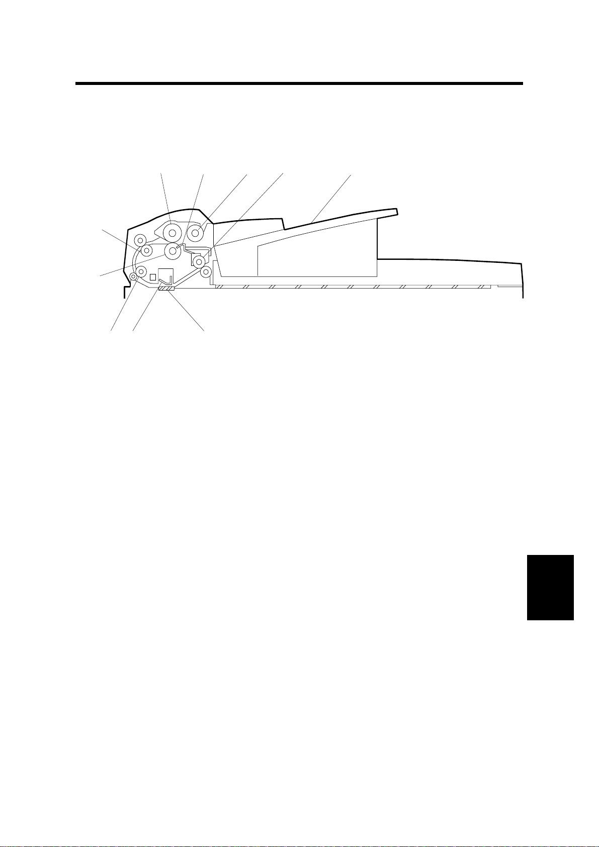
1.1 MECHANICAL COMPONENT LAYOUT
1
10
9
8
1. Feed roller
2. Original set sensor
3. Pickup roller
4. Original exit roller
5. Original table
2
3
4
5
B444V102.WMF
67
6. DF exposure glass
7. White plate
8. 2nd transport roller
9. Separation roller
10. 1st transport roller
B444-1
Peripherals
Page 3
ELECTRICAL COMPONENT LAYOUT 24 July, 2001
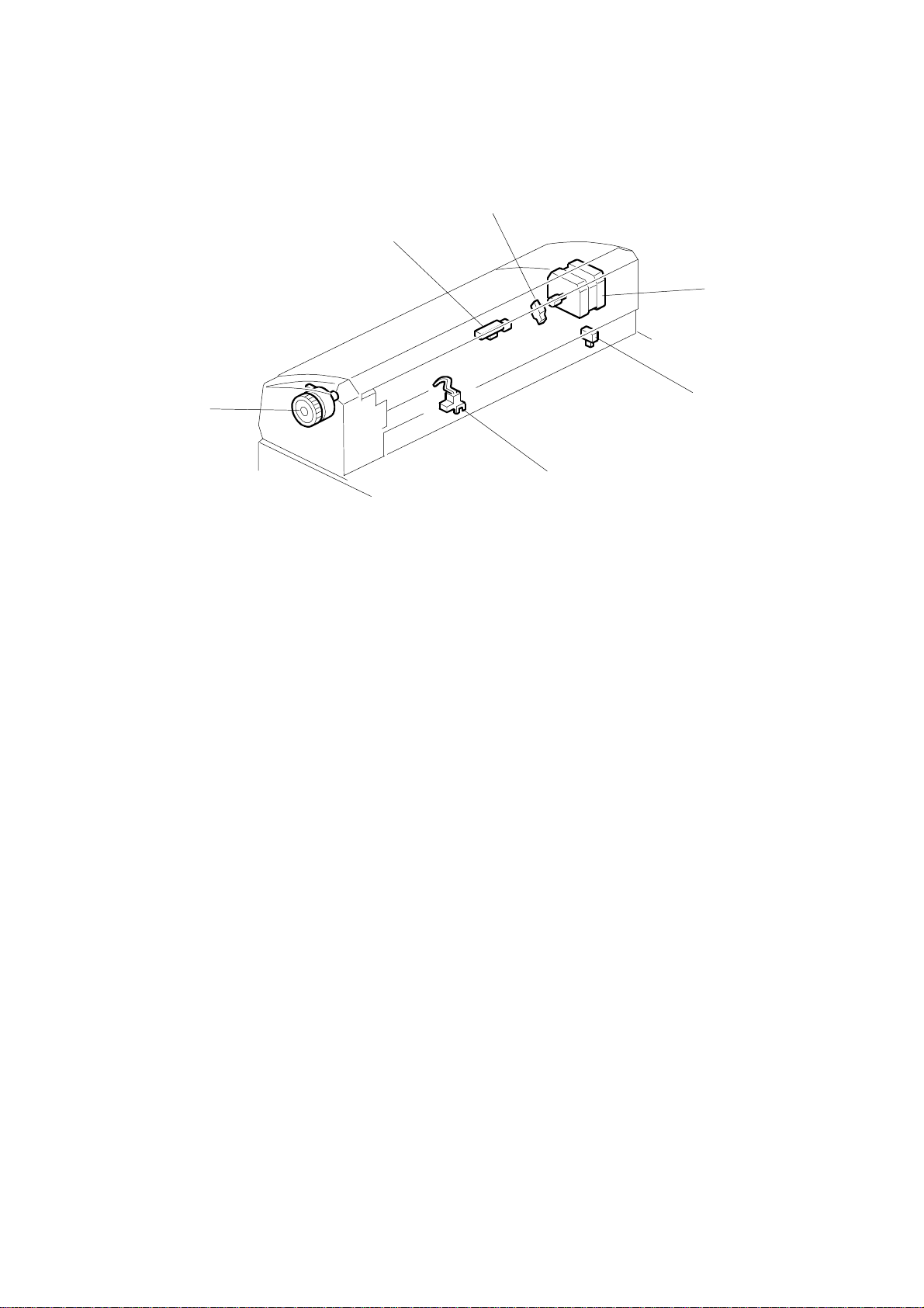
1.2 ELECTRICAL COMPONENT LAYOUT
3
2
4
5
1
6
B444V101.WMF
1. DF feed clutch
2. Original registration sensor
3. Guide open sensor
4. DF motor
5. Unit open switch
6. Original set sensor
B444-2
Page 4
24 July, 2001 DRIVE LAYOUT
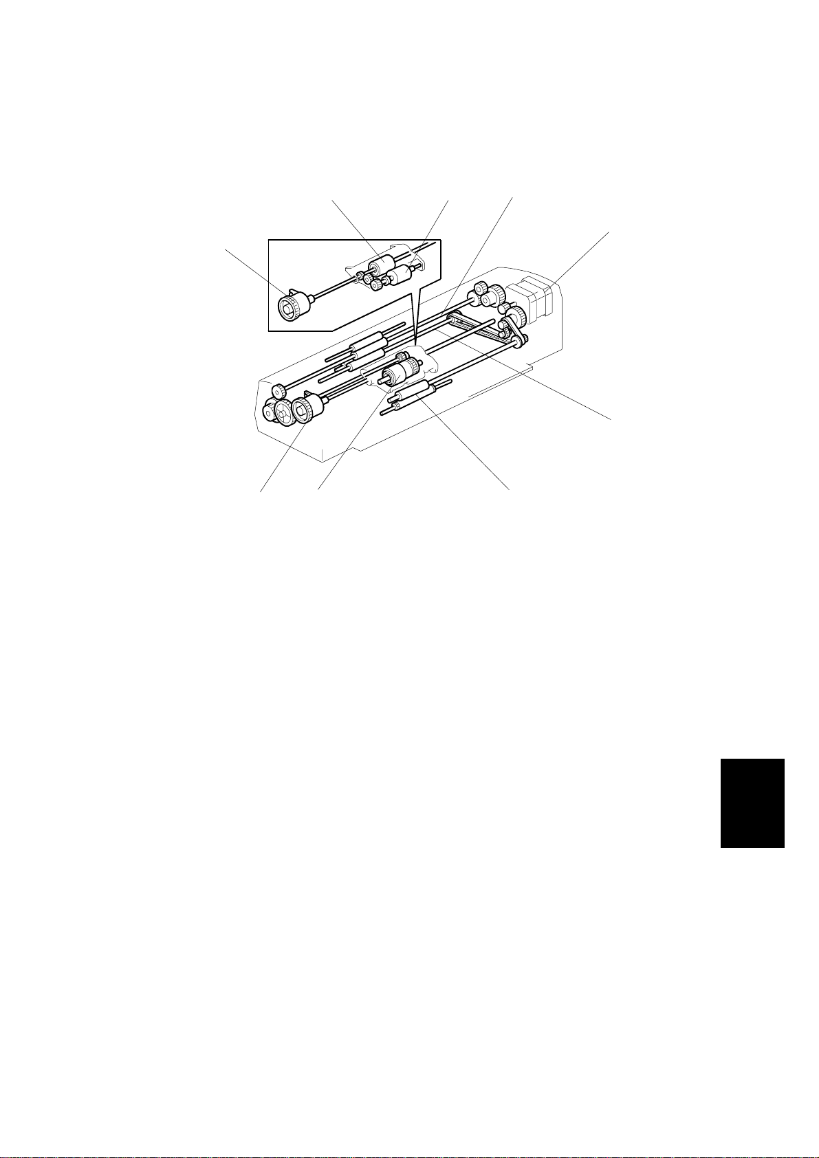
1.3 DRIVE LAYOUT
6
6
1. 1st transport roller
2. DF motor
3. 2nd transport roller
4. Exit roller
7 8
B444V104.WMF
5
1
2
3
4
5. DF separation roller
6. DF feed clutch
7. DF feed roller
8. DF pickup roller
B444-3
Peripherals
Page 5

PICK-UP AND SEPARATION 24 July, 2001
2. DETAILED SECTION DESCRIPTIONS
2.1 PICK-UP AND SEPARATION
[A]
[C]
The ADF uses an FRR (feed & reverse roller) system.
Setting paper lowers the feeler [A], causing the original set sensor [B] to inform the
CPU that the ADF is ready to feed.
Press ! → short time lag → DF feed clutch engages → DF motor starts.
The motor drives the DF pickup roller, DF feed roller, DF separation roller, and
transport rollers. The pickup roller drives the top sheet(s) between the feed and
separation roller, where the top sheet is separated and fed to the transport rollers.
[B]
B444V102.WMF
2.2 CLUTCH OPERATION
The DF feed clutch is provided to stop feeding in the event of a jam. During jamfree operation the clutch remains activated for the entire feed cycle. In the event of
a jam the clutch disengages (by torque limiter).
2.3 TRANSPORT AND EXIT
During pickup and feeding of the first sheet, the scanner moves to carry out white
adjustment and then scanning correction.
A short time after the sheet reaches the original registration sensor [C], the DF
motor stops briefly, the scanner moves to DF scan position, and the white peak is
read. The DF motor then restarts and the sheet is scanned. The exit roller ejects
the sheet.
Features of the transport mechanism:
• White peak is read for each sheet. If timing allows, the DF motor continues
running while the peak is read between consecutive trailing and leading edges.
If timing does not allow, the DF motor stops and then restarts.
• Shading correction is repeated every 10 sheets. The DF motor must stop and
restart to carry out this correction.
• Following feeding of the last sheet, the DF motor reverses briefly, raising the
pickup roller.
B444-4
Page 6

24 July, 2001 UNIT OPEN SWITCH AND GUIDE OPEN SENSOR
2.4 UNIT OPEN SWITCH AND GUIDE OPEN SENSOR
The guide open sensor is ON while the DF guide is open, and the unit open switch
is ON when the DF unit itself is raised. The machine will not carry out scanning
when either of these is ON, but will instead display a message instructing the user
to close the DF.
2.5 OVERALL ELECTRICAL CIRCUIT
FCU
Excitation
Sync/Async
Microstep Switch
CN9
Driver Current
Switch
CN10
DF Connection Board
4052
UMG8N
Low Pass Filter
SLA7033M
Motor
Driver
2SD1781
Transistor
CN104
CN105
CN106
DF Motor
Original Set
Sensor
Original
Registration
Sensor
Guide Open
Sensor
DF Feed
Clutch
Peripherals
B444-5
CN107
DF Unit
Open Switch
B444D103.WMF
Page 7

DF UPPER COVERS 24 July, 2001
3. REPLACEMENT AND AD JUSTMENT
3.1 DF UPPER COVERS
1. Open the upper guide [A].
2. DF front upper cover [B] and/or DF rear
upper cover [C] (1 screw each)
[B]
3.2 ORIGINAL TABLE
1. Push the original table [A] to the left
so that the three latches come free
of the platen cover [B], and lift off.
NOTE: When reinstalling, first set
the table flat onto the platen
cover so that the latches go
all the way in to the
openings, and be sure that
the contact area around
each latch is flush against
the cover. Then push so
that latch [1] locks into
place, then latch [2], and
then latch [3].
[1]
[3]
[C]
[A]
B444R101.WMF
[A]
[2]
[B]
B444R103.WMF
3.3 FEED UNIT
1. Raise the upper guide [A].
2. Feed unit [B] (! x 1).
[A]
[B]
B444R105.WMF
B444-6
Page 8

24 July, 2001 DF PICKUP ROLLER
3.4 DF PICKUP ROLLER
1. Feed unit (☛ 3.3)
2. Remove E-ring [A].
3. DF pickup roller [B].
[A]
3.5 DF FEED ROLLER
1. Feed unit (☛ 3.3)
2. Remove E-ring [A].
3. Lift catch [B] and pull shaft in indicated
direction.
4. DF feed roller [C]
[B]
B444R107.WMF
[C]
[B]
[A]
B444-7
B444R108.WMF
Peripherals
Page 9

DF SEPARATION ROLLER 24 July, 2001
3.6 DF SEPARATION ROLLER
1. Feed unit (☛ 3.3)
2. Open the center lid [A]
3. Lift out the separation roller ass'y [B].
4. DF separation roller [C]
[A]
[C]
B444R113.WMF
[B]
B444R110.WMF
B444-8
Page 10

24 July, 2001 DF MOTOR
3.7 DF MOTOR
1. Copier rear cover (☛ Copier Service
Manual, Section 3.3.2)
2. DF rear upper cover (☛ 3.1)
[B]
3. Unscrew and lift away the rear lower
cover [A] (" × 2).
NOTE: It is not necessary to
disconnect all connectors and
remove the cover completely.
When replacing, remember tha t
the left screw [B] must also go
through the ground line [C].
4. Motor bracket [D] (2 screws at [E]).
NOTE: Before removing the bracket,
open the three clamps (not
shown) on the bracket and
take the wiring out of the
them.
5. Motor [F] (2 screws at [G], # × 1).
[C]
B444R114.WMF
[D]
[A]
[E]
NOTE: When reinstalling, be sure that the
belt [H] is arranged as shown in the
illustration.
[H]
[G]
B444R106.WMF
[F]
Peripherals
B444R115.WMF
B444-9
Page 11

DF FEED CLUTCH 24 July, 2001
3.8 DF FEED CLUTCH
1. DF front upper cover (☛ 3.1)
2. Metal retainer [A](" × 2)
3. DF feed clutch [B] (# × 1)
3.9 SENSORS
[A]
[C]
[B]
[A]
B444R104.WMF
B444R109.WMF
1. Feed unit (☛ 3.3)
2. Three lids [A] (" × 2)
[B]: Original set sensor (# × 1)
[C]: Original registration sensor (# × 1)
[D]: Guide open sensor (# × 1)
B444R111.WMF
[B]
[D]
B444R112.WMF
B444-10
Page 12

24 July, 2001 DF EXPOSURE GLASS
3.10 DF EXPOSURE GLASS
1. Press the DF latch and raise the DF
body.
2. Original exit guide [A] (" × 3)
3. DF exposure glass [B]
NOTE: When reinstalling, set the
glass so that its padded side is
facing up.
3.11 DF CONNECTION BOARD
1. Copier rear cover (☛ Copier Service
Manual, Section 3.3.2)
2. DF connection board [A] (" × 5, all
connectors)
[B]
[A]
B444R116.WMF
[A]
B444R117.WMF
Peripherals
B444-11
 Loading...