

Page 1

DOCUMENT FEEDER
(Machine Code: B387)
Page 2
20 February, 2001 MECHANICAL COMPONENT LAYOUT
1. OVERALL INFORMATION
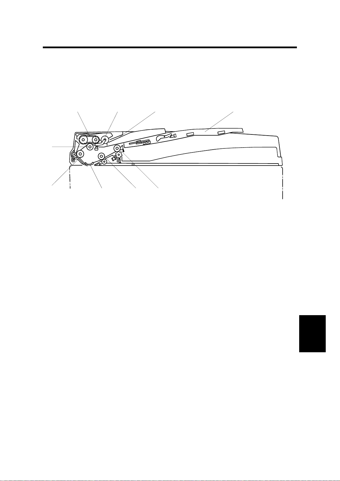
1.1 MECHANICAL COMPONENT LAYOUT
2
1
9
1. Separation roller
2. Original feed belt
3. Pick-up roller
4. Original entrance guide
5. Original table
3 4 5
678
B387V103.WMF
6. Original exit roller
7. 2nd transport roller
8. Original exposure guide
9. 1st transport roller
B387-1
Peripherals
Page 3
ELECTRICAL COMPONENT LAYOUT 20 February, 2001
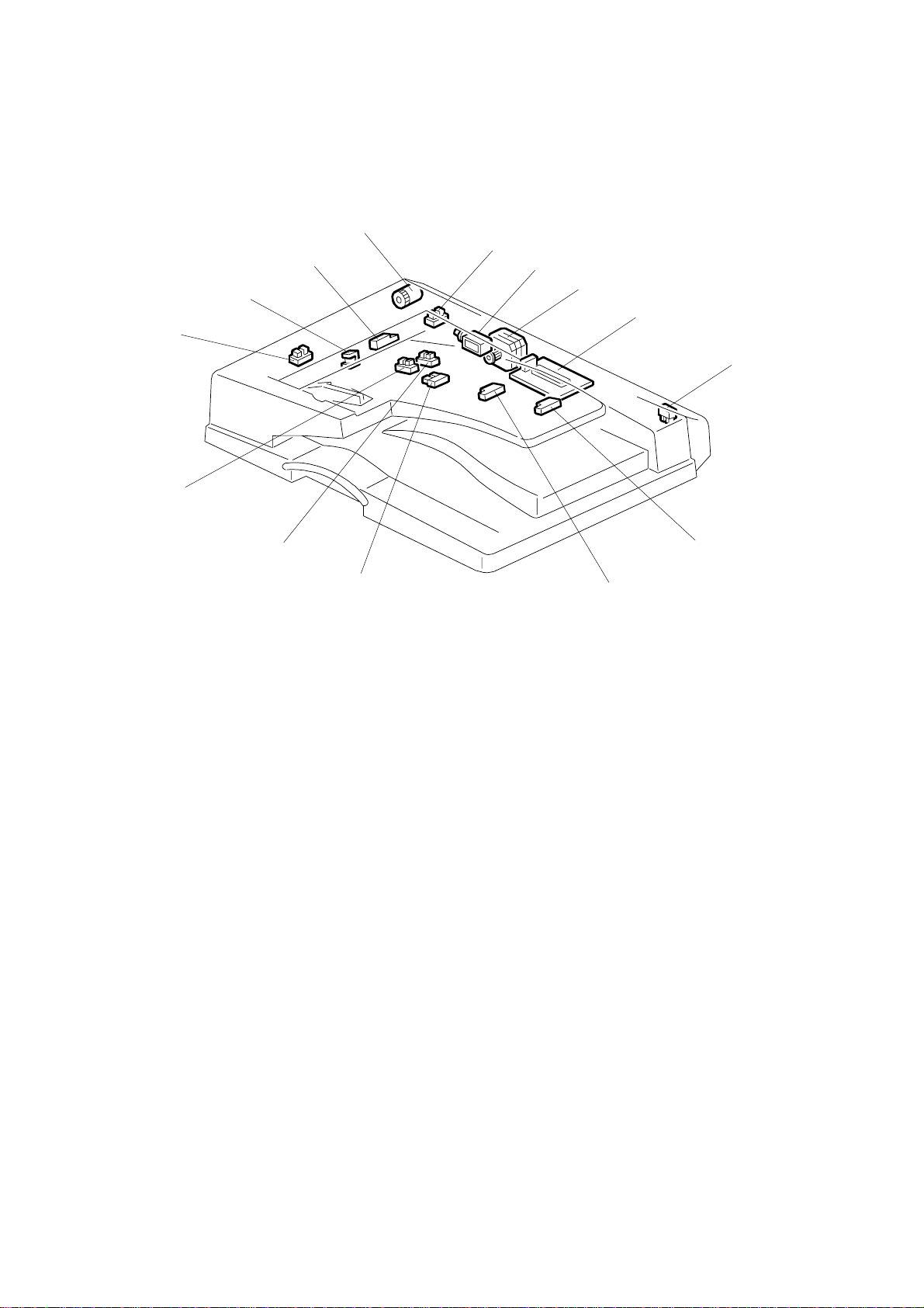
1.2 ELECTRICAL COMPONENT LAYOUT
1
2
14
13
12
11
3
4
5
6
10
9
1. DF feed clutch
2. Feed cover open sensor
3. DF pick-up solenoid
4. DF transport motor
5. DF drive board
6. DF position sensor
7. Original length sensor 2
7
8
B387V101.WMF
8. Original length sensor 1
9. Original trailing edge sensor
10. Original width sensor 1
11. Original width sensor 2
12. Original set sensor
13. Stamp solenoid
14. Registration sensor
B387-2
Page 4
20 February, 2001 DRIVE LAYOUT
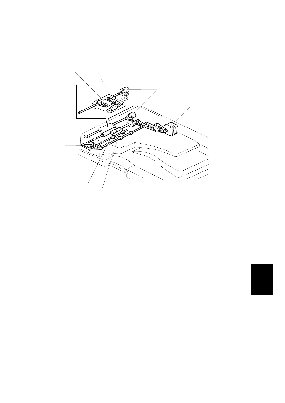
1.3 DRIVE LAYOUT
87
1
2
6
5
4
1. DF feed clutch
2. DF transport motor
3. 2nd transport roller
4. Exit roller
B387V102.WMF
5. Separation roller
6. 1st transport roller
7. Original feed belt
8. Pick-up roller
Peripherals
B387-3
Page 5
ORIGINAL SIZE DETECTION 20 February, 2001
2. DETAILED SECTION DESCRIPTIONS
2.1 ORIGINAL SIZE DETECTION
[B]
[C]
[A]
[E]
The DF uses two width sensors (width sensor 1 [A] and width sensor 2 [B]) to
detect the original width, and two length sensors (length sensor 1 [C] and length
sensor 2 [D]) to detect the original length. The DF detects the original size based
on the combination of inputs from these sensors, as indicated in the table on the
next page.
If using a non-standard original size, the user must input the original length at the
operation panel.
The original width sensors have four possible output states: P1 to P4. The output
depends on the position of the ridges on the toothed plate attached to the original
rear fence.
During one-to-one copying, copy paper is fed to the registration roller in advance to
increase the copy speed. The original exit trailing edge se nsor [E] monitors the
stack of originals in the feeder, and detects when the trailing edge of the last page
has been fed in. This stops the ADF from causing the feed of an unwanted extra
sheet of copy paper.
[D]
B387V101.WMF
B387-4
Page 6
20 February, 2001 ORIGINAL SIZE DETECTION
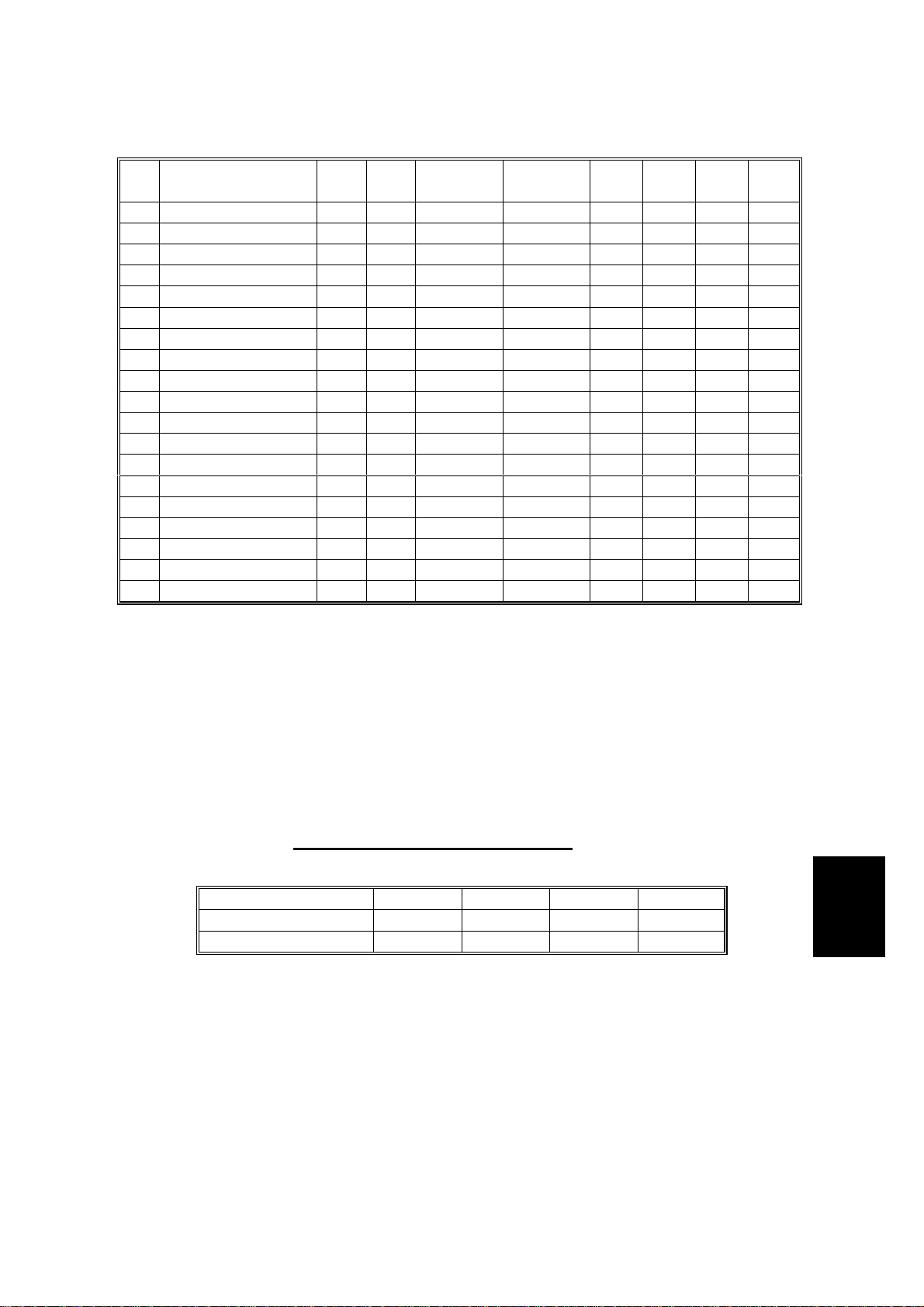
1 A3 (297 x 420)
2 B4 (257 x 364)
3 A4 SEF (210 x 297)
4 A4 LEF (297 x 210)
5 B5 SEF (182 x 257)
6 B5 LEF (257 x 182)
7 A5 SEF (148 x 210)
8 A5 LEF (210 x 148)
9 11" x 17"
10 11" x 15"
11 10" x 14"
1/2
12 8
13 8
1/2
" x 14"
" x 13"
14 8" x 13"
1/2
15 8
16 11" x 8
" x 11" SEF
1/2
" LEF
17 8" x 10" SEF
18 5
19 8
1/2
1/2
" x 8
" x 5
1/2
1/2
" SEF
" LEF
NA EU
✗❍
✗❍
✗❍
✗❍
✗❍
✗❍
✗❍
✗❍
1 ✗
❍
1
#
✗
❍✗
❍
2 ✗
✗❍
2
#
3 ✗
❍
#
4
4
❍✗
3
#
✗
❍✗
❍✗
Original
Length 1
Original
Length 2
P1 P2 P3 P4
ON ON - - - ON
ON ON - - ON ON - - ON - -
-----ON
ON - ON - - -
----ON-
--ON---
---ON-ON ON - - - ON
ON ON - - - ON
ON ON - - ON ON ON - ON - ON ON - ON - ON ON - ON - ON - - ON - -
-----ON
ON - - ON - -
--ON---
---ON--
NA: America (North, Middle, South) EU: Europe, Asia, China, Taiwan
✗: No ❍: Yes ON: Paper present
❍1, #1: In NA, original size 11" x 15" is detected as 11" x 17"
❍2, #2: In NA, original size 8" x 13" is detected as 8
❍3, #3: In NA, original size 8" x 10" is detected as 8
❍4, #4: In EU, original size 8" x 13" is detected as 8
1/2
1/2
1/2
" x 14"
" x 11"
" x 13"
- Original Width Sensor States -
Width Sensor 1 High Low Low High
Width Sensor 2 High High Low Low
Detection State P1 P2 P3 P4
Low = Blocked High = Open
Peripherals
B387-5
Page 7
PICK-UP AND SEPARATION 20 February, 2001
2.2 PICK-UP AND SEPARATION
[D]
[E]
[F]
[C]
[A]
B387D102.WMF
[B]
[H]
[G]
[I]
B387D106.WMF
An FRR (feed and reverse roller) system is used.
Setting original(s) onto the feed table lifts the original set sensor feeler [A], causing
the original set sensor [B] to issue a signal informing the main CPU that the DF is
ready to start feeding.
When the Start key (!) is pressed, the DF pick-up solenoid [C] turns on, causing
the transport guide [D] and pick-up roller [E] to lo wer onto the original, while at the
same time causing the original stoppers [F] to drop down to clear the feed path for
the original. After 200 ms, the DF transport motor [G] turns on, feeding the top
original page to the paper feed belt [H], where it is separated by the separation
roller [I].
B387-6
Page 8

20 February, 2001 ORIGINAL TRANSPORT AND EXIT MECHANISM
2.3 ORIGINAL TRANSPORT AND EXIT MECHANISM
[D]
[A]
[B]
[C]
B387V104.WMF
When the leading edge of the original reaches the registration sensor at [A], the DF
transport motor turns off. After a short time the DF transport motor turns on again.
The original is fed past the DF exposure glass [B], where it is scanned. It is then
fed through to the 2nd transport roller [C] and fed out by the exit roller [D].
The DF transport motor uses a constant speed to feed the original up to the
registration sensor. When the motor turns on again to feed the original to the DF
exposure glass, however, the speed depends on the selected reproduction ratio. At
100%, the speed is 89 mm/s.
Peripherals
B387-7
Page 9

STAMP 20 February, 2001
2.4 STAMP
[C]
[A]
[B]
B387D103.WMF
This function is only for fax mode. The fax unit includes the stamp.
The stamp solenoid [A] is located between the 2nd transport roller [B] and the exit
roller [C]. The copier controls this solenoid directly.
When the original reaches the stamp position, the DF transport motor stops.
Provided that the page was sent successfully (immediate transmission) or stored
successfully (memory transmission), the stamp solenoid then comes on 300 ms
after the DF motor stops. After stamping, the DF transport motor resumes feeding,
at about 1.3 times the normal speed.
The positioning of the stamp on the original can be adjusted using SP6-010.
B387-8
Page 10

20 February, 2001 TIMING CHARTS
2.5 TIMING CHARTS
2.5.1 A3
200ms
Exits
Original
Preset
No Next
Preset
No Original
Fed
Original
Preset
Next Original
Feed, Scanning, Exit Feed, Scanning, Exit
Fed
Original
50ms
50ms
168.1mm
5mm
5mm
50ms
369.1mm
369.1mm
15mm
15mm15mm
Preset
Next Original
Feed, Scanning, Exit
Feed
RXD
Fed
Original
Info
Orig. Size
TXD
50ms
OFF
MAX
READ
CW
Transport
Motor
5mm
JAM4 *1
369.1mm (Paper length - ((Separation
to Regist. Sensor) + 15mm))
JAM1 *1
200ms
OFF
ON
OFF
ON
Pick-up
Clutch
Solenoid
DF Feed
21.0mm(27.0-5-1mm)
JAM2, 3 *1
OFF
ON
Original Set
Sensor
B387-9
OFF
ON
Registration
Sensor
420mm *2
DISABLE
ENABLE
FGATE
Peripherals
This signal goes high when the laser start to wire a pate to the drum.
The distance depends on SP mode setting 6-006-2 and -3.
For information about jam conditions, see Section 1.6.
F Gate:*2
*1
B387D001.WMF
Page 11

TIMING CHARTS 20 February, 2001
2.5.2 A3, STAMP MODE
200ms
50ms
Exits
Original
168.1mm
Finish
Stamp
Stop
Stamp
Position
*2
71.2mm
Orig.
Length &
No
Orig.
No Next
Set
Original
50ms50ms
Fed
Scanning, Stamp Position Stop
Exit Stamp Exit
Stamp
Scanning, Stamp Position Stop
Feed
Original
Finish
Stamp
Stop
Stamp
Position
Present
& Next Orig.
Orig. Length
Fed
Original
Info
Orig. Size
MAX
CW
OFF
READ
50ms
50ms
200mm
JAM1 *1
200ms
ON
OFF
ON
OFF
JAM4 *1
*2
71.2mm
21.0mm(27.0-1mm)
JAM2, 3 *1
OFF
ON
420mm *2
DISABLE
ENABLE
200mm 200mm
OFF
ON
This signal goes high when the laser start to wire a pate to the drum.
The distance depends on SP mode setting 6-006-2 and -3.
For information about jam conditions, see Section 1.6.
F Gate:*2
*1
RXD
TXD
Transport
Motor
Pick-up
DF Feed
Clutch
B387-10
Solenoid
Original Set
Sensor
FGATE
Stamp
B387D002.WMF
Page 12

20 February, 2001 JAM DETECTION
2.6 JAM DETECTION
JAM 1:
If the registration sensor fails to turn on within x1 ms after the DF
transport motor comes on to feed the original from the original tray.
x1 = (114 x 1.1)/original speed + 2,000 ms
JAM 2:
If the registration sensor fails to turn off within x2 ms after the DF
transport motor comes on to feed the original from the original tray.
x2 = (original length/original speed) + 2,000 ms
JAM 3: If there is no original at the registration sensor when scanning is started,
even though the sensor had already turned on.
JAM 4: The current original is stopped after the registration sensor detects its
leading edge, but the previous original is still at the scanning position.
JAM 5: If the original stopped at the stamp position is removed.
JAM 6: If the cover is opened or the ADF is lifted up while the ADF is in
operation.
JAM 7: If the DF gate signal (indicating that the original is now in the correct
position for scanning) is not asserted whe n the original trailing edge
passes the DF exposure glass.
JAM 7 occurs when the original is pulled out while it is being scanned.
B387-11
Peripherals
Page 13

OVERALL ELECTRICAL CIRCUIT 20 February, 2001
2.7 OVERALL ELECTRICAL CIRCUIT
The DF CPU controls the DF transport motor, DF feed clutch, DF pick-up solenoid,
and stamp solenoid. The DF CPU also monitors all sensors and provides updated
status when prompted at regular intervals by the mainframe, which may then take
action based on this information. The DF/mainframe connection is checked
automatically immediately after the mainframe is powered on.
Main
Frame
Registration Sensor
Original Set Sensor
DF Position Sensor
Feed Cover Open Sensor
Original Width Sensor 1
Original Width Sensor 2
Original Length Sensor 1
Original Length Sensor 2
Original Trailing Edge Sensor
Interface
ADF Control
CPU
Driver
Driver
ADF Control Board
DF Feed Motor
DF Feed Clutch
DF Pick-up
Solenoid
Stamp Solenoid
B387-12
B387D500.WMF
Page 14

20 February, 2001 FREE RUN
2.8 FREE RUN
You can use DIP switch 100 (on the DF control board) to carry out a one-sided free
run.
Bits
1 OFF ON OFF ON
2OFFOFFONON
Mode Normal FR FR FR
FR: Free run
Procedure
1. Set bit 1 and/or bit 2 on SW100 (on the DF control board) to ON.
2. Set originals on the original table.
3. The free run starts automatically after about 2 seconds.
4. To stop the run, se t SW100 bits 1 and 2 back to OFF. To ensu re that the
system correctly resets, turn power off and then back on.
Free Run Process
1. Set originals on the DF table.
2. The first original sheet feeds into the DF.
3. The sensor detects the original.
4. The DF outputs the original to the exit tray.
5. Steps 2 through 4 repeat for each subsequent original sheet. When all
originals have been fed, the DF stops and waits for more.
Peripherals
B387-13
Page 15

EXTERIOR COVERS 20 February, 2001
3. REPLACEMENT AND AD JUSTMENT
3.1 EXTERIOR COVERS
3.1.1 REAR COVER
1. Lift the DF.
2. Unhook the three latches [A] in the
order marked on the DF body.
3. Close the DF.
4. Open the DF feed cover [B].
5. Rear cover [C] (! x 1)
3.1.2 ORIGINAL TABLE
1. Rear cover (☛ 3.1.1)
2. Original table [D] (! x 2, " x 2)
3.1.3 FRONT COVER
1. Open the DF feed cover [B].
2. Original table. (☛ 3.1.2)
3. Front cover [E] (! x 2)
[E]
[B]
[F]
[A]
B387R120.WMF
[G]
[C]
[D]
3.1.4 ORIGINAL ENTRANCE GUIDE
1. Feed unit (☛ 3.2)
2. Original table (☛ 3.1.2)
3. Roller cover [F]
4. Original entrance guide [G] (! x 4)
B387-14
B387R106.WMF
Page 16

20 February, 2001 FEED UNIT
3.1.5 DF FEED COVER
1. Rear cover (☛ 3.1.1)
2. Original table (☛ 3.1.2)
3. Front cover (☛ 3.1.3)
4. Clip [A]
5. Strap [B] (# x 1)
6. DF feed cover [C] (! x 2)
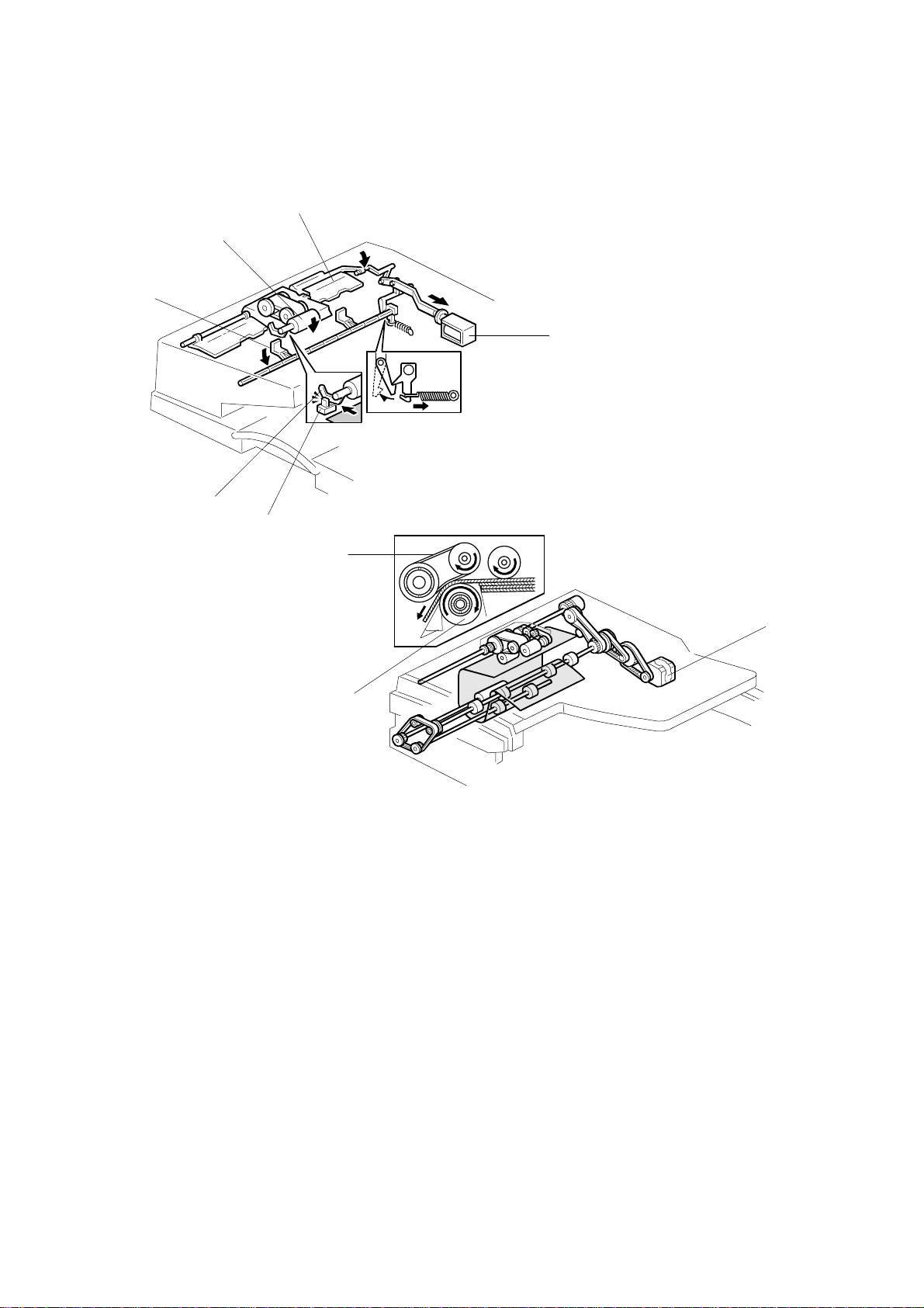
3.2 FEED UNIT
1. Open the DF feed cover [D] and
detach the strap [E] (# x 1).
2. Raise the front guide flap [F] to
about a 45-degree angle, and
push the feed unit [G] into the
spring so that it comes free.
NOTE: 1) The feed unit comes off
very easily if you first lift
flap [H] to about a 45degree angle.
2) When re installing, be
sure that the lever [I] is
above the pin [J].
[C]
[J]
[I]
[D]
[F]
[A]
[B]
B387R110.WMF
[E]
[G]
[H]
B387R101.WMF
3.3 SEPARATION ROLLER
1. Feed unit (☛ 3.2)
2. Roller cover [K]
3. Separation roller [L] (# x 1).
B387-15
[L]
[K]
Peripherals
B387R105.WMF
Page 17

PICK-UP ROLLER 20 February, 2001
3.4 PICK-UP ROLLER
[B]
[A]
[C]
B387R102.WMF
1. Feed unit (☛ 3.2)
2. Remove 2 clip rings and 1 bushing [A]
3. Pull the shaft [B] part way out at the gear end, so that the pick-up roller [C] can
be taken off.
3.5 FEED BELT
[F]
[D]
B387R103.WMF
[E]
1. Feed unit (☛ 3.2)
2. Pick-up roller housing [D]
3. Push down on the lower wings [E] of the tensioning piece [F], so that the
tensioning piece comes free of the shaft.
B387R104.WMF
[G]
4. Take the tensioning piece out, and then remove the belt [G].
B387-16
Page 18

20 February, 2001 ORIGINAL SENSORS (WIDTH, LENGTH, TRAILING EDGE)
3.6 ORIGINAL SENSORS (WIDTH, LENGTH, TRAILING
EDGE)
[A]
B387R107.WMF
[E]
[F]
[D]
B387R108.WMF
1. Original table (☛ 3.1.2)
2. Sensor platform [A] (! x 3).
3. Length sensors [B], [C] (1 connector on each sensor)
NOTE: Replace both sensors at the same time, together with the wiring and
connectors.
4. Width sensors [D], [E], and trailing edge sensor [F] (" x 1 on each sensor)
NOTE: Replace all three sensors at the same time, together with the wiring
and connectors.
[B]
[C]
Peripherals
B387-17
Page 19

ORIGINAL SET SENSOR 20 February, 2001
3.7 ORIGINAL SET SENSOR
[B]
[A]
B387R109.WMF
1. Original entrance guide (☛ 3.1.4)
2. Sensor bracket [A] (! x 1)
3. Original set sensor [B] (" x 1)
3.8 TRANSPORT MOTOR
[D]
[E]
[C]
B387R111.WMF
1. Rear cover (☛ 3.1.1)
2. Open the wire clamp [C] at the top of the motor bracket [D].
3. Motor bracket [D] (! x 2 , 1 spring)
NOTE: Unhook the spring at the board side.
4. Transport motor [E] (! x 2, " x 1)
B387-18
Page 20

20 February, 2001 FEED COVER OPEN SENSOR/
FEED CLUTCH/ROM/DF DRIVE BOARD
3.9 FEED COVER OPEN SENSOR/
FEED CLUTCH/ROM/DF DRIVE BOARD
[D]
[B]
[E]
Exterior
1. Rear cover (☛ 3.1.1)
[A]
[C]
B387R199.WMF
Feed Cover Open Sensor
2. Sensor bracket [A] (! x 1)
3. Feed cover open sensor [B] (! x 1)
Feed Clutch
2. Feed unit (☛ 3.2)
3. Feed clutch [C] (" x 1, 1 bushing, ! x 1).
NOTE: Pull the shaft inward until the clutch can be removed.
ROM
2. Replace the ROM [D] on the DF drive board.
DF Drive Board
2. DF drive board [E] (# x 3, all connectors)
B387-19
Peripherals
Page 21

REGISTRATION SENSOR 20 February, 2001
3.10 REGISTRATION SENSOR
[C]
[B]
[A]
B387R113.WMF
1. DF feed cover (☛ 3.1.5)
2. Original entrance guide (☛ 3.1.4)
3. Outer turn guide [A] (! x 2)
4. Pop out the inner turn guide [B], and remove the registration sensor [C] (" x
1)
3.11 PICK-UP SOLENOID
[D]
1. Rear cover (☛ 3.1.1)
2. Pick-up solenoid [D] (! x 2, " x 1)
B387-20
B387R112.WMF
Page 22

20 February, 2001 STAMP SOLENOID
3.12 STAMP SOLENOID
[B]
[A]
[D]
[C]
B387R114.WMF
1. Rear cover (☛ 3.1.1)
2. Disconnect the stamp solenoid connector.
NOTE: Pull out the small connector piece from the large connector. (The large
connector itself cannot fit through the hole in the frame.)
3. Lift the ADF upright and pull open the exit guide [A]. Release the front and rear
hooks [B] and open the cover [C].
4. Remove the stamp solenoid [D] (! x 1), and pull it out together with the wire.
Peripherals
B387-21
Page 23

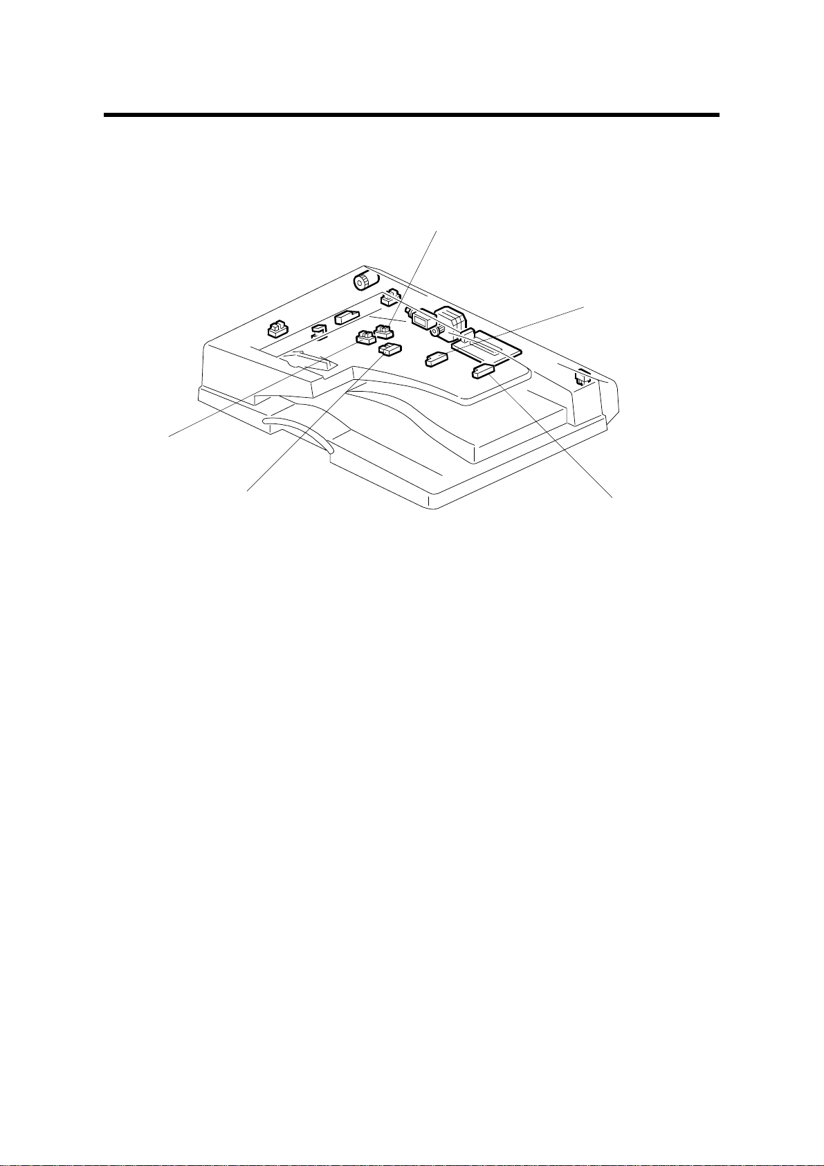
ELECTRICAL COMPONENT LAYOUT (B387)
1
14
13
2
3
4
5
12
6
11
10
9
8
7
B387V101.WMF
Symbol Name Index No. P-to-P
Motors
M1 DF Transport 4 J13
Sensors
S1 Registration 14 J14
S2 Original Set 12 J14
S3 DF Position 6 J14
S4 Feed Cover Open 2 J15
S5 Original Width 1 10 J15
S6 Original Width 2 11 J15
S7 Original Trailing Edge 9 J15
S8 Original Length 1 7 J16
S9 Original Length 2 8 J16
Solenoids
SOL1 Stamp 13 J13
SOL2 DF Pick-up 3 J14
Magnetic Clutches
MC1 DF Feed 1 J13
PCBs
PCB1 DF Drive 5 I13-16
 Loading...