

Page 1

AUTO REVERSE DOCUMENT
FEEDER (A661)
Page 2

30 November 1996 OVERALL MACHINE I NFO R M ATI O N
1. OVERALL MACHINE INFORMATION
1.1 SPECIFICATIONS
Original Size: Standard Size
Single-sided Mode: A3 to A5, DLT to HLT
Double-sided Mode: A3 to A4, DLT to LT
Non-standard Size (Single-sided Mode only)
Max. width 297 mm
Min. width 105 mm
Max. length 1260 mm
Min. length 128 mm
Original Weight : 45 kg to 90 kg
Table Capacity : 30 sheets (70 kg)
Original Standard Position: Rear left corner
Separation: FRR
Original Transport: Roller transport
Original Feed Order: From the top original
Reproduction Range: 37 to 150%
Power Source: 24 & 5 Vdc from the copier
Power Consumption: 50 W
Dimensions (W x D x H): 550 x 470 x 130 mm
Weight: 11 kg
A661-1
Options
Page 3
OVERALL MACHINE INFORMATION 30 November 1996
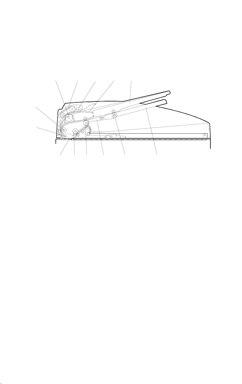
1.2 MECHANICAL COMPONENT LAYOUT
1
13
12
11
1. Separation Roller
2. Paper Feed Belt
2
3
910
4
8
5
7
6
A661V500.wmf
8. Junction Gate
9. Original Exit Roller
3. Pick-up Roller
4. Original Entrance Guide
5. Original Table
6. Reverse Table
7. Reverse Roller
10. 2nd Transport Roller
11. DF Exposure Glass
12. Original Exposure Guide
13. 1st Transport Roller
A661-2
Page 4
30 November 1996 OVERALL MACHINE I NFO R M ATI O N
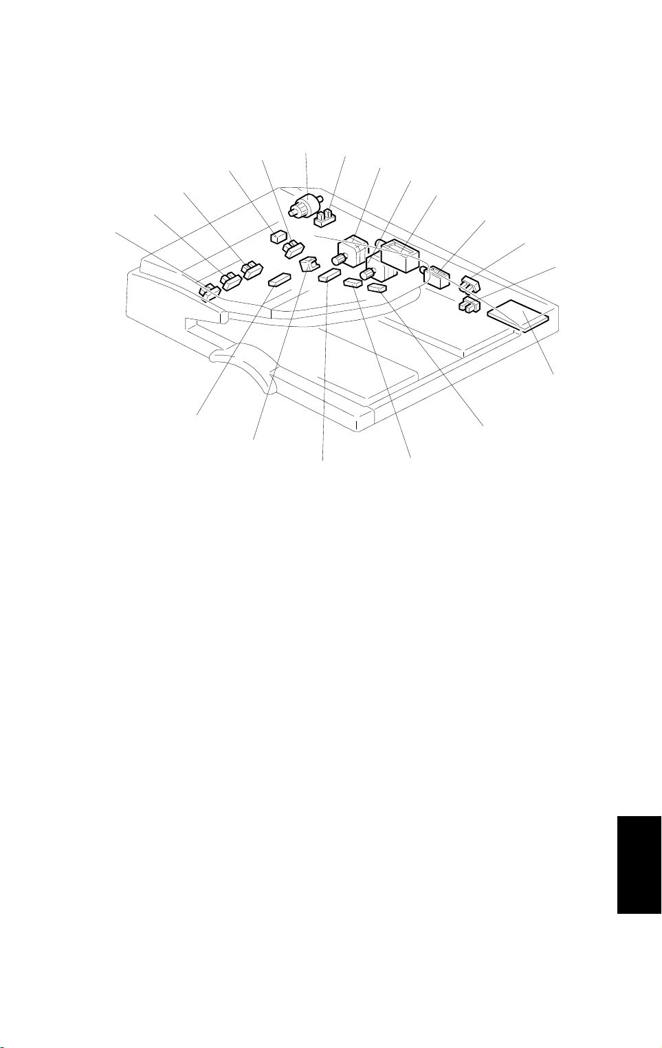
1.3 ELECTRICAL COMPONENT LAYOUT
1
18
19
17
16
15
2
3
4
5
6
7
8
9
14
13
1. DF Feed Clutch
2. Feed Cover Open Sensor
3. DF Transport Motor
4. DF Feed Motor
5. DF Pick-up Solenoid
6. Junction Gate Solenoid
7. DF Position Sensor
8. APS Start Sensor
9. DF Drive PCB
10. Original Length Sensor 2
10
12
11
A661V501.wmf
11. Original Length Sensor 1
12. Reverse Table Sensor
13. Stamper Solenoid
14. Original Exit Sensor
15. Original Width Sensor 3
16. Original Width Sensor 2
17. Original Width Sensor 1
18. Original Set Sensor
19. Registration Sensor
A661-3
Options
Page 5

OVERALL MACHINE INFORMATION 30 November 1996
1.4 ELECTRICAL COMPONENT DESCRIPTION
Symbol Name Function Index
No.
Motors
M1 DF Feed Drives the feed bel t , separation, pic k- up, and
reverse table rollers.
M2 DF Transport Drives the transport and exit roll ers 3
Sensors
S1 APS Start Informs the CPU when the DF is opened and
closed (for platen mode) so that ori gi nal size
sensors in the copi er can check the ori gi nal size.
S2 DF Position Detects whether the DF is lifted or not. 7
S3 Registration Detects the leadi ng edge of the original to turn off
the DF feed and tran sport motors, det ect s t h e
original exposure timing, and checks for orig i nal
misfeeds.
S4 Feed Cover Open
Sensor
S5 Original Wi dt h - 1 Detects the original width. 17
S6 Original Wi dt h - 2 Detects the original width. 16
S7 Original Wi dt h - 3 Detects the original width. 15
S8 Original Lengt h - 1 Detects the original length. 11
S9 Original Lengt h - 2 Detects the original length. 10
S10 Original Set Detects if an origi nal is on the feed tabl e. 18
S11 Original Exit Detects the leading edge of the original to turn on
S12 Reverse Table Detects the trail i ng edge of the original to turn on
Solenoids
SOL1 DF Pick-up Controls the up-down movement of the origina l
SOL2 Stamper Energizes the stamper to mark the origin al . 13
SOL3 Junction Gate Opens and close s the junction gate. 6
Clutches
MC1 DF Feed Transfers trans por t motor drive to the pick-up
PCBs
PCB1 DF D rive Interfac es the sensor signal s with the copier, and
Detects whether the feed-in cov er is o pened or
not.
the junction gate solenoid and checks for original
misfeeds.
Detects the trail i ng edge of the original to turn off
the transport and feed motor and jun ct i on gate
solenoid.
the DF feed clutc h fo r next original an d checks
for original m i sf eeds.
table.
roller and feed belt.
transfers the magnetic clutch, solenoid and motor
drive signals from the copier.
4
8
19
2
14
12
5
1
9
A661-4
Page 6
30 November 1996 OVERALL MACHINE I NFO R M ATI O N
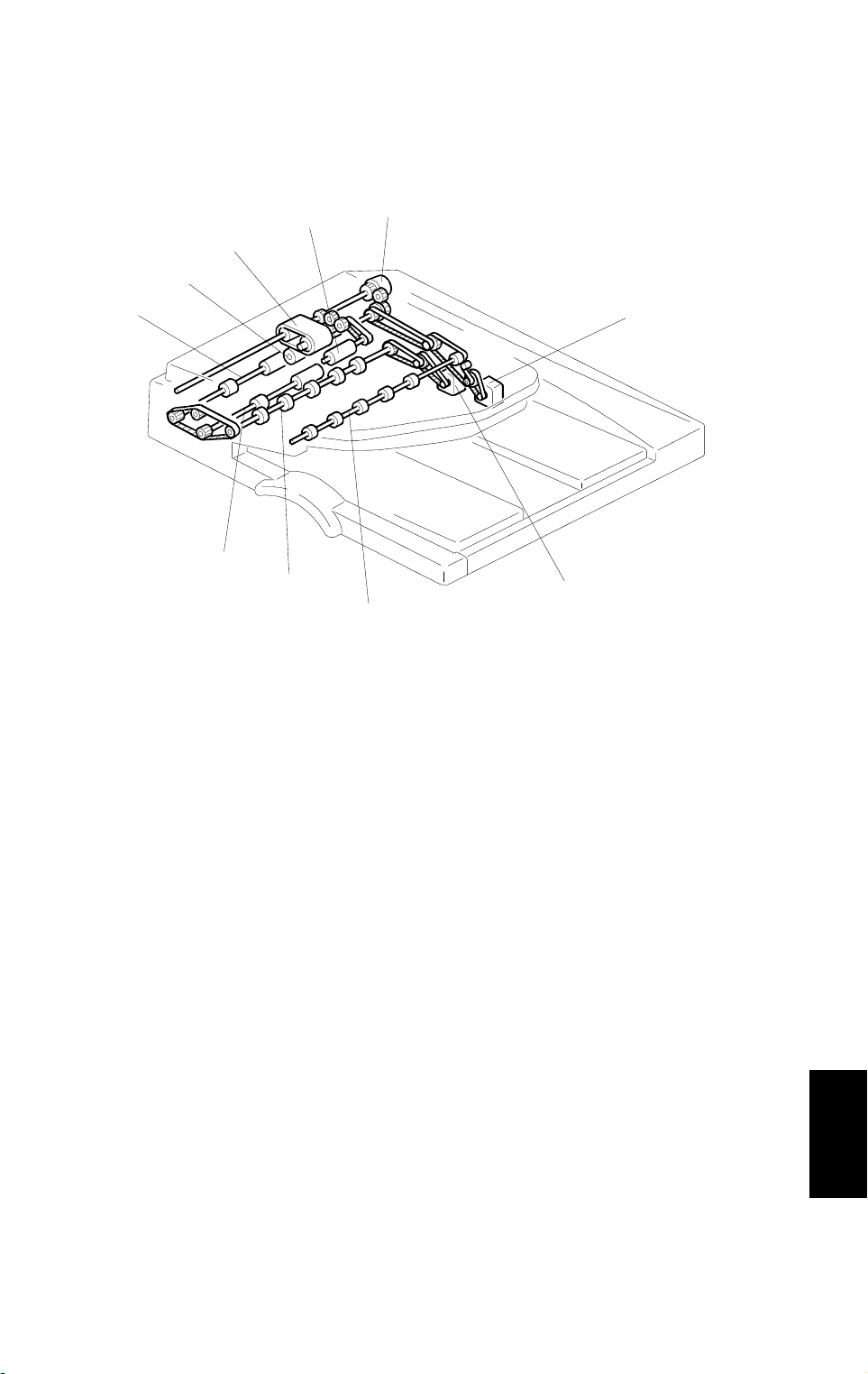
1.5 DRIVE LAYOUT
10
1
9
8
7
2
6
5
3
4
A661V502.wmf
1. DF Feed Clutch
2. DF Feed Motor
3. DF Transport Motor
4. Reverse Table Roller
5. Exit Roller
6. 2nd Transport Roller
7. 1st Transport Roller
8. Separation Roller
9. Original Feed Belt
10. Pick-up Roller
Options
A661-5
Page 7
DETAILED DESCRIPTIONS 30 November 1996
2. DETAILED DESCRIPTIONS
2.1 ORIGINAL SIZE DETECTION
[D]
[E]
A661D500.wmf
[C]
[B] [A]
The DF has three width sensors (- 1 [A], - 2 [B], and - 3[C]) to detect the
original width and two original length sensors (-1 [D] and -2 [E]) to detect the
original length. The DF detects the original size through the combination of
those five sensors as shown in the table on the next page.
When using an original of a non-standard size, the user needs to input the
original length at the operation panel.
A661-6
Page 8

30 November 1996 DETAILED DESCRIPTIONS
A3 (297 x 420)
B4 (257 x 364)
A4 (Lengthwise)
(210 x 297)
A4 (297 x 210) (Si dew ays)
B5 (182 x 257)
(Lengthwis e)
B5 (257 x 182) (Si dew ays)
A5 (148 x 210)
(Lengthwis e)
A5 (210 x 148) (Si dew ays)
11" x 17" (DLT)
11" x 15"
10" x 14"
8.5" x 14" (LG)
8.5" x 13" (F4)
8" x 13" (F)
8.5" x 11" (Lengt hwi se)
8.5" x 11" (Sideways)
10" x 8" (Lengthwi se)
5.5" x 8.5" (Len gt hw ise)
(HLT)
5.5" x 8.5" (Sidew ays)
(HLT)
NA EU Original
Width-1
✗❍
✗❍
✗❍
✗❍
✗❍
✗❍
✗✗
✗❍
❍✗
❍✗
❍✗
❍✗
✗❍
❍❍
❍✗
❍✗
❍✗
❍✗
❍✗
ON ON ON ON ON
ON ON – ON ON
ON – – ON –
ON ON ON – –
–––ON–
ON ON – – –
–––––
ON––––
ON ON ON ON ON
ON ON ON ON ON
ON ON – ON ON
ON – – ON ON
ON – – ON ON
ON – – ON ON
ON – – ON –
ON ON ON – –
ON – – ON –
–––––
ON––––
Original
Width-2
Original
Width-3
Original
Length-1
Original
Length-2
Key
✗: No, ❍: Yes
ON: Paper present
Options
A661-7
Page 9
DETAILED DESCRIPTIONS 30 November 1996
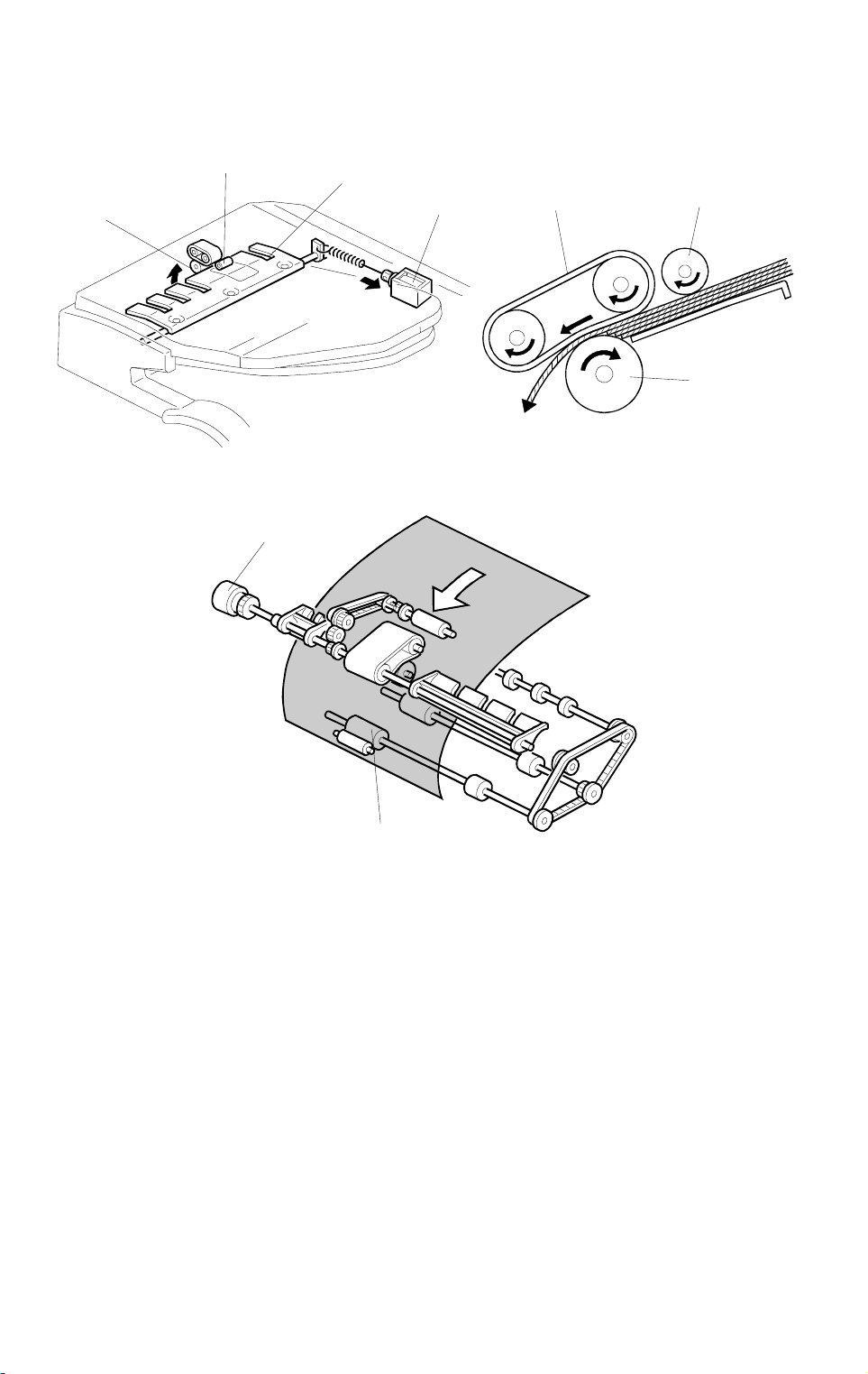
2.2 PICK-OFF AND SEPARATION MECHANISM
[F]
[B]
[D]
[C]
A661D502.wmf
[A]
[E]
[B]
[F]
A661R515.wmf
[G]
A661D501.wmf
When the print key is pressed, the DF pick-up solenoid [A] turns on and the
originals are lifted up to the pick-up roller [B] by the entrance guide [C]. At the
same time, the DF feed clutch [D] turns on.
At 200 ms after this, the DF feed motor turns on. The original is fed to the
paper feed belt [E] from the top page. The pages are separated by the
separation roller [F] and the top sheet of the original is fed to the 1st transport
roller [G]. The original separation system uses the FRR system.
A661-8
Page 10
30 November 1996 DETAILED DESCRIPTIONS
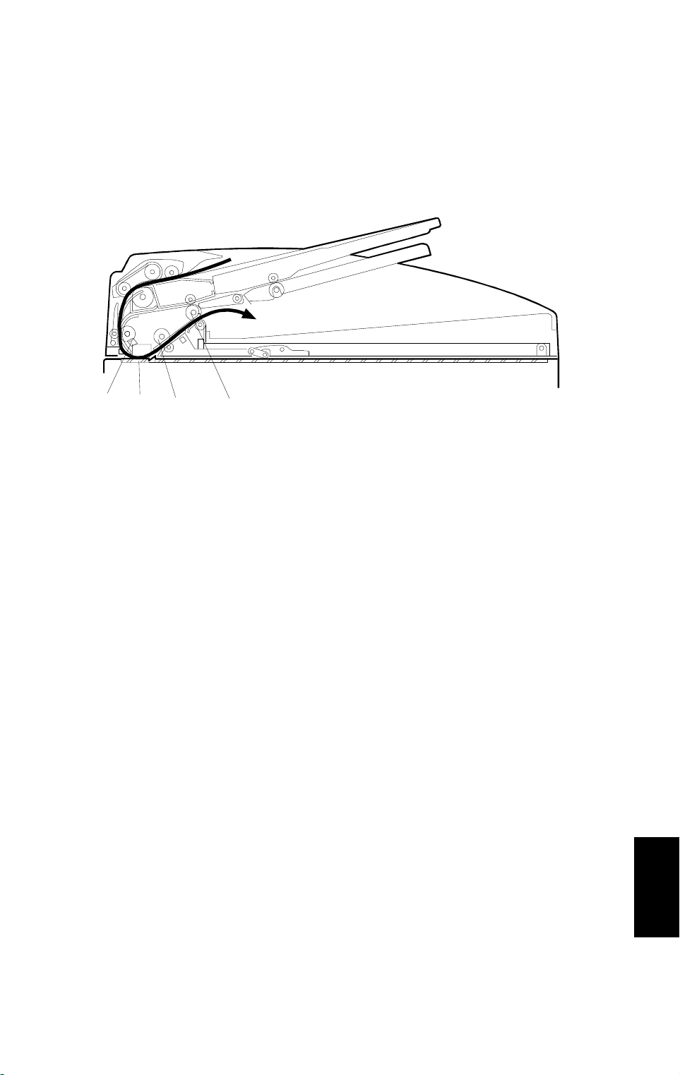
2.3 ORIGINAL TRANSPORT AND EXIT MECHANISM
2.3.1 Single-sided Original
[A]
[B]
[C]
[D]
A661D503.wmf
When the leading edge of the original reaches the registration sensor [A], the
DF feed and transport motors turn off. After a short time the DF feed and
transport motors turn on again. The original is fed to the DF exposure glass
[B] and it is scanned in this area.
The original is fed through to the 2nd transport roller [C] and fed out by the
exit roller [D].
The DF feed motor speed while feeding the original to the registration sensor
is 59.4 mm/s. However, when the motor turns on again to feed the original to
the exposure glass, the speed depends on the selected reproduction ratio. At
100%, it is 90 mm/s.
Options
A661-9
Page 11
DETAILED DESCRIPTIONS 30 November 1996
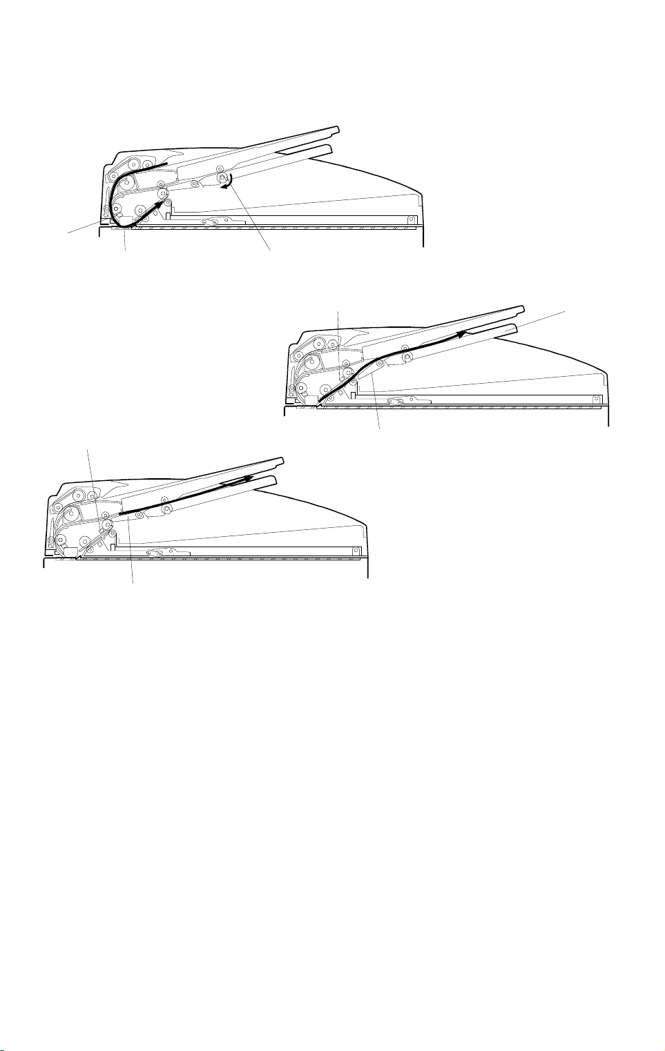
2.3.2 Double-sided Original
[A]
[B][C]
[D]
A661D516.wmf
[D]
[C]
[F]
A661D517.wmf
[E]
A661D518.wmf
1. When the leading edge of the original reaches the registration sensor [A]
the DF feed and transport motors turn off. After a short time, the DF feed
motor turns on and the DF transport motor turns on in reverse to drive the
reverse table roller [B]. The original is fed to the DF exposure glass [C]
and it is scanned in this area.
2. When the leading edge of the original reaches the exit sensor [D], the
junction gate solenoid turns on and the junction gate [E] is opened. The
original is transported to the reverse table [F] to reverse the original.
3. 33 mm after the trailing edge of the original reaches the exit sensor [D],
the junction gate solenoid turns off and the junction gate [E] closes. At the
same time, the DF feed and transport motors turn off.
A661-10
Page 12

30 November 1996 DETAILED DESCRIPTIONS
[A]
A661D519.wmf
A661D520.wmf
4. After a short time, both motors turn on in the same direction and the
original is fed to the 1st transport roller [A].
5. The original is fed and exposed in the same way as in steps 1, 2 and 3, to
copy the reverse side.
6. The original is fed out to the original exit tray.
A661-11
Options
Page 13

DETAILED DESCRIPTIONS 30 November 1996
2.4 STAMP
[C]
[A]
[B]
A661D504.wmf
This function is only for fax mode.
There is a stamp [A] between the 2nd transport roller [B] and the exit roller
[C], and its solenoid is controlled by the copier directly.
When the original reaches the stamp position, the DF feed motor stops. At
300 milliseconds after stopping the DF feed motor, the stamper solenoid
turns on if the page was sent successfully (immediate transmission) or stored
successfully (memory transmission). After stamping, the DF feed motor starts
again for feeding out the document, and its speed is about 1.3 times the
normal speed.
The stamping position on the original can be changed by adjusting SP6-010.
A661-12
Page 14

30 November 1996 DETAILED DESCRIPTIONS
2.5 TIMING CHARTS
2.5.1 LT Sideways (Single-sided Original Mode)
Feed Motor
Transport Motor
DF
Pick-up Solenoid
DF Feed Clutch
Original Set
Sensor
Registration
Sensor
Original Exit
Sensor
Reverse Table
Sensor
F Gate
Junction Gate
Solenoid
200ms
JAM 1
JAM 3,4
JAM5,6
700ms
Jam conditions: Refer to Sectio n 2. 6 for details
.
F Gate: This signal goes high whe n the laser starts to wr i t e a page to the drum.
A661-13
A661D505.wmf
Options
Page 15

DETAILED DESCRIPTIONS 30 November 1996
2.5.2 LT Sideways-Stamper Mode (Single-sided Original Mode)
Feed Motor
Transport Motor
DF Feed Clutch
DF
Pick-up Solenoid
Original Set
Sensor
Registration
Sensor
Original Exit
Sensor
Reverse Table
Sensor
F Gate
Junction Gate
Solenoid
Stamper Solenoid
200ms
JAM 1
JAM 3,4
JAM5,6
300ms
100ms
700ms
420ms
300ms 100ms 300ms
A661D506.wmf
Jam conditions: Refer to Sectio n 2. 6 for details
.
F Gate: This signal goes high whe n the laser starts to wr i t e a page to the drum.
A661-14
Page 16

30 November 1996 DETAILED DESCRIPTIONS
2.5.3 LT Sideways (Double-sided Original Mode)
260ms
580ms
JAM 2,7
JAM 8
370ms 370ms
JAM5,6
JAM 3,4
JAM 1
200ms
Original Exit
Feed Motor
Transport Motor
DF Feed Clutch
DF
Pick-up Solenoid
Original Set
Jam conditions: Refer to Sectio n 2. 6 for details
Sensor
.
Registration
Sensor
Sensor
Sensor
F Gate
Reverse Table
Junction Gate
Solenoid
F Gate: This signal goes high whe n the laser starts to wr i t e a page to the drum.
Stamper Solenoid
A661D507.wmf
Options
A661-15
Page 17

DETAILED DESCRIPTIONS 30 November 1996
2.5.4 LT Sideways-Stamper Mode (Double-sid ed Original Mo de)
260ms
580ms
JAM 2,7
JAM 8
JAM 1
200ms
Feed Motor
Transport Motor
DF Feed Clutch
DF
Pick-up Solenoid
Original Set
Sensor
Jam condition s: Refer to Section 2.6 for details
JAM 3,4
Registration
Sensor
.
JAM5,6
Original Exit
Sensor
370ms
Reverse Table
Sensor
420ms
F Gate
Junction Gate
Solenoid
F Gate: This sig nal goes high when the laser starts to write a page to the drum.
100ms
300ms
Stamper Solenoid
A661D508.wmf
A661-16
Page 18

30 November 1996 DETAILED DESCRIPTIONS
2.6 JAM DETECTION
JAM 1:
JAM 2:
JAM 3:
JAM 4:
JAM 5:
JAM 6:
If the registration sensor does not turn on before the CPU judges that
the original was fed 255 mm since the DF feed motor turned on,
when the original was fed from the original tray.
If the registration sensor does not turn on before the CPU judges that
the original was fed 190 mm since the DF feed motor turned on,
when the original was fed from the reverse tray.
If the registration sensor does not turn off before the CPU judges that
the original was fed X1 mm since the registration sensor turned on.
Standard sizes : X1 = Original Size x 1.4
Non-standard sizes : X1 = 1765
If the original exit sensor does not turn on before the CPU judges
that the original was fed 140 mm since the registration sensor turned
on.
If the original exit sensor does not turn off before the CPU judges
that the original was fed X1 mm since the original exit sensor turned
on.
If the reverse table sensor does not turn on before the CPU judges
that the original was fed 180 mm since the original exit sensor turned
on.
JAM 7:
JAM 8:
If the reverse table sensor does not turn off before the CPU judges
that the original was fed X2 mm since the DF feed motor turned on
again.
X2 = Original Size x 1.4
If the reverse table sensor is off when the DF feed motor turns on
again.
Options
A661-17
Page 19

DETAILED DESCRIPTIONS 30 November 1996
2.7 OVERALL ELECTRICAL CIRCUIT
Copier IOCSS
Board
DF Drive Board
Driver
DF Connection
5 V
DF Feed/
Transport
Motor
M
Sensors
Clutch
and
Solenoids
A661D509.wmf
The DF pick-up solenoid, junction gate solenoid, stamper solenoid, and DF
feed clutch are directly controlled by the copier through the DF drive board.
The sensor signals are directly sent to the copier through the DF drive board.
The DF drive board has a driver for the DF feed and transport motors and
thier drive signals are sent from the copier.
When the DF connector is connected to the copier IOCSS board, the DF
connection signal to the copier goes to 5 V. Then the copier detects that the
ARDF is connected.
A661-18
Page 20

30 November 1996 INSTALLATION
3. INSTALLATION
[A]
[B]
[F]
A661I500.wmf
[E]
[C]
[H]
[G]
A661I501.wmf
[D]
[I]
[J]
[I]
A661I504.wmf
CAUTION
+
Unplug the copier power cord before starting the following procedure.
NOTE:
When installing the DF, use the tool [A] in the accessory bag or a
usual screw driver.
1. Unplug the document feeder. Then, remove all tapes.
2. Remove the left scale [B] (2 screws).
3. Place the DF exposure glass [C] on the glass holder. The white mark [D]
must be at the rear side facing down.
4. Peel off the backing [E] of the dou ble side ta pe a ttached to the rear si de of
the scale guide [F], the n instal l the sca le guide (2 scr ews remove d in step 2).
5. Affix the original size decal [G] on the scale guide.
NOTE:
Place the decal along the rear edge, and the left side flush with
the scale paper guide [H], as shown.
6. Install stud screws [I] and grounding plate [J] for the DF on the copier.
Options
A661-19
Page 21

INSTALLATION 30 November 1996
[A]
[B]
A661I502.wmf
[D]
[C]
A661I503.wmf
7. Install the DF unit [A].
8. Slide the DF to the left, then secure the DF unit with 2 screws (M4 x 10).
9. Connect the I/F harness [B] to the copier.
10. Affix the original direction decal [C] on the DF table as shown.
11. Affix the glass cleaning decal [D] on the DF cover as shown
if necessary
12. Turn the ac and main switches on. Then, check if the document feeder
works properly.
A661-20
.
Page 22

30 November 1996 PREVENTIVE MAINTENANCE
4. PREVENTIVE MAINTENANCE
EM 60K 120K 185K 240K NOTE
AUTO REVERSE DOCUMENT FEEDER
Transport Belt C R R R R Al cohol
Separation Roller C R R R R Alc ohol
Pick-up Roller C R R R R Alcohol
Stamper I Replace if ne cessary
White Plate C Alcohol
DF Exposure Glass C Alcohol
Platen Cover C Alcohol
(for originals)
A661-21
Options
Page 23

REPLACEMENT AND ADJUSTMENT 30 November 1996
5. REPLACEMENT AND ADJUSTMENT
5.1 ORIGINAL FEED UNIT REMOVAL
[A]
[B]
1. Open the DF feed cover.
2. Push the original feed unit to the front [A].
3. Release the rear joint of the original feed unit [B].
4. Remove the original feed unit.
A628O015.wmf
A661-22
Page 24

30 November 1996 REPLACEMENT AND ADJUSTMENT
5.2 SEPARATION ROLLER REPLACEMENT
[B]
[A]
[D]
[C]
1. Remove the original feed unit.
2. Open the entrance guide [A].
3. Remove the support guide [B] (1 screw).
4. Remove the snap ring [C].
5. Replace the separation roller [D].
A661R501.wmf
Options
A661-23
Page 25

REPLACEMENT AND ADJUSTMENT 30 November 1996
5.3 PICK-UP ROLLER REPLACEMENT
[B]
[A]
[C]
[A]
1. Remove the original feed unit.
2. Remove the two snap rings [A].
3. Pull out the pick-up roller shaft [B].
4. Replace the pick-up roller [C].
A661R502.wmf
A661-24
Page 26

30 November 1996 REPLACEMENT AND ADJUSTMENT
5.4 FEED BELT REPLACEMENT
[A]
[C]
[B]
[C]
[D]
A661R503.wmf
[G]
[E]
[I]
[F]
A661R504.wmf
[H]
[I]
[G]
[J]
A661R505.wmf
1. Remove the original feed unit.
2. Remove the front bushing [A], spring [B], and washers [C] (1 E-ring).
3. Remove the original guide [D] (1 E-ring).
4. Remove the snap ring [E] and the pick-up roller unit [F].
5. Release the idle roller holder [G] from the drive roller shaft.
6. Remove the idle roller [H], idle roller holder [G], and 2 springs [I].
7. Replace the feed belt [J].
Options
A661-25
Page 27

REPLACEMENT AND ADJUSTMENT 30 November 1996
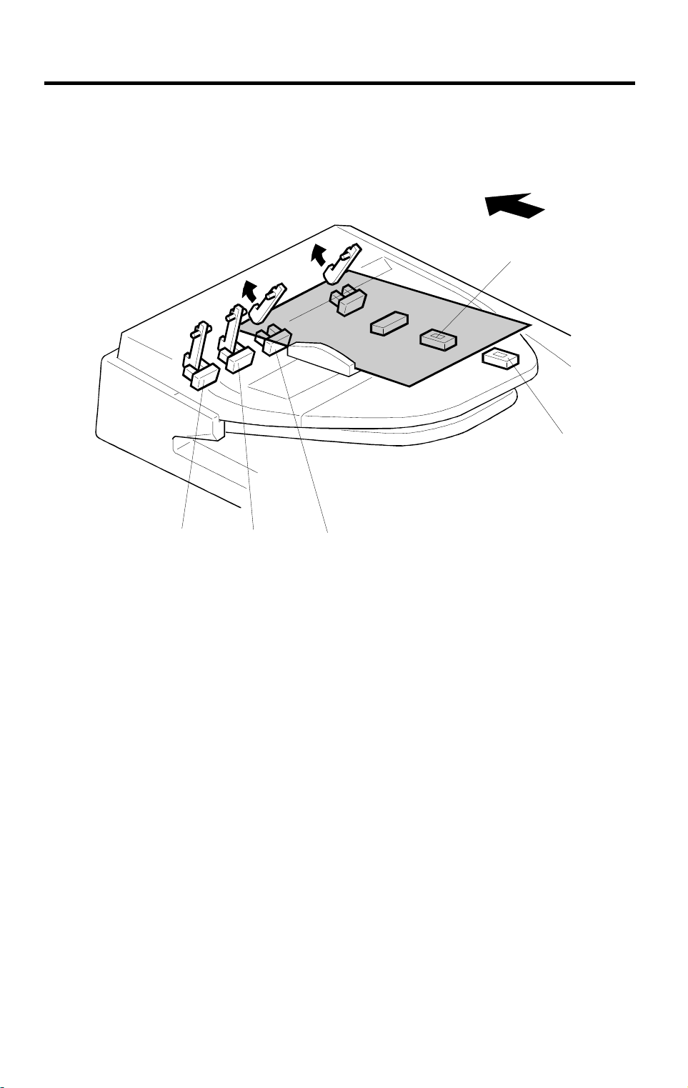
5.5 ORIGINAL SET SENSOR AND WIDTH SENSOR
REPLACEMENT
[A]
[C]
[D]
[E]
1. Open the DF feed cover.
2. Remove the entrance guide [A] (3 screws).
3. Replace the following sensors.
Original Set Sensor [B]
Original Width Sensor 1 [C]
Original Width Sensor 2 [D]
Original Width Sensor 3 [E]
[B]
A661R506.wmf
A661-26
Page 28

30 November 1996 REPLACEMENT AND ADJUSTMENT
5.6 DF COVER REMOVAL
[A]
1. Open the DF feed cover.
[C]
[D]
[B]
[E]
A661R507.wmf
2. Remove the front cover [A] (3 screws).
Remove the rear cover [B] (3 screws).
3. Remove the reverse table [D] (4 screws).
Remove the original table [C] (1 snap ring, 1 connector).
Remove the original exit table [E] (4 screws).
Options
A661-27
Page 29

REPLACEMENT AND ADJUSTMENT 30 November 1996
5.7 DF FEED COVER OPEN , DF POSITION, AND APS START
SENSOR REPLACEMENT
[B]
[C]
[A]
1. Remove the rear cover.
2. Replace the following sensors.
DF Feed Cover Open Sensor [A].
DF Position Sensor [B].
APS Start Sensor [C].
A661R508.wmf
A661-28
Page 30

30 November 1996 REPLACEMENT AND ADJUSTMENT
5.8 ORIGINAL LENGTH SENSOR REPLACEMENT
[D]
[A]
[B]
[C]
A661R509.wmf
1. Remove the original table.
2. Remove the original guide [A] (3 screws).
3. Replace the following sensors.
Original Length Sensor 1 [B]
Original Length Sensor 2 [C]
Reverse Table Sensor [D]
A661-29
Options
Page 31

REPLACEMENT AND ADJUSTMENT 30 November 1996
5.9 DF FEED CLUTCH, DF PICK-UP SOLENOID, AND
JUNCITON SOLENOID GATE REPLACEMENT
[C]
[B]
1. Remove the rear cover.
2. Replace the following clutch and solenoids.
DF Feed Clutch [A] (2 E-rings, 1 connector)
DF Pick-up Solenoid [B] (2 screws, 1 snap ring, 1 connector)
Junction Gate Solenoid [C] (2 screws, 1 snap ring, 1 connector)
[A]
A661R510.wmf
A661-30
Page 32

30 November 1996 REPLACEMENT AND ADJUSTMENT
5.10 REGISTRATION SENSOR REPLACEMENT
[D]
[F]
[E]
[G]
A661R511.wmf
[B]
[A]
[C]
1. Remove the front and rear cover.
2. Remove the original feed unit [A].
3. Remove the DF feed cover [B] (1 screw).
4. Remove the upper transport guide [C] (2 screws).
5. Remove the lower transport guide [D] (2 screws).
6. Remove the idle roller unit [E] (4 screws).
7. Remove the original exposure guide [F] (1 screw).
8. Replace the registration sensor [G] (1 screw, 1 connector).
A661R512.wmf
A661-31
Options
Page 33

REPLACEMENT AND ADJUSTMENT 30 November 1996
5.11 ORIGINAL EXIT SENSOR REPLACEMENT
[B]
[A]
[C]
[D]
A611R513.wmf
1. Remove the front and rear cover.
2. Release the lever [A] and open the original guide [B].
3. Remove the original exposure guide [C] (1 screw).
4. Remove the upper original guide [D] (4 screws, 1 connector).
5. Replace the original exit sensor from the upper original guide (1 screw, 1
connector).
A661-32
Page 34

30 November 1996 REPLACEMENT AND ADJUSTMENT
5.12 STAMPER SOLENOID REPLACEMENT
[B]
[C]
[A]
A661R514.wmf
1. Remove the front cover, rear cover, original table, reverse table, and
original exit tray.
2. Release the lever and open the original guide [A].
3. Remove the lower original guide [B] (2 screws).
4. Replace the stamper solenoid [C] (1 screws, 1 connector).
Options
A661-33
 Loading...