

Page 1

AUTO REVERSE
DOCUMENT FEEDER
(Machine Code: A663)
Page 2

30 March, 1999 MECHANICAL COMPONENTS
1. SPECIFICATIONS
Original Size and Weight: Thick original mode (default mode)
Use this setting for normal paper types
Maximum A3, 11" x 17"
Minimum B6 (sideways), 5
Weight 52 ~ 128 g/m2 (14 ~ 34 lbs.)
Thin original mode
Maximum A3, 11" x 17"
Minimum B6, 5
1/2
" x 8
Weight 40 ~ 128 g/m2 (11 ~ 34 lbs.)
Auto reverse mode
Maximum A3, 11" x 17"
Minimum B5, 5
1/2
" x 8
Weight 52 ~ 105 (14 ~ 27 lbs.)
Original Feed: Automatic feed - ADF mode
Manual feed one by one - SADF mode
Auto Reverse Feed - ARDF mode
1/2
1/2
1/2
" x 8
1/2
"
"
"
Original Table Capacity: 50 sheets at 80 g/m2 (21 lbs.)
Original Placement: Face up, first sheet on top
Original Separation: Feed Roller and Friction Belt
Original Transport: One flat belt
Power Consumption: 45 W
Power Source:
24 V ± 10% from the copier, 1.8 A
Dimensions (W x D x H): 610 x 507 x 130 mm (24.0" x 20.0" x 5.1")
Weight: Approximately 10.5 kg (23.2 lbs.)
1 to 1 Copying Speed
Capability
40 cpm
(A4/LT sideways)
Original Transport Speed 555 mm/s
Time Needed for Original
Replacement (A4
sideways)
590 ms
(thin original mode)
690 ms
(thick original mode)
Peripherals
A663-1
Page 3
MECHANICAL COMPONENTS 30 March, 1999
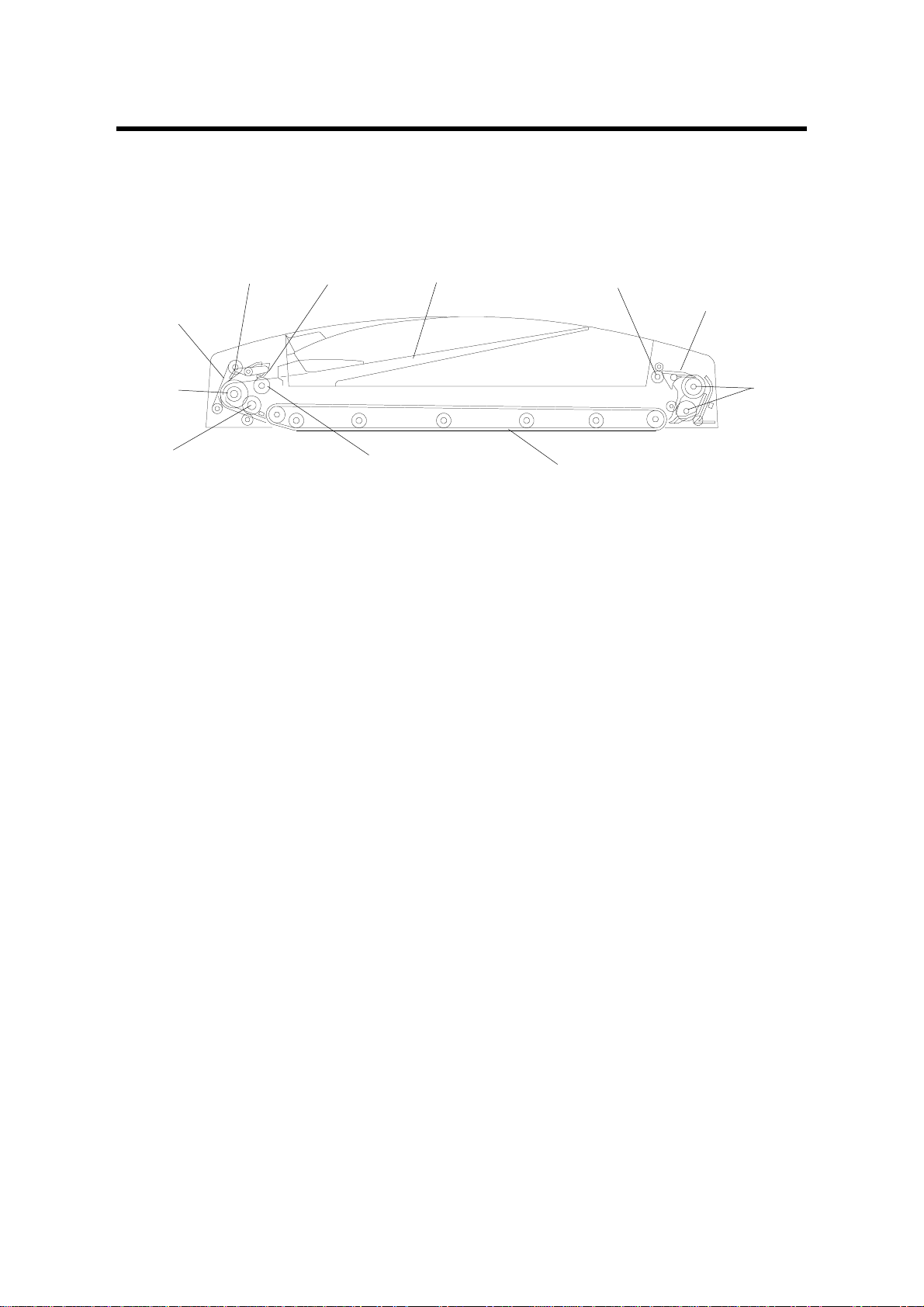
2. COMPONENT LAYOUT
2.1 MECHANICAL COMPONENTS
12 3
11
10
9
1. Original Stopper
2. Press Lever
3. Original Table
4. Exit Rollers
5. Inverter Pawls
4
5
6
A663V502.WMF
8
7. Transport Belt
8. Pick-up Rollers
9. Pull-out Roller
10. Feed Roller
11. Friction Belt
7
6. Inverter Rollers
A663-2
Page 4
30 March, 1999 ELECTRICAL COMPONENTS
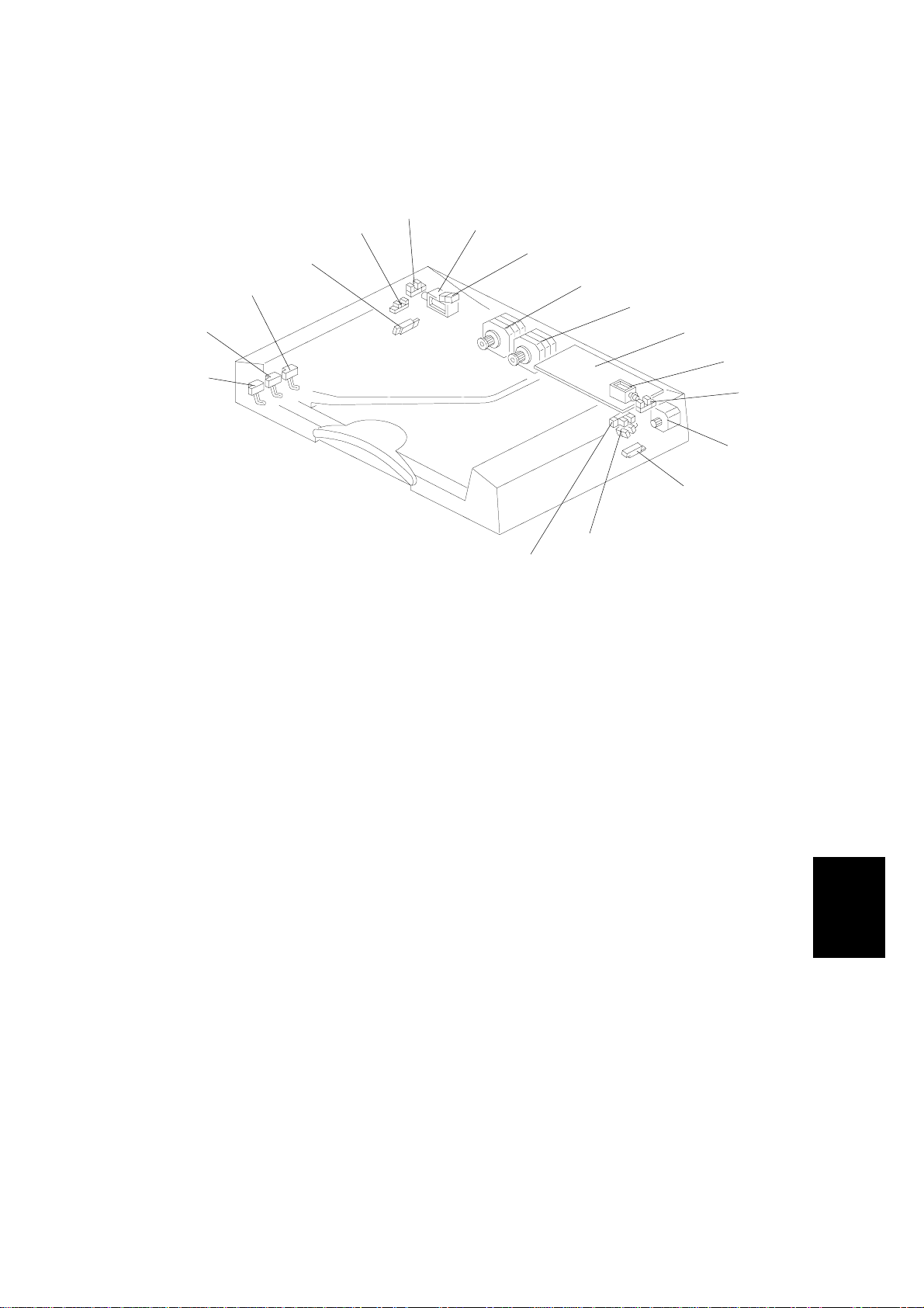
2.2 ELECTRICAL COMPONENTS
15
14
17
16
A663V503.WMF
2
1
3
4
5
6
7
8
9
10
11
12
13
1. Original set sensor
2. Feed –in Cover Open Sensor
3. Stopper Solenoid
4. Indicator Panel Lamps
5. Feed-in Motor
6. Belt Drive Motor
7. DF Main Board
8. Inverter Solenoid
9. Feed-out Cover Open Sensor
10. Feed-out Motor
11. Feed-out Sensor
12. APS Start Sensor
13. DF Position Sensor
14. Original width Sensor-1
15. Original width Sensor-2
16. Original Width Sensor-3
17. Registration Sensor
Peripherals
A663-3
Page 5

ELECTRICAL COMPONENTS 30 March, 1999
3. ELECTRICAL COMPONENT DESCRIPTION
Symbol Name Function Index No.
Motors
M1 Feed-in
M2 Belt Drive Drives the transport belt 6
M3 Feed-out Drives the feed-out and the inverter
Sensors
S1 Original Set Detects whether originals have been
S2
S3 Feed-out Cover
S4 Feed-out
S5 APS Start Informs the CPU that it is time to detect
S6 DF Position
S7 Original Width-1 Detects the width of the original 14
S8 Original Width-2 Detects the width of the original 15
S9 Original Width-3 Detects the width of the original 16
S10 Registration Determines original stop timing and
Solenoids
SOL1 Stopper
SOL2 I nvert er Energizes to invert the original when
PCB
PCB1 DF Main Board Controls all DF functions 7
Indicators (Lamps)
L1 Ready
L2 Auto Informs the operator that the auto feed
Feed-in Cover
Open
Open
Drives the feed-in system (pick-up feed
and pull-out rollers separation belt)
system
placed on the original table
Informs whether the feed-in cover is open
or not
Informs whether the feed-out cover is
open or not
Checks for original misfeeds and
determines original stop timing when in
auto-reverse mode
the original size (in platen mode)
Informs the CPU whether the DF is in the
up or down position
measures the length of the original
Lifts the original stopper and lowers the
feed-in lever to feed the set of originals to
the feed roller
copying two-sided originals
Informs the operator that the DF is in the
down position.
mode is available.
5
10
1
2
9
11
12
13
17
3
8
4
4
A663-4
Page 6
30 March, 1999 ORIGINAL PICK-UP MECHANISM
4. DETAILED DESCRIPTIONS
4.1 ORIGINAL PICK-UP MECHANISM
[B]
[C]
[D]
[A]
[E]
A663D514.WMF
When an original is placed on the table, the leading edge is stopped by the stopper
[A], and the feeler activates the original set sensor [B]. The Insert Original indicator
light goes out and the DF informs the copier's CPU that the originals have been
set.
When the Print key is pressed, the stopper solenoid [C] activates to raise the
stopper to allow the originals to be fed in, and to lower the press lever [D] to press
the originals against the pick-up rollers [E].
An anti-static brush [F] is installed to eliminate static electricity caused during the
original pick-up process.
[F]
A663-5
Peripherals
Page 7
SEPARATION AND PAPER FEED MECHANISM 30 March, 1999
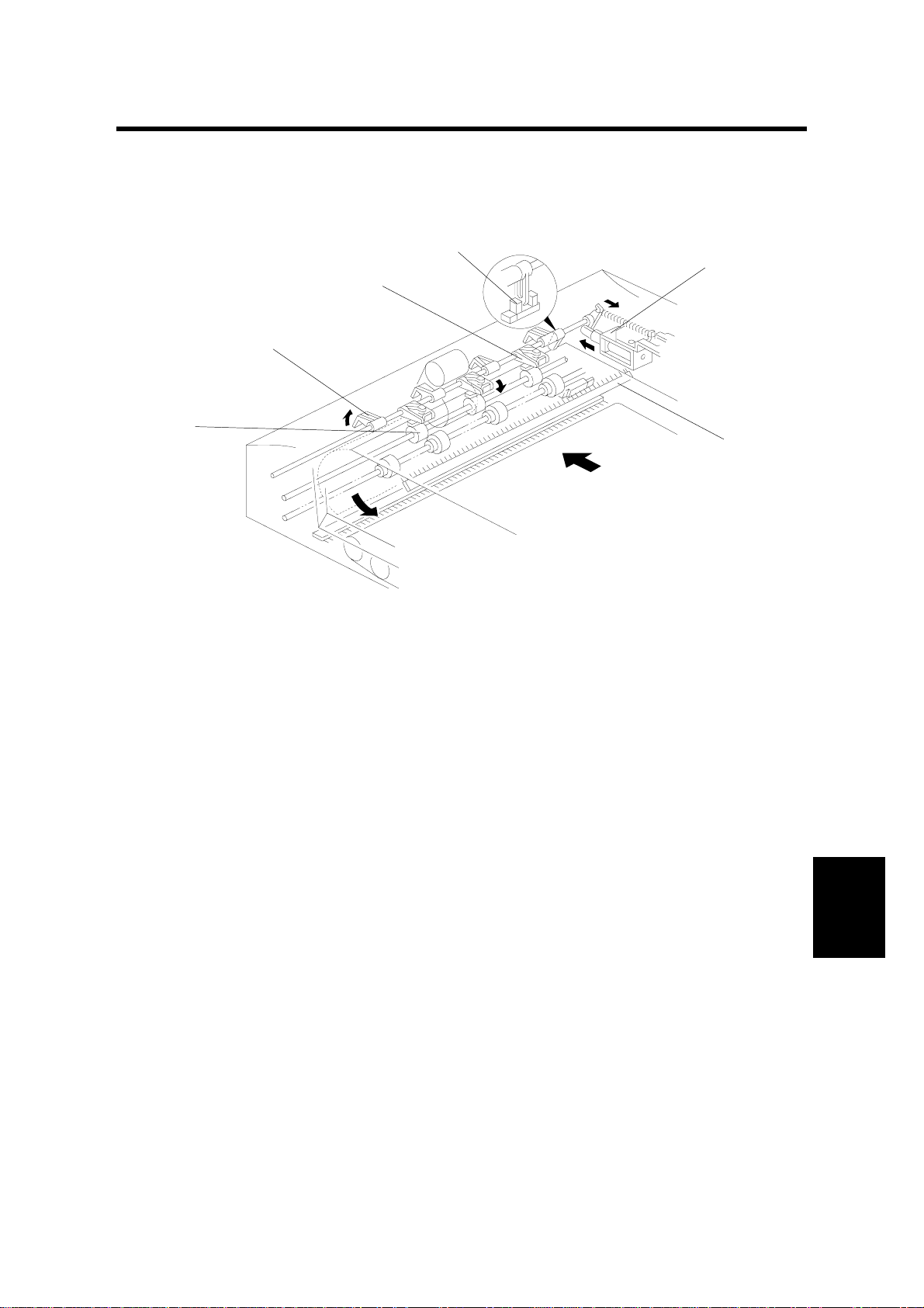
4.2 SEPARATION AND PAPER FEED MECHANISM
[D]
[A]
[E]
[B]
A663D515.WMF
[F]
[C]
[D]
[E]
[A]
A663D516.WMF
[B]
Originals are separated using the friction belt [A] and the feed roller [B]. When the
copier sends a signal to the DF to feed in the original, the feed-in motor [C] starts
rotating (clockwise) to drive the pick-up [D], feed and pull-out [E] rollers. A one-way
bearing stops the friction belt from rotating. Originals are separated and fed in one
by one because the resistance of the stationary friction belt is greater than the
friction between pages of the original.
When the registration sensor [F] detects the separated first original, the feed-in
motor reverses (counter clockwise), and the drive is transmitted only to the pull-out
rollers due to a one-way bearing. In this condition, the pull-out rollers are still
rotating in the same direction, and they feed the original to the exposure glass. The
motor turns off when the trailing edge of the 1st original has finished passing over
the sensor.
To prepare the next original, the feed-in motor turns clockwise to separate the
second original and the motor turns off when the registration sensor detects the
second original. When it is time for the second original to be fed to the exposure
glass, the feed-in motor turns counter clockwise.
A663-6
Page 8
30 March, 1999 FRICTION BELT DRIVE MECHANISM
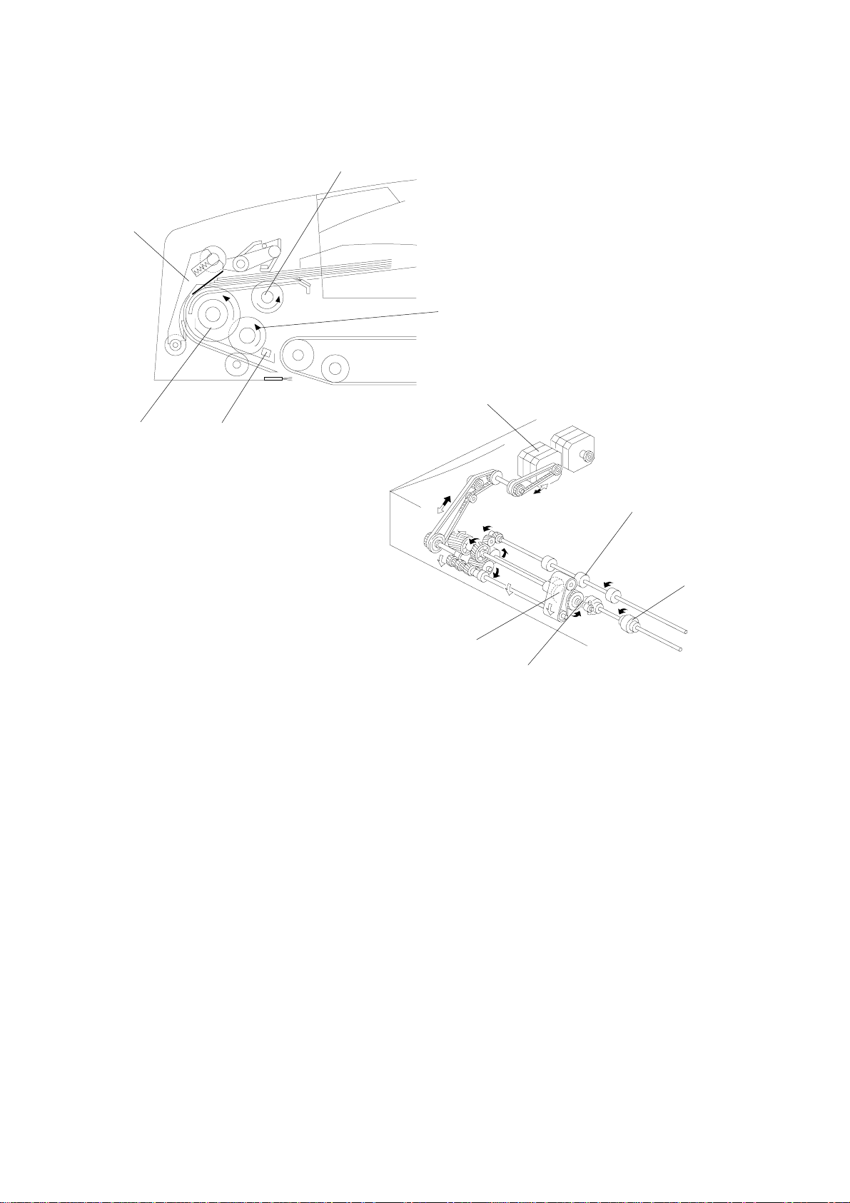
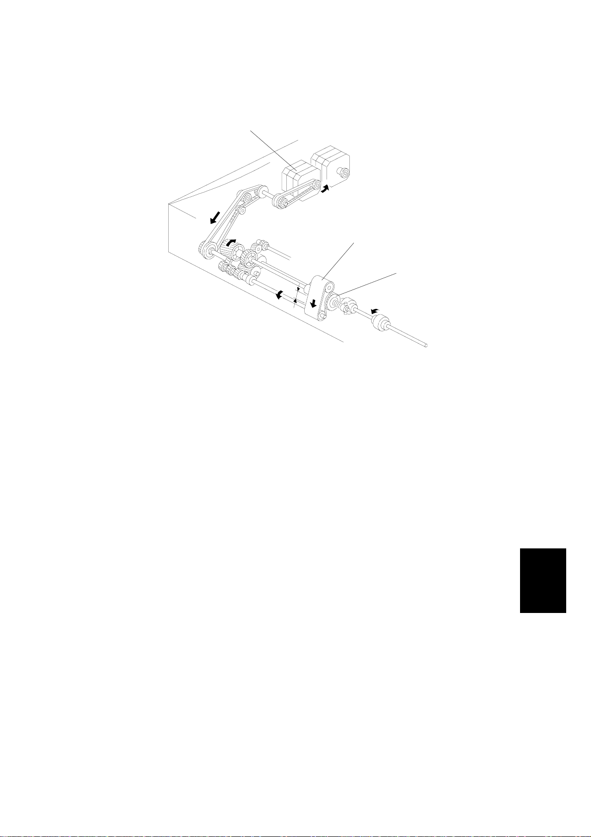
4.3 FRICTION BELT DRIVE MECHANISM
[A]
[B]
[C]
A663D517.WMF
The feed-in motor [A] drives the friction belt [B] through timing belts and gears. The
one-way bearing allows the belt to rotate in the direction shown only when the
feed-in motor is rotating counterclockwise. (The feed-in motor rotates
counterclockwise when the original is passing over the registration sensor, and
only the pull-out rollers are rotating to feed the paper to the exposure glass.)
As a result of this operation, the part of the friction belt that contacts the feed roller
[C] or the original changes. This prevents multiple feeding or causing originals to
become dirty.
The reverse movement of the friction belt will not affect the next original because
the pressure of the press lever holds the originals in place.
Peripherals
A663-7
Page 9

ORIGINAL SIZE DETECTION 30 March, 1999
4.4 ORIGINAL SIZE DETECTION
[C]
[B]
A663D518.WMF
[A]
The DF detects original width using three original width sensors-1 [A], -2 [B] and -3
[C]. It also detects the original length using the registration sensor.
The DF CPU counts the feed-in motor's drive pulses during the on timing of the
registration sensor. Based on this pulse count, the CPU determines the original
length.
The machine detects the original size by the total combination of all four sensors.
A663-8
Page 10

30 March, 1999 PAPER TRANSPORT MECHANISM
4.5 PAPER TRANSPORT MECHANISM
[A]
[C]
[B]
A663D519.WMF
Rear Scale
Left Scale
Original
3.5 mm
A663D520.WMF
An independent motor called the belt drive motor [A] (a dc stepper motor) drives
the transport belt [B]. The belt drive motor starts rotating soon after the copier
sends an original feed-in signal.
Inside the transport belt are four pressure roller shafts, which achieve the proper
amount of pressure between the belt and the original. The pressure roller shaft [C]
closest to the left original scale is made of rubber for the stronger pressure that is
required when in the thick original mode (this is the mode used for normal paper).
The other rollers are sponge rollers.
Since the copier's original alignment position is at the left rear corner (not in the
center), the originals fed from the DF must also be at this position. But if the
original was to be fed along the rear scale, unnecessary original skew, jam or
wrinkling may occur.
Peripherals
To prevent such problems, the original transfer position is set to 3.5 mm away from
the rear scale as shown. The correction for this 3.5 mm gap is compensated for by
the position of the lens unit. (Also see "Horizontal Lens Positioning" in the Optics
section of the manual for the copier main body.)
A663-9
Page 11

THICK/THIN ORIGINAL MODES 30 March, 1999
4.6 THICK/THIN ORIGINAL MODES
Fig. 1
[A]
Fig. 2
Fig. 3
A663D521.WMF
This document feeder has two different ways of stopping originals at the correct
position on the exposure glass. The technician can select one of these using a
copier SP mode. The user can also select the mode.
1. Thick Original Mode (Normal Paper Mode)
This mode is the factory set mode. The belt drive motor remains energized to
carry the original approximately 7 mm pass the left scale (Figures 1 and 2).
Then the motor pauses and reverses to feed the original back against the left
scale (Fig. 3). This forces the original to hit against the left original scale [A] and
thus aligns the trailing edge to minimize the original skew on the exposure
glass.
2. Thin Original Mode
To protect originals from being damaged by the movements of the transfer belt,
thin original mode can be selected. The belt drive motor stops shortly after the
original trailing edge passes the registration sensor. This stops the original at
the correct position on the exposure glass.
A663-10
Page 12

30 March, 1999 ORIGINAL FEED-OUT MECHANISM
4.7 ORIGINAL FEED-OUT MECHANISM
[A]
[B]
A663D522.WMF
[B]
A663D523.WMF
When the sca nner reaches the return position , the copier's CPU sends the feed-out
signal to the DF CPU. When the DF receives the fe ed-out signal, the belt drive and
feed-out motors [A] turn on.
The feed-out sensor [B] installed in the feed-out section counts the number of
pulses to calculate how long the feed-out motor must stay on to feed the original
out of the machine completel y .
Peripherals
A663-11
Page 13

TWO-SIDED ORIGINAL FEED MECHANISM 30 March, 1999
4.8 TWO-SIDED ORIGINAL FEED MECHANISM
[B]
[A]
[B]
A663D524.WMF
Unlike one-sided original feed, the backside of the original must be copied first to
keep the originals and copies in the correct order.
During original feed-in, the sequence is the same as for one-sided feed. However,
the belt drive motor continues rotating until the original reaches the inverter section.
The DF CPU also energizes the feed-out motor and the inverter solenoid [A] for a
short time to lift the inverter pawls [B].
After the inverter mechanism inverts the original, the belt drive motor reverses and
the original is fed towards the original scale. It is stopped at the correct position on
the exposure glass, and the DF CPU sends the copy start signal.
When the sca nner reaches the return position, the copier's CPU sends the invert
original signal to the DF CPU in order to make a copy of the front side. The original
is inverted in the same way as for copying the backside, as explained earlier on
this page.
A663-12
Page 14

30 March, 1999 A4 SIDEWAYS: 1 SIDED ORIGINAL
5. TIMING CHARTS
5.1 A4 SIDEWAYS: 1 SIDED ORIGINAL
A663-13
Peripherals
A663D525.WMF
Page 15

COMBINE 2 ORIGINAL MODE 30 March, 1999
5.2 COMBINE 2 ORIGINAL MODE
A663-14
A663D526.WMF
Page 16

30 March, 1999 A4 SIDEWAYS: DUPLEX
5.3 A4 SIDEWAYS: DUPLEX
A663-15
Peripherals
A663D527.WMF
Page 17

DIP SWITCHES 30 March, 1999
6. SERVICE TABLES
6.1 DIP SWITCHES
DPS 101 Function
1
0 0 0 0 Normal setting
1 0 0 0 One-sided thin original mode free run with paper
0100
1100
0 0 1 0 Two-sided mode free run with paper
1 0 1 0 Two-sided mode free run without paper
1 0 0 1 One-sided thin original mode free run with paper
0101
0 0 1 1 Two-sided mode free run with paper
1 0 1 1 Not used
234
^
One-sided thick original mode (normal mode) free
run with paper
One-sided thick original mode (normal mode) fee run
without paper
One-sided thick original mode (normal mode) free
run with paper
1 1 0 1 Solenoid test
0 1 1 0 Motor test
1 1 1 0 Combine two originals mode free run with paper
0 0 0 1 Not used
0 1 1 1 Not used
1 1 1 1 Indicators On
NOTE: 1) Paper will automatically feed after 3 seconds when the "with paper"
free run modes are selected.
2) To prevent the friction belt from wearing, open the feed-in cover when
performing the "without pap er " fre e run mod es.
To make a free run
1. Set up dip switches 1 to 4 for the required free run mode the test begins
automatically.
2. To stop the free run, put the dip switches back to 0.
A663-16
Page 18

30 March, 1999 VARIABLE RESISTORS
6.2 VARIABLE RESISTORS
VR No. Function
101 Adjusts the registration in one-sided thin original mode.
102 Adjusts the registration in two-sided original mode.
6.3 LED
LED No. Function
101 Monitors the communication with the copier.
6.4 FUSE
FUSE No. Function
101 Protects the 24 V line.
A663-17
Peripherals
Page 19

TRANSPORT BELT REPLACEMENT 30 March, 1999
7. REPLACEMENT AND ADJUSTMENT
7.1 TRANSPORT BELT REPLACEMENT
[A]
[B]
[C]
A663R510.WMF
[D]
[E]
A663R512.WMF
1. Turn off the main switch and lift up the DF.
A663R511.WMF
2. Remove the grip [A] (3 screws).
3. Remove the 6 screws securing the transport belt assembly [B].
NOTE: Remove the two lower screws [C] first.
1. Bend the transport belt assembly and pull out the transport belt [D] as shown.
NOTE: 1) When installing the transport belt, make sure that the belt runs unde r
the belt guide spacers [E].
2) When securing the transport belt assembly with the 6 screws, make
sure to secure the four upper screws first.
A663-18
Page 20

30 March, 1999 FEED ROLLER REPLACEMENT
7.2 FEED ROLLER REPLACEMENT
[B]
[D]
[C]
[A]
A663R513.WMF
1. Turn off the main switch and open the feed-in cover [A].
2. Remove the feed roller assembly [B] by pulling it towards the f ront.
3. Replace the feed roller.
NOTE: When installing the feed roller assembly, make sure the pins [C, D] on
both sides are fixed properly.
Peripherals
A663-19
Page 21

FRICTION BELT REPLACEMENT 30 March, 1999
7.3 FRICTION BELT REPLACEMENT
[B]
[A]
A663R514.WMF
[C]
A663R515.WMF
1. Turn off the main switch and open the feed-in cover [A].
2. Gently pull up the friction belt assembly [B] and remove it from the shaft.
3. Replace the friction belt [C].
A663-20
Page 22

30 March, 1999 ORIGINAL SET AND WIDTH SENSOR REPLACEMENT
7.4 ORIGINAL SET AND WIDTH SENSOR
REPLACEMENT
[A]
A663R516.WMF
[G]
[E]
1. Turn off the main switch.
2. Remove the upper cover [A] (7 screws).
[B]
[C]
[F]
[D]
A663R517.WMF
[H]
3. Remove the pick-up solenoid spring [B].
4. Remove the stopper/pressure lever shaft [C] (2 E-rings).
5. Remove both front [D] and rear [E] feed-in cover magnet catches (1 screw
each).
6. Remove the feed-in guide plate [F] (4 screws).
7. Remove the original set sensor assembly [G] (1 screw).
8. Remove the original width sensor assembly [H] (1 screw).
9. Replace the required sensor.
A663-21
Peripherals
Page 23

VERTICAL REGISTRATION ADJUSTMENT 30 March, 1999
7.5 VERTICAL REGISTRATION ADJUSTMENT
7.5.1 ONE SIDED THIN ORIGINAL MODE
NOTE: 1) After replacing the DF main board, always do the Rough Adjustment
using VR101 first. Then do the Fine Adjustment procedure.
2) At other times, just do the Fine Adjustment procedure.
3) After finishing the adjustment, be sure to turn off the dipswitch.
[B]
[C]
[A]
A663R518.WMF
- Rough Adjustment (Using VR101) -
1. Remove the small cover [A] at the rear of the DF upper cover (1 screw).
2. Turn on dipswitch 101-1 [B].
3. Place a sheet of A4/8
" x 11" sideways paper (64 g/m2, 17 lbs.s.) on the
1/2
original table. (The paper will feed automatically.)
4. After the original stops on the exposure glass, raise the DF carefully so that the
original does not move.
5. Check that the gap between the trailing edge of the paper and the left original
scale is 0 ± 2.5 mm.
6. If the gap is not within this specification, adjust the registration with VR101 [C].
(Turning VR101 counter-clockwise will increase the gap.)
- Fine Adjustment (Using a Copier SP Mode) -
1. Perform steps 1 through 5 of the rough adjustment procedure.
2. If the gap is larger than 2.5 mm, adjust the registration with the copier SP mode
for the DF Registration Adjustment in one-sided original mode. (Increasing the
setting will increase the gap.)
A663-22
Page 24

30 March, 1999 VERTICAL REGISTRATION ADJUSTMENT
7.5.2 TWO SIDED ORIGINAL MODE
NOTE: 1) After replacing the DF main board, always do the Rough Adjustment
using VR102 first. Then do the Fine Adjustment procedure.
2) At other times, just do the Fine Adjustment procedure.
3) After finishing the adjustment, be sure to turn off the dipswitch.
[C]
[B]
[A]
A663R518.WMF
- Rough Adjustment (Using VR102) -
1. Remove the copier's left original scale (2 screws).
2. Remove the small cover [A] at the rear of the DF upper cover (1 screw).
3. Turn on dip switch 101-3 [B].
4. Place a sheet of A4/8
" x 11" sideways paper (64 g/m2, 17 lbs.) on the
1/2
original table. (The paper will feed automatically.)
5. After the original stops on the exposure glass, raise the DF carefully so that the
original does not move.
6. Check that the gap between the trailing edge of the paper and the left edge of
the original rear scale is 10 ± 2 mm.
7. If the gap is not within this specification, adjust the registration with VR102 [C].
(Turning VR102 counter-clockwise will increase the gap.)
- Fine Adjustment (Using a Copier SP Mode) -
1. Perform steps 1 through 6 of the rough adjustment procedure.
2. If the gap is not within specification, adjust the registration with the copier SP
mode for the DF Registration Adjustment in two-sided original mode.
(Increasing the setting will increase the gap.)
A663-23
Peripherals
Page 25

SIDE-TO-SIDE REGISTRATION (DF POSITIO NI NG) ADJUST MENT 30 March, 1999
7.6 SIDE-TO-SIDE REGISTRATION (DF POSITIONING)
ADJUSTMENT
NOTE: 1) First, adjust the DF side-to-side registration using the copier SP mode
for this (see Replacement and Adjustment - Side-to-side Registration
Adjustment in the copier manual).C
2) Do the following adjustment only when the registration cannot be
brought within the specification (0 ± 2 mm) using the above menti on ed
SP mode.
SPECIFICATION (Original position from the rear scale)
Thick (Normal) Paper
Original Mode
Thin Original Mode
Two Sided Original Mode
1. Place a sheet of A4/8
1/2
3.5 ± 2 mm (3.5 ± 3 mm for B6 lengthwise)
3.5 ± 2 mm
3.5 ± 3 mm
" x 11"
sideways paper (64 g/m2, 17 lbs.) on
the original table and press the Print
key.
2. After the original stops on the exposure
glass, raise the DF carefully so that the
original does not move.
3. Check if the gap between the rear edge
of the paper and the rear original scale
is within the specification listed above.
4. If it is out of specification, reposition the
2 screws [A] securing the DF hinge to
the long screw hole as shown.
[A]
5. Repeat steps 1 to 3.
A663R519.WMF
6. Secure the DF unit at the position where the gap falls within specification.
7. Check the copy quality and adjust the ADF side-to-side registration with the
copier SP mode if it is not within the 0 ± 2 mm specification (see Replacement
and Adjustment - Side-to-side Registration Adjustment in the copier manual).
A663-24
 Loading...