

Ricoh df62 Service Manual

DUAL JOB FEEDER
(Machine Code: A610)

10 May 1996 SPECIFICATIONS
1. SPECIFICATIONS
Original Feed Mode: Automatic document feed mode
Automatic reverse document feed mode
Semi-automatic document feed mode
Combine 2 originals mode
Mixed sized mode
Preset mode
Original Size and Weight: Thick original mode (default mode)
Use this setting for normal paper types
Maximum: A3, 11" x 17"
Minimum: B6, 5
1/2
Weight: 52 ~ 128 g/m
Thin original mode
Maximum: A3, 11" x 17"
Minimum: B6, 5
1/2
Weight: 40 ~ 128 g/m
" x 8
" x 8
1/2
"
2
(14-34 lb)
1/2
"
2
(11-34 lb)
Auto reverse mode
Maximum: A3, 11" x 17"
Minimum: B6 (lengthwise)
Weight: 52 ~ 105 g/m
Combine two originals mode
Maximum: A4 (sideways), 8
Minimum: B5 (sideways), 5
Weight: 52 ~ 128 g/m
Mixed size Mode
Maximum: A3, 11" x 17"
Minimum: B5, 8
1/2
Weight: 52 ~ 80 g/m
Original Table Capacity: 50 sheets at 80 g/m
(or stack height of less than 5 mm)
Original Standard Position: Rear left
Original Separation: Feed and friction belt
" x 11"
2
(21 lb)
2
(14-28 lb)
1/2
" x 11" (sideways)
1/2
2
2
(14-21 lb)
" x 8
(14-34 lb)
1/2
" (sideways)
Feeder
Feeder
Dual Job
Dual Job
Original Transport: One flat belt
1

SPECIFICATIONS 10 May 1996
Power Source: DC24 V from the copier, 2.5 A (average)
Power Consumption: 70W
Dimensions (W x D x H): 680 x 522 x 133 mm
(26.8" x 20.0" x 4.6")
Weight: 14.5 kg (32.0 lb)
2

10 May 1996 COMPONENT LAYOUT
2. COMPONENT LAYOUT
2.1 MECHANICAL COMPONENT LAYOUT
1
12
11
10
9
1. Original Stopper
2. Press Roller
3. Side Fence
2
35
4
6
8
7
A610V500.wmf
7. Inverter Roller
8. Transport Belt
9. Pick-up Rollers
4. Original Table
5. Exit Roller
6. Inverter Pawl
10. Pull-out Rollers
11. Feed Roller
12. Friction Belt
3
Feeder
Dual Job
COMPONENT LAYOUT 10 May 1996
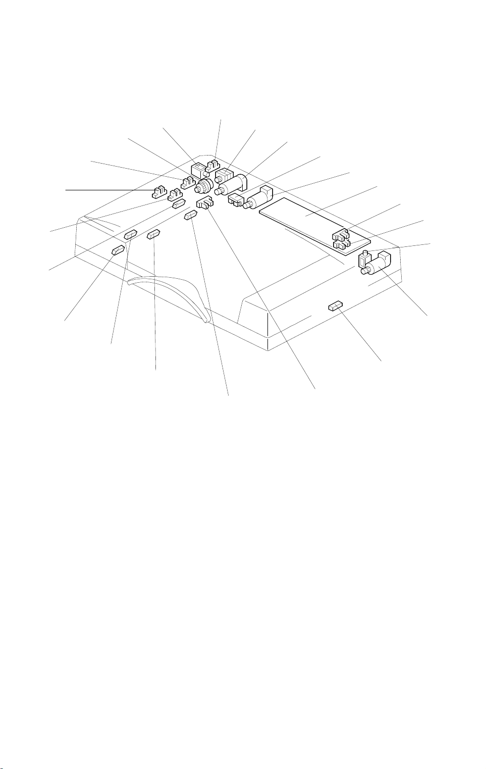
2.2 ELECTRICAL COMPONENT LAYOUT
18
17
19
16
20
15
21
14
22
1
13
2
3
4
5
6
7
8
9
10
11
12
1. Feed-in Cover Open Sensor
2. Friction Belt Motor
3. Feed-in Motor
4. Indicator Panel Lamps
5. Belt Drive Motor
6. DF Main Board
7. DF Position Sensor
8. APS Start Sensor
9. Inverter Solenoid
10. Feed-out Motor
11. Feed-out Sensor
A610V501.wmf
12. Pulse Count Sensor
13. Registration-2 Sensor
14. Original Width-1 Sensor
15. Original Width-2 Sensor
16. Original Width-3 Sensor
17. Registration-1 Sensor
18. Original Set Sensor
19. Original Feed Sensor
20. Friction Belt Turn Sensor
21. Feed-in Clutch
22. Stopper Solenoid
4

10 May 1996 ELECTRICAL COMPONENT DESCRIPTION
3. ELECTRICAL COMPONENT DESCRIPTION
Refer to the electrical component layout on the reverse side of the
point-to-point diagram for symbols and index numbers.
Symbol Name Function Index No.
Motors
M1 Friction Belt Drives the friction belt. 2
M2
M3 Belt Drive Drives the transport belt. 5
M4
Sensors
S1
S2
S3
S4
S5
S6
S7 Original Width- 1 Detects the original width. 14
S8 Original Width- 2 Detects the original width. 15
S9 Original Width- 3 Detects the original width. 16
S10
S11
S12
S13
Feed-in Drives the feed-in system (pick -u p, feed,
pull-out rollers)
Feed-out Drives the feed-out and the inverte r
system.
Feed-in Cover Open Detects whether or not the feed-in cover is
open.
DF Position Informs the CPU whether the DJF is in the
up or down position.
APS Start Informs the CPU when the DJF is being
closed so that the or i gi nal size sensor s in
the main body ca n check the original si ze
(in plat en mode).
Feed-out Checks for orig i nal misfeeds and set s
original stop timing when in auto- reverse
mode.
Pulse Count Counts the pulses generated by the pulse
generator disc t o det er mine the origi nal
length.
Registration -2 Detects the leadi ng edge of the original to
turn off the feed-i n cl utch and to chang e
the feed-in motor speed. Also detect s th e
original length.
Registration -1 Detects the original length and ori gi nal jam
by detecting the trailing edge of the
original.
Original Set Detects if originals have been placed on
the feed table.
Original Feed Detects if the originals have reached the
feed roller or not .
Friction Belt Turn Counts the pulses generated by the p ul se
generator disk t o m oni t or the friction bel t
motor.
3
10
1
7
8
11
12
13
17
18
19
20
Feeder
Dual Job
5

ELECTRICAL COMPONENT DESCRIPTION 10 May 1996
Symbol Name Function Index No.
Solenoids
SOL1
SOL2
PCBs
PCB1 DF Main Board Controls all DJF functions. 6
Magnetic Clutch
CL1
Indica t or Lamps
L1
Inverter Inverts the original when copying
two-sided originals.
Stopper Lifts the original stopper and lowers the
press roller to fe ed t he set of originals to
the feed roller.
Feed-in Transmits the feed-in motor drive to the
pick-up, feed, and pull-out rollers.
Ready Informs the oper at or that the DJF is in th e
down position.
Auto Informs the operator that the auto feed
mode is available.
9
22
21
4
6
10 May 1996 ORIGINAL PICK-UP MECHANISM
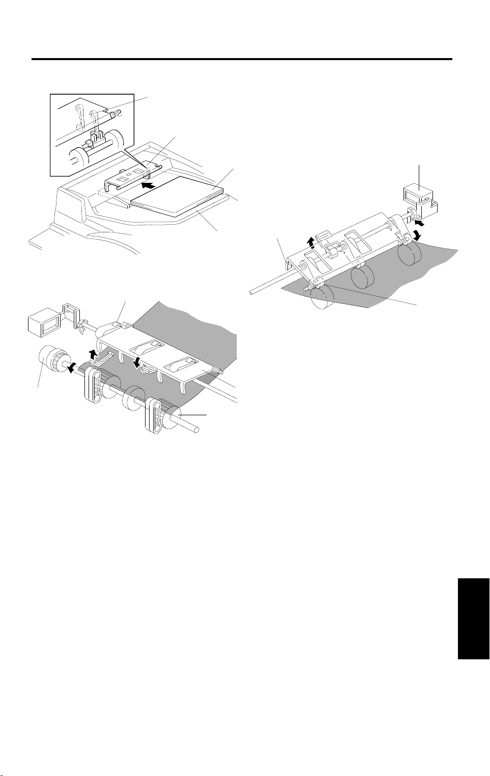
4. ORIGINAL PICK-UP MECHANISM
[G]
[J]
[D]
[C]
A610D500.wmf
[B]
[E]
[A]
[C]
[F]
A610D501.wmf
[I]
[H]
A610D502.wmf
When an original [A] is placed on the original table [B], the leading edge is
stopped by the stopper [C], and the feeler [D] is pushed out of the original set
sensor. The Insert Original indicator light goes out and the DJF informs the
copier’s CPU that the originals have been placed on the original table.
When the Start key is pressed, the copier’s CPU sends the feed-in signal to
the DJF. On receipt of this signal, the stopper solenoid [E] activates to raise
the stopper, which allows the originals to be fed in, and to lower the press
rollers [F] to press the originals against the pick-up rollers, as shown.
The feed-in clutch [G] also activates when the DJF receives the feed-in
signal. 200 ms after the feed-in clutch activates, the feed-in motor feeds all
originals to the feed roller [H].
When the originals reach the feed roller, the stopper solenoid de-activates to
lower the original stopper [I] and to lift up the press rollers [J].
Feeder
Dual Job
7
SEPARATION AND FEED MECHANISM 10 May 1996
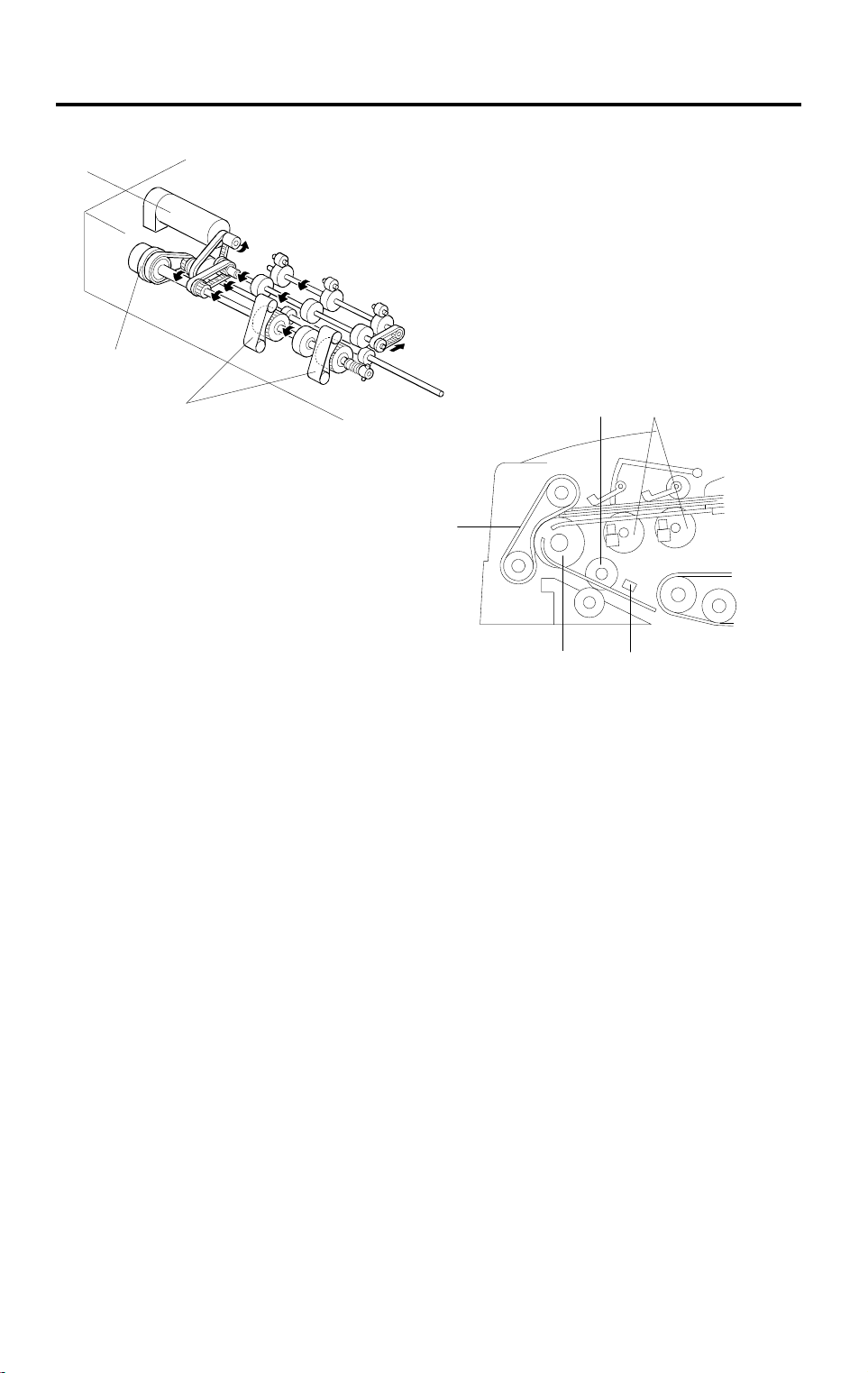
5. SEPARATION AND FEED MECHANISM
[A]
[E]
[F]
A610D505.wmf
[D] [B]
[F]
[C]
[G]
A610D504.wmf
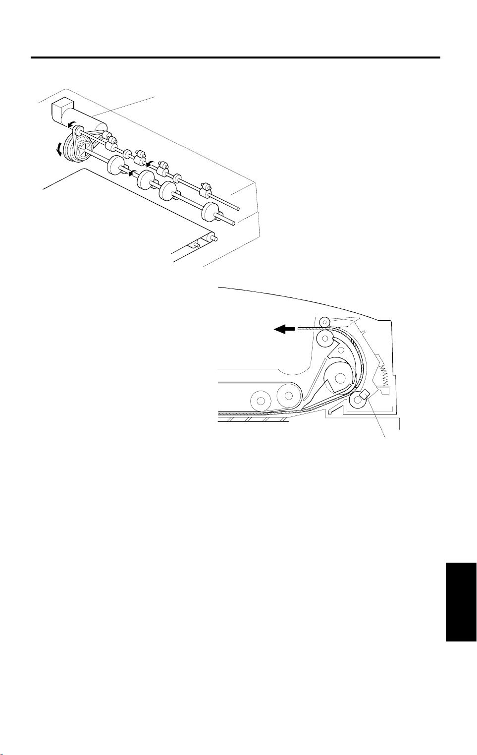
Drive from the feed-in motor [A] is transmitted to the pick-up [B], feed [C], and
pull-out rollers [D], through the feed-in clutch [E], as shown. The feed roller
and the friction belts [F] are used to feed and separate the originals.
Original feed starts when the feed roller starts turning to advance the bottom
original of the stack. The feed roller moves the original past the separation
belt because the driving force of the feed roller is greater than the resistance
of the friction belt. The friction belt prevents multiple feeds because the
resistance of the friction belt is greater than the friction between original
sheets. At this time, the feed-in motor rotates slowly to ensure proper feed
and separation of the original.
When the leading edge of the original activates registration sensor-2 [G], the
feed-in clutch turns off and the motor rotates more quickly. To reduce
mechanical load, only the pull-out rollers are driven to feed the original to the
exposure glass.
To prepare the next original, it is separated in the same manner as explained
above, and stopped when the leading edge is detected by the registration
sensor-2 [G]. When it is time to feed this sheet to the exposure glass, the
feed-in motor rotates at high speed.
8
10 May 1996 FRICTION BELT DRIVE MECHANISM
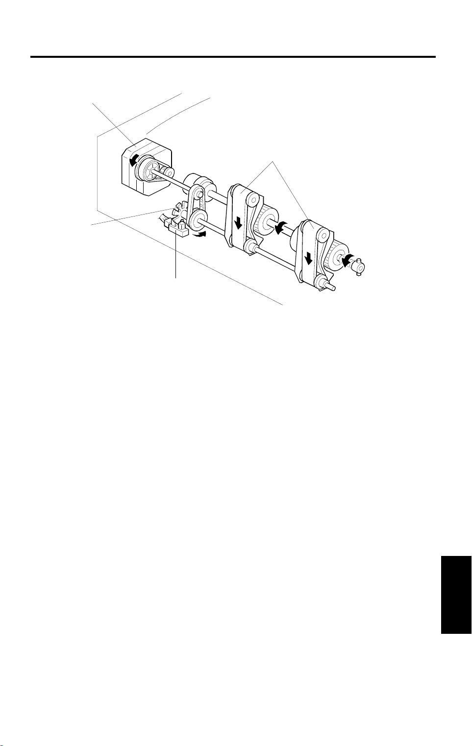
6. FRICTION BELT DRIVE MECHANISM
[B]
[A]
[D]
[C]
A610D506.wmf
The friction belts [A] are driven by the friction belt drive motor [B] through
timing belts, as shown.
When the Start key is pressed, the friction belts are not rotated (the motor is
electrically ON but the motor does not turn as the voltage is too low; see the
timing chart in section 13.1). As the leading edge of the original activates the
registration sensor-2, the friction belts rotate in the reverse direction to
reverse out the next original from in between the friction belts and feed
rollers. This results in less of a chance for originals to be damaged or
become dirty. Also, the area of the friction belt that contacts the feed roller or
the original changes, to prevent multiple feeding.
The friction belt turn sensor [C] counts the pulses generated by the pulse
generator disk [D] on the friction belt shaft. The sensor detects friction belt
motor error conditions.
Feeder
Dual Job
9
ORIGINAL SIZE DETECTION 10 May 1996
7. ORIGINAL SIZE DETECTION
[D]
[E]
[A]
[C]
[F]
[G]
A610D507.wmf
[B]
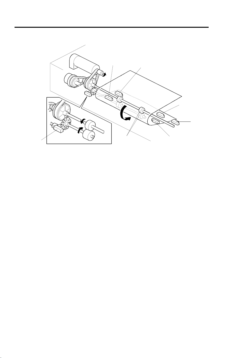
The DJF detects original width through the on/off combination of the three
original width sensors-1 [A], -2 [B], -3 [C]. It also detects the original length
with the registration sensors-1 [D], -2 [E] and the pulse count sensor [F].
The DJF CPU counts the pulses between registration sensor-2 [E] on timing,
and registration sensor-1 [D] off timing. Based on this pulse count, the CPU
determines the original length.
The reasons for using two registration sensors are:
1) Registration sensor-2 [E] is used to stop the pre-fed original, which
waits until the previous original is fed out. For precise control, the
original stop position must be after the pull-out rollers [G]. Therefore,
registration sensor-2 is placed after the pull-out rollers.
2) Registration sensor-1 [D] checks the trailing edge of the original. This
check is used to place the original in the correct position on the
exposure glass. Because this is a fast feeding mechanism, some
distance is required between the sensor and the original scale. If
sensor-2 was used to detect the stop timing, there would not be
enough time to stop the original at the correct place. Therefore,
registration sensor-1 is used for this; it is placed 34.9 mm before
sensor-2.
(The diagram at the start of section 8-1 shows the position of the
sensors with respect to the rollers.)
10
10 May 1996 ORIGINAL SIZE DETECTION
Width Sensor
123
or
: Paper Present
: No Paper
: Sideways
S
: Lengthwise
L
Width Sensor Position
Upper: Original Size
Lower: Threshold Level for Each Size (Pulse Count)
Original Alignment
ABC
Width Sensor 1: A = 210 mm
A4S A3
231 mm
(78)
B5 S LTS B4 11" x 15" A3
201 mm
(68)
B6S A5S B6 L A5 L B5 L
143 mm
(44)
236 mm
(80)
166 mm
(54)
377 mm
(136)
201 mm
(68)
231 mm
(78)
399 mm
(145)
271 mm
(95)
294 mm
(103)
316 mm
(115)
A3B4A4 LLT L
387 mm
(140)
A610D508.wmf
Width Sensor 2: B = 235 mm
Width Sensor 3: C = 284 mm
A610D509.wmf
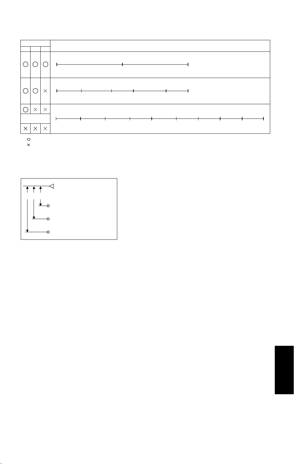
The original size is determined by the combination of the detected original
width and length as shown above. Note that when only width sensor 1 detect
that paper is preset, or if all width sensors are off, the original size is detected
only by the pulse count sensor data.
Feeder
Dual Job
11
TRANSPORT MECHANISM 10 May 1996
8. TRANSPORT MECHANISM
8.1 BASIC OPERATION
[E]
[D]
A610D511.wmf
[A]
[B]
[C]
A610D512.wmf
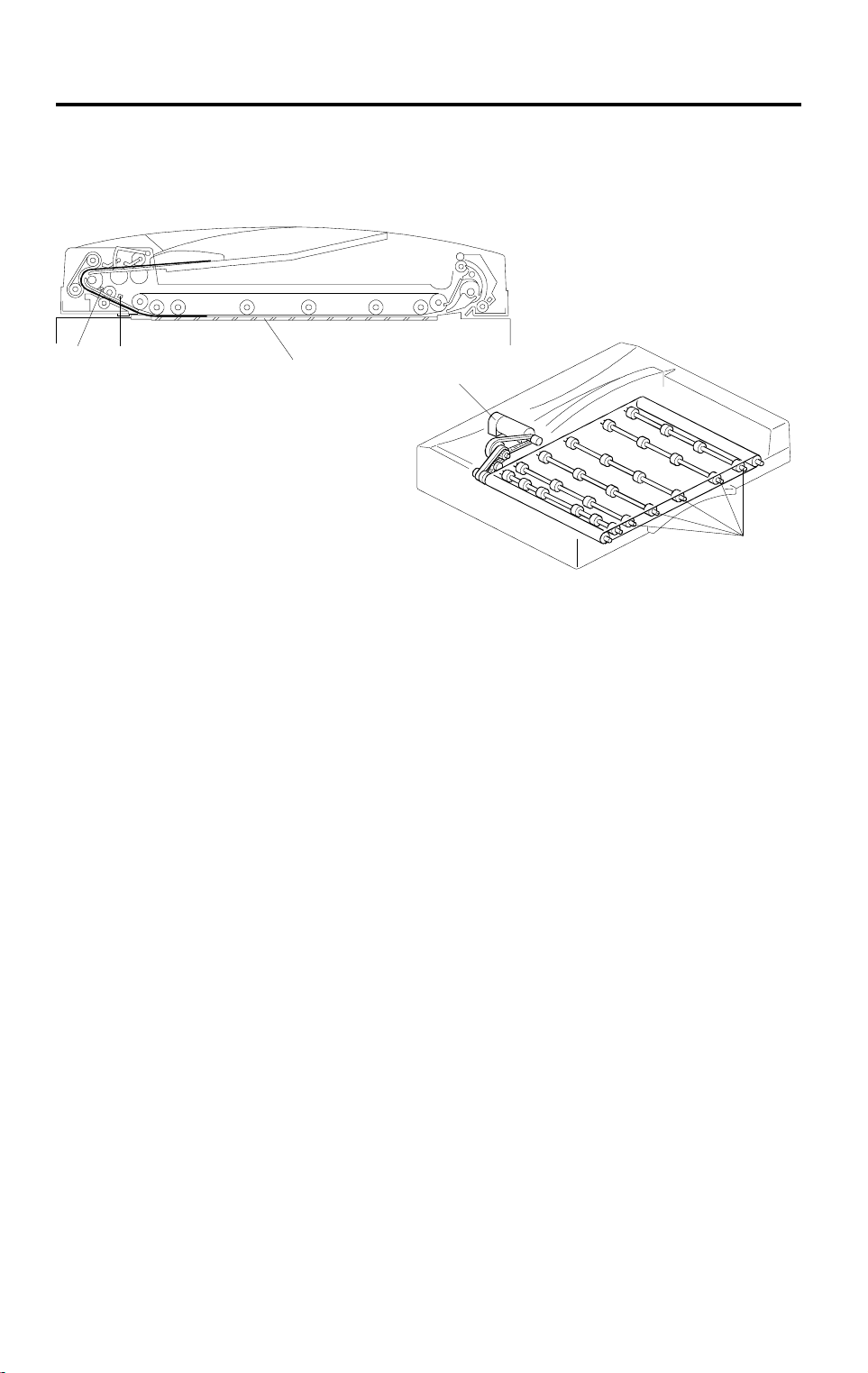
The transport belt [A] is driven by an independent motor called the belt drive
motor [B]. The belt drive motor starts rotating soon after the copier sends an
original feed-in signal. Inside the transport belt are five pressure roller shafts
[C], which achieve the proper amount of pressure between the belt and the
original.
When the leading edge of the original reaches the exposure glass, the
original is transported by the transport belt (the belt drive motor turns on 200
ms after the start key is pressed).
When the trailing edge of the original passes through registration sensor-1
[D], the feed-in motor turns off. When the trailing edge of the original passes
through registration sensor-2 [E], the belt drive motor gradually decreases its
speed to stop the original at the proper place on the exposure glass.
100 ms after the belt drive motor turns off, the feed-in motor turns on until the
next original activates registration sensor-2 [E], the next original waits until
the first original copy job is complete. This operation reduces the original feed
in time.
When the scanner reaches the return position, the copier’s CPU sends the
feed-out and feed-in signals to the DJF CPU, and the feed-in motor is
activated again to change the original.
If the original is smaller than A4 sideways, the original just copied is
transported to the right side of the exposure glass then waits until the next
original copy job is completed. Then the previous original is delivered. This
operation also reduces the original feed-in time.
12

10 May 1996 TRANSPORT MECHANISM
Left Scale
Rear Scale
5.0 mm
Original
A610D513.wmf
Since the copier’s original alignment position is at the left rear corner (not in
the center), the originals fed from the DJF must also be at this position. But if
the original was to be fed along the rear scale, original skews, jams or
wrinkling, may occur.
To prevent such problems, the original transfer position is set to 5.0 mm
away from the rear scale as shown. The correction for this 5.0 mm gap is
compensated for by the base copier’s optics unit.
13
Feeder
Dual Job
TRANSPORT MECHANISM 10 May 1996
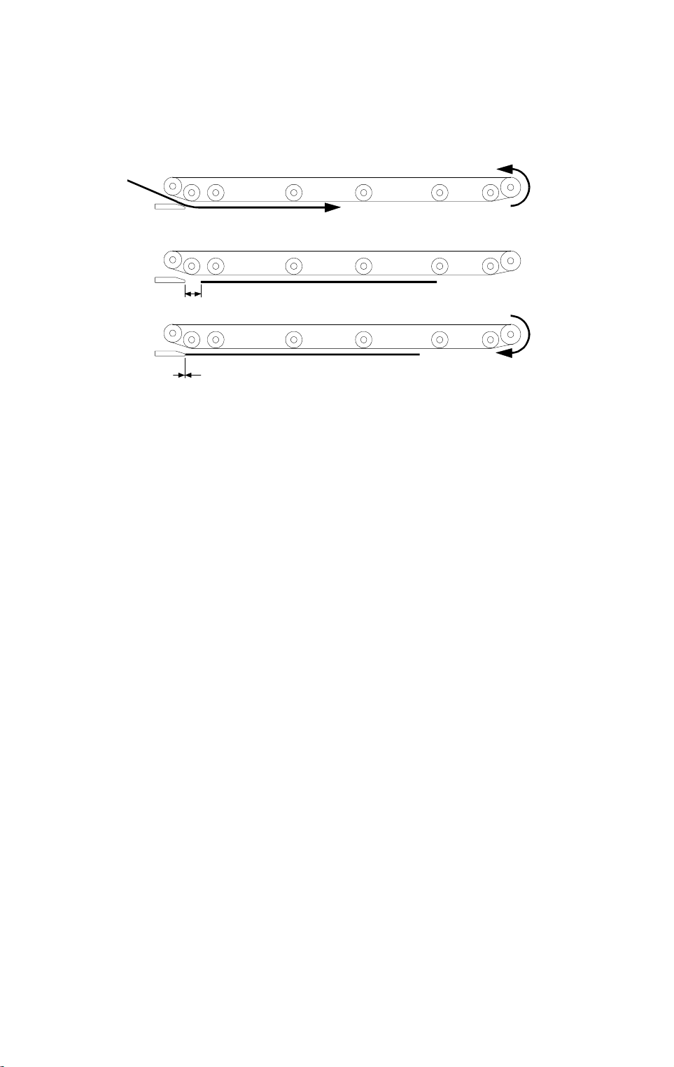
8.2 THIN/THICK ORIGINAL MODES
Fig. 1
10±2 mm
25 mm
Fig. 2
Fig. 3
A610D514.wmf
This document feeder has two different ways of stopping originals on the
exposure glass at the correct position. They are thin original mode and thick
original mode. The user can select the desired settings to match the type of
original being used.
1. Thick Original Mode
When thick original mode is selected, the belt drive motor remains
energized to carry the original approximately 10 mm past the left scale
(Figures 1 and 2). Then, the belt drive motor pauses and reverses to feed
the original back against the original scale for about 25 mm (Fig. 3). This
forces the original against the left scale and thus aligns the trailing edge
of the original with the scale.
Thick original mode is selected at the factory.
2. Thin Original Mode
To protect originals from being damaged by the movements of the
transfer belt, thin original mode can be selected. The original is stopped
at the correct position on the exposure glass based on an encoder pulse
count. The belt drive motor stops shortly after the original trailing edge
passes registration sensor-2. (Exact timing depends on registration
adjustment.)
The feed amount for both modes can be adjusted.
For more details, refer to the "Replacement and Adjustment" section.
14
10 May 1996 ORIGINAL FEED-OUT MECHANISM
9. ORIGINAL FEED-OUT MECHANISM
A610D516.wmf
[A]
[B]
A610D515.wmf
When the scanner reaches the return position, the copier’s CPU sends the
feed-out signal to the DJF CPU.
When the DJF receives the feed-out signal, the belt drive and feed-out
motors [A] turn on.
The feed-out sensor [B] installed in the feed-out section counts the number of
pulses to calculate how long the feed-out motor must stay on to feed the
original out of the machine properly. Also, the motor rotates at low speed for
the last 50 mm of the detected trailing edge to improve stacking efficiency.
15
Feeder
Dual Job
TRANSPORT BELT LEVELING MECHANISM 10 May 1996
10. TRANSPORT BELT LEVELING MECHANISM
[B]
[A]
[F]
[D]
A610D525.wmf
[F]
[E]
[C]
A610D526.wmf
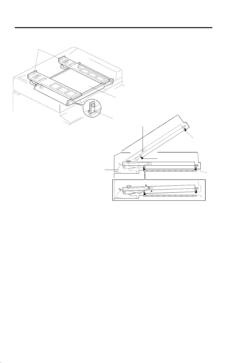
The transport belt [A] and the two support arms [B] are formed as one unit,
(made of aluminum). This results in a more flexible structure than the
monocoque type (in which the cover carries all of the stress), and the gap
between the transport belt and the original can easily be kept precise during
belt transport.
On the support arm linked with the DJF hinge [C], there is a fulcrum [D] to
support the DJF. When the DJF is being closed and the rear stopper [E]
contacts the base copier first, the DJF rotates about the fulcrum, rotates and
the front stopper [F] will also contact the base copier to level the belt with the
exposure glass.
16
10 May 1996 LIFT MECHANISM
11. LIFT MECHANISM
[A]
[C]
[B]
[E]
A610D527.img
➀
➂
➁
➂
➀
➁
A610D528.img
[D]
A610D533.wmf
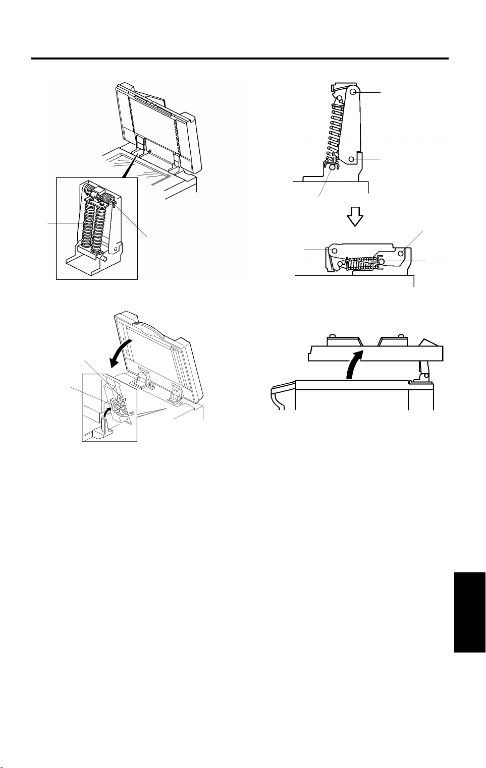
When the DJF is opened, the lift springs [A] provide enough force to ensure
that the DJF does not fall onto the exposure glass. When the DJF is closed,
", "➁", and "➂" are positioned as shown and no upward force is
points "
provided to the DJF.
The position sensor [B] is actuated when the DJF is closed. The copier then
shifts to the document feeder mode. The position sensor also serves as the
reset switch for DJF misfeeds.
After the cover is closed, the APS start sensor [C], which is below the DF
position sensor, informs the base copier CPU that original size sensors in the
main body can check the original size for the platen mode.
When a book or thick original (maximum thickness 60 mm) is copied, the DJF
acts as a cover for the original as shown in the diagram [D]. The position
sensor is turned off during this condition, so the DJF does not function. The
tension of spring [E] returns the DJF to the normal condition after copying a
thick original.
➀
A610D529.img
Feeder
Dual Job
17
SPECIAL FEATURES 10 May 1996
12. SPECIAL FEATURES
12.1 PRESET MODE
[C]
[E]
[B]
[D]
[F]
[A]
A610D510.wmf
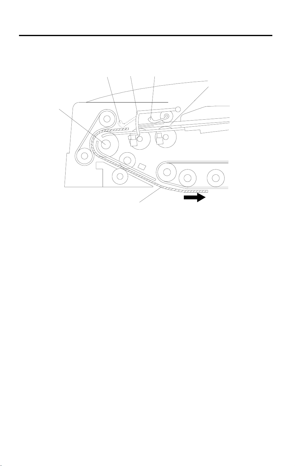
Two sets of originals for independent copy jobs can be set on the original tray
at the same time.
While the first set of originals [A] remains on the original tray, both the original
set sensor feeler [B] and original feed sensor feeler [C] are lifted out of their
sensors. A second set of originals [D] can be placed in the feeder on top of
the first set, as far as the original stopper [E]. In this case, when the first set
of originals are all fed-in, the original set sensor feeler is still lifted out of the
sensor, but the original feed sensor has dropped into the sensor. Therefore,
the copier’s CPU recognizes that the first job is completed.
If the second job is already preset, the second set of originals is automatically
fed to the feed roller [F] and fed one-by-one into the machine in the same
manner as the first set of originals.
18
 Loading...