

Page 1
Technical Bulletin No. RTB-005
[B]
SUBJECT: F400/F410 Dual Job Feeder separation belts
(manual correction)
PREPARED BY: S.MANO
CHECKED BY:
CLASSIFICATION:
Action Required
Troubleshooting
Retrofit Information
The quantity of the separation belt have been changed from two to four.
Reason of the modification:
On the original printed by the laser printer, the toner may not be fused sufficiently and the
image may smeared by the separation belts.
To prevent this, two more separation belts are added to widen the contacting area
between the separation belts and the original so that the separation pressure is not
concentrated to the narrow area.
Revision of service manual
Information only
Other
FROM: Copier Technical Support Group
MODEL: F400/F410
DATE:SEP.15.’93
PAGE: 1 of 3
After this modification, these separation belts are still PM parts and the replacement
interval is 1PM (120k copies) as same as before this modification.
Because of this modification, the illustrations in page 7, 14, 15, 34 and 35 should be
changed. The quantity of the separation belts should be doubled. There is no correction
except illustrations.
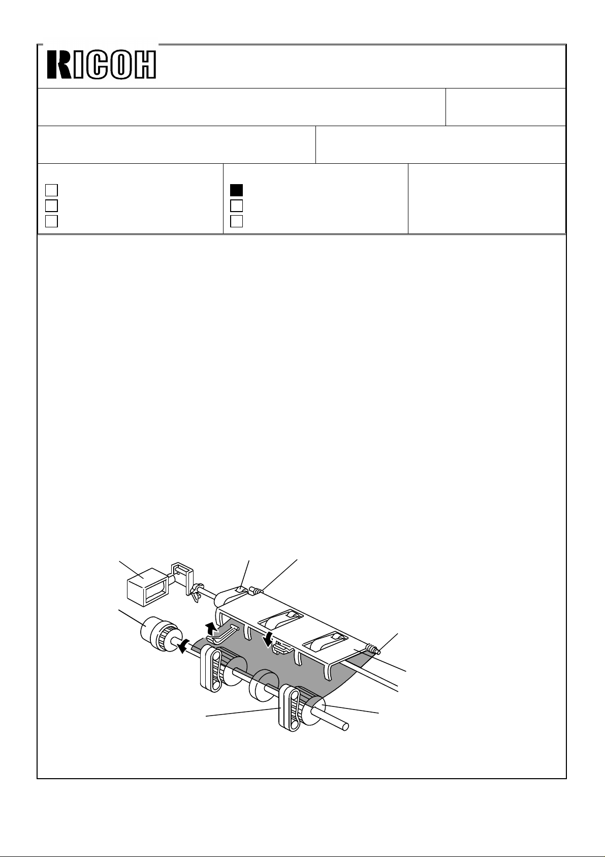
Manual corrections:
Page 7 - upper illustration
[C]
[A]
[E]
[D]
[F]
Page 2

Technical Bulletin No. RTB-005
[B]
[C]
SUBJECT: F400/F410 Dual Job Feeder separation belts
(manual correction)
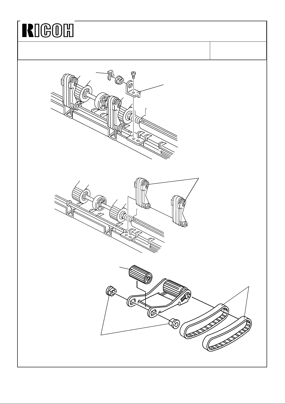
Page 14 lower illustration
[A]
[D]
[E]
Page 15 illustration
DATE:SEP.15.’93
PAGE: 2 of 3
[B]
[C]
[A]
[D]
Page 3
Technical Bulletin No. RTB-005
SUBJECT: F400/F410 Dual Job Feeder separation belts
(manual correction)
Page 34 lower illustration
[E]
[D]
Page 35 illustrations
DATE:SEP.15.’93
PAGE: 3 of 3
[A]
[B]
[C]
[D]
Page 4

Technical Bulletin No. RTB-006
SUBJECT: F400/F410 Troubleshooting DATE:Nov.30, ’93
PAGE: 7 of 10
9. DJF Original Skew
< Phenomenon>
If original skews occur as illustrated even if the DJF height is correctly adjusted, perform
the following adjustment.
Rear
Left scale
< Possible cause>
This skew is caused because the transport belt is faster than the feed-in motor speed,
even if both motor speeds are within the specification.
< Countermeasure>
1. Feed-in motor speed adjustment
Adjust the feed-in motor speed so that the motor speed becomes higher (within
specification).
1–1 Turn DIP SW 101-1, 2, 4 to "ON".
1–2 Turn DIP SW 102-1 to "ON".
1–3 Turn VR 103 towards "H" to turn LED 101 (Red) on.
1–4 Turn VR 103 towards "L" to turn LED 102 (Green) on.
2. Transport belt motor speed adjustment
Adjust the transport belt motor speed so that the motor speed becomes lower (within
specification).
1–1 Turn DIP SW 101-1, 2, 4 to "ON".
1–2 Turn DIP SW 102-2 to "ON".
1–3 Turn VR 104 towards "L" to turn LED 103 (Red) on.
1–4 Turn VR 104 towards "H" to turn LED 102 (Green) on.
Page 5
Technical Bulletin No. RTB-008
SUBJECT: DJF Multiple feeding DATE:Nov.30, ’93
PAGE: 1 of 2
PREPARED BY: S. MANO
CHECKED BY:
CLASSIFICATION:
Action Required
Troubleshooting
Retrofit Information
< Phenomenon >
Original multiple feeding occurs when there is high friction between the originals. This
tends to occur especially when the originals have staple holes, or computer forms with
rough edg es.
< Possible cause >
[C]
Revision of service manual
Information only
Other
FROM: Copier Technical Support Group
MODEL: F400/F410
[D]
[A]
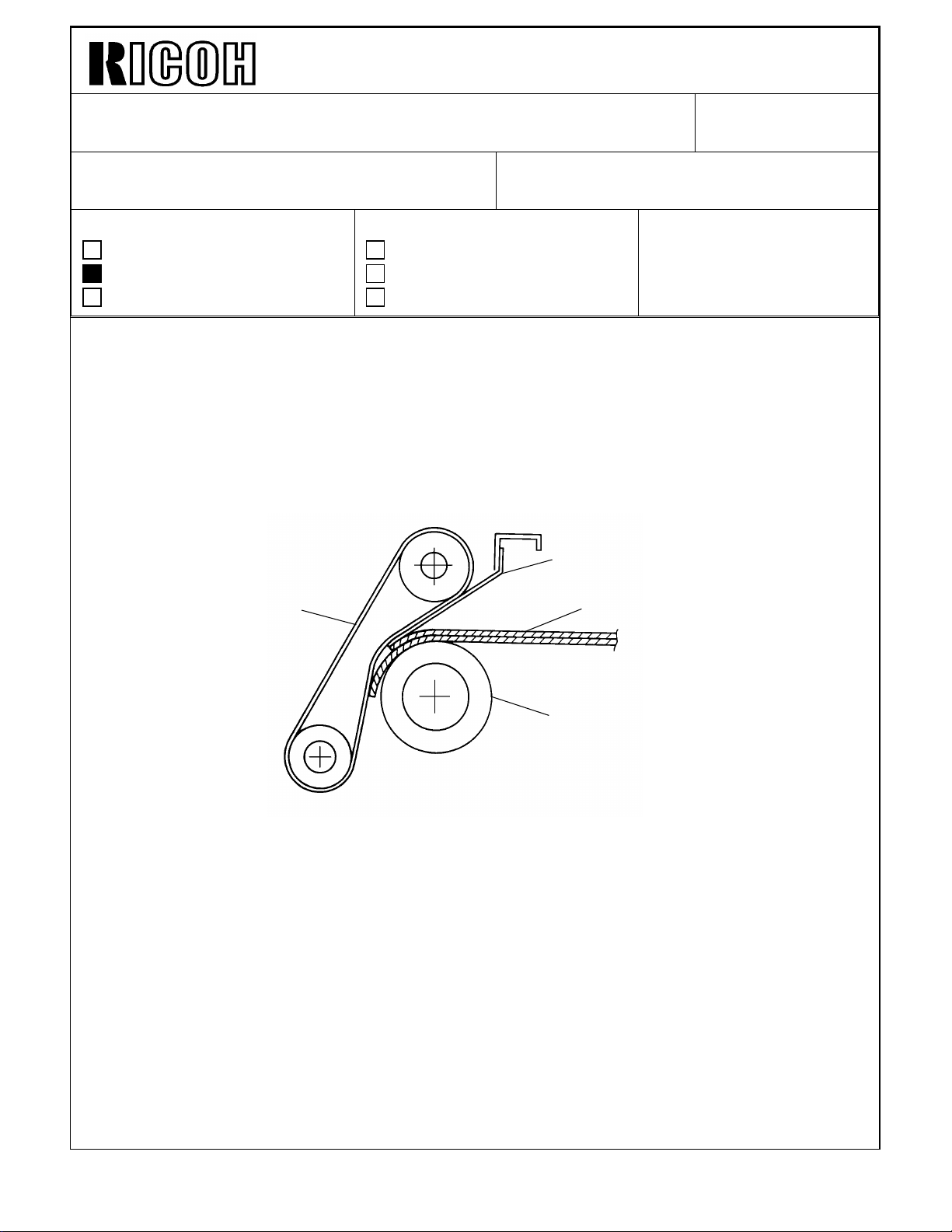
[B]
When the originals [A] comes between the feed rollers [B] and the separation belts [C],
they meet the mylar [D] between them and the separation belts. This guide mylar
transports the originals smoothly to the gap between the feed rollers and the separation
belts. The mylar length determines the original separation force. If the mylar is longer, the
area where the originals touch the separation belt becomes narrower, therefore the
separation force become weaker. If the mylar is shorter, the separation force becomes
stronger. (If it is too short, too much separation force stops original feed)
As a result of our investigation, we found that making the mylar 2mm shorter is the best
condition (higher separation ability without feeding error).
Page 6
Technical Bulletin No. RTB-008
SUBJECT: DJF Multiple feeding DATE:Nov.30, ’93
PAGE: 2 of 2
< Countermeasure >
Replace the original guide mylars (2 mylars per machine). New part is the assembled part
of the mylar and the bracket. New part number is A3761254.
For the cut-in serial number, please refer to the modification bulletin which will be issued
soon.
Guide mylar ass’y : Part number A3761254
Page 7
Technical Bulletin No. RTB-009
SUBJECT: Installation procedure DATE:Nov.30, ’93
PAGE: 2 of 3
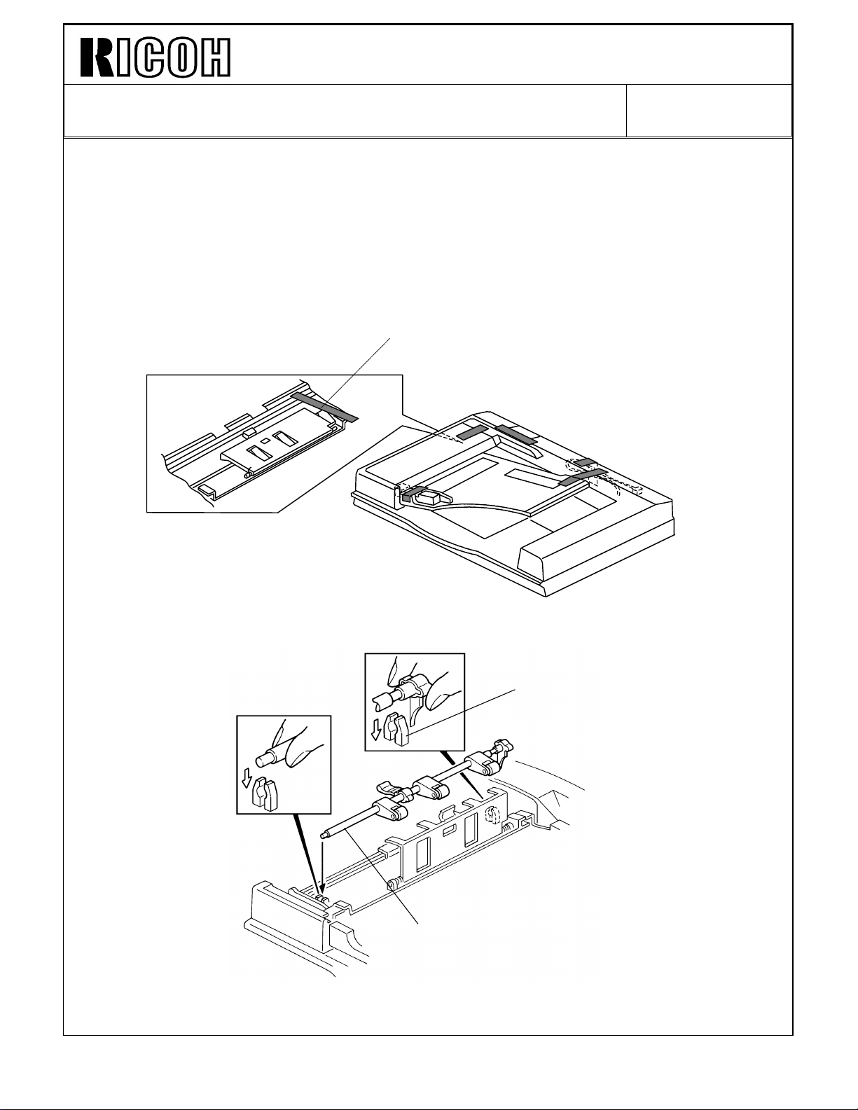
3. Caution for DJF shipping tape removal (dual job feeder service manual - installation
procedure page, 24)
When removing the tape [B] fixing the original press roller shaft [C], be careful to confirm
that the shaft is correctly in the holder [D]. It is possible that the shipping tape adheres
strongly to the shaft. The shaft migit be pulled out from the holder when the tape is
removed.
If the shaft is out of position, the original will not feed.
[B]
[C]
[D]
Page 8
Technical Bulletin No. RTB-010
SUBJECT: DJF feed roller assembly replacement DATE:Nov.30, ’93
PAGE: 1 of 3
PREPARED BY: S.MANO
CHECKED BY:
CLASSIFICATION:
Action Required
Troubleshooting
Retrofit Information
1. Manual correction
In the feed roller replacement procedure (page 32 to 33), there are steps asking to remove
the original table and original guide. Actually, this procedure is not necessary. Please skip
steps 2, 3, 4, and 5. You can directly access the feed roller.
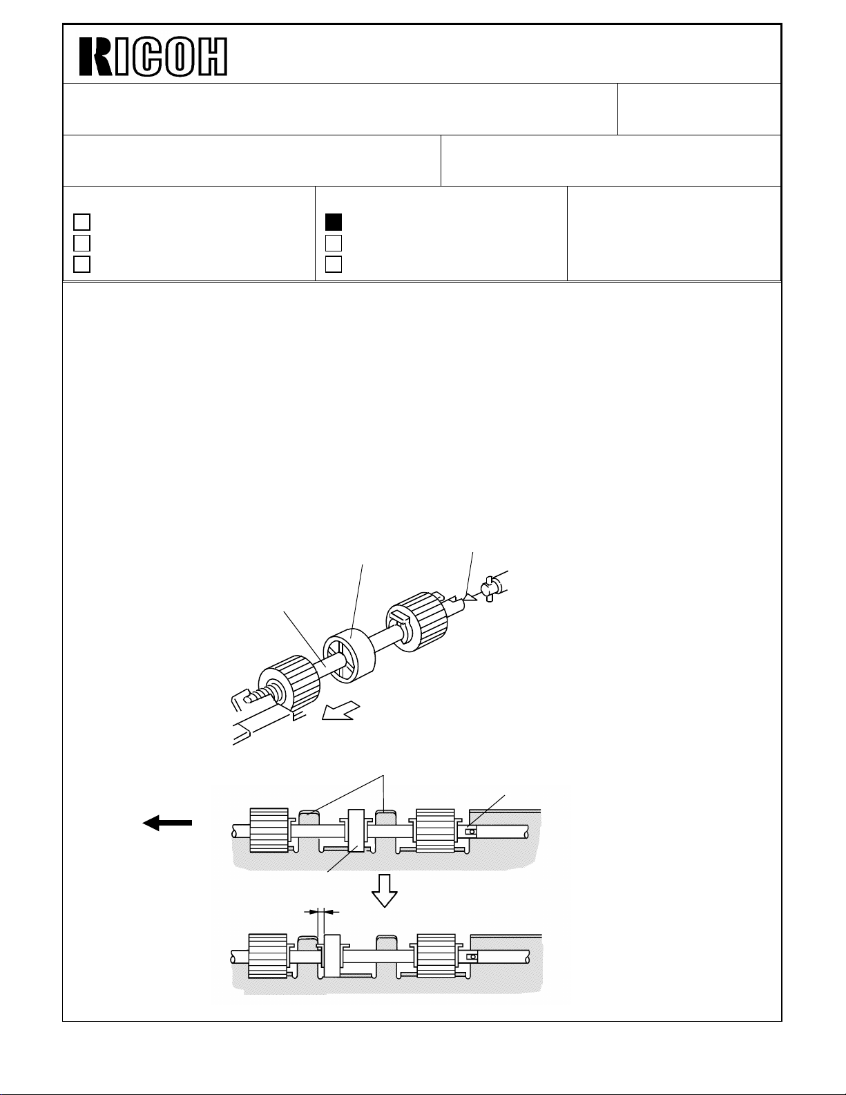
2. Procedure change due to modification.
In the domestic market, we have experienced that the customer took off the feed roller
assembly [A] when removing a jammed original. When the jammed original is pulled to the
front, the feed rollers are pulled to the front and the joint part [B] comes out from the drive
shaft. To prevent this, The middle roller [C] position has been changed (to the rear) as
shown below.
Revision of service manual
Information only
Other
[C]
FROM: Copier Technical Support Group
MODEL: F400/F410
[B]
Front
[A]
Guide Plate
[B]
Old
[C]
New
Page 9

Technical Bulletin No. RTB-010
SUBJECT: DJF feed roller assembly replacement DATE:Nov.30, ’93
PAGE: 2 of 3
Before the modification, the middle roller could be shifted to the front when the feed roller
was pulled to the front. After the modification, when the feed roller is pulled to the front,
the middle roller hits the guide plate and it cannot be moved to the front. This prevents the
joint part from being separated by mistake.
To replace the feed roller assembly, the following procedure is necessary before
performing step 6 (slide the feed roller assembly to the front, then remove it).
* Remove the guide mylars
* Remove the snap ring.
* Hold the feed roller.
After the modification, procedure "14.2 feed roller replacement" is changed as shown in
next page.
Page 10

Technical Bulletin No. RTB-010
SUBJECT: DJF feed roller assembly replacement DATE:Nov.30, ’93
PAGE: 3 of 3
[B]
[A]
Rear
[E]
[F]
[C]
1. Turn off the main switch then open the feed cover [A].
2. Remove the guide mylars [B] ( 1 screw each ).
3. Remove the snap ring [C].
4. Slide the roller [D] to the rear.
[D]
Front
5. Hold the feed roller [E] then slide the shaft to the front, then remove the feed roller
assembly as shown.
6. Remove the four snap rings [F], then remove the feed rollers.
7. Install the new feed rollers, then re-assemble the machine.
Page 11

Technical Bulletin No. RTB-016
SUBJECT: DJF VERTICAL REGISTRATION ADJUSTMENT FOR TWO
SIDED ORIGINAL MODE
PREPARED BY: S. MANO
CHECKED BY:
CLASSIFICATION:
Action Required
Troubleshooting
Retrofit Information
Dual job feeders with the following serial numbers have the possibility that the vertical
registration for two sided original mode is improper due to insufficiant inspection during
production.
Machine Code From To
A376-15 first production 4123110190
A376-17 A3383100001 A338310674
A376-22 5323100001 5323110149
A376-26 3D81030001 3D81130040
A376-27 A3383100921 A3383111103
Revision of service manual
Information only
Other
FROM: Copier Technical Support Section
MODEL:
F400/F410
DUAL JOB FEEDER
A376-10 No machine
DATE:Jan. 31, ’93
PAGE: 1 of 3
If necessary, please adjust the vertical registration (refer to page 46 of the DJF service
manual).
If the vertical registration adjustment cannot be carried out using the procedure on page 46
of the DJF service manual (by using SP adjustment mode), return the SP adjustment data
to "00".
Then adjust the vertical registration by turning VR102 on the DJF main board. The VR102
adjustment has a wider adjustable range than SP adjustment mode (adjustable range by
SP adjustment: -7.5 mm ∼ +7.5 mm, 0.5mm/step).
Page 12

Technical Bulletin No. RTB-016
[B]
VR102
SUBJECT: DJF VERTICAL REGISTRATION ADJUSTMENT FOR TWO
SIDED ORIGINAL MODE
Two Sided Original Mode
[A]
10 ± 2
[C]
DATE:Jan. 31, ’93
PAGE: 2 of 3
1. Remove the copier’s left scale [A] (2 screws).
2. Remove the small cover at the rear side on the upper DJF cover then turn on DIP SW
101-2, 101- 4, and 102- 1.
3. Set a sheet of A4 / 8 1/2" x 11" (53 ∼ 80 g/m2 / 14 ∼ 22 lb) paper sideways on the
original table.
4. Push SW 101 [B].
5. After the original stops on the exposure glass, gently raise the DJF (so that the original
does not move).
6. Confirm that the gap between the trailing edge of the paper and the left edge [C] of the
original rear scale is 10 ± 2 mm.
7. If the gap is not within specification, adjust the registration by using the copier SP mode
1
( SP Adjustment - PAGE 6).
NOTE: 1. Before setting the original on the original table again, open and close the
feed unit cover [C].
2. After completing the adjustment, return the DIP switches to their original
condition.
Page 13

Technical Bulletin No. RTB-016
SUBJECT: DJF VERTICAL REGISTRATION ADJUSTMENT FOR TWO
SIDED ORIGINAL MODE
8. If the registration cannot be adjusted even though the SP data is changed to the
maximum value, return the data to "00".
9. Adjust the vertical adjustment by turning VR102 on the DJF main board.
DATE:Jan. 31, ’93
PAGE: 3 of 3
Page 14

Technical Bulletin No. RTB-017
SUBJECT: MANUAL CORRECTIONS DATE: Jan. 31,’94
PAGE: 9 of 13
Page 6-19 1.15
• Incorrect
1.15 DUAL JOB FEEDER
Definition: [Level:B]
Encoder pulse is not detected by the DJF main board......
Possible causes
DJF feed motor defective
DJF transport motor defective
DJF feed out motor defective
DJF inverter motor defective
• Correct
1.15 DUAL JOB FEEDER/RECIRCULATING DOCUMENT HANDLER
Definition: [Level:B]
Encoder pulse is not detected by the DJF/RDH main board......
Possible causes
DJF/RDH feed motor defective
DJF/RDH transport motor defective
DJF/RDH feed out motor defective
RDH inverter motor defective
Page 11 of DJF Illustration
• Incorrect
In Fig.2, the left paper is expressed by a dotted line and the right paper is expressed by
solid line.
• Correct
In Fig.2, the left paper position is shown
by a solid line and the right paper position
is shown by a dotted line as shown.
Page 15

Technical Bulletin No. RTB-017
SUBJECT: MANUAL CORRECTIONS DATE: Jan. 31,’94
PAGE: 10 of 13
Page 12 of DJF 3rd line of [Figure 3] explanation
• Incorrect
A few pulses (0 ∼ 14 pulses: depends on the SP mode adjustment) ....
• Correct
A few pulses (0 ∼ 14 pulses: depends on the DIP switch adjustment) ....
Page 27 of DJF 3rd line of upper NOTE and Illustration
• Incorrect
..... loosen four truss head screws [D], and tighten.
[D]
• Correct
..... remove the cover [D] (4 screws), and loosen then tighten 4 screws [E].
[D]
[E]
Page 16

Technical Bulletin No. RTB-017
[C]
SUBJECT: MANUAL CORRECTIONS DATE: Jan. 31,’94
PAGE:11 of 13
Page 43 of DJF Illustration
• Incorrect
• Correct
[D]
[C]
Page 46 of DJF Step 6
• Incorrect
6. Confirm that the gap between the trailing edge of the paper and the left edge [C] of
the original rear scale is 10 ± 2mm.
• Correct
6. Confirm that the gap between the trailing edge of the paper and the right edge of the
original rear scale is 10 ± 2mm.
[E]
[E]
[D]
Page 17

Technical Bulletin No. RTB-020
SUBJECT: Manual Correction DATE:
February. 15, 1994
PAGE: 1 of 2
PREPARED BY: S. Mano
CHECKED BY:
CLASSIFICATION:
Action Required
Troubleshooting
Retrofit Information
Revision of service manual
Information only
Other
FROM: Copier Technical Support Section
MANUAL CORRECTION
Page 4-59 DUAL JOB FEEDER Preventive Maintenance Schedule
Incorrect
EM 120K 240K 360K NOTE
DUAL JOB FEEDER (for originals)
Transport Belt
Pick-up Roller
Feed Roller
Separation Belts
CRRR
CCCC
CRRR
CRRR
Belt cleaner. Replace if
necessary.
Alcohol. Replace if
necessary.
Alcohol. Replace if
necessary.
Alcohol. Replace if
necessary.
MODEL: F400 DJF
Correct
DUAL JOB FEEDER (for copies)
Transport Belt
Pick-up Roller
Feed Roller
Separation Belts
EM 120K 240K 360K NOTE
CRRR
CCCC
CRRR
CRRR
Belt cleaner. Replace if
necessary.
Alcohol. Replace if
necessary.
Alcohol. Replace if
necessary.
Alcohol. Replace if
necessary.
Page 18

Technical Bulletin No. RTB-020
SUBJECT: Manual correction DATE:
February 15, 1994
PAGE: 2 of 2
Each parts’s actual estimated life is 48K original feed times.
Since estimated average copies per one original is 2.5, we recommend to replace the
transport belt, separation belts and feed roller at the same time as the copier’s 120K PM.
(48,000 x 2.5 = 120, 000)
Because the F400/F410 series has an SP mode PM counter (indicates the original feed
time since the last PM), you can recognize how many times originals have been fed since
the last PM parts replacement. We recommend utilizing this function to manage the PM
parts replacement interval.
Therefore, if you utilize PM counter for original feed ( 9 PM COUNTER CLEAR PAGE4),
the PM table is as follows:
EM 48K 96K 144K NOTE
DUAL JOB FEEDER (for originals)
Transport Belt
Pick-up Roller
Feed Roller
Separation Belts
CRRR
CCCC
CRRR
CRRR
Belt cleaner. Replace if
necessary.
Alcohol. Replace if
necessary.
Alcohol. Replace if
necessary.
Alcohol. Replace if
necessary.
Concerning the RDH, the copy volume and original feed times are almost the same.
We just recommend to replacing PM parts at the same time as the copier’s 120K PM
(transport belt: replace at every copier’s 240K PM).
Page 19

Technical Bulletin No. RTB-025
[A]
SUBJECT: DJF ORIGINAL DOUBLE FEEDING DATE: Mar. 15 ’94
PAGE: 1 of 2
PREPARED BY: S. MANO
CHECKED BY: S. Hamano
CLASSIFICATION:
Action Required
Troubleshooting
Retrofit Information
Revision of service manual
Information only
Other
FROM: 2nd Technical Support Section
MODEL:DJF for F400
series
Phenomenon
Original double feeding (two originals are fed at a time) tends to occur when the
separation belts [A] become dirty with foreign matter which being transferred from the
original surface.
Cause
When the separation belt surface is covered with foreign matter, the friction between the
original and the separation belt decreases. This reduces the original separation ability.
[A]
Page 20

Technical Bulletin No. RTB-025
SUBJECT: DJF ORIGINAL DOUBLE FEEDING DATE: Mar. 15 ’94
PAGE: 2 of 2
Countermeasure
Clean the separation belt surface with alcohol to recover the separation ability. We
recommend to do this at every customer visit including at the installation to eliminate
further EM calls.
Note: If block original feeding (10~20 sheets of originals are fed at a time) occurs,
replace the original guide mylars [A] to the new parts (A3761254). Please refer to
RTB-008 for the details.
[A]
Page 21

Technical Bulletin No. RTB-033
SUBJECT: Irregular original stack in auto counting mode DATE: April 30, ’94
PAGE: 1 of 2
PREPARED BY: S. MANO
CHECKED BY: S. Hamano
CLASSIFICATION:
Action Required
Troubleshooting
Retrofit Information
<PHENOMENON>
During auto counting mode, the original delivery speed varies. The original stack alignment
become irregular, and in the worst case, the original order changes.
This probleme specially occurs when feeding letter (8 1/2" x 11") sideways originals.
<PHENOMENON>
When the original is delivered in auto counting mode, the original exit motor changes its
speed. Just before the trailing edge of the original passes through the exit roller, its speed
decreases to correct the original stack. Normally the original exit motor changes to the
quicker speed after completely feeding out the original. However, sometimes, the exit
motor returns to the quicker speed before the original trailing edge passes through the exit
roller. In this case, the original is pushed out quickly, resulting in the irregular original stack.
Revision of service manual
Information only
Other
FROM: 2nd Technical Support Section
MODEL: F400 / F410
Page 22

Technical Bulletin No. RTB-033
SUBJECT: Irregular original stack in auto counting mode DATE: April 30, ’94
PAGE: 2 of 2
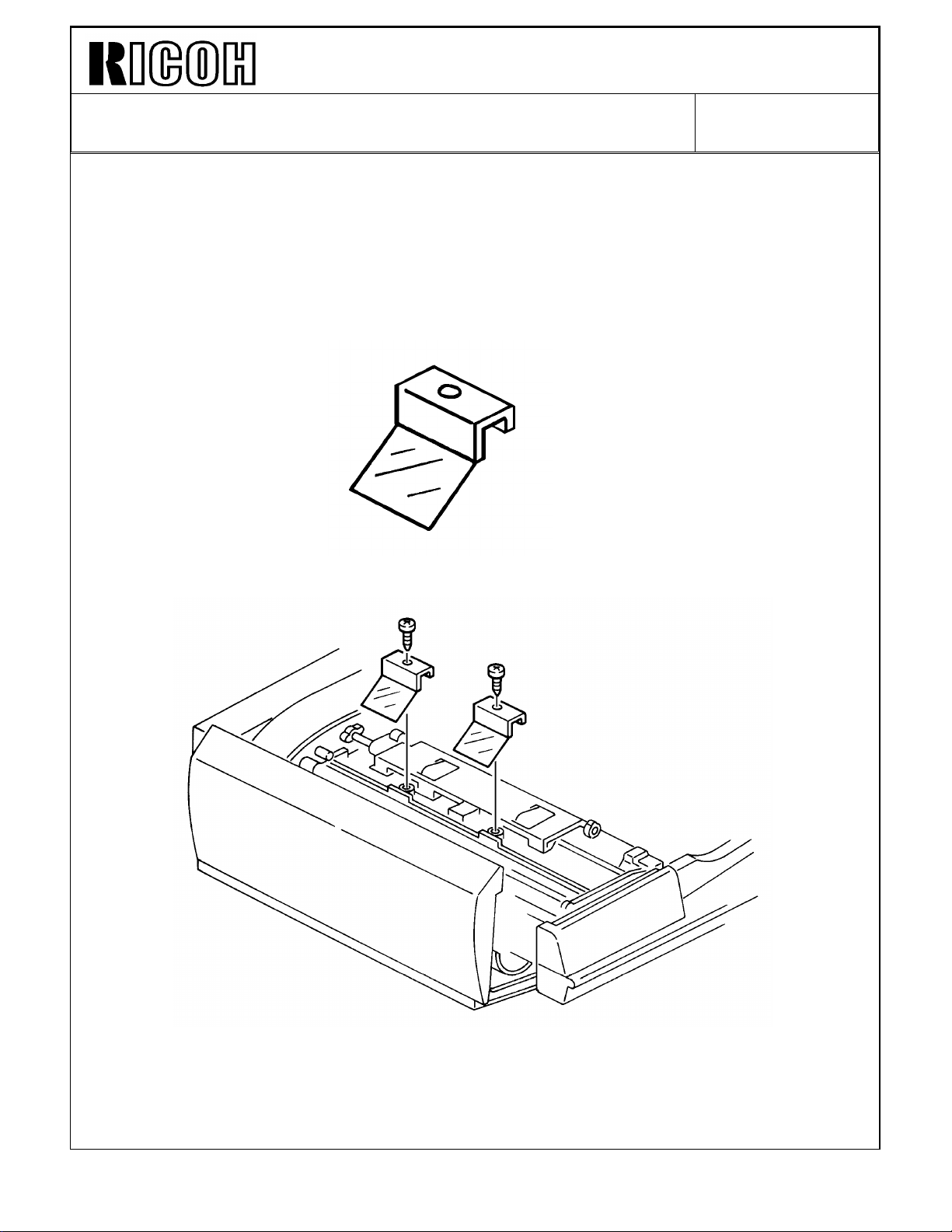
<COUNTERMEASURE>
The original stack guide mylar is added. This mylar is attached to the DJF as an
accessory. Please install the mylar at installation as shown in the illustration below.
Page 23

Technical Bulletin No. RTB-036
SUBJECT: ORIGINAL DOUBLE FEEDING DATE:June 30, ’94
PAGE: 1 of 2
PREPARED BY: S. MANO
CHECKED BY: S. Hamano
CLASSIFICATION:
Action Required
Troubleshooting
Retrofit Information
This is additional information of RTB-025 "DJF double feeding".
Revision of service manual
Information only
Other
FROM: 2nd Technical Support Section
MODEL:DUAL JOB
FEEDER FOR
F400/F4 10/F420
<PHENOMENON>
Original double feeding (two or more sheets of the originals are fed at a time)
<POSSIBLE CAUSE>
The separation belts become dirty with the toner, loosing the friction to separate the
originals.
This is especially true when the customer feeds lots of poorly fused originals such as laser
output or cotton paper.
Separation Belts
Page 24

Technical Bulletin No. RTB-036
SUBJECT: ORIGINAL DOUBLE FEEDING DATE: June 30, ’94
PAGE: 2 of 2
<FIELD COUNTERMEASURE>
Replace the separation belts with the new parts. The new part number is A3769502.
The material of the separation belts has been changed to the one which less toner
adheres to.
NOTE: Depending on the type of originals that the customer use, there is still a possibility
that the separation belts become dirty. For those cases, cleaning the belts at every
visits, which was introduced in the previous RTB, is recommended.
This modification is implemented from the following serial numbers.
A376-10: 537403xxxx
A376-15: 41 240300 01
A376-17: A33840 30001
A376-22: 53 240300 01
A376-26: 3D80340001
A376-27: A33840 30150
As explained in RTB-008 "DJF multiple feeding", if the block original feeding (10~20
sheets of originals are fed at a time) occur, replace the original guide mylars [A] with the
new parts (A3761254). Please refer to RTB-008.
This modification has been implemented from the November 1993 production (Please refer
to MB No.3 of DJF for the cut-in serial numbers).
To completely eliminate the original double/multiple feeding, replace both original guide
mylar (new part number A3761254) and separation belts.
Page 25

Technical Bulletin No. RTB- 046
SUBJECT: SOFTWARE MODIFICATION DATE:Dec. 31, ’94
PAGE: 1 of 7
PREPARED BY: S. Mano
CHECKED BY: S. Hamano
CLASSIFICATION:
Action Required
Troubleshooting
Retrofit Information
Revision of service manual
Information only
Other
FROM: 2nd Technical Support Section
MODEL: F400/F410
1. "A" version ROMs
From the following serial numbers, the EPROMs (A0965151 and A0965153) on the main
board have been updated to version "A".
Code Serial Number
A095-10 5204480 001
A095-15 2644600 001
A095-17 A335446 0277
A095-22 5234050 106
A095-26 3D50540001
A095-27 A335405 0001
A095-29 A335405 0320
A096-10 5244470 002
A096-15 2844600 037
A096-17 A336446 0002
A096-22 5274050 001
A096-26 3D60540001
A096-27 A336405 0001
A096-29 A336405 0096
A097-all
From the first
production
The following are corrected by this software change:
1-1. Black shadow in ADF reduction mode
When the original is fed by the DJF while in reduction mode, sometimes (depending on the
reproduction ratio) a black line appears on the front edge because the shadow of the
original edge is erased incompletely.
Page 26

Technical Bulletin No. RTB-011
SUBJECT: Sorter/DJF Installation DATE: September 15, ’95
PAGE: 1 of 2
PREPARED BY: N. Kaiya
CHECKED BY: M. Iwasa
CLASSIFICATION:
Action Required
Troubleshooting
Retrofit Information
To comply with the CE mark, it is necessary to attach five ferrite cores when installing a
sorter on DFC - α. The ferrite cores have been enclosed in the screw bag of the DFC - α
from September production. Please refer to the following for the installation procedure of
the ferrite cores.
Additional procedure for sorter installation
Ferrite core P/N 16070418 4 pcs.
Ferrite core P/N 16070721 1 pc.
1. Turn off the main switch and unplug
the machine.
2. Remove the sorter top cover
(3 screws).
3. Remove the sorter rear cover
(4 screws).
4. Attach the ferrite core ( [A] P/N
16070721 ) to the DC harness as
shown.
Revision of service manual
Information only
Other
FROM: 2nd Technical Support Section
MODEL:
DFC - α
[A]
[D]
[B]
5. Remove the harnesses for second
bin solenoid (CN100) and third bin
solenoid (CN101). Pass the both
harnesses through the ferrite core
( [B] P/N 16070418 ) and reconnect
them to the sorter main board.
6. Remove the harnesses for the fourth bin solenoid (CN102) and the fifth bin solenoid
(CN103). Pass the both harnesses through the ferrite core ( [C] P/N 16070418 ) and
reconnect them to the sorter main board.
7. Remove the harnesses for the encoder (CN150) and the entry sensor LED (CN170).
Pass the both harnesses through the ferrite core ( [D] P/N 16070418 ) and reconnect
them to the sorter main board.
8. Remove the harnesses for the entry sensor Phototransistor (CN160) and the inlet
sensor (CN165). Pass the both harnesses through the ferrite core ( [E] P/N 16070418)
and reconnect them to the sorter main board.
9. Reassemble the unit.
[E]
[C]
Page 27

Technical Bulletin No. RTB-011
SUBJECT: Sorter/DJF Installation DATE: September 15, ’95
PAGE: 2 of 2
Ferrite Cores Packed with DFC - α
For Sorter Installation
P/N 16070721
For DJF installation
P/N 16070418
P/N 16070638
P/N 16070623
 Loading...