

Page 1

DUAL JOB FEEDER
(Machine Code: A376)
Page 2

28 December 1993 SPECIFICATIONS
1. SPECIFICATIONS
Original Feed Mode: Automatic document feed mode
Automatic reverse document feed mode
Semi-automatic document feed mode
Mixed sized mode (Not applicable with the A109)
Pasted original mode (Not applicable with the
A109)
Preset mode
Original Size, Weight and
Table Capacity:
Combine originals mode
40.7
Paper Weight
Maximum number of
originals to be set
A3 lengthwise ❋ ❋ ● ● ● ❍ ❋
A4 lengthwise ❋ ❋ ● ● ● ❍ ❋
A4 sideways ❋ ❋ ● ● ● ❍ ❋
A5 sideways ❋ ❋ ❍ ❍ ❍ ❍ ❋
B4 lengthwise ❋ ❋ ● ● ● ❍ ❋
B5 lengthwise ❋ ❋ ● ● ● ❍ ❋
A4/A3 versionLT/DLT version
●: Mixed Original mode
❍: ADF mode, ARDF mode, SADF mode
❋: ADF mode, SADF mode
B5sideways ❋ ❋ ● ● ● ❍ ❋
F (8" x 13") lengthwise ❋ ❋ ● ● ● ❍ ❋
11" x 17" lengthwise ❋ ❋ ● ● ● ❍ ❋
1/2 x 14" lengthwise ❋ ❋ ● ● ● ❍ ❋
8
81/2 x 11" lengthwise ❋ ❋ ● ● ● ❍ ❋
1/2 x 11" sideways ❋ ❋ ● ● ● ❍ ❋
8
51/2" x 81/2" lengthwise ❋ ❋ ❍ ❍ ❍ ❍ ❋
1/2" x 81/2" sideways ❋ ❋ ❋ ❋ ❋ ❋ ❋
5
8" x 13" (F) lengthwise ❋ ❋ ● ● ● ❍ ❋
1/2 x 13" (F4)
8
lengthwise
8" x 10
Preset mode
ADF mode (1 sided originals mode)
ARDF mode (2 sided original(s) mode)
SADF mode
1/2" lengthwise ❋ ❋ ● ● ● ❍ ❋
8" x 10" lengthwise ❋ ❋ ● ● ● ❍ ❋
8" x 10" sideways ❋ ❋ ● ● ● ❍ ❋
10" x 14" lengthwise ❋ ❋ ● ● ● ❍ ❋
11" x 15" lengthwise ❋ ❋ ● ● ● ❍ ❋
g/m
11 lb 12.5 14 17 22 28 34
50 50 50 50 50 30 25
❋ ❋ ● ● ● ❍ ❋
46.5 52.8 64.0 81.4 104.7 128.0
2
Feeder
Dual Job
1
Page 3

SPECIFICATIONS 28 December 1993
Original Standard Position: Rear left
Original Separation: Feed and friction belt
Original Transport: One flat belt
Power Source: DC24V from the copier, 2.0A (average)
Power Consumption: 70W
Dimensions (W x D x H): 680 x 508 x 116mm
(26.8" x 20.0" x 4.6")
Weight: 13kg (28.7lb)
2
Page 4
6
28 December 1993 COMPONENT LAYOUT
2. COMPONENT LAYOUT
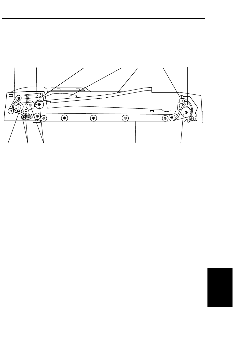
2.1 MECHANICAL COMPONENT LAYOUT
1
12
1. Friction Belt
2. Original Stopper
11
2
10
3
4
7. Inverter Pawl
8. Inverter Roller
5
9
7
8
3. Press Roller
4. Side Fence
5. Original Table
6. Exit Roller
9. Transport Belt
10. Pick-up Rollers
11. Pull-out Roller
12. Feed Roller
3
Feeder
Dual Job
Page 5

ELECTRICAL COMPONENT DESCRIPTION 28 December 1993
3. ELECTRICAL COMPONENT DESCRIPTION
Refer to the electrical component layout on the reverse side of the attached
Point to Point for symbols and index numbers.
Symbol Name Function Index
No.
Motors
M1 Feed-in Drives the feed-in system
(pick-up, feed, pull-out rollers,
separation belts)
M2 Belt Drive Drives the transport belt. 2
M3 Feed-out Drives the feed-out and the
inverter system.
Sensors
S1 DF Position Informs the CPU when the DJF
is being closed so that original
size detection sensors can
check the original size.
S2 Feed-out Checks for original misfeeds and
sets original stop timing when in
auto-reverse mode.
S3 Registration–2 Detects the leading edge of the
original to turn off the feed-in
clutch and to change the feed-in,
belt drive motors speed. Also
detects the original length.
1
5
7
8
10
S4 Original Width–3 Detects the original width. 11
S5 Original Width–1 Detects the original width. 12
S6 Original Width–2 Detects the original width. 13
S7 Registration–1 Detects the trailing edge of the
original to change the belt-drive
motor speed. Also, detects the
original length and original jam.
S8 Original Feed Detects if the originals reach the
feed roller or not.
S9 Original Set Detects if the originals are set on
the feed table.
4
14
15
16
Page 6

28 December 1993 ELECTRICAL COMPONENT DESCRIPTION
Symbol Name Function Index
No.
S10 Pulse Count Counts the pulses generated by
the pulse generator disc to
determine the original length.
Solenoids
SOL1 Inverter Energizes to invert the original
when copying two sided
originals.
SOL2 Stopper Lifts the original stopper and
lowers the press roller to feed
the set of originals to the feed
roller.
SOL3 Separation Transmits drive to the separation
belts.
PCBs
PCB1 DF Main Board Controls all DJF functions. 3
PCB2 Indicator Panel
Contains operator indicators. 21
Board
19
4
9
18
Switches
SW1 Lift Informs the CPU when the DJF
is lifted and also serves as the
jam reset switch for the DJF.
SW2 Feed Cover Detects if the feed cover is
closed.
Clutches
MC1 Feed-in Transmits the feed-in motor
drive to the pick-up and feed
rollers, and to the separation
belts.
6
17
20
Feeder
Dual Job
5
Page 7
BASIC OPERATION 28 December 1993
4. BASIC OPERATION
4.1 ONE-SIDED ORIGINAL FEED
[A]
[A]
[B]
[C]
[D]
When an original is set on the DJF feed table, the leading edge is stopped by
the stopper [A], and the feeler [B] activates the original set sensor. The Insert
Original indicator light goes out and the DJF informs the copier’s CPU that
the originals have been set.
When the Start key is pressed, the copier’s CPU sends the feed-in signal to
the DJF. On receipt of this signal, the stopper solenoid [C] activates to raise
the stopper to allow the originals to be fed in, and to lower the press rollers
[D] to press the originals against the pick-up rollers as shown.
6
Page 8
[B]
28 December 1993 BASIC OPERATION
[A]
[C]
[E]
[D]
[F]
[D]
[F]
[B]
[G]
[E]
The feed-in clutch [A] activates when the DJF receive the feed-in signal.
200ms after the feed-in clutch activate, the feed-in motor feeds all originals to
the feed roller [B].
When the originals reach the feed roller, the stopper solenoid [C]
de-activates to lower the original stopper [D] and to lift up the original press
rollers [E].
When the originals pass through (between the separation belt [F] and feed
roller), only the lowest original is separated and fed onto the exposure glass.
Until then, the feed-in motor rotates slowly (372mm/sec) to ensure proper
original feeding. When the leading edge of the original activates registration
sensor - 2 [G], the feed-in clutch [A] turns off to reduce the mechanical load
and prevent the next original from feeding. Also, the feed motor rotates more
quickly (1250mm/sec).
Feeder
Dual Job
7
Page 9
[A]
BASIC OPERATION 28 December 1993
[C][B]
When the leading edge of the original reaches the exposure glass, the
original is transported by the transport belt [A] (belt drive motor turns on 200
ms after the start key is pressed).
When the trailing edge of the original passes through registration sensor - 1
[B], the feed-in motor turns off. When the trailing edge of the original passes
through registration sensor - 2 [C], the belt drive motor gradually decreases
its speed to stop the original at the proper place on the exposure glass.
200ms after the belt drive motor turns off, the feed-in motor turns on until the
next original activates registration sensor - 1 [B], the next original waits until
the first original copy jobs complete. This operation reduces the original feed
in time.
When the scanner reaches the return position, the copier’s CPU sends the
feed-out and feed-in signals to the DJF CPU in order to exchange the original
for the next original.
When the DJF receives the feed-out signal, the belt drive and feed-out
motors turn on.
When the scanner reaches the return position after scanning the last original,
the copier’s CPU sends only the feed-out signal to feed-out the last original.
If the original is smaller than A4 sideways, the original just copied is
transported to the right side of the exposure glass then waits until the next
original copying is completed. Then the previous original is delivered. This
operation also reduces the original feed-in time.
8
Page 10
28 December 1993 BASIC OPERATION
4.2 TWO-SIDED ORIGINAL FEED
[A]
[B]
Unlike one-sided original feed, the back side of the original must be copied
first to keep the originals and copies in the correct order.
During original feed-in, the sequence is the same as for one-sided feed;
however, the belt drive motor continues rotating until the original reaches the
inverter section. The DJF CPU also energize the feed-out motor and the
inverter solenoid [A] for a short time.
After the inverter mechanism inverts the original (10 pulses after the feed-out
sensor [B] activates), the belt drive motor reverses and the original is fed
towards the original scale. It is stopped at the correct position on the
exposure glass, and the DJF CPU sends the copy start signal.
When the scanner reaches the return position, the copier’s CPU sends the
invert original signal to the DJF CPU in order to make a copy of the front side.
The original is inverted in the same way as for back side copying.
Feeder
Dual Job
9
Page 11
BASIC OPERATION 28 December 1993
4.3 PRESET MODE
[E]
[B]
[D]
[C]
[F]
[A]
Two sets of originals for independent copy jobs can be set on the original tray
at the same time.
While the first set of originals [A] remains on the original tray, both the original
set sensor feeler [B] and original feed sensor feeler [C] are actuated. If the
second set of originals [D] has been set (stopped by the original stopper [E])
and the first set of originals [A] are all fed-in, the original set sensor feeler [B]
is still actuated and only the original feed sensor is deactuated. Therefore,
the copier’s CPU recognizes that the first job is completed.
If the second job is already preset, the second set of originals is automatically
fed to the feed roller [F] in the same manner as the first set of originals was.
10
Page 12
28 December 1993 BASIC OPERATION
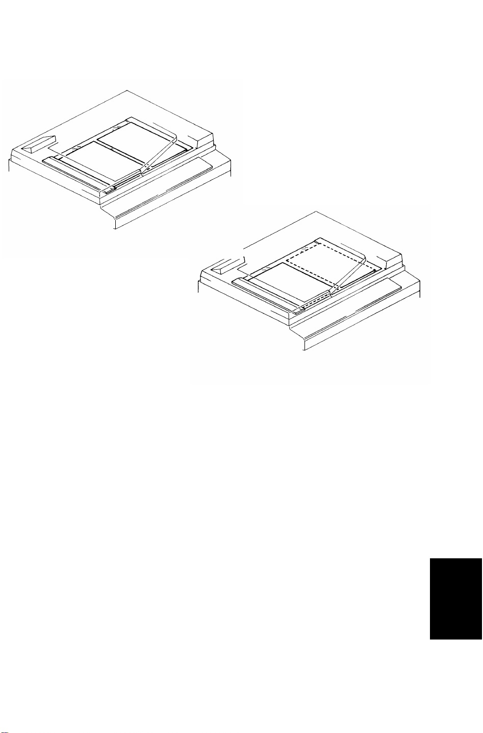
4.4 COMBINE 2 ORIGINALS MODE
4.4.1 Overview
[Fig.1]
[Fig.2]
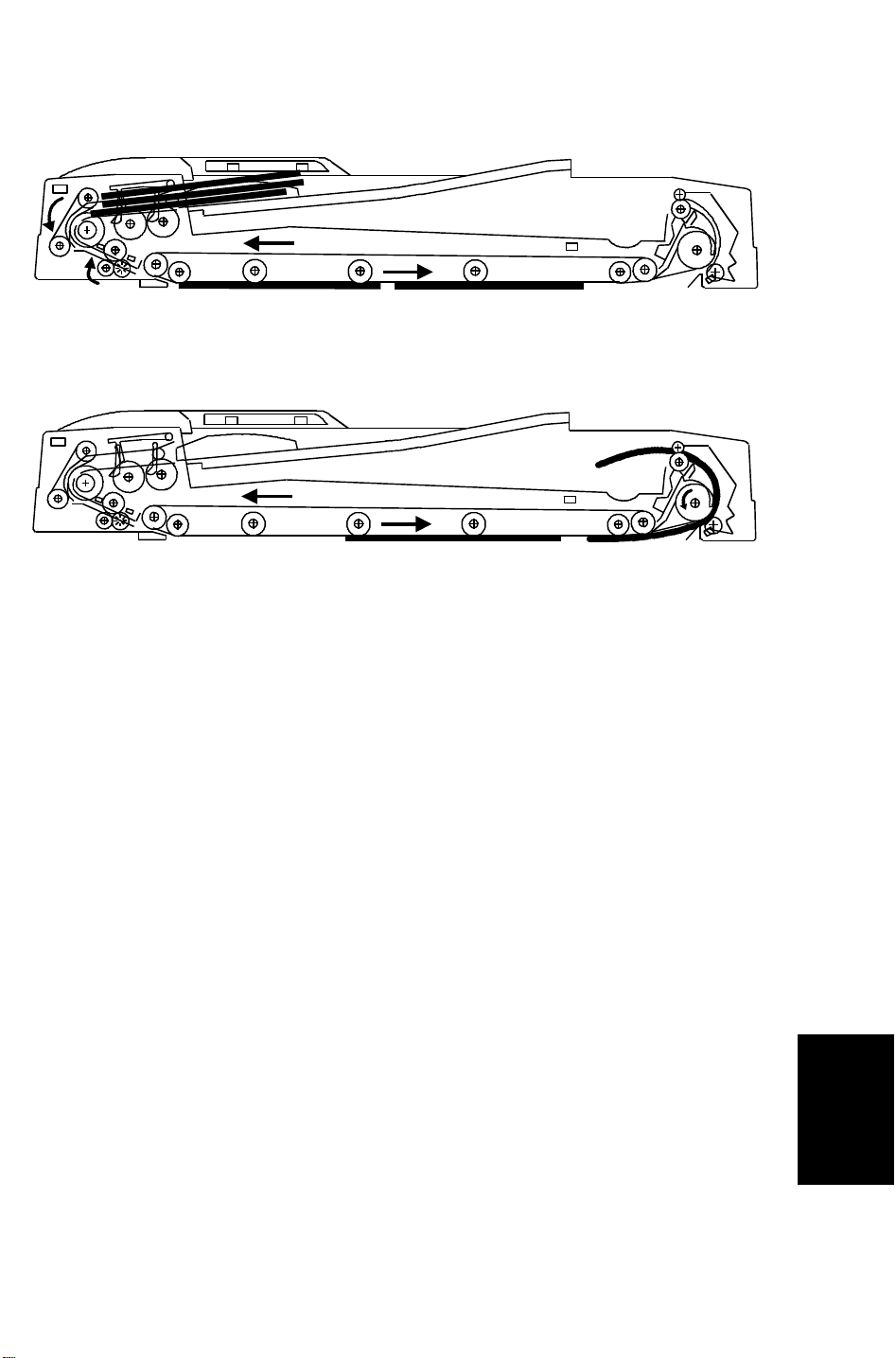
2 originals are fed onto the exposure glass at once in the combine 2 originals
mode as shown in figure 1. This allows copying 2 originals onto one sheet of
paper automatically either in the full size mode or in the reduction mode.
If odd numbered originals are placed on the original table, the first original is
placed on the exposure glass as shown in figure 2.
Only 1-sided originals can be used, and Auto Paper Select (APS) and Auto
Reduce/Enlarge modes cannot be used with this mode.
Feeder
Dual Job
11
Page 13
BASIC OPERATION 28 December 1993
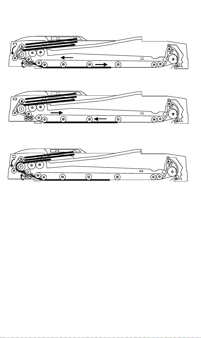
4.4.2 Operation
Figure 1
Figure 2
The DF operation in the combine 2 original mode is as follows:
[Figure 1]
The first original is fed in the same manner as the one-sided original
mode. When registration sensor-2 detects the trailing edge of the first
original, the feed-in and the belt drive motors stop once and the feed-in
clutch turns on again to prepare for the second original feed.
[Figure 2]
As soon as the feed-in and the belt drive motor turn off, the belt drive
motor starts rotating in reverse to align the first original against the
original scale. Then the belt drive motor turns off.
[Figure 3]
50ms after the feed-in motor turns off, the feed-in motor turns on again at
a lower speed (372mm/sec) to feed the second original.
A few pulses (0 ∼ 14 pulses: depends on the DIP switch combinations
102-1 ∼ -4) after the registration sensor-2 is activated by the leading edge
of the second original, the feed-in motor and the feed-in clutch turn off.
Figure 3
12
Page 14
28 December 1993 BASIC OPERATION
Figure 4
[Figure 4]
Soon after the feed-in motor turns off, both the feed-in and the belt drive
motors turn on again at the lower speed (372mm/sec).
After registration sensor-2 detects the trailing edge of the second original,
the feed-in and the belt drive motors turn off and gradually the belt drive
speed reduces to stop the original at the proper place on the exposure
glass.
[Figure 5]
After the copying of these originals is finished, the belt drive motor and
the feed-out motor turn on to feed out the originals. 50mm before the
trailing edge of the first original de-activates the feed-out sensor, both the
belt drive and the feed-out motor rotate at the lower speed to improve
original stacking.
48 pulses after, the belt drive motor turns off and 60 pulses after the
feed-out sensor detect the trailing edge of the second original, the
feed-out motor turns off.
Figure 5
13
Feeder
Dual Job
Page 15
ORIGINAL SEPARATION 28 December 1993
5. ORIGINAL SEPARATION
[E]
[F]
[B]
[C]
[A]
[B]
[D]
[E]
[C]
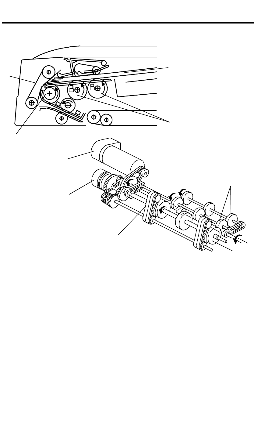
The drive from the feed-in motor [A] is transmitted to the pick-up rollers [B]
and the feed roller [C] through the feed-in clutch [D] as shown. The feed roller
and the friction belts [E] are used to feed-in and separate the originals [F].
Only the bottom original is fed because the friction belt prevents any other
original from feeding.
Original feed starts when the feed roller starts turning and advances the
bottom original of the stack. The feed roller moves the original past the
separation belt because the driving force of the feed roller is greater than the
resistance of the friction belt. The friction belt prevents multiple feeds
because the resistance of the friction belt is greater than the friction between
original sheets.
14
Page 16

28 December 1993 SEPARATION BELT DRIVE MECHANISM
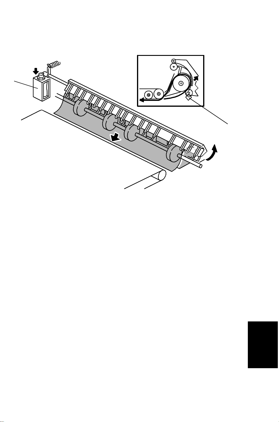
6. SEPARATION BELT DRIVE MECHANISM
[B]
[D]
[A]
[C]
Normally the separation belt is not driven. When the copy job is completed,
the separation solenoid [A] activates for 100ms. to transmit the drive from the
feed-in motor [B] to the separation belts [C] as shown.
By this operation, the part of the friction belt that contacts the feed roller [D]
or the original changes to prevent multiple feeding.
When the pasted original mode is selected, the separation solenoid turns on
to drive the separation belt in the same direction as the feed rollers.
This disables the separation function to reduce the friction between the
original surface and the separation belt.
Feeder
Dual Job
15
Page 17

THIN / THICK ORIGINAL MODES 28 December 1993
7. THIN / THICK ORIGINAL MODES
This document feeder has two different ways of stopping originals at the
correct position on the exposure glass. They are called the thin original mode
and the thick original mode. The mode used is determined by using the
copier’s User Tool No.12.
1. Thin Original Mode
The original is stopped at the correct position on the exposure glass
based on encoder pulse count. The belt drive motor stops shortly after
the original trailing edge passes registration sensor - 2. (Exact timing
depends on registration adjustment.)
In the pasted original mode, the DJF automatically selects this mode.
2. Thick Original Mode
When thick original mode is selected, the belt drive motor remains
energized to carry the original approximately 10 mm pass the left scale.
Then, the belt drive motor pauses and reverses to feed the original back
against the original scale. This forces the original against the left scale
and thus aligns the trailing edge of the original with the scale.
Thick original mode is selected at the factory.
16
Page 18

[E]
[E]
28 December 1993 ORIGINAL SIZE DETECTION
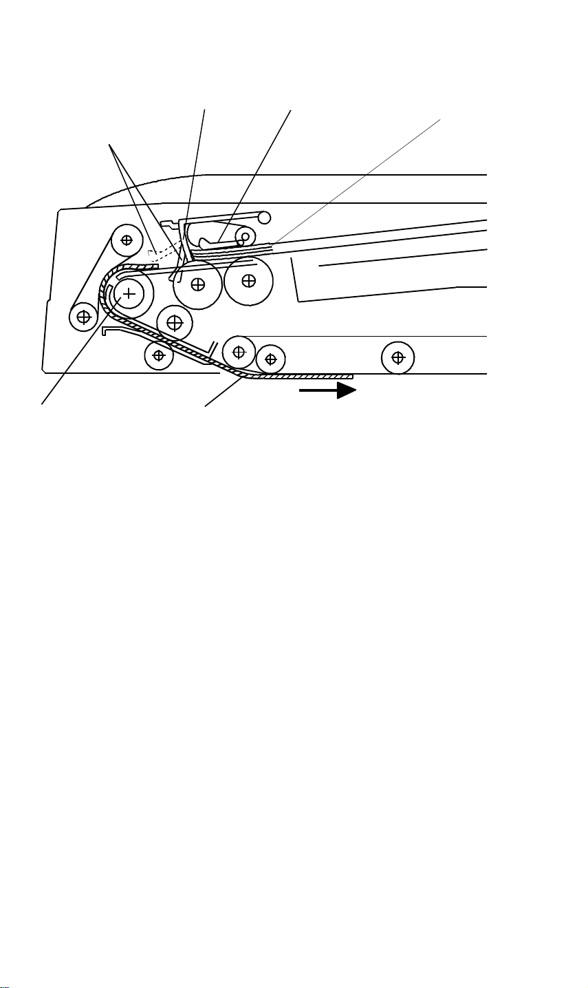
8. ORIGINAL SIZE DETECTION
[F]
The DJF detects original width through the on/off combination of the three
original width sensors -1 [A], -2 [B], -3 [C], it also detects the original length
through the use of the registration sensors -1 [D], -2 [E] and the pulse count
sensor [F].
[D]
[C]
[G]
[A]
[B]
The DJF CPU counts the pulses between registration sensor - 2 [E] on timing
and registration sensor - 1 [D] off timing.
Based on this pulse count, the CPU determine the original length.
The reason for using two registration sensors are:
1) Registration sensor -2 [E] is used to stop the pre-fed original to wait until
the previous original is fed out. For precise control, the original stop
position must be after the pull out rollers [G]. Therefore, registration
sensor -2 is placed after the pull-out roller.
2) Registration sensor -1[D] checks the trailing edge of the original. This
check is used to place the original on the exposure glass.
Enough distance is required between the sensor and the original scale.
Therefore, registration sensor -1 is placed 34.9 mm before sensor -2.
The original size is determined by the combination of the detected original
width and the length.
Feeder
Dual Job
17
Page 19

LIFT MECHANISM 28 December 1993
9. LIFT MECHANISM
➀
➂
[A]
➁
➂
[D]
➀
[B]
When the DJF is opened, the lift springs [A] provide enough force to ensure
that the DJF does not fall onto the exposure glass. When the DJF is closed,
points "➀", "➁", and "➂" are aligned and no upward force is provided to the
DJF.
➁
[C]
The lift switch [B] is actuated when the DJF is closed. The copier then shifts
to the document feeder mode. The lift switch also serves as the reset switch
for DJF misfeeds.
When a book or thick (maximum thickness 60 mm) original is copied, the DJF
acts as a cover for the original as shown in the figure [C]. The lift switch is
turned off during this condition, so the DJF does not function. The tension of
spring [D] returns the DJF to the normal condition after copying a thick
original.
18
Page 20

28 December 1993 ORIGINAL MISFEED DETECTION
10. ORIGINAL MISFEED DETECTION
Registration sensor -1 and the feed-out sensor are used for misfeed checks
to light the original misfeed indicator.
1. One sided original
➀
Registration
Sensor – 1
➂
➁
Feed-out Sensor
➃
Feed-in Motor
Feed-out Motor
➄
Copying
➀: If registration sensor -1 does not activate within 150 pulses after the
feed-in motor starts turning, the CPU determines that the original will not
arrive (ON check).
➁: If registration sensor -1 does not de-activate within 120 pulses, the CPU
determines that the original is still there (OFF check).
➂: If the current paper size data is 40mm longer or 80mm shorter than the
previous original size data (this check is disabled in the mixed size
original mode).
➃: If the feed out sensor does not activate within 125 pulses after the
feed-out motor starts turning, the CPU determines that the original will not
arrive (ON check).
➄: If the feed-out sensor does not de-activate within 60 pulses after the feed
out motor slows down, the CPU determines that the original is still there
(OFF check).
19
Feeder
Dual Job
Page 21

ORIGINAL MISFEED DETECTION 28 December 1993
2. Two sided original
Registration sensor -1 and the feed-out sensor are used for misfeed checks
to light the original misfeed indicator.
Registration ON/OFF check is the same as for one-sided originals.
①
③
④②
Feed-out
Sensor
⑤
Feed-out
Motor
Forward
Belt Drive
Motor
Reverse
1st Copying
2nd Copying
➀: If the feed-out sensor does not activate within 130 pulses after the
feed-out motor starts turning, the CPU determines that the original will not
arrive (ON check).
➁: If the feed-out sensor does not de-activate within 200 pulses, the CPU
determines that the original is still there (OFF check).
➂: If the feed-out sensor does not activate within 130 pulses after the
feed-out motor starts turning, the CPU determines that the original will not
arrive (ON check).
➃: If the feed-out sensor does not de-activate within 200 pulses, the CPU
determines that the original is still there(OFF check).
➄: If the feed out sensor does not activate within 125 pulses after the
feed-out motor starts turning, the CPU determines that the original will not
arrive (ON check).
⑥
➅: If the feed-out sensor does not de-activate within 60 pulses after the feed
out motor slows down, the CPU determines that the original is still there
(OFF check).
20
Page 22

11. TIMING CHART
11.1 DJF Timing Chart (1 sided original mode)
RXD
TXD
Original Set SN
Stopper SOL
Feed-in MC
Original Feed SN
Registration-1
Registration-2
Feed-Out SN
Separation SOL
Feed-in M (M1)
Feed-in
Original set
200 ms
390 ms
480 ms
200 ms
M1: 10 pls
Size
Pulse Count
Original stop
150 ms
M1: 5 pls
200 ms
Feed-out
Feed-in
No original
Size
Original
stop
M1: 5 pls
Feed-out
Feed-out
Feed-out
Feed amount:
M1: 3.7 mm/pls
Belt Drive M (M2)
Feed-out M (M3)
M2: 2.0 mm/pls
M3: 2.7 mm/pls
Registration-1ON
check (within 150 pls)
M3: 60 pls
Feed-out sensor OFF check (within 60 pls)
Feed-out SN ON check (within 125pls)
Incorrect Original Size check
(If more than 40 mm longer or more than 80 mm shorter than previous original).
Registration-1 OFF check (within 200 pls)
21
M3: 60 pls
Page 23

11.2 DJF TIMING CHART (COMBINE 2 ORIGINALS MODE)
RXD
TXD
Original Set SN
Stopper SOL
Feed-in MC
Original Feed SN
Registration-1
Registration-2
Feed-out SN
Separation SOL
Feed-in
Motor (M1)
Original set
Combine: Feed-in
390 ms
480 ms
200 ms
M1:5pls
50 ms
NOTE: 1
0 ~ 14 pls
Combine: Feed-out
Original StopSize
Trailing Edge
Feed-out
Feed-out
M1: 3 pls
M3: 48 pls
Belt drive
Motor (M2)
Feed-out
Motor (M3)
NOTE: Adjustable (0 ~ 14 pls) by DIP SW102
M3: 60 pls
22
Page 24

28 December 1993 INSTALLATION
12. INSTALLATION
12.1 ACCESSORY CHECK
Check the accessories according to the following list:
Description Q’ty
1. Installation procedure.............................................................1
2. Stepped screw........................................................................2
3. Philips screw with flat washer - M5 x 10.................................2
4. New equipment condition report
(for -17, -27 machine only) .....................................................1
5. Envelope (for -17 machine only) ............................................1
23
Feeder
Dual Job
Page 25

INSTALLATION 28 December 1993
12.2 INSTALLATION PROCEDURE
[C]
[D]
[B]
[D]
[A]
CAUTION: When installing the Dual Job Feeder (DJF), make sure that
the copier is unplugged.
1. Remove the tape strips and the cushion [A].
2. While raising the lock plate [B], slide the platen cover [C] to the right and
remove it from the copier.
3. Remove the platen cover mounting screws [D].
24
Page 26

28 December 1993 INSTALLATION
[B]
[A]
[A]
[E]
[C]
[D]
4. Install two stepped screws [A] to hook the DJF.
5. Mount the DJF to the two stepped screws by aligning the holes in the DJF
hinge [B] and the stepped screws, then slide the DJF to the front as
shown.
6. Secure the DJF to the copier (2 screws - M 5 x 10).
7. Remove the small cap [C] on the upper rear cover of the copier then
connect the connector [D] and the fiber optic cable connector [E].
25
Feeder
Dual Job
Page 27

INSTALLATION 28 December 1993
[B]
[A]
[C]
8. Install the 2 ferrite cores to the DJF as follows. (-22, -26, -27, machines
only)
NOTE: The 2 ferrite cores are accessories of the copier.
The following procedures have been added when installing the
optional DJF (machine code A376) to this copier. Locate 2 ferrite
cores inside the plastic bag for the screws.
• Lift the DJF and remove the lower exit cover [A] (4 screws).
• Attach the ferrite core-small [B] to the solenoid harness as
shown.
• Attach the ferrite core-large [C] to the 2 motor harnesses as
shown.
9. Plug in the copier and turn on the main switch.
NOTE: The copier automatically recognizes that the DJF has been
installed.
10. Make copies using the DJF and confirm the copy image.
26
Page 28

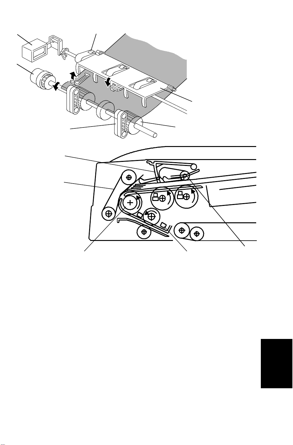
[D]
28 December 1993 INSTALLATION
[C]
[A]
[B]
[F]
[E]
NOTE: Only when the original skew occur, perform the following adjustment.
8. Adjust the height of the DJF by using the adjusting dials [A]. Repeat the
following procedure for each adjustment dial.
1) Close the DJF.
2) Confirm whether or not the copier upper cover [B] and all four stoppers
[C and D] are in contact.
3) If not, loosen the lower dial [E] (rotate counterclockwise) and adjust the
height of the DJF by rotating the upper dial [F].
NOTE: 1. First, adjust the DJF height so that the two front stoppers [C]
contact the upper cover, then adjust the DJF height so that all
four stoppers [C and D] contact the upper cover [B].
2. Rotate the right adjusting dial clockwise to lower the left front
side of the DJF. (Black arrow in the illustration)
3. Rotate the left adjusting dial clockwise to lower the right front
side of the DJF (White arrow in the illustration)
4. If the height adjustment is not correct, then original skew will
occur.
Feeder
Dual Job
27
Page 29

INSTALLATION 28 December 1993
[D]
[C]
[E]
[A]
[B]
4) Lock the adjusting (upper) dials [A] by fully rotating the lock (lower)
dials [B] clockwise.
NOTE: Mostly, height will be proper when the gap [C] is 2 mm. If the
height adjustment is not completed even if the gap [C] is less
than 2 mm, remove the cover [D] (4 screws) then loosen 4
screws [E], and tighten again. Then adjust the height again.
28
Page 30

28 December 1993 SERVICE TABLES
13. SERVICE TABLES
13.1 DIP SWITCHES AND SWITCHES
0: OFF 1: ON ↓: Push
Modes
Motor ON
(speed
Adj.)
MC, SOL
Test
Original
Feed
(Registra-
tion Adj.)
Free run
with original
Free run
Original
Distance
Adj.
(Combine
Originals)
Standard 0 0 0 0 0 0 0 0 0 0 Standard setting
DPS101 DPS102 SW
1 2 3 4 1 2 3 4 101 102
1 1 0 1 1 0 0 0 – – Feed-in motor activates
1 1 0 1 0 1 0 0 – – Belt drive motor activates
1 1 0 1 0 0 1 0 – – Feed-out motor activates
0 0 1 1 1 0 0 0 0 0 Stopper solenoid activates
0 0 1 1 0 1 0 0 0 0 Separation solenoid activates
0 0 1 1 0 0 1 0 0 0 Feed clutch activates
0 0 1 1 0 0 0 1 0 0 Reverse solenoid activates
0 1 0 1 0 0 0 0 ↓ 0 Feeds the original (thick mode)
0 1 0 1 0 0 0 1 ↓ 0 Feeds the original (thin mode)
0 1 0 1 0 0 0 0/1 0 ↓ Delivers the original
0 1 0 1 1 0 0 0 ↓ 0 Feeds the original (2 sided mode)
0 1 0 1 1 0 0 0 0 ↓
0 1 0 1 0 1 0 0 ↓ 0
0 1 0 1 0 1 0 0 0 ↓
1 0 0 1 0 0 0 0 ↓ 0 Thick / 1 sided original mode
1 0 0 1 0 0 0 1 ↓ 0 Thin / 1 sided original mode
1 0 0 1 1 0 0 0 ↓ 0 Thick / 2 sided original mode
1 0 0 1 1 0 0 1 ↓ 0 Thin / 2 sided original mode
1 0 0 1 0 1 0 0 ↓ 0 Thick / mixed size original mode
1 0 0 1 0 1 0 1 ↓ 0 Thin / mixed size original mode
1 0 0 1 0 0 1 – ↓ 0 Combine 2 originals mode
1 0 0 1 – – – – 0 ↓ Stops the free run
0 1 1 0 0 0 0 0 ↓ 0 Starts the free run
0 1 1 0 0 0 0 0 0 ↓ Stops the free run
0 0 0 0 1 0 0 0 – – Shift value +3.5 mm
0 0 0 0 0 1 0 0 – – Shift value +7.0 mm
0 0 0 0 1 1 0 0 – – Shift value +10.5 mm
0 0 0 0 0 0 1 0 – – Shift value +14.0 mm
0 0 0 0 1 0 0 1 – – Shift value –3.5 mm
0 0 0 0 0 1 0 1 – – Shift value –7.5 mm
0 0 0 0 1 1 0 1 – – Shift value –10.5 mm
0 0 0 0 0 0 1 1 – – Shift value –14.0 mm
Reverses the original / Exits the
original
Feeds the original (pasted
original mode)
Exits the original (pasted original
mode)
Function
Feeder
Dual Job
29
Page 31

SERVICE TABLES 28 December 1993
13.2 VARIABLE RESISTORS
VR NO. FUNCTION
101 Adjusts the registration in 1 sided original mode
102 Adjusts the registration in 2 sided original mode
103 Adjusts feed-in motor speed
104 Adjusts belt drive motor speed
105 Adjusts feed-out motor speed
13.3 LEDs
LED NO. FUNCTION
101 Monitors the motor speed (too fast)
102 Monitors the motor speed (normal)
103 Monitors the motor speed (too slow)
13.4 FUSEs
FUSE NO. FUNCTION
101 Protects the 5 V line
102 Protects the 12 V line
103 Protects the 24 V line from feed-in motor failure
104 Protects the 24 V line from belt drive motor failure
105 Protects the 24 V line from feed-out motor failure
30
Page 32

28 December 1993 REPLACEMENTS AND ADJUSTMENTS
14. REPLACEMENTS AND ADJUSTMENTS
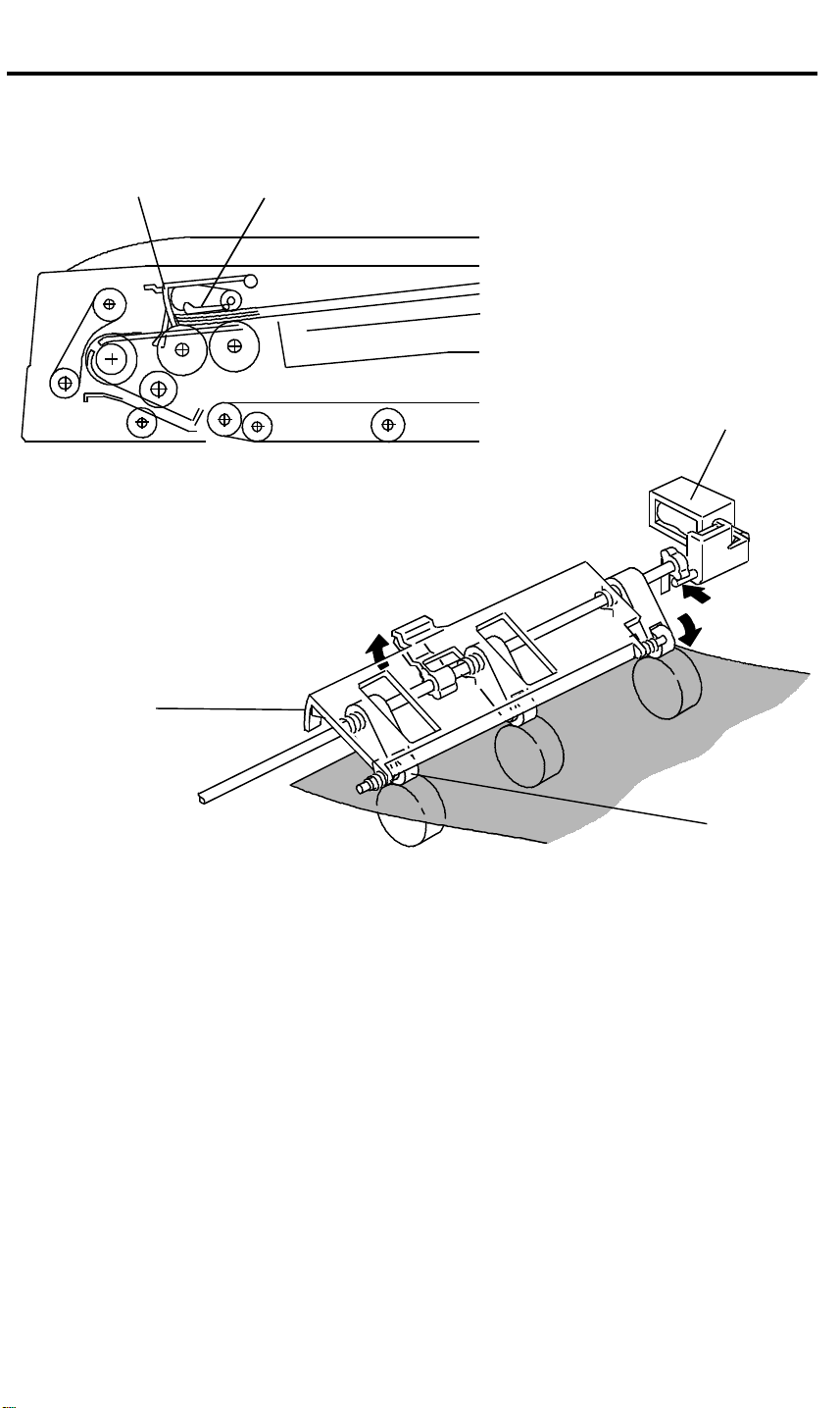
14.1 TRANSPORT BELT REPLACEMENT
[B]
[A]
[C]
[D]
1. Turn off the copier’s main switch.
2. Fully raise the DJF, then remove the front cover [A] (loosen 4 screws).
3. Remove the four screws fixing the transport belt guide assembly [B].
4. Fold the stay [C] as shown.
5. Remove the transport belt [D].
Feeder
Dual Job
31
Page 33

REPLACEMENTS AND ADJUSTMENTS 28 December 1993
[A]
[B]
[D]
6. Install the new belt to the belt guide assembly [A].
[C]
NOTE: When setting the new belt, set the belt between the belt
guides [B].
7. While opening the original guide [C], install the belt guide assembly to the
DJF (4 screws).
8. Install the front cover [D].
9. Confirm the DJF height. (Refer to step 9 of the installation procedure.)
32
Page 34

28 December 1993 REPLACEMENTS AND ADJUSTMENTS
14.2 ORIGINAL TABLE / ORIGINAL GUIDE REMOVAL
M4 x 8
M4 x 6
[A]
[D]
[E]
[F]
[C]
[B]
[H]
[G]
1. Turn off the main switch then open the feed cover [A].
2. Remove the stopper screw [B] then open the original stopper [C].
3. Remove the original table [D] (5 screws).
[H]
[G]
NOTE: When installing the original table, be sure to set the hook [E] in
the hole [F].
4. Before removing the original guide [G], measure and remember the
distance between the original guide and the rear frame [H] as shown.
This is to keep the same original side-to-side registration after the
re-installation.
33
Feeder
Dual Job
Page 35

REPLACEMENTS AND ADJUSTMENTS 28 December 1993
[A]
[B]
[B]
[GOOD]
[B]
[NO GOOD]
5. Remove the original guide [A] (3 screws).
NOTE: 1. When working around the feed rollers, be careful not to
damage the guide mylars [B], and set the guide mylars
correctly as shown.
2. Do not touch the feed roller surface with oily hands.
3. After this replacement, adjust the side-to-side original
registration if necessary.
34
Page 36

28 December 1993 REPLACEMENTS AND ADJUSTMENTS
14.3 FEED ROLLER REPLACEMENT
[B]
[A]
[E]
[F]
[C]
[D]
1. Turn off the main switch then open the feed cover [A].
2. Remove the guide mylars [B] (1 screw each).
3. Remove the snap ring [C].
4. Slide the roller [D] to the rear.
5. Hold the feed roller [E] then slide the shaft to the front, then remove the
feed roller assembly as shown.
6. Remove the four snap rings [F], then remove the feed rollers.
7. Install the new feed rollers, then re-assemble the machine.
NOTE: When installing the feed roller, be sure that the one way bearing
(silver color) is located in the front side (the roller must rotate only
counter-clockwise when the shaft is fixed).
Feeder
Dual Job
35
Page 37

[A]
REPLACEMENTS AND ADJUSTMENTS 28 December 1993
14.4 SEPARATION BELT REPLACEMENT
[C]
[B]
[E]
[D]
1. Turn off the main switch.
2. Fully raise the DJF, then remove the front cover [A] (loosen 4 screws).
3. Remove the screw [B], then remove the feed cover [C].
4. Remove the bracket [D] (1 screw).
5. Remove the four snap rings [E].
36
Page 38

28 December 1993 REPLACEMENTS AND ADJUSTMENTS
[A]
[C]
[D]
[B]
6. Slide the separation belt assembly [A] to the front and remove them.
7. Remove the bushings [B].
8. Remove the pulley [C].
9. Replace the separation belts [D].
NOTE: Do not touch the separation belt with oily hands.
Feeder
Dual Job
37
Page 39

[B]
[C]
[A]
REPLACEMENTS AND ADJUSTMENTS 28 December 1993
14.5 FEED-OUT MOTOR (FEED-OUT UNIT) REMOVAL
[B]
[D]
[E]
[F]
[E]
[E]
1. Fully raise the DJF then remove the front cover. (Refer to Transport Belt
Replacement.)
2. Remove the right cover [A] (4 screws).
3. Remove the two screws [B] fixing the transport belt assembly, then fold
the transport belt stay [C] as shown.
4. Open the original guide [D].
5. Disconnect the four connectors [E].
6. Remove the five screws [F].
[F]
38
Page 40

[F]
28 December 1993 REPLACEMENTS AND ADJUSTMENTS
[A]
[B]
[G]
[C]
[H]
[E]
7. Remove the feed-out unit [A] as shown.
8. Remove the spring [B].
9. Remove the bracket [C] with the feed-out motor from the feed-out unit (3
screws).
NOTE: When re-installing the bracket, be sure to set the arm [D] on the
plunger pin [E].
10. Remove the pulley [F] (1 Allen screw [G]).
11. Remove the feed-in motor (4 screws) [H].
[D]
Feeder
Dual Job
39
Page 41

[D]
[E]
REPLACEMENTS AND ADJUSTMENTS 28 December 1993
14.6 INVERTER SOLENOID REMOVAL AND ADJUSTMENT
[B]
[C]
[A]
ON
OFF
1. Remove the feed-out unit. (Refer to Feed-out Motor Removal.)
2. Remove the inverter solenoid [A] (2 screws).
NOTE: When installing the inverter solenoid, confirm the following:
ONOFF
1) The arm [B] must be set on the plunger pin [C].
2) Manually pull the inverter solenoid plunger and confirm that
when the inverter solenoid does not activate (OFF), the
inverter guide [D] is inside the outer inverter guide [E] and
when the inverter solenoid activates (ON), the inverter guide
is outside the outer inverter guide, as shown.
40
Page 42

28 December 1993 REPLACEMENTS AND ADJUSTMENTS
14.7 BELT DRIVE MOTOR REPLACEMENT
[A]
[B]
[C]
[D]
1. Remove the DJF from the copier (2 screws, 2 connectors, 2 hooks) and
place it on a stable place.
CAUTION: Before disconnecting the connectors, turn off the main
switch of the copier.
2. Remove the motor cover [A] (3 screws).
3. Remove the DF main control board cover [B] (4 screws).
4. Remove the transport belt. (Refer to the The Transport Belt
Replacement.)
5. Remove the right cover [C] (4 screws).
6. Remove the belt guide assembly [D] (6 screws).
NOTE: After re-installing the belt guide assembly, confirm the DJF height
(Refer to the procedure 9 of the Installation Procedure.)
41
Feeder
Dual Job
Page 43

REPLACEMENTS AND ADJUSTMENTS 28 December 1993
[A]
[D]
[C]
[B]
[F]
[E]
7. Remove the left hinge stay [A] (4 screws, 3 connectors).
NOTE: When re-installing the hinge stay, be sure not to pinch the
harness.
8. Remove the two connectors [B].
9. Remove the two screws [C] fixing the belt drive motor bracket.
10. While unhooking the pin [D] from the hole on the feed-in motor bracket,
remove the bracket [E] with the belt drive motor [F].
11. Remove the drive pulley (1 Allen screw) then replace the belt drive motor
(4 screws).
42
Page 44

28 December 1993 REPLACEMENTS AND ADJUSTMENTS
[C]
[B]
[D]
[A]
12. Re-assemble the machine.
NOTE: 1) Before installing the belt guide assembly [A] to the DJF, set
the timing belt [B] on the drive pulley [C].
2) Make sure that the timing belt does not touch any harness.
3) Do not bend the anti-static brush [D].
43
Feeder
Dual Job
Page 45

REPLACEMENTS AND ADJUSTMENTS 28 December 1993
14.8 FEED-IN CLUTCH (FEED-IN UNIT) REMOVAL
[B]
[A]
[D]
[C]
1. Remove the following parts:
1) Original table [A] (refer to Feed Roller Replacement),
2) Feed cover [B] (refer to Separation Belt Replacement),
3) Left hinge stay [C] (refer to Belt Drive Motor Replacement).
2. Remove the table bracket [D] (2 screws).
44
Page 46

28 December 1993 REPLACEMENTS AND ADJUSTMENTS
[B]
[A]
[D]
[E]
[E]
[C]
[D]
3. Disconnect the connectors [A].
4. Remove the feed-in unit [B] (4 screws).
5. Replace the feed-in clutch [C] (1 Allen screw).
NOTE: When installing the clutch on the shaft [D], align the surface of
the clutch stopper [E] and the head of the shaft [D], as shown.
Feeder
Dual Job
45
Page 47

REPLACEMENTS AND ADJUSTMENTS 28 December 1993
14.9 STOPPER SOLENOID REPLACEMENT
[C]
[D]
[B]
[A]
[C]
[D]
1. Remove the feed-in unit. (Refer to Feed-in Clutch Replacement)
2. Remove the bracket [A] with the stopper solenoid (2 screws).
3. Replace the stopper solenoid [B] (2 screws).
NOTE: When installing the stopper solenoid, pay attention to the
following points:
1) The spring [C] must be correctly hooked to the stopper [D], as
shown.
2) Manually pull the stopper solenoid plunger to confirm that the
press rollers firmly contacts the pick-up rollers. When the
pick-up rollers are manually rotated, the press rollers also
rotate. If not, adjust the stopper solenoid position.
46
Page 48

[A]
28 December 1993 REPLACEMENTS AND ADJUSTMENTS
14.10 VERTICAL REGISTRATION ADJUSTMENT
14.10.1 One Sided Original Mode
[C]
[B]
0 ~ 2 mm
1. Remove the small cover at the rear side on the upper DJF cover.
2. Turn on DIP-SW No. 101-2, 4 and 102-4.
3. Set a sheet of A4 / 8 1/2" x 11" (53 ~ 80 g/m2 / 14 ~ 22 lb)sideways paper
on the original table.
4. Push SW 101 [A].
5. After the original stop on the exposure glass, gently raise the DJF so that
the original does not move.
6. Confirm that the gap between the trailing edge of the paper and the
original left scale [B] is within 2 mm.
7. It the gap is larger than 2 mm, adjust the registration by using the copier
SP mode ( SP Adjustment - PAGE 6).
1
NOTE: 1. Before setting the original on the original table again, open and
close the feed unit cover [C].
2. After completing the adjustment, return the DIP switches to the
original condition.
Feeder
Dual Job
47
Page 49

REPLACEMENTS AND ADJUSTMENTS 28 December 1993
14.10.2 Two Sided Original Mode
[A]
[C]
[B]
10 ± 2 mm
1. Remove the copier’s left scale [A] (2 screws).
2. Remove the small cover at the rear side on the upper DJF cover then turn
on DIP SW 101-2, 101-4 and 102-1.
3. Set a sheet of A4 / 8
1/2" x 11" (53 ~ 80 g/m
2
/ 14 ~ 22 lb) sideways paper
on the original table.
4. Push SW 101 [B].
5. After the original stops on the exposure glass, gently raise the DJF so
that the original does not move.
6. Confirm that the gap between the trailing edge of the paper and the left
edge [C] of the original rear scale is 10 ± 2 mm.
7. It the gap is not within specification, adjust the registration by using the
copier SP mode ( SP Adjustment - PAGE 6).
1
NOTE: 1. Before setting the original on the original table again, open and
close the feed unit cover [C].
2. After completing the adjustment, return the DIP switches to
their original condition.
48
Page 50

28 December 1993 REPLACEMENTS AND ADJUSTMENTS
14.10.3 Combine 2 Originals Mode
1. Make a copy in combine 2 originals mode.
2. Adjust the gap between the first original and the second original. It should
be as small as possible. (Do this by changing the DIP SW 102
combination, 3.5mm/step, as shown in the table)
NOTE: Factory settings are all "0" (OFF).
If DIP SW 102-4 is "0" (OFF), the distance between the 1st and
2nd copies is wider (+).
102-4 102-3 102-2 102-1 Shift value
0 0 0 0 0
0 0 0 1 + 3.5 mm
0 0 1 0 + 7.0 mm
0 0 1 1 +10.5 mm
0 1 0 0 +14.0 mm
1 0 0 1 - 3.5 mm
1 0 1 0 - 7.0 mm
1 0 1 1 -10.5 mm
1 1 0 0 -14.0 mm
Feeder
Dual Job
49
Page 51

REPLACEMENTS AND ADJUSTMENTS 28 December 1993
14.11 SIDE TO SIDE REGISTRATION ADJUSTMENT
[D]
[A]
[C]
5 ± 2 mm
1. Remove the small cover at the rear side on the upper DJF cover.
2. Turn on DIP SW 101-2 and 101-4.
3. Set a sheet of A4 / 8 1/2" x 11" (53 ~ 80 g/m2 / 14 ~ 22 lb) sideways
paper on the original table.
4. Push SW 101 [A].
[B]
5. After the original stops on the exposure glass, gently raise the DJF so
that the original does not move.
6. Confirm if the gap between the rear edge of the paper and the original
rear scale is 5 ±2 mm.
7. If the gap is not within the specification, adjust the registration by using
copier’s SP mode ( SP Adjustment - PAGE 4).
1
8. It the gap is not within specification by using SP mode, loosen the eight
screws fixing the original table [B] and the original guide [C] and shift the
original table and the original guide position accordingly.
NOTE: Before setting the original on the original table again, open and
close the feed unit cover [D].
50
Page 52

DPS102
SW102
28 December 1993 REPLACEMENTS AND ADJUSTMENTS
14.12 MOTOR SPEED ADJUSTMENT
DPS101
VR103
VR104
VR105
[A]
[B]
[C]
VR102
LED101
VR101
LED102
LED103
SW101
1. Close the DJF and remove the small cover at the rear side on the upper
DJF cover.
2. Turn on DIP-SW No. 101-1, -2 and -4.
3. Turn on the appropriate DIP switch corresponding to the adjusting motor
to be adjusted (see the table below).
4. Rotate the appropriate VR (see the table below) so that LED102 (green)
[A] lights.
NOTE: If the motor rotation speed is too high, LED101 (red) [B] lights
and if too slow, LED 103 (red) [C] lights.
5. Return the DIP switches to their original condition.
Motor DIP SW VR
Feed-in 102-1 103
Belt drive 102-2 104
Feed-out 102-3 105
Feeder
Dual Job
51
 Loading...