

Ricoh df57 Service Manual

DOCUMENT FEEDER

1 May 1993 SPECIFICATIONS
1. SPECIFICATIONS
Original Size and Weight: – Thin original mode –
Maximum A3/11" x 17"
Minimum B6/51/2" x 81/2"
Weight 41 to 128 g/m2 (11 to 34 lb)
– Thick original mode –
Maximum A3 / 11" x 17"
Minimum B6 / 51/2" x 81/2"
Weight 52 to 128 g/m2 (14 to 34 lb)
– Auto reverse mode –
Maximum A3 / 11" x 17"
Minimum B6 lengthwise /
51/2" x 81/2" lengthwise
Weight 53 to 105 g/m2 (14 to 28 lb)
Original Feed: Automatic feed — ADF mode
Manual feed one by one — SADF mode
Original Table Capacity: 35 sheets / 64 g/m2 (17 lb)
Original Set: Face up. First sheet on top
Original Transport: One flat belt
Copy Speed: 20 copies/minute for A4/8 1/2" x 11" sideways
Power Consumption: 20 W
Dimensions (W x D x H): 670 x 460 x 103 mm (26.4" x 18.1" x 4.1")
Weight: Approximately 9.0 kg (19.916 lb)
Feeder
Document
1
COMPONENT LAYOUT 1 May 1993
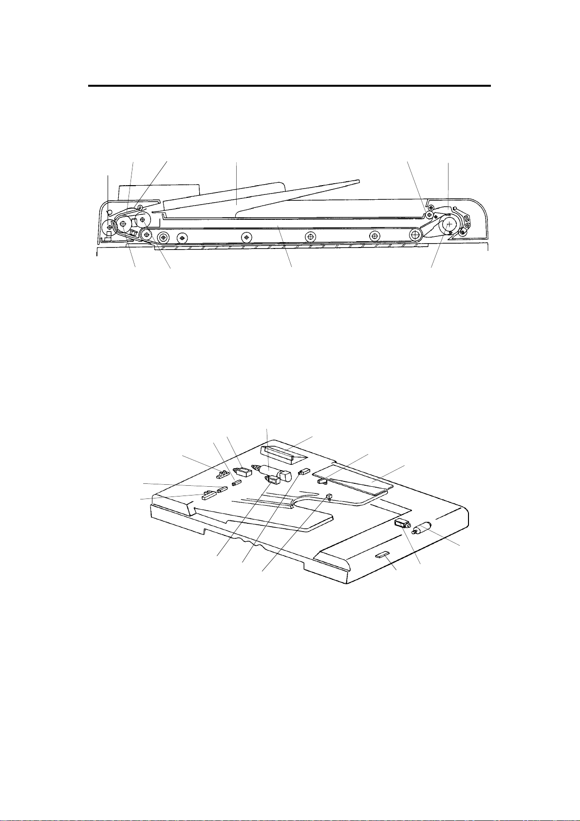
2.COMPONENT LAYOUT
– Mechanical Components –
23
1
4
5
6
10
1. Pulse Generator Disk 6. Inverter Pawl
2. Friction Belt 7. Inverter Roller
3. Pick-up Lever 8. Transport Belt
4. Original Table 9. Pick-up Roller
5. Exit Roller 10. Feed Roller
– Electrical Components –
2
1
9
3
4
5
14
15
13
8
6
7
8
12
7
9
10
11
1. Original Set Sensor 9. DF Main Board
2. Registration Sensor 10. Feed-out Motor
3. Pulse Generator Sensor 11. Inverter Solenoid
4. Original Width Sensor 12. Feed-out Sensor
5. Pick-up Solenoid 13. Original Select Switch
6. Belt Drive Motor 14. Feed-in Solenoid
7. Indicator Panel 15. DF Position Sensor
8. Lift Switch (A054, A072, A111 copiers only)
2

1 May 1993 ELECTRICAL COMPONENT DESCRIPTIONS
3. ELECTRICAL COMPONENT DESCRIPTIONS
Symbol Name Function Index No.
Motors
M1 Belt Drive Motor DC servomotor that drives to the transport belt
and feed-in system (pick-up roller, feed roller,
pull-out roller and relay roller).
M2 Feed-out Motor DC servomotor that drives the feed-out unit of
the DF.
Solenoids
SOL1 Pick-up Solenoid Energizes to press the pick-up lever against
the stack of originals in preparation for original
feed-in.
SOL2 Feed-in Solenoid Turns on to engage the feed-in clutch so
rotation is transmitted to the feed roller,
pull-out rollers, and relay rollers.
SOL3 Inverter Solenoid Energizes to invert the original when copying
two sided originals.
6
10
5
14
11
Switches
SW1 Lift Switch Informs the CPU when the DF is lifted and
also serves as the jam reset switch for the DF.
SW2 Original Select
Switch
Sensors
S1 Original Set
Sensor
S2 Registration
Sensor
S3 Original Width
Sensor
S4 Pulse Generator
Sensor
S5 Feed-out Sensor Checks for original misfeeds and sets original
S6 DF Position Sensor Detects when the document feeder is
Printed Circuit Boards
PCB1 DF Main Board Controls all DF functions. 9
PCB2 Indicator Panel
Board
Selects thick original mode or thin original
mode.
Informs copier CPU that originals have been
placed and causes the Insert Original
indicator to go out.
Sets original stop timing and measures
original length.
Determines the width of the originals. 4
Generates pulses used to measure the
original length.
stop timing when in auto reverse mode.
positioned about 10 cm above exposure
glass. (A111 copier only)
Contains operator indicators. 7
8
13
1
2
3
12
Feeder
Document
3

OVERALL MACHINE CONTROL 1 May 1993
4. OVERALL MACHINE CONTROL
Copier Main Board (PCB1)
RXD
TXD
TXD
RXD
DF Main Board (PCB1)
ROM
CPU
Driver
IC
Driver
IC
Sensors
Switches
Solenoids
Indicators
Belt Drive
Motor
Feed-out
Motor
The DF CPU monitors the input signals from the sensors and switch es, and
energizes the solenoids and the indicator LEDs directly. The belt drive motor
and the inverter motor are cont rolled by the DF CPU through their respective
driver ICs. The exchanged signals are shown in the tables on the next page.
4
31 October 1995 OVERALL MACHINE CONTROL
1. DF → Copier
No. Signal Name Def inition
1 Original Set Originals have been set on the original table
2 Copy Start Allows the copier to start the copy sequence
3 Lift Up The DF has been lifted
4 DF Misfeed A misfeed has occurred in the DF
2. Copier → DF
No. Signal Name Def inition
1 Feed-in Requests the DF to feed in the original
2 Feed-out Requests the DF to feed out the original
3 Invert Original Requests the DF to invert the original
4 Auto Feed Shifts the DF to the auto feed mode
5 Original Stay The machine attempted to use the DF but an original from
the previous copy run remains on the exposure glass
5

BASIC OPERATION 1 May 1993
5. BASIC OPERATION
1. One-sided Original Feed
When an original is inserted face up into the DF, the Inse rt Orig inal indicator
light goes out and the DF informs the copier CPU that originals have been set.
When the Start key is pressed, the copier CPU sends the feed-in signal to
the DF. On receipt of this signal, th e DF ene rgize s the pick-up solen oid, the
feed-in solenoid, and the be lt drive moto r in orde r t o feed -in th e bott om sheet
of the original stack onto the exposure glass. The pick-up solenoid and the
feed-in solenoid remain energized until the original leading edge reaches the
DF registration sensor. The belt drive mo tor t urn s off shortly after the
original’s trailing edge passes the DF registration sensor.
While feeding the original, the DF registra tio n sen sor and the paper width
sensor check the origina l size.
Just when the origina l trailing edge has passed the DF registra tio n sensor,
the DF CPU sends the copy start signal to th e copier.
When the scanner reaches the return position, the copier CPU sends the
feed-out and the feed-in signals to the DF CPU in order to exchange the
original with the next original. At this time, the scanner be gin s retu rnin g to the
home position.
When the scanner comes to th e ret urn position after scannin g th e last
original, the copier CP U only sen ds the feed-out signal in ord er to fee d-out
the last original.
6

1 May 1993 BASIC OPERATION
2. Two-sided Original Fee d
Unlike one-sided original feed, the back side of the original must be copied
first to keep the originals and copies in the correct order.
During original feed-in, the sequence is the same as fo r one-side d feed ;
however, the DF CPU also energizes the in vert er mot or an d th e inverter
solenoid a short time af te r t he origin al trailing edge has passed the DF
registration sensor. The belt drive motor continues to feed the origin al un til
the original leading edge passe s the fee d-o ut sensor. At this point the inverter
mechanism inverts the original, in preparation for copying the back side .
Then the belt drive motor reverses and th e original is fed towards the left
scale and is aligned against the scale. The DF CP U send s the copy start
signal a short time afte r the origin al trailing edge has passed the feed-out
sensor.
When the scanner reaches the return position, the copier CPU sends the
invert original signal to the DF CPU in order to make a copy of the front side.
The original is inverted in the same way as for back side copying.
3. Semi-automatic Document Feed
If a single original is inserte d int o the original table and cop ied , the DF shifts
to the semi-automatic feed mode and lights the Auto Feed ind icat or. The
Auto Feed indicator remains on for five secon ds after the copier main motor
stops. If another origina l is inserted within that five-second pe riod , it is
automatically fed and copied.
Feeder
Document
7

POWER DISTRIBUTION 1 May 1993
6.POWER DISTRIBUTION
6.1A110/A054 COPIERS
+12V
Regulator
IC
5V
(PCB1)
AC Drive
Board
(PCB2)
115Vac
220/230/240Vac
Option
Transformer
(TR2)
26Vac
10Vac
Option DC
Power Supply
Board
(PCB6)
+24V
+24V (VA)
+5V (VC)
DF Main Board
The DF uses three DC power levels: +24 volts, +12 volts, and +5 volts.
When the main switch is turned on, the option tra nsf orme r re ceive s the wall
outlet ac power through the ac drive board and outputs 10 volts ac and 26
volts ac to the option dc power supply board. The option dc power supply
board then converts the 10 volts ac input to +5 volts dc and the 26 volts ac
input to +24 volts. Then, those two dc voltages are supplied to the DF main
board.
The regulator IC on the DF main board further steps down the +24 volts to
+12 volts.
8

1 May 1993 POWER DISTRIBUTION
6.2 A111 COPIER
AC Drive
Board
(PCB2)
115Vac
220/230/240Vac
Main
Transformer
(TR1)
31Vac
10Vac
Main DC
Power
Supply
Board
(PCB3)
+24V (VA)
+5V (VC)
Copier
Main
Board
(PCB1)
+24V
+24V (VA)
+5V (VC)
DF Main Board
+12V
Regulator
IC
5V
(PCB1)
The DF uses three dc power levels: +24 volt s, +12 volts, and +5 volts.
When the main switch is turned on, th e main transformer receives the wall
outlet ac power thro ugh the ac drive board and output s 10 volt s ac and 31
volts ac to the main dc power supply board. The main dc power supply board
then converts the 10 volts ac inpu t to +5 volts dc an d th e 31 volts ac input to
+24 volts. Then, those two dc voltages are supplied to the DF main boa rd
through the copier main board.
The regulator IC on the DF ma in board further steps down the 24 volts to +12
volts.
Feeder
Document
9
ORIGINAL FEED 1 May 1993
7. ORIGINAL FEED
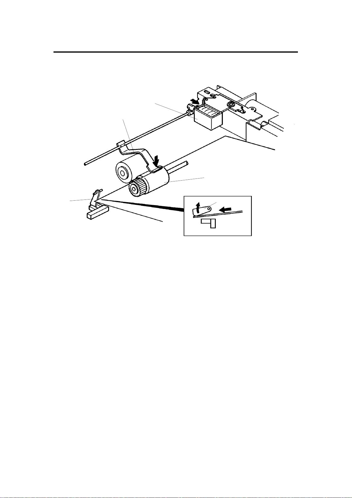
7.1 ORIGINAL PICK-UP
[B]
[C]
[D]
[A]
After setting the origina ls on th e orig ina l tab le, the origin als con ta ct th e feeler
[A] of the original se t sen sor an d cau se the feeler to move out of th e sen sor.
The DF then sends the orig ina l set signal to the copier CPU to inform it that
the DF will be used. When the Start key is presse d, the pick-up solenoid [B]
is energized. The original sta ck is then presse d between the pick-up lever [C]
and pick-up roller [D]. The rotation of the pick-up roller advances the bo tt om
original.
[A]
10

[B]
1 May 1993 ORIGINAL FEED
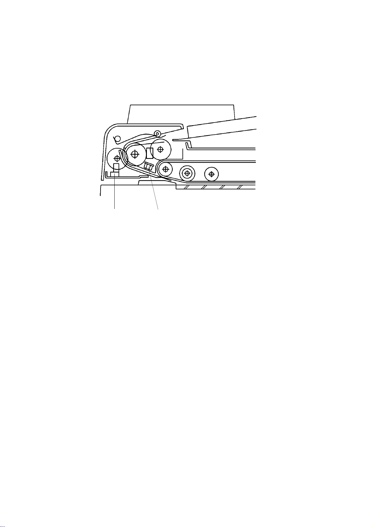
7.2 ORIGINAL SEPARATION
[A]
[B]
[C]
[A]
The feed roller [A] and the friction belt [B] are use d to fee d-in and sepa rat e
the originals [C]. Only the bottom original is fed because the friction belt
prevents any other origin als fro m f eeding.
Original feed starts when the feed roller starts turning and advances the
bottom original of the stack. The feed roller moves the original past the
friction belt because the driving force of the feed roller is great er than the
resistance of the friction belt . The friction belt prevents multiple feeds
because the resistance of the frict ion belt is great er th an the frictio n be twe en
original sheets.
Feeder
Document
11

[E]
[D]
ORIGINAL FEED 1 May 1993
7.3 ORIGINAL FEED-IN MECHANIS M
[C]
[G]
[B]
[A]
[F]
The belt drive motor [A] drives the pick-up roller [B], the feed ro ller [C] , the
pull out roller [D], the relay roller [E], and tra nsp ort belt [F] via a feed clutch
and a gear train.
The pick-up and feed-in soleno ids are ene rgize d 10 0 milliseco nd s aft er th e
Start key of the copier is pressed. Then 100 milliseconds after the soleno ids
are energized, the belt drive motor starts turning. The pulse genera tor disc
[G] always turns when the belt drive motor is on.
Slightly after the original trailing edge passes the reg istra tio n sen sor, the
relay rollers and the transport belt sto p turnin g.
12

1 May 1993 ORIGINAL FEED
This document feed er ha s two dif ferent ways of stopping orig inals at the
correct position on the exposu re gla ss. They are called the "thin original
mode" and the "thick original mode". The mode used is determin ed by the
original select switch [A].
[A]
– Original Select Switch –
1. Thin Original Mode
The original is stopped at th e correct position on the exposure glass ba sed
on encoder pulse count. The belt drive mot or stops shortly after the original
trailing edge passes the DF registra tio n sensor. (Exact timing depends on
registration adjustme nt.) Thin original mode is selected at the factory.
2. Thick Original Mode
When thick original mode is selecte d, the belt drive mot or rema ins en erg ized
for an additional 30 encoder pulses as comp ared to thin original mode. Then,
the belt drive motor pauses and reverse s f or 21 pulse s. This forces the
original against the left scale and thu s align s the edge of the origin al with the
scale.
After the exposu re cycle is completed, the copier send s the fee d-o ut signal to
the DF CPU and the belt drive and feed out motors start turning. At this time,
the copied original f ee ds out an d the next original feeds in.
Feeder
Document
13
ORIGINAL FEED 1 May 1993
7.4 ORIGINAL SIZE DE TECTI O N
[B]
[A]
The DF determines original size (bot h widt h and len gt h) th rou gh the use of
the original width sensor [A], registration sensor, and pulse generat or sensor
[B]. The original’s length is calculated by counting the number of pulses from
the pulse generator while th e reg istration sensor is on.
Original size detection is necessary for the feed-in /feed-out timing of the DF.
14

1 May 1993 ORIGINAL FEED
7.5 ORIGINAL INVERSION MECHANI SM
[D]
[C]
[E]
[B]
1)
[D]
[A]
The two sided originals are invert ed in the feed-out unit.
1) When the copier Start key is pressed, the two sid ed original is fed into the
feed-in unit, passing over th e DF re gist ration sensor [A]. The fee d-o ut
motor [B] and the inverter sole no id [C] turn on 100 milliseconds after the
original trailing edge passes the registratio n sen sor. When the invert er
solenoid turns on, the inverter pawls [D] rotate counterclockwise.
15
Feeder
Document

ORIGINAL FEED 1 May 1993
2) 4)
3) 5)
6)
2) The original passes over the exposure glass and feeds into the feed-out
unit.
3) The original is directed onto the exposure glass aga in by th e inverter
pawls. The belt drive motor now reve rses 14 0 milliseco nd s aft er th e feed
out sensor [E] turns on. The transport belt then moves the origin al to ward
the left scale. Slightly before the original reaches the left scale, the belt
drive motor drops to half spee d. This is to prevent damaging the edge of
the original against the left scale .
When the original leading edge reach es th e lef t scale , th e belt drive motor
stops. At the same time, th e feed-out motor and the inverter solenoid turn
off.
4) After the reverse side of the original is exposed, the belt drive moto r, th e
feed-out moto r, and the inverter solenoid turn on, and the origin al is fed
into the inverter section . (This is the same as ste p 2 ab ove .)
5) The original is fed onto the exposure glass again as in step 3 above. The
front side of the orig ina l is th en co pie d.
6) After the front side of the original has been expo sed, the original is fed
out from the DF.
16

1 May 1993 ORIGINAL FEED
7.6 ORIGINAL FEED- OUT ME CHANI SM
[A]
[D]
[C]
[B]
The exit rollers [A] are driven by the inverter motor [B]. When the document
feeder receives the feed out sign al fro m t he copier, the transport belt and the
exit rollers start turning simulta neou sly. The tran spo rt belt carrie s the origin al
to the inverter rollers [C] and the exit rolle rs take over the original feed-out .
When the original trailing edge passes th e feed -ou t sensor [D], the feed-out
motor drops to half of its normal spee d for 2 20 millise con ds an d then stops.
The lower speed preven ts un eve n stacking of originals. For A3 or double
letter size originals, th e feed-out motor speed does n ot chan ge due to th e
length of the originals.
Feeder
Document
17

ORIGINAL FEED 1 May 1993
7.7BELT DRIVE MOTOR CIRCUIT
DF Main Board (PCB 1)
CPU
Speed
Data
ON/OFF
Forward/
Reverse
Driver
IC
PWM
Driver
Circuit
+5V
Phase A
Phase B
CN102-1
CN102-2
CN103-1
CN103-2
CN103-3
CN103-4
Belt Drive
Motor
Encoder
A dc servomotor is used as the belt drive motor. The d river IC con tro ls the
speed of the belt drive motor. The CPU sends the speed data (programmed)
to the driver IC. The driver IC sends the pulse-wid th-modulation (PWM)
signal to the driver circuit, which sends the motor drive pulses.
An encoder in the servomotor has two magnetic sensors that generate two
pulse signals (phase A and B). The driver IC monitors the belt speed and
direction with these pulse signals and uses the signals to regulate the motor’s
speed.
18

1 May 1993 ORIGINAL FEED
7.8FEED-OUT MOTOR CIRCUI T
DF Main Board (PCB 1)
CN104-A2
FG
CPU
High/Low
ON/OFF
Driver
IC
AC Feedback
Voltage
Regulation
Motor
Drive
Circuit
CN104-A15
CN104-B8
CN104-A12
Feed-out
Motor
The DF CPU sends the speed data (high or low) to the driver IC and the
motor drive circuit. The motor drive circuit creates the PWM signal and sends
the motor drive pulses to the feed-out motor.
The frequency generator of the feed-out motor makes a very low voltage ac
signal which is fed back to the driver IC. The driver IC monitors the
frequency of this ac signal and based on the frequency it regulates the
motor speed.
19
Feeder
Document

ORIGINAL FEED 1 May 1993
7.9INPUT AND OUTPUT CIRCUITS
Original Set Sensor
P
S
CN104-B1
CN104-B9
CN104-B15
DF Main Board (PCB1)
+5V
[ 12]
[ 12]
CN104-A10
CN104-A17
Lift SW (SW1)
Pulse Generator Sensor
P
S
Registration Sensor
P
S
Original Width Sensor
P
S
Feed-out Sensor
P
S
Original Select SW
P: Photoreceiver
S: Schmitt Trigger Circuit
Feed Out
Motor
CN104-B2
CN104-A9
CN104-B17
CN104-B11
CN104-B16
CN104-A11
CN104-A1
CN104-B10
CN104-A16
CN104-A5
CN104-B8
CN104-A12
+5V
[0-12]
[ 5]
[ 5]
+5V
[ 5]
[ 5]
[ 0 0/24]
GND
CPU
Forward
[ 0 0/24]
Return
[ 0 0/24]
+24V
[ 24]
+24V
[ 24]
+24V
[ 20]
[ 19]
[ 20]
CN104-B6
CN104-A3
CN104-A6
CN104-B14
CN104-B5
CN104-A13
Insert Original
CN104-B12
Auto Feed
CN104-A4
Misfeed
CN102-1
CN102-2
Pick-up
SOL
Inverter
SOL
Indicator Panel
Belt Drive
Motor
The above devices are directly controlled and monitored by the CPU. The
solenoids and indicator panel are energized with +24 volts. The sensors and
switches are energized with +12 volts or +5 volts.
To energize a solenoid or indicator, the CPU drops the connected trigger line
from +24 volts to LOW. The CPU monitors the input lines of the sensors and
switches to determine when they are activated.
20

[B]
1 May 1993 LIFT MECHANISM
8. LIFT MECHANISM
[A]
[C]
[D]
[G]
[A]
[F]
[E]
When the document feeder is ope ne d, the lift springs [D] provide enough
force to ensure that the document feeder does not fall onto the exposure
glass. When the document fe eder is clo sed , po int s "A" , "B", and "C" are
aligned and no such force is provided to the document feed er.
[B]
[C]
The lift switch [E] is actuated when the docu men t fe ed er is closed . The copier
then shifts to the document feeder mode. The lift switch also serves as th e
reset switch for document fe ed er misfe ed s.
When a book or thick (maximum thickness 60 mm) original is copied, the DF
acts as a cover for the original a s shown in the figu re [F] . The lift switch is
turned off during th is cond ition, so the DF does not function. The tension of
spring [G] returns th e DF t o th e no rmal con dition after copying a thick orig ina l.
21
Feeder
Document

ORIGINAL MISFEED SENSING 1 May 1993
9. ORIGINAL MISFEED SENSING
The registration sensor and the fe ed-out sensor are used for misfeed checks.
1. One sided original
Registration Sensor
ON check (685 ms)
Feed-out Sensor
Belt Drive Motor
OFF check (1250 ms)
ON check (1250 ms)
OFF check (1250 ms)
Feed-out Motor
If the registration sensor is not actu at ed wit hin 685 millise con ds af te r the belt
drive motor starts turning, the Origin al Misfe ed indicator lights (ON check).
If the registration sensor does no t tu rn of f with in 1, 25 0 milliseco nds, th e CPU
determines that there has been an original misfeed (O FF check). The
Original Misfeed indicato r also ligh ts if the feed-out sensor is not actu at ed
within 1,250 milliseconds after the feed-out motor starts turning (ON check)
or if the feed-out sensor does not turn off within 1,250 milliseconds after the
feed-out sensor is actuate d (OFF che ck).
22

1 May 1993 ORIGINAL MISFEED SENSING
2. Two sided original
Registration
Sensor (RS)
RS ON check (685 ms)
Feed-out
Sensor (FS)
Inverter Solenoid
RS OFF check (1250 ms)
100 ms
FS OFF check (1250 ms)
FS ON check (1250 ms)
Belt Drive Motor
Feed-out Motor
Forward
Reverse
The registration ON/OFF check is the same as for one-sided originals. Th e
inverter motor and the inve rte r solen oid turn on 100 milliseconds after the
registration senso r t urn s off. If the feed-out sensor is not actuated within
1,250 milliseconds after the feed-out motor starts turning, the Original
Misfeed indicator lights (ON check). The Origin al Misfeed indicator also lights
if the feed-out sensor does not turn off within 1,250 milliseconds after the belt
drive motor reverses (OFF check).
If a previous original remains on the expo sure glass af ter manual copying
and DF feed is attempted, the original misfeed indicat or ligh ts. When the DF
is lifted and the previous original is removed, DF copying is permitted.
23
Feeder
Document
 Loading...