

Ricoh DF56, A497 Service Manual

AUTO REVERSE
DOCUMENT FEEDER
(Machine Code: A497)

12 February 1992 SPECIFICATIONS
1. SPECIFICATIONS
Original Size: Max A3, 11" x 17"
Min B6, 5
Original Weight: 42~12 8 g/ m2 (11~34lb)
-SADF. ADF
52~104 g/m2 (14~28lb)
-SADF. ADF. ARDF
Original Feed Mode: Automatic feed ADF Set: Face-up, 1st sheet on top
Manual feed one by one SA DF
Auto Reverse Feed ARDF
1/2
" x 8
1/2
"
Original Table Capacity: Max 50 shee ts (A4 /8
" x 11)
1/2
52 g/m2 (14lb)
Original Separation: F ee d an d Fr ictio n Be lts
Original Transport: One fla t be lt
Original Stop System: Dc servo motor control system
Copying Speed (FT5233): Continuous cop y
33 copies/minute (A4/8
Single copy
31 copies/minute (A4/8
Power Source: 24V from copier, 1.8A
Power Consumption: 45W
Dimensions
(W x D x H):
670 x 468 x 120 mm
(26.4" x 18.5" x 4.8")
Weight: Approximately 9.5 kg (21lb)
" x 11" sideways)
1/2
" x 11" sideways)
1/2
ARDF
1
SPECIFICATIONS 10 July 1992
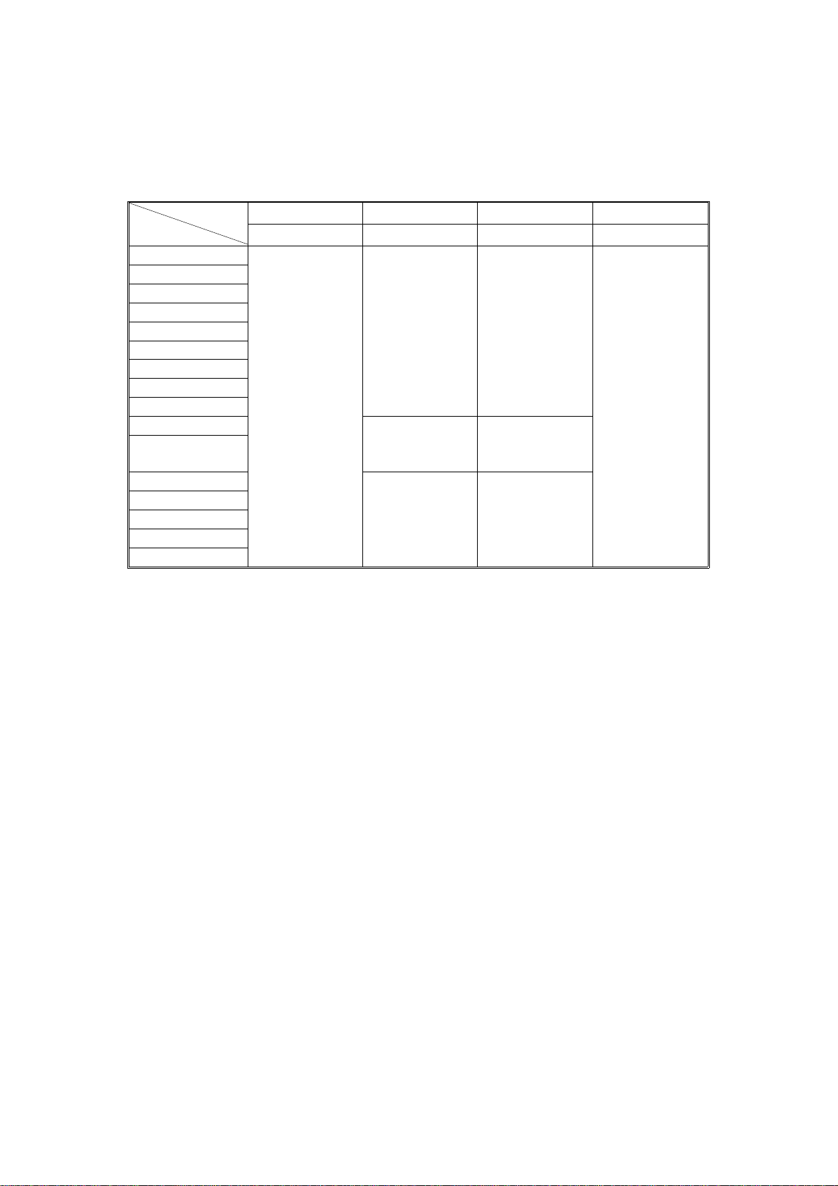
TABLE:
WEIGHT
SIZE
41 - 51 (g/m2) 52 - 81 82 - 104 105 - 128
11 - 13 (lb) 14 - 22 23 - 28 29 - 34
A3L
A4S
A4L
A5S
A5L
B4L
B5S
B5L
B6L
50 sheets
(ADF, SADF
only)
B6S 50 sheets
5
1/2" x 81/2"S
11" x 17"L
8
1/2" x 14"L
8
1/2" x 11"S
8
1/2" x 11"L
5
1/2" x 81/2"L
"L" means lengthwise.
"S" means sideways.
50 sheets
(ARDF, ADF,
SADF)
(ADF, SADF
only)
50 sheets
(ARDF, ADF,
SADF)
30 sheets
(ARDF, ADF,
SADF)
25 sheets
(ADF, SADF
only)
30 sheets
(ADF, SADF
only)
30 sheets
(ARDF, ADF,
SADF)
2

MECHANICAL COMPONENT LAYOUT 12 February 1992
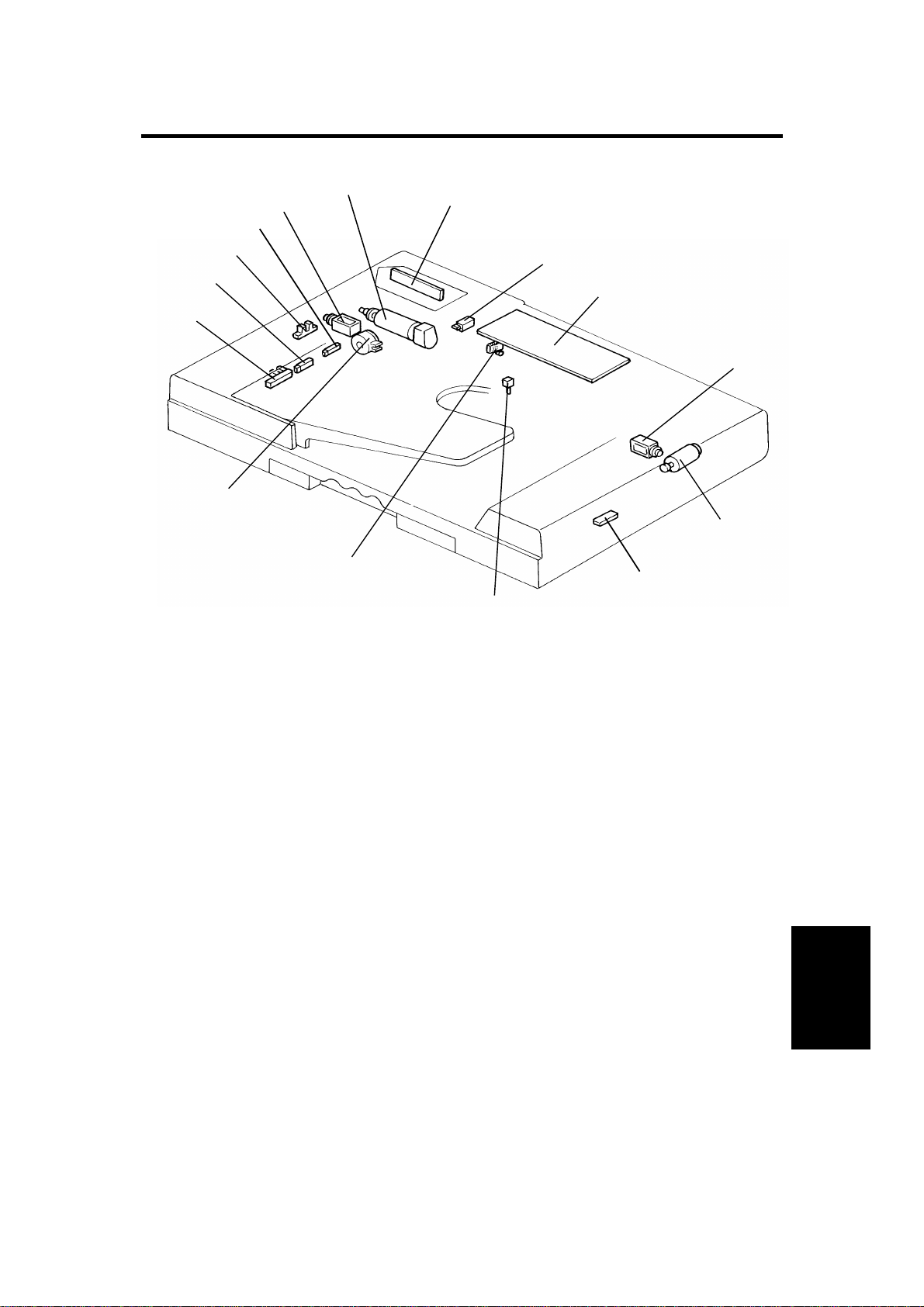
2. MECHANICAL COMPONENT LAYOUT
1
2
3
4
5
6
10
1. Pulse Generator Disk
2. Friction Belt
3. Pick-up Lever
4. Original Table
5. Exit Roller
9
8
6. Inverter Pawl
7. Inverter Roller
8. Transport Belt
9. Pick-up Roller
10. Feed Roller
7
2
12 February 1992 ELECTRICAL COMPONENT LAY OUT
3. ELECTRICAL COMPONENT LAY OUT
6
5
4
7
3
2
1
15
14
1. Original Set Sensor
2. Registration Sensor
3. Pulse Generator Sensor
4. Original Width Sensor
8
9
10
11
12
13
9. DF Main Board
10. Inverter Solenoid
11. Feed-out Motor
12. Feed-out Sensor
5. Pick-up Solenoid
6. Belt Drive Motor
7. Indicator Panel
8. DF Position Sensor
13. Original Select Switch
14. Lift Switch
15. Feed-in Clutch
ARDF
3

ELECTRICAL COMPONENT DESCRIPTIONS 12 February 1992
4. ELECTRICAL COMPONENT DESCRIPTIONS
MOTORS
NAME FUNCTION LOCATION
DC servomotor that drives to the transport
Belt Drive Motor
Feed-out Motor
SOLENOIDS
NAME FUNCTION LOCATION
Pick-up Solenoid
Inverter Solenoid
belt and feed-in system (pick-up roller, feed
roller, pull-out roller and relay roller).
DC servomotor that drives the feed-out unit
of the DF.
Energizes to press the pick-up lever against
the stack of originals in preparation for
original feed-in.
Energizes to invert the original when
copying two sided originals.
6
11
5
10
SWITCHES
NAME FUNCTION LOCATION
Lift Switch
Original Select
Switch
Informs the CPU when the DF is lifted and
also serves as the jam reset switch for the
DF.
Selects thick original mode or thin original
mode.
14
13
4

12 February 1992 ELECTRICAL COMPONENT DESCRIPTIONS
SENSORS
NAME FUNCTION LOCATION
Original Set
Sensor
Registration
Sensor
Original Width
Sensor
DF Position
Sensor
Pulse Generator
Sensor
Informs the main system’s CPU that
originals have been placed and causes the
Insert Original indicator to go out.
Sets original stop timing and measures
original length.
Determines the width of the originals. 4
Informs the CPU when DF is being closed
so that APS sensor can begin checking the
original size.
Generates pulses used to measure the
original length.
1
2
8
3
Checks for original misfeeds and sets
Feed-out Sensor
original stop timing when in auto reverse
12
mode.
MAGNETIC CLUTCH
NAME FUNCTION LOCATION
Feed-in Clutch
Energizes to rotate the feed roller, pull-out
rollers, and relay roller
PRINTED CIRCUIT BOARDS
NAME FUNCTION LOCATION
DF Main Board Controls all DF functions. 9
Indicator Panel
Board
Contains operator indicators. 7
15
ARDF
5

BASIC OPERATION 12 February 1992
5. BASIC OPERATION
1. One-sided Original Feed
When an original is inserted into the DF, the Insert Original indicator light
goes out and the DF informs the main system’s CPU that originals have been
set.
When the Start key is pressed, the main system’s CPU sends the feed-in
signal to the DF. On receipt of this signal, the DF energizes the pick-up
solenoid, the feed-in clutch, and the belt drive motor in order to feed-in the
bottom sheet of the original stack onto the exposure glass. The pick-up
solenoid and the feed-in clutch remain energized until the original’s leading
edge reaches the DF registration sensor. The belt drive motor turns off 2,088
encoder pulses after the original’s leading edge passes the DF registration
sensor.
While feeding the original, the DF registration sensor and the original width
sensor check the original size.
Shortly before the belt drive motor turns off, the DF CPU sends the copy start
signal to the main system. On receipt of the signal, the main system’s CPU
starts the copy cycle.
When the scanner reaches to the return position, the main system’s CPU
sends the feed-out and the feed -in signals to the DF CPU in order to
exchange the original with the ne xt or ig ina l .
When the scanner comes to the r et urn posit i on aft er scan nin g th e last
original, the main system’s CPU only sends the feed-out signal in order to
feed-out the last original.
2. Two-sided Original Feed
Unlike one-sided original feed, the back side of the original must be copied
first to keep the originals and cop i es in th e cor rect order.
During original feed-in, the sequence is the same as for one-sided feed;
however, the DF CPU also energizes the feed-out motor and the inverter
solenoid a short time after the original’s leading edge has passed the DF
registration sensor. The belt drive motor continues to feed the original until
85 milliseconds after the original leading’s edge passes the feed-out sensor.
At this point the inverter mechanism inverts the original, in preparation for
copying the back side. Then the belt drive motor reverses and the original is
fed towards the original stopper and is stopped at the correct position on the
exposure glass. The DF CPU sends the copy start signal a short time after
the original’s trailing edge has passed the feed-out sensor.
6

12 February 1992 BASIC OPERATION
When the scanner reaches to the return position, the main system’s CPU
sends the invert original signal to the DF CPU in order to make a copy of the
front side. The original is inverted in the same way as for back side copying.
3. Semi-automatic Document Feed
If a single original is inserted into th e or ig ina l tab le an d cop i ed , th e DF shifts
to the semi-automatic feed mode and lights the Auto Feed indicator. The
Auto Feed indicator remains on for four seconds after the main system’s
main motor stops. If another original is inserted within that fo ur - se cond
period, it is automatically fed an d copied.
ARDF
7
ORIGINAL FEED 12 February 1992
6. ORIGINAL FEED
6.1 ORIGINAL PICK-UP
[A]
[C]
[B]
[D]
After setting the origina l s on the or ig ina l tab le, the originals contact the feele r
[A] of the original set sensor an d cau se th e feeler to move out of the sensor.
The DF then sends the original set signal to the main system’s CPU to inform
it that the DF will be used. When the Start key is pressed, the pick-up
solenoid [B] is energized. The original stack is then pressed between the
pick-up lever [C] and pick-up roller [D]. The rotation of the pick-up roller
advances the bottom original.
8
12 February 1992 ORIGINAL FEED
6.2 ORIGINAL SEPARATION
[B]
[A]
[B]
[C]
[A]
The feed roller [A] and the friction belt [B] are used to feed-in and separate
the originals [C]. Only the bottom original is fed because the friction belt
prevents any other originals from feeding.
Original feed starts when the feed roller starts turning and advances the
bottom original of the stack. The feed roller moves the original past the
friction belt because the drivin g fo r ce of the feed roller is greater than the
resistance of the friction belt. The friction belt prevents multiple feeds
because the resistance of the friction belt is grea ter than the friction between
original sheets.
ARDF
9
ORIGINAL FEED 12 February 1992
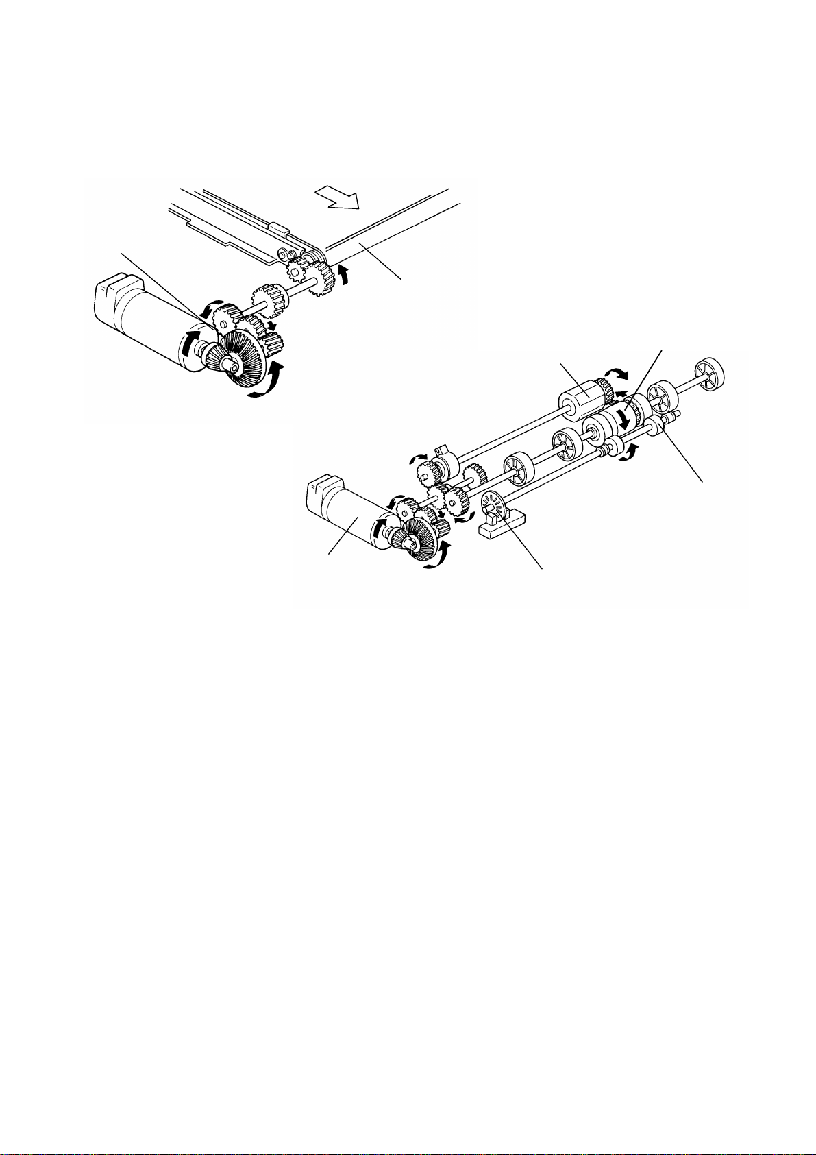
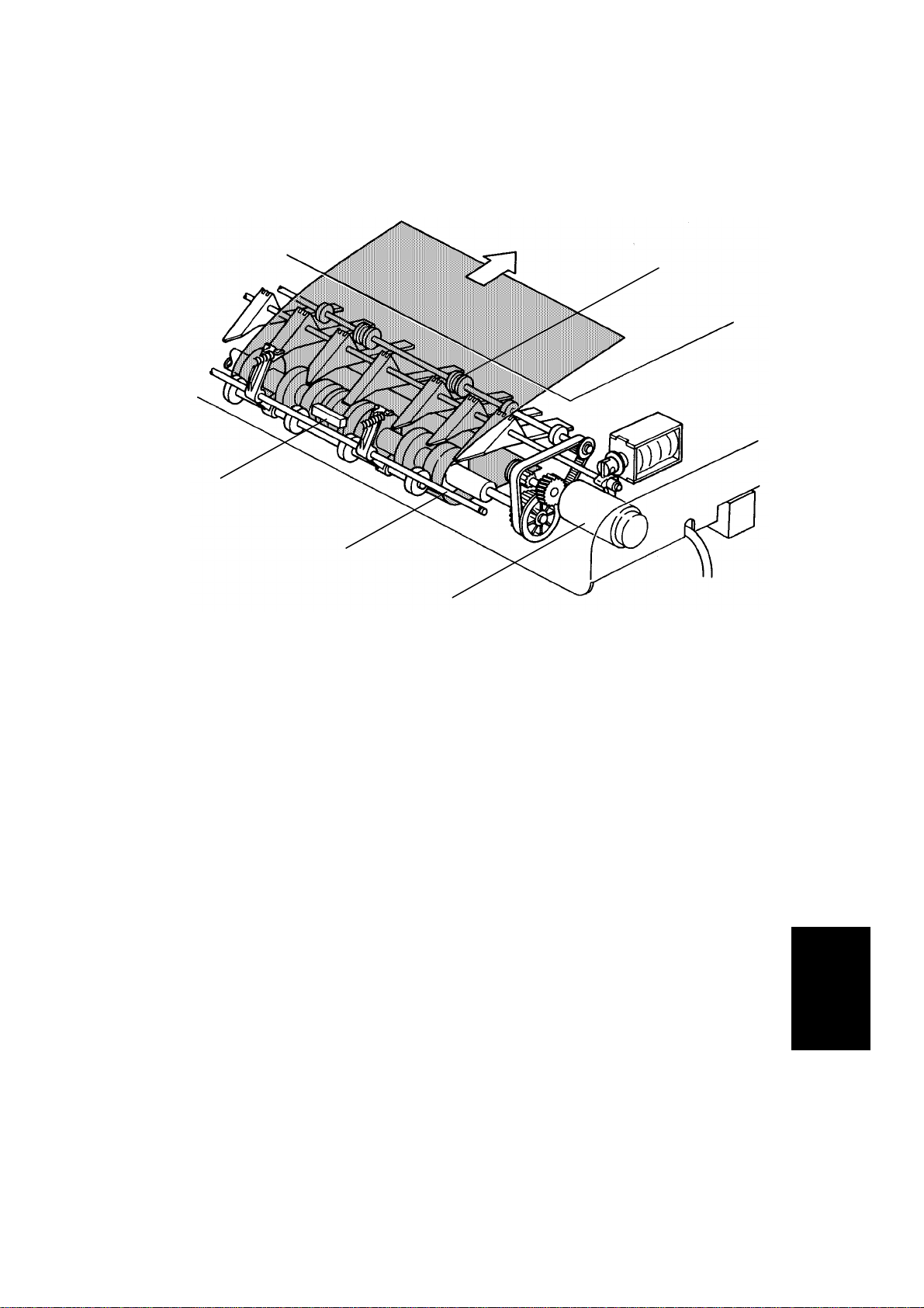
6.3 ORIGINAL FEED-IN MECHANISM
[D]
[F]
[C]
[B]
[A]
[F]
The belt drive motor [A] drives th e pick- u p rolle r [B] , th e fe ed roller [C], and
transport belt [D] via a feed clut ch an d a ge ar tr a in. And, the pull out roller [E]
is driven by friction with the feed ro ller.
[E]
The pick-up solenoid is energized 100 milliseconds after the Start key is
pressed. Then 100 milliseconds after the solenoid is energized, the belt drive
motor starts turning. The pulse generator disc [F] on the pull-out roller shaft
always turns when the belt drive motor is on in the forward direction.
238 encoder pulses of the belt drive motor after the original’s trailing edge
passes the registration sensor, the relay rollers and the transport belt stop
turning.
10

12 February 1992 ORIGINAL FEED
6.4 ORIGINAL SIZE DETECTION
[C]
[B]
[A]
The DF determines original size (both width and length) through the use of
the original width sensor [A, rear of DF], registration sensor [A, center of DF],
and pulse generator sensor [B]. The original’s length is calculated by
counting the number of pulses from the pulse generator [C] while the
registration sensor is on.
The original width sensor is turned on when the original width is 204 mm (8")
or more. It is in the same position (front to back) as the original width sensor
in the copier.
Original size detection is necessary for APS, AMS and the feed-in/feed-out
timing of the DF.
11
ARDF
ORIGINAL FEED 12 February 1992
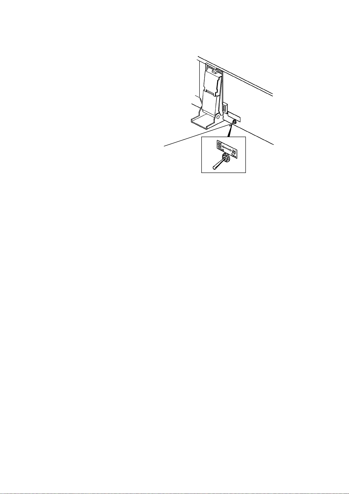
6.5 ORIGINAL SELECT SWITCH
[A]
This document feeder has two dif fe r en t ways of st op pin g orig inal at the
correct position on the exposur e gla ss. The y ar e calle d th e "thin original
mode" and the "thick orig inal mode". The mode used is det er m ined by the
original select switch [A].
1. Thin Original Mode
The original is stopped at the correct position on the exposure glass based
on encoder pulse count. For the first side of the original, the belt drive motor
stops 238 encoder pulses after the original’s trailing edge passes the
registration sensor in the one-sided original mode. For the reverse side of the
original, the belt drive motor reverses its rotation 85 m sec after the leading
edge passes the feed-out sens or. It stops after 2805 pulses. (Exact timing
depends on registration adjustment.) Thin original mode is selecte d at the
factory.
2. Thick Original Mode
When the thick original mode is selected, the original is aligned against the
original scale. For the first side, the belt drive motor stays on 36 encoder
pulses longer than when in the thin original mode, and then reverses for 62
encoder pulses. This forces the original against the original scale and thus
aligns the edge of the original with the original scale.
For the reverse side, the belt drive motor continues to reverse for 62 encoder
pulses longer than when in the thin original mode.
NOTE: The thick original mode should be used when the customer
requires more correct leading edge registration adjustment or
when these are complaints of skewed copies. The thin original
mode is to prevent the thin original’s from being bent since they
do not have great stiffness.
12
12 February 1992 ORIGINAL FEED
6.6 ORIGINAL INVERSION MECHANISM
[D]
[C]
The two sided originals are
inverted in the feed-out unit.
1) When the Start key is
pressed, the two sided original
is fed into the feed-in un it,
passing over the DF
registration sensor [A]. At the
same time, the feed-out motor
[B] starts turning
The inverter solenoid [C] turns
on 100 milliseconds after the
original’s trailing edge passes
the registration sensor
When the inverter solenoid
turns on, the inverter pawls [D]
rotate counterclockwise.
[B]
[D]
[A]
ARDF
13

ORIGINAL FEED 12 February 1992
2) The original passes over the
exposure glass [A] and feeds
into the feed-out unit.
[A]
3) The original is directed onto
the exposure glass again by
the inverter pawls. The belt
drive motor now reverses 85
milliseconds after the feed out
sensor [B] turns on. The
transport belt then moves the
original toward the original
scale.
When the original leading
edge reaches the original
scale, the belt drive motor
stops. At the same time, the
feed-out motor and the
inverter solenoid turn off.
4) After the reverse side of the
original is exposed, the belt
drive motor, the feed-out
motor, and the inver te r
solenoid turn on, and the
original is fed into the inverter
section. (This is the same as
step 2 above.)
[B]
5) The original is fed onto the
exposure glass again as in
step 3 above. The front side
of the original is then copied.
6) After the front side of the
original has been exposed, the
original is fed out from the DF.
14
12 February 1992 ORIGINAL FEED
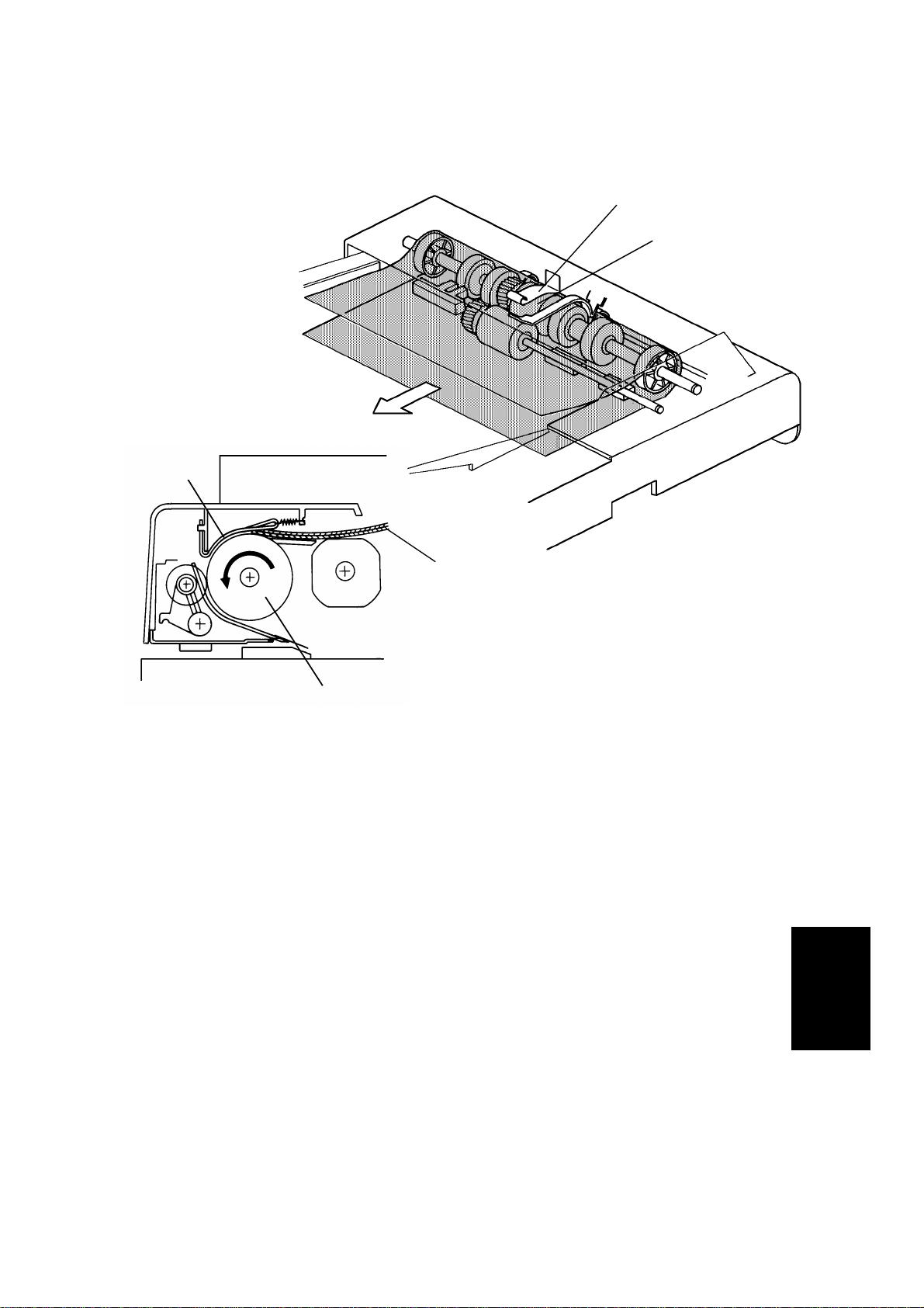
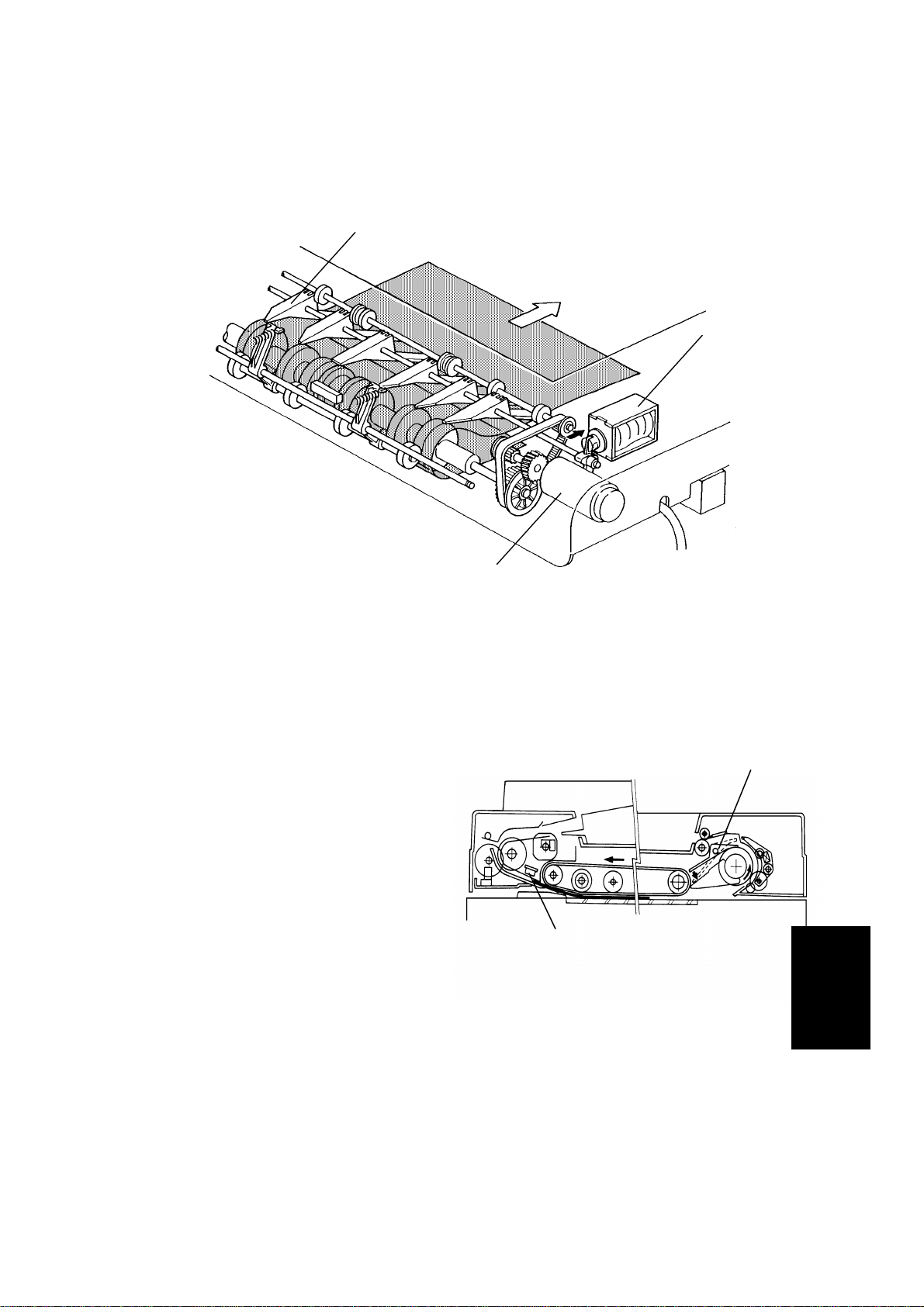
6.7 ORIGINAL FEED-OUT MECHANISM
[A]
[D]
[C]
[B]
The exit rollers [A] are driven by inverter motor [B]. When the document
feeder receives the feed out signal from the main system, the transport belt
and the exit rollers start turning simultaneously. The transport belt carries the
original to the inverter rollers [C] and the exit rollers take over the original
feed-out. When the original’s trailing edge passes the feed-out sensor [D], the
feed-out motor drops to half of its normal speed for 350 milliseconds and then
stops. The lower speed prevents uneven stacking of originals. For A3 or
double letter size originals, the feed-out motor speed does not change due to
the length of the originals.
ARDF
15
30 November 1990
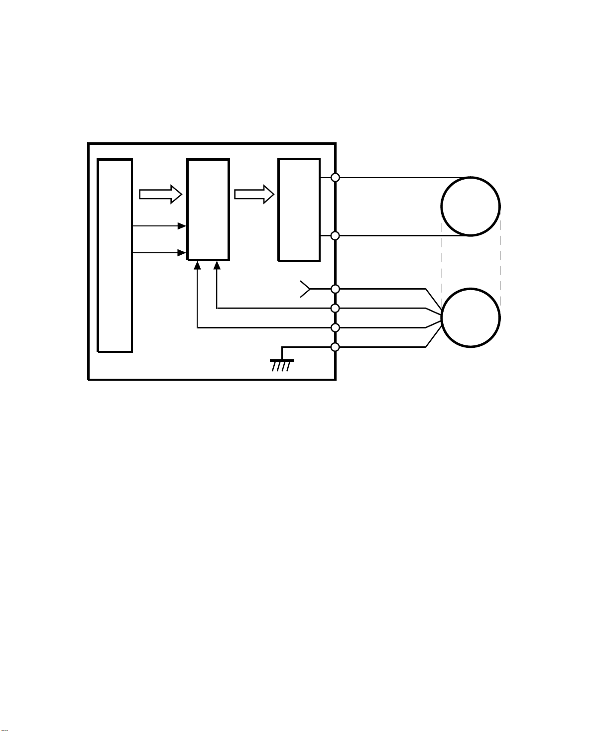
6.8BELT DRIVE MOTOR CIRCUIT
DF Main Board
CPU
Speed
Data
ON/OFF
Forward/
Reverse
Driver
IC
PWM
Driver
Circuit
+5V
Phase A
Phase B
CN102-1
CN102-2
CN103-1
CN103-2
CN103-3
CN103-4
Belt Drive
Motor
Encoder
A dc servomotor is used as the belt drive motor. The driver IC controls the
speed of the belt drive motor. The CPU sends the speed data (programmed) to
the driver IC. The driver IC sends the pulse-width-modulation (PWM) signal to
the driver circuit, which sends the motor drive pulses.
An encoder in the servomotor has two magnetic sensors that generate two
pulse signals (phase A and B ). The driver IC monitors the belt speed and direction by these pulse signals and uses this data to regulate the motor’s speed.
7-18
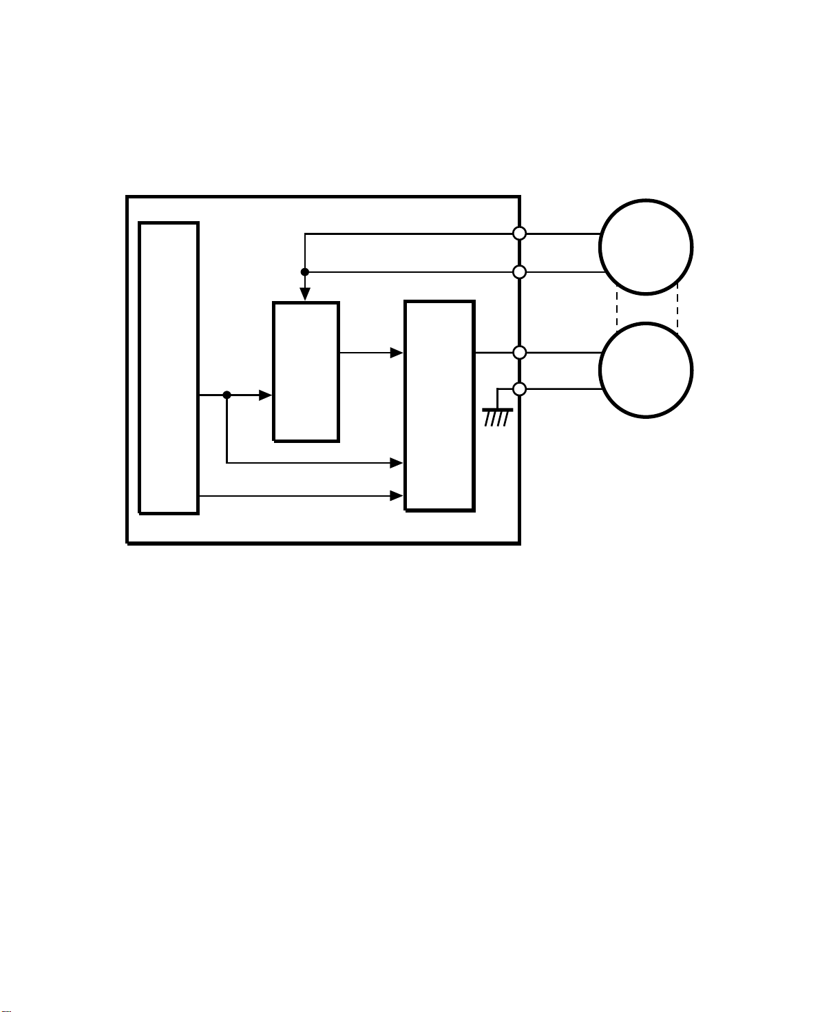
6.9FEED-OUT MOTOR CIRCUIT
DF Main Board
30 November 1990
CN104-A2
FG
CPU
High/Low
ON/OFF
Driver
IC
AC Feedback
Voltage
Regulation
Motor
Drive
Circuit
CN104-A15
CN104-B8
CN104-A12
Feed-out
Motor
The DF CPU sends the speed data (high or low) to the driver IC and the motor
drive circuit. The motor drive circuit creates the PWM signal and sends the motor drive pulses to the feed-out motor.
The frequency generator of the feed-out motor makes a very low voltage ac current which is fed back to the driver IC. The driver IC monitors the frequency of
this ac current and based on the frequency it regulates the motor speed.
7-19
LIFT MECHANISM 12 February 1992
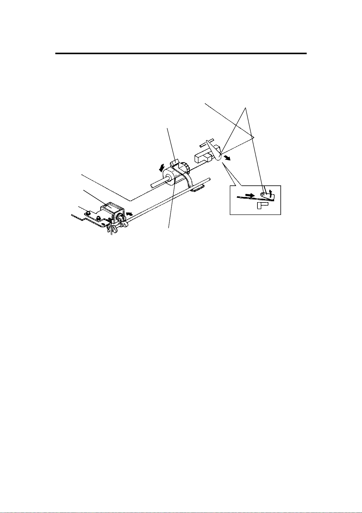
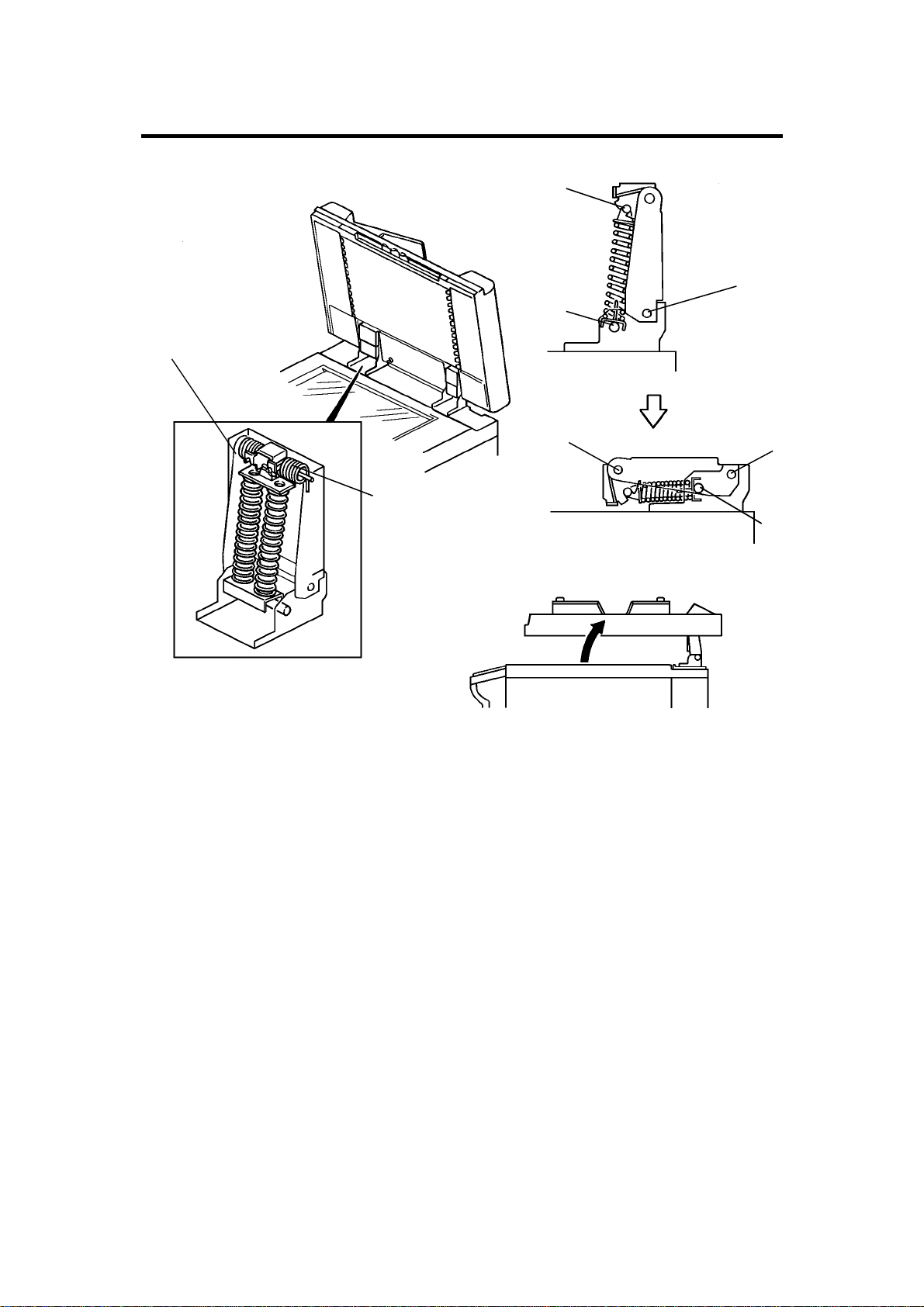
7. LIFT MECHANISM
[D]
[F]
[A]
[B]
[A]
[C]
[C]
[B]
[E]
When the document feeder is opened, the lift springs [D] provide enough
force to ensure that the document feeder does not fall onto the exposure
glass. When the document feeder is closed, points [A], [B], and [C] are
aligned and no such force is provided to the document feeder.
The lift switch is actuated when the document feeder is closed. The main
system then shifts to the document feeder mode. The lift switch also serves
as the reset switch for document feeder misfeeds.
When a book or thick original (maximum thickness 60 mm) is copied, the DF
acts as a cover for the original as shown in the figure [E]. The lift switch is
turned off during this condition, so the DF does not function. The tension of
spring [F] returns the DF to the normal condition after copying a thick original.
16

12 February 1992 ORIGINAL MISFEED SENSING
8. ORIGINAL MISFEED DETECTION
The main system’s CPU lights the original misfeed indicator if the previous
original remains on the exposure glass after manual copying and DF feed is
attempted. When the DF is lifted and the previous original is removed, DF
copying is permitted.
The registration sensor and the feed-out sensor are used for misfeed checks.
The functions of the two sensors are as follows:
8.1 ONE-SIDED ORIGINAL
Registration Sensor
ON check (540 ms)
Feed-out Sensor
OFF check (780 ms)
ON check (780 ms)
Belt Drive Motor
Feed-out Motor
OFF check (780 ms)
If the registration sensor is not actuated within 540 milliseconds after the belt
drive motor starts turning, the Original Misfeed indicator lights (ON check).
If the registration sensor does not turn off within 780 milliseconds, the CPU
determines that there has been an original misfeed (OFF check). The
Original Misfeed indicator also lights if the feed-out sensor is not actuated
within 780 milliseconds after the belt drive motor starts turning forward (ON
check), or if the feed-out sensor does not turn off within 780 milliseconds
after the feed-out sensor turns on (OFF check).
ARDF
17
 Loading...