

Ricoh df54 Service Manual

1. SPECIFICATIONS
Original Size and Weight: - Thin original mode -
Maximum A3 / 11" x 17"
Minimum B6 / 51/2" x 81/2"
Weight 41 to 128 g/m2 (11 to 34 lb)
- Thick original mode Maximum A3 / 11" x 17"
Minimum B6 / 51/2" x 81/2"
Weight 52 to 128 g/m2 (14 to 34 lb)
- Auto reverse mode Maximum A3 / 11" x 17"
Minimum B6 lengthwise /
51/2" x 81/2" lengthwise
Weight 64 to 105 g/m2 (17 to 28 lb)
Original Feed: Automatic feed — ADF mode
Manual feed one by one — SADF mode
1 January 1990
Original Table Capacity: 30 sheets / 80 g/m2 (20 lb)
Original Set: Face up. First sheet on top
Original Transport: One flat belt
Copy Speed: 12 copies/minute for A4 / 81/2" x 11" sideways
Power Consumption: 20 W
Dimensions (W x D x H): 670 x 460 x 103 mm (26.4" x 18.1" x 4.1")
Weight: Approximately 8.8 kg (19.4 lb)
7-1
1 January 1990
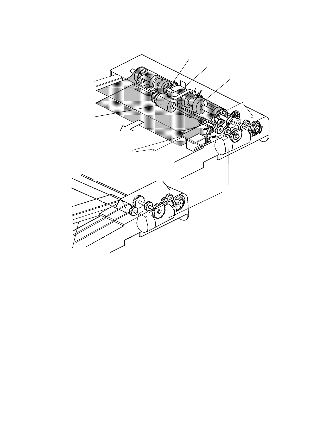
2. COMPONENT LAYOUT (NC100)
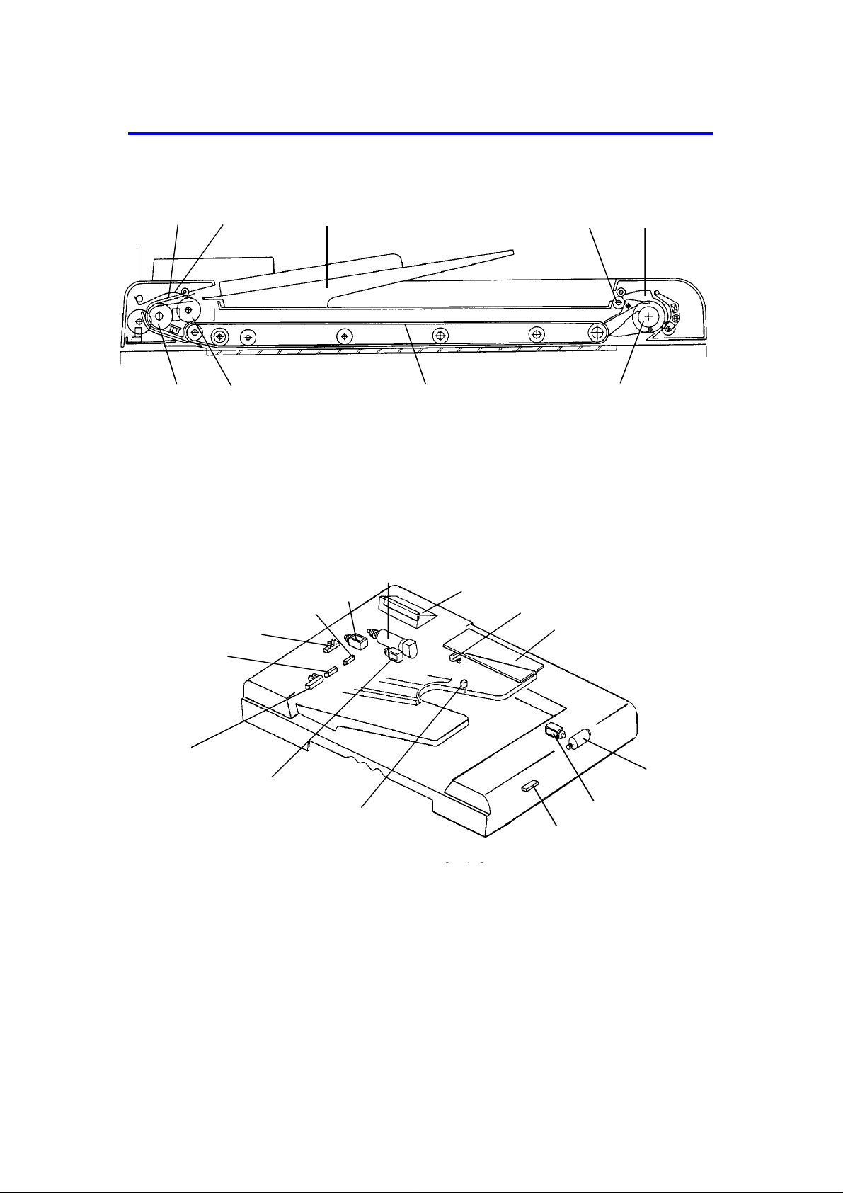
- Mechanical Components -
23
1
10
1. Pulse Generator Disk 6. Inverter Pawl
2. Friction Belt 7. Inverter Roller
3. Pick-up Lever 8. Transport Belt
4. Original Table 9. Pick-up Roller
5. Exit Roller 10. Feed Roller
- Electrical Components -
3
2
4
4
5
89
6
7
8
5
9
6
7
1
14
1. Original Set Sensor
2. Registration Sensor
3. Pulse Generator Sensor
4. Original Width Sensor
5. Pick-up Solenoid
6. Belt Drive Motor
7. Indicator Panel
13
10
11
12
8. Lift Switch
9. DF Main Board
10. Feed-out Motor
11. Inverter Solenoid
12. Feed-out Sensor
13. Original Select Switch
14. Feed-in Solenoid
7-2
1 August 1988
2. COMPONENT LAYOUT (FT2260)
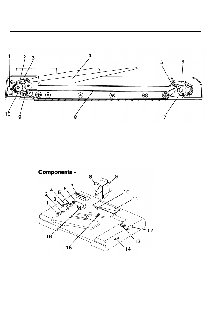
- Mechanical Components -
1. Pulse Generator Disk
2. Friction Belt
3. Pick-up Lever
4.
Original Table
5. Exit Roller
- Electrical
1. Original Set Sensor
2. Registration Sensor
3. Pulse Generator Sensor
4. Original Width Sensor
5. Pick-up Solenoid
6. Belt Drive Motor
7. Indicator Panel
8. Interface Board
6. Inverter Pawl
7.
Inverter Roller
8. Transport Belt
9. Pick-up Roller
10. Feed Roller
9. DF Power Supply Board
10. Lift Switch
11. DF Main Board
12. Feed-out Motor
13. Inverter Solenoid
14. Feed-out Sensor
15. Original Select Switch
16. Feed-in Solenoid
8-2

1 January 1990
3. ELECTRICAL COMPONENT DESCRIPTIONS
Symbol Name Function Location
Motors
M1 Belt Drive Motor DC servomotor that drives to the transport
belt and feed-in system (pick-up roller, feed
roller, pull-out roller and relay roller).
M2 Feed-out Motor DC servomotor that drives the feed-out unit
of the DF.
Solenoids
SOL1 Pick-up Solenoid Energizes to press the pick-up lever against
the stack of originals in preparation for original feed-in.
SOL2 Feed-in Solenoid Turns on to engage the feed-in clutch so ro-
tation is transmitted to the feed roller, pullout rollers, and relay rollers.
SOL3 Inverter Solenoid Energizes to invert the original when copy-
ing two sided originals.
Switches
SW1 Lift Switch Informs the CPU when the DF is lifted and
also serves as the jam reset switch for the
DF.
SW2 Original Select
Switch
Selects thick original mode or thin original
mode.
6
10
5
14
11
8
13
Sensors
S1 Original Set Sen-
sor
S2 Registration Sen-
sor
S3 Original Width
Sensor
S4 Pulse Generator
Sensor
S5 Feed-out Sensor Checks for original misfeeds and sets origi-
Informs copier CPU that originals have
been placed and causes the Insert Original
indicator to go out.
Sets original stop timing and measures original length.
Determines the width of the originals. 4
Generates pulses used to measure the original length.
nal stop timing when in auto reverse mode.
7-3
1
2
3
12

1 January 1990
Symbol Name Function Location
Printed Circuit Boards
PCB1 DF Main Board Controls all DF functions. 9
PCB2 Indicator Panel
Board
Contains operator indicators. 7
7-4
1 January 1990
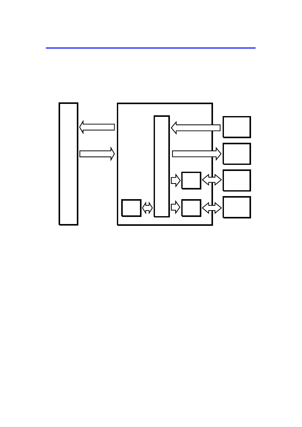
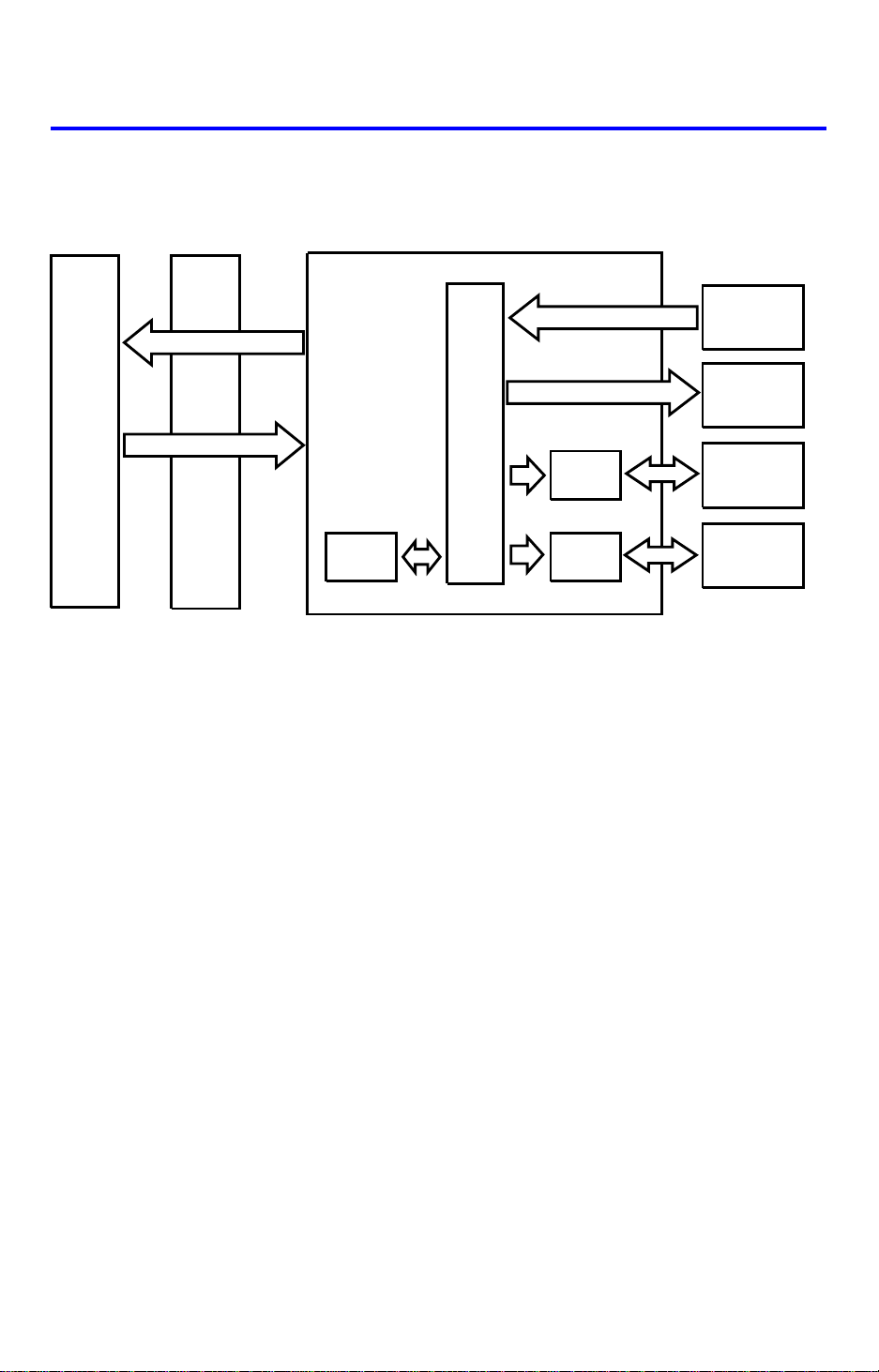
4. OVERALL MACHINE CONTROL (NC100)
Copier
Main PCB
DF Main Board
RXD
TXD
TXD
RXD
ROM
CPU
Driver
IC
Driver
IC
Sensors
Switches
Solenoids
Indicators
Belt Drive
Motor
Feed-out
Motor
The DF CPU monitors the input signals from the sensors and switch es, a nd
energizes the solenoids and the indicator LEDs directly. The belt drive motor
and the inverter motor are controlled by the DF CPU through their respective
driver ICs. The exchanged signals are shown in the tables on the next page.
7-5
1 August 1988
4. OVERALL MACHINE CONTROL (FT2260)
The DF CPU monitors the input signals from the sensors and switches, and
energizes the solenoids and the indicator LEDs directly. The belt drive motor
and the inverter motor are controlled by the DF CPU through their respective
driver ICs.
Also, the DF CPU communicates with the copier using a serial interface. The
exchanged signals are shown in the tables on the next page.
8-5
1 June 1990
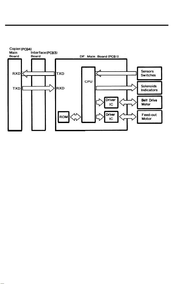
4. OVERALL MACHINE CONTROL (FT4418)
Copier (PCB1)
Main Board
RXD
TXD
Interface (PCB6)
Board
TXD
RXD
DF Main Board (PCB1)
ROM
CPU
Driver
IC
Driver
IC
Sensors
Switches
Solenoids
Indicators
Belt Drive
Motor
Feed-out
Motor
The DF CPU monitors the input signals from the sensors and switch es, a nd
energizes the solenoids and the indicator LEDs directly. The belt drive motor
and the inverter motor are controlled by the DF CPU through their respective
driver ICs. The exchanged signals are shown in the tables on the next page.
8-4

1 January 1990
1. DF → Copier
No. Signal Name Definition
1 Original Set Originals are set on the original table
2 Copy Start Allows the copier to start copy sequence
3 Lift Up The DF is lifted
4 DF Misfeed Misfeed occurs in the DF
2. Copier → DF
No. Signal Name Definition
1 Feed-in Reque sts th e DF to feed -in th e original
2 Feed-out Requests the DF to feed-ou t the original
3 Invert Original Requests the DF to invert the orig ina l
4 Auto Feed Shifts the DF to the auto feed mode
5 Original Stay
Attempt to use DF but the origina l from th e
previous copy run remains on th e exposure glass
7-6

1 January 1990
5. BASIC OPERATION
1. One-sided Original Feed
When an original is inserted face up into the DF, the Inse rt Orig inal indicator
light goes out and the DF informs the copier CPU that originals have been set.
When the Start key is pressed, the copier CPU moves the scanner 100 mm
away from the left scale an d sen ds the feed-in signal to the DF. On rece ipt of
this signal, the DF energizes the pick-up solenoid, the feed-in solenoid, and
the belt drive motor in order to feed-in the bottom sheet of the original sta ck
onto the exposure gla ss. The pick-up solenoid and the fee d-in solenoid
remain energized until the original leading edge rea che s the DF reg istra tio n
sensor. The belt drive motor turns off sho rtly af te r the origin al’s tra iling edge
passes the DF registration sen sor.
While feeding the original, the DF registra tio n sen sor and the paper width
sensor check the origina l size.
Just when the origina l trailing edge has passed the DF registra tion sensor,
the DF CPU sends the copy start signa l t o th e cop ier. On receipt of the
signal, the copier CPU carries out the origin al ID mea surement while
returning the scan ne r to the home position and starts th e copy cycle.
When the scanner reaches the return position, the copier CPU sends the
feed-out and the feed-in signals to the DF CPU in order to exchange the
original with the next original. At this time, the scanner be gin s retu rnin g to the
home position, but stays 100 mm away from th e lef t scale until the next
original is on the exposure gla ss. At this time the original ID measurement is
taken.
When the scanner comes to th e ret urn position after scanning the last
original, the copier CP U only sen ds the feed-out signal in ord er to feed-out
the last original.
7-7

1 January 1990
2. Two-sided Original Fee d
Unlike one-sided original feed, the back side of the original must be copied
first to keep the originals and copies in the correct order.
During original feed-in, the sequence is the same as fo r one-side d feed ;
however, the DF CPU also energizes the in vert er mot or an d th e inverter
solenoid a short time af te r t he origin al trailing edge has passed the DF
registration senso r. The be lt drive motor continues to fee d th e original until
the original leading ed ge passe s the fee d-o ut sensor. At this point th e
inverter mechanism inverts the origin al, in prep aration for copying the ba ck
side. Then the belt drive motor reverses and the original is fed towa rds th e
left scale and is aligned against the scale. The DF CPU sen ds th e copy st art
signal a short time afte r the origin al trailing edge has passed th e fe ed -out
sensor.
When the scanner reaches the return position, the copier CPU sends the
invert original signal to the DF CPU in order to make a copy of the front sid e.
The original is inverted in the same way as for back side copying.
3. Semi-automatic Document Feed
If a single original is inserte d int o the original table and cop ied, the DF shifts
to the semi-automatic feed mode and light s the Auto Fee d ind icat or. The
Auto Feed indicator remains on for five secon ds after the copier main motor
stops. If another origina l is inserted within that five-secon d period, it is
automatically fed and copied.
7-8
6. POWER DISTRIBUTION (NC100)
DF Main Board
CN808
1 January 1990
Copier
DC Power
PCB
CN101-3
+5V
+12V
Regulator
IC
The DF uses three DC power levels: +24 volts, +12 V, and +5 V.
The AC power from the wall outlet is supplied to t he DC power PCB o f th e
copier. The DC power PCB generates two DC voltages: +24V, +5V, and it
supplies power to the DF main board.
The regulator IC on the DF main board further steps down the +24V to +12V.
CN101-2
CN101-1
CN101-4
-4
-2
-1
-3
CN302-9
-10
304-8
301-14
GND
GND
[5]
[24]
~
7-9
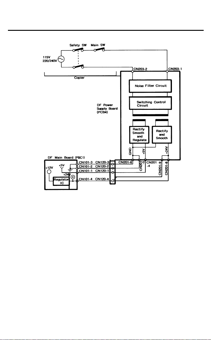
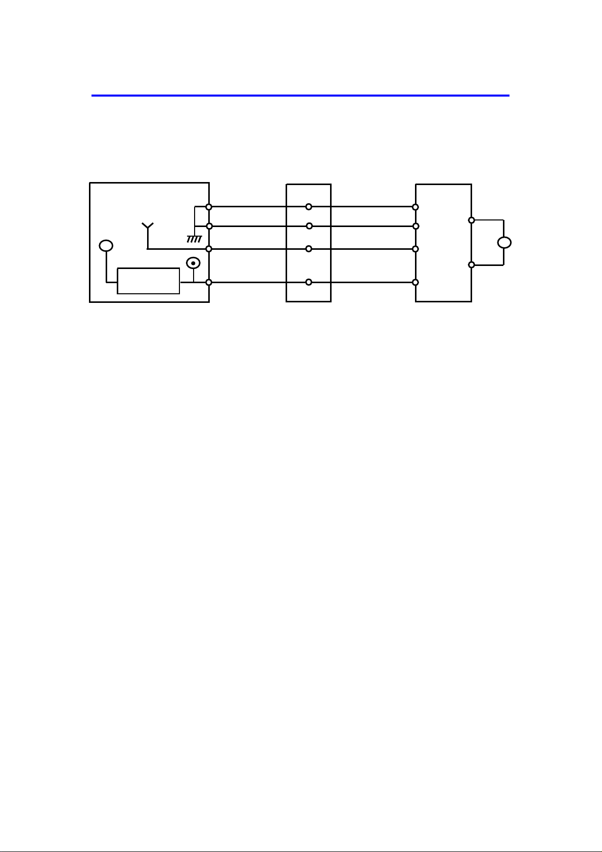
6. POWER DISTRIBUTION (FT2260)
1 August 1988
The DF uses three dc power levels: +24 volts, +12 volts, and +5 volts.
The line voltage is applied to the DF power supply board where it is stepped
down and rectified to +24 volts and +5 volts. Then, those two dc voltages
are supplied to the DF main board.
The regulator IC on the DF main board further steps down the +24 volts to
+12 volts.
8-9
1 June 1990
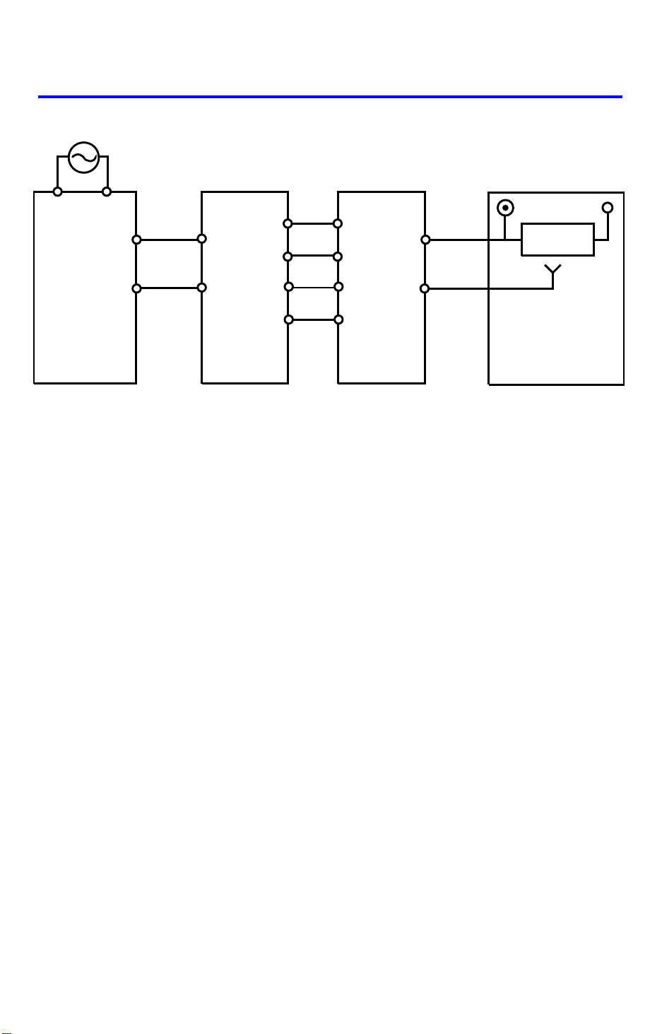
6. POWER DIST RIBUTION (FT4418)
AC Drive Board
(PCB2)
115Vac
220/240Vac
Optional
Transformer
(TR2)
26Vac
10Vac
Optional
DC Power
Supply Board
(PCB5)
+24V (VA)
+5V (VC)
+12V+24V
Regulator
IC
5V
DF Main Board
(PCB1)
The DF uses three DC power levels: +24 volts, +12 V, and +5 V.
When the main switch is turned on, the optional transformer receives the wall
outlet ac power through the ac drive board and outputs 10 volts ac and 26
volts ac to the optional dc power supply board. The optional dc power supply
board then converts the 10 volts ac input to +5 volts dc and the 26 volts ac
input to +24 volts. Then, thoes two dc voltsges are supplied to the DF main
board.
The regulator IC on the DF main board further steps down the +24V to +12V.
8-8
1 August 1988
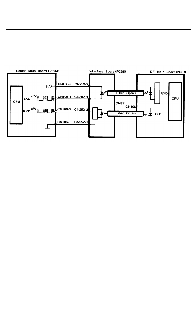
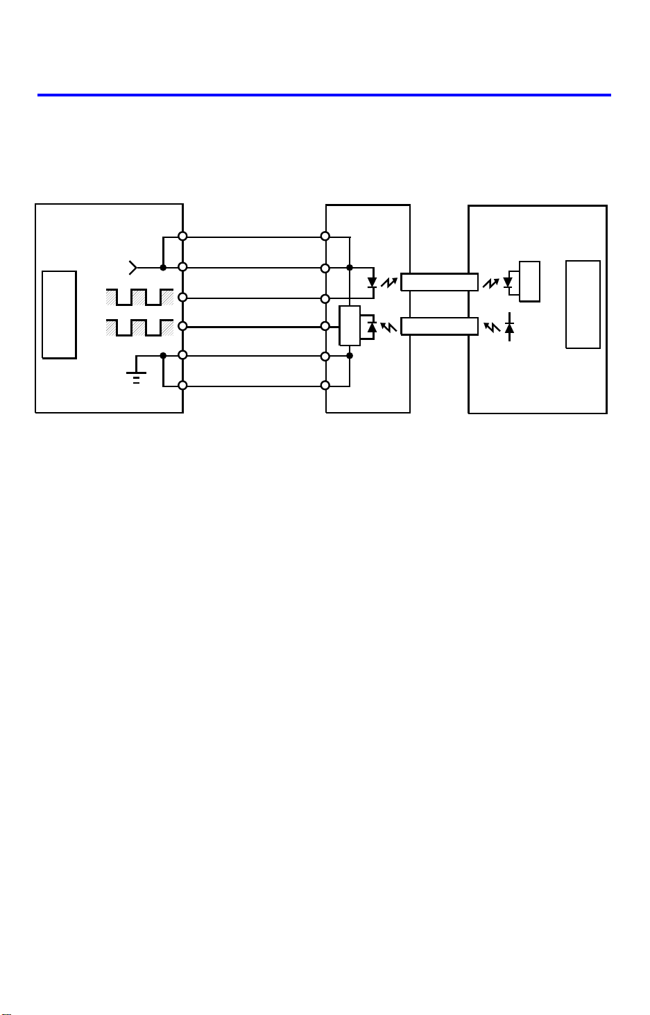
7. INTERFACE CIRCUIT (FT2260)
The Copier CPU and the DF CPU communicate via the interface board and
fiber optics. The interface board changes the optical signals to electrical signals (only vice versa).
8-10
7. INTERFACE CIRCUIT (FT4418)
1 June 1990
Copier Main Board (PCB1)
+5V CN206
+5V
TXD
CPU
+5V
RXD
CN133-A14
CN133-B14
CN106-4
CN106-3
CN133-A1
CN133-B1
Interface Board (PCB6) DF Main Board (PCB1)
CN201-A14
CN201-B14
CN201-A3
CN201-B3
CN201-A1
CN201-B1
Fiber Optics
Fiber Optics
CN106
TXD
RXD
The copier CPU and the DF CPU communicate via the interface b oa rd and
fiber optics. The interface board changes the optical signals to electrical
signals (and vice versa).
CPU
8-9
1 January 1990
7. ORIGINAL FEED
7.1 ORIGINAL PICK-UP
[C]
[A]
[B]
[D]
[A]
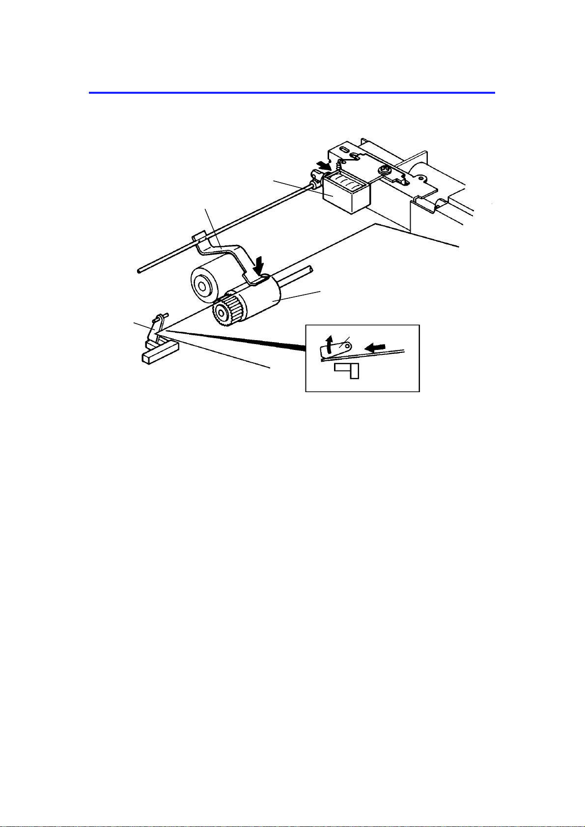
After setting the origina ls on th e orig ina l tab le, the origin als con ta ct th e feeler
[A] of the original se t sen sor an d cau se the feeler to move out of th e sensor.
The DF then sends the orig ina l set signal to the copier CPU to inf orm it th at
the DF will be used. When the Start key is presse d, the pick-up solenoid [B]
is energized. The original sta ck is then presse d between the pick-up lever [C]
and pick-up roller [D]. The rotation of the pick-up roller advances th e bo tt om
original.
7-10
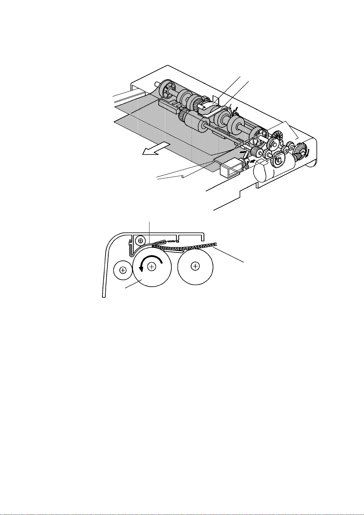
7.2 ORIGINAL SEPARATION
[B]
1 January 1990
[A]
[B]
[C]
[A]
The feed roller [A] and the friction belt [B] are use d to fee d-in and sepa rat e
the originals [C]. Only the bottom orig inal is fed because the friction belt
prevents any other origin als fro m f eeding.
Original feed starts when the feed roller starts turning and advances the
bottom original of the stack. The fee d roller mo ves th e original past the
friction belt because the driving force of the feed roller is great er than the
resistance of the frict ion belt . Th e frict ion belt prevents multiple feeds
because the resistance of the frict ion belt is great er th an the frictio n be twe en
original sheets.
7-11
1 January 1990
7.3 ORIGINAL FEED-IN MECHANISM
[B]
[E]
[C]
[D]
[A]
[F]
The belt drive motor [A] drives the pick-up roller [B], the feed ro ller [C] , the
pull out roller [D], the relay roller [E], and tra nsp ort belt [F] via a feed clutch
and a gear train.
The pick-up and feed-in soleno ids are ene rgize d 10 0 milliseco nd s aft er th e
Start key of the copier is pressed. Then 100 milliseconds afte r t he solen oids
are energized, the belt drive motor starts turning. The pulse gene rat or disc
[G] always turns when the belt drive motor is on.
Slightly after the original trailing edge passes the reg istra tio n sen sor, the
relay rollers and the transport belt sto p turnin g.
7-12
1 January 1990
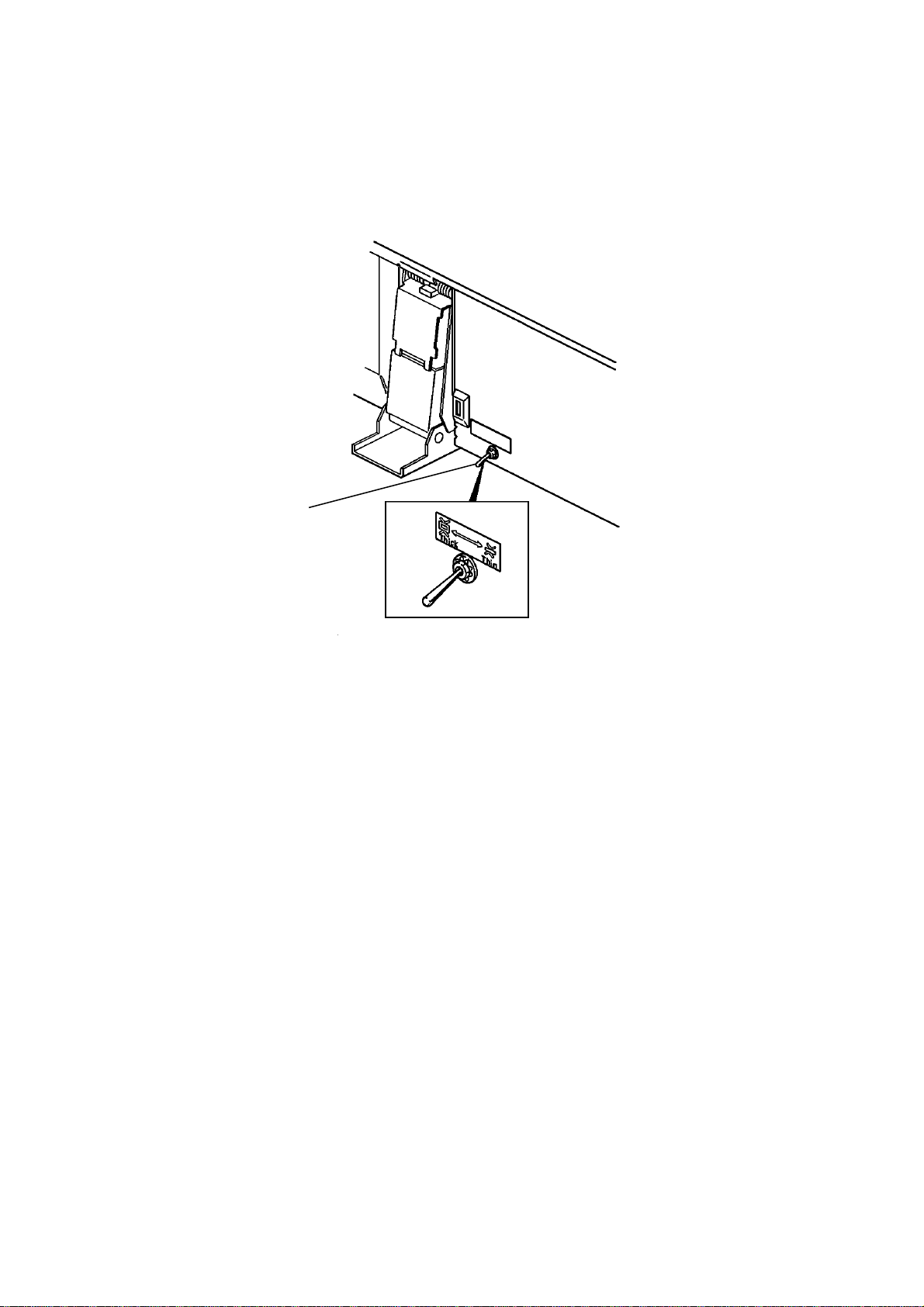
This document feed er ha s two dif ferent ways of stopping originals at the
correct position on the exposu re gla ss. They are called the "thin original
mode" and the "thick original mode". The mode used is dete rmine d by the
original select switch [A].
[A]
- Original Select Switch -
1. Thin Original Mode
The original is stopped at th e correct position on the exposure glass based
on encoder pulse count. The belt drive mo to r stop s short ly a ft er th e original
trailing edge passes the DF registra tio n sensor. (Exact timing depends on
registration adjustme nt.) Thin original mode is selected at the fact ory.
2. Thick Original Mode
When thick original mode is selecte d, the belt drive mot or rema ins en erg ized
for an additional 30 encod er pu lses as comp ared to thin original mode. Then,
the belt drive motor pauses and reverse s f or 21 pulse s. This f orce s the
original against the left scale and thu s align s the edge of the origin al with the
scale.
After the exposu re cycle is completed, the copier send s the fee d-out signal to
the DF CPU and the belt drive and feed out motors start turning. At this time ,
the copied original f ee ds out an d the next original feeds in.
7-13
1 January 1990
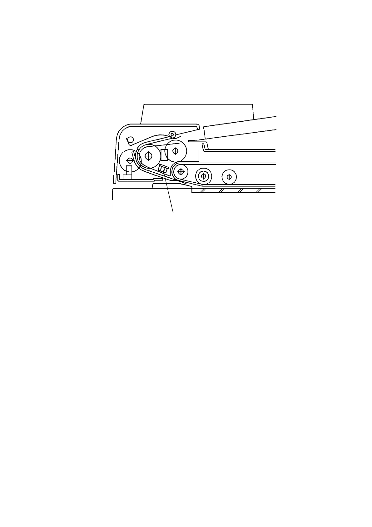
7.4 ORIGINAL SIZE DETECTI O N
[B]
[A]
The DF determines original size (bot h widt h and len gt h) th rou gh the use of
the original width sensor [A], registration sensor, and pulse gene rat or sen sor
[B]. The original’s length is calculated by countin g the numbe r of pulses fro m
the pulse generator while th e reg istration sensor is on.
Original size detection is necessary for the feed-in /feed-out timing of the DF.
7-14
 Loading...