

Ricoh D683, SPDF DF3080 Field Service Manual

SPDF DF3080
Machine Code: D683
Field Service Manual
July, 2014
Subject to change


Revision Lists
Version Section Details
1.00 -
Initial release of this document
Created this manual for D146 series.
1.10
All
Revised all sections according to the release
of D197 series
Modified some parts name.
Added the following sections:
> ADF Covers
> Document Feed Components
> Electrical Components
> Original Feed Drive
Read This First > Safety and Symbols Modified some icons.
Replacement and Adjustment > ADF
Removal
Modified Step 1 through Step 6.
Replacement and Adjustment >
Platen Adjustment
Changed the name for fastener in Step 3.
Replacement and Adjustment > ADF
Covers > ADF Rear Cover
Modified items need to be removed in Step
3.
Replacement and Adjustment >
Document Feed Components >
Original Feed Unit
Modified Step 3.
Replacement and Adjustment >
Document Feed Components > Pickup Roller / Transport Belt
Added a Note for Step 2.
Replacement and Adjustment >
Document Feed Components >
White Roller
Added this section.
Replacement and Adjustment >
Electrical Components > CIS Unit
Modified the procedure.
1

Version Section Details
Replacement and Adjustment >
Electrical Components > ADF Pickup Roller Lift Motor / ADF Transport
Motor
Added item needs to be removed in Step 2.
Replacement and Adjustment >
Electrical Components > Original
Registration Sensor
Deleted unnecessary part in Step 4.
Replacement and Adjustment >
Electrical Components > Original
Exit Sensor
Added new steps into Step 1 and Step 2.
Modified the description of Step 5.
Replacement and Adjustment >
Electrical Components > Separation
Sensor / Skew Correction Sensor
Deleted some steps.
Replacement and Adjustment >
Electrical Components > Original
Set Sensor
Replacement and Adjustment >
Electrical Components > A4 LEF/LT
LEF Sensor
Replacement and Adjustment >
Original Feed Drive > ADF Entrance
Motor
Modified the procedure.
Replacement and Adjustment >
Original Feed Drive > ADF Exit
Motor
Added Step 3.
Replacement and Adjustment >
Original Feed Drive > ADF Feed
Motor
Modified Step 2 and its picture.
2
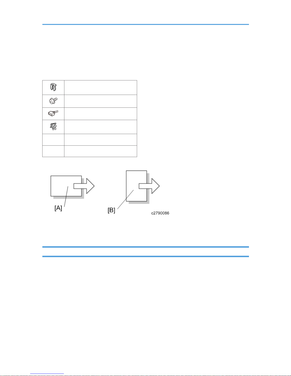
Safety and Symbols
This manual uses several symbols and abbreviations. The meaning of those symbols and abbreviations
are as follows:
Clip ring
Screw
Connector
Clamp
SEF Short Edge Feed
LEF Long Edge Feed
[A] Short Edge Feed (SEF)
[B] Long Edge Feed (LEF)
Trademarks
Microsoft®, Windows®, and MS-DOS® are registered trademarks of Microsoft Corporation in the
United States and /or other countries.
PostScript® is a registered trademark of Adobe Systems, Incorporated.
PCL® is a registered trademark of Hewlett-Packard Company.
Ethernet® is a registered trademark of Xerox Corporation.
PowerPC® is a registered trademark of International Business Machines Corporation.
Other product names used herein are for identification purposes only and may be trademarks of their
respective companies. We disclaim any and all rights involved with those marks.
3

TABLE OF CONTENTS
Revision Lists........................................................................................................................................................1
Safety and Symbols............................................................................................................................................3
Trademarks.....................................................................................................................................................3
1. Replacement and Adjustment
ADF Removal......................................................................................................................................................7
Adjustment after Replacing the ADF...............................................................................................................11
CIS RGB Adjustment ...................................................................................................................................11
Checking the vertical registration...............................................................................................................11
Checking the horizontal registration..........................................................................................................12
Checking the skew.......................................................................................................................................12
Checking the magnification.........................................................................................................................12
Platen Adjustment.............................................................................................................................................13
ADF Covers.......................................................................................................................................................15
ADF Front Cover..........................................................................................................................................15
ADF Rear Cover...........................................................................................................................................16
Feed Cover...................................................................................................................................................17
Document Feed Components..........................................................................................................................19
Original Feed Unit.......................................................................................................................................19
Pick-up Roller / Transport Belt....................................................................................................................19
ADF Separation Roller.................................................................................................................................22
White Roller..................................................................................................................................................23
Electrical Components.....................................................................................................................................28
CIS Unit.........................................................................................................................................................28
ADF Pick-up Roller Lift Motor / ADF Transport Motor.............................................................................30
ADF Bottom Plate Lift Motor........................................................................................................................31
Original Registration Sensor.......................................................................................................................32
Original Exit Sensor.....................................................................................................................................33
ADF Control Board......................................................................................................................................36
Separation Sensor / Skew Correction Sensor..........................................................................................36
Original Width Sensor / Interval Sensor...................................................................................................37
B5 Width Sensor / A4 Width Sensor / LG Width Sensor......................................................................39
APS Feeler....................................................................................................................................................39
ADF Lift-Up Interlock SW / Lift-Up Sensor................................................................................................40
4

Original Set Sensor......................................................................................................................................41
A4 LEF/LT LEF Sensor..................................................................................................................................42
Bottom Plate HP Sensor...............................................................................................................................42
Bottom Plate Position Sensor.......................................................................................................................43
ADF Feed Cover Interlock Switch / Pick-up Roller HP Sensor.................................................................
44
Original Feed Drive.........................................................................................................................................46
ADF Entrance Motor....................................................................................................................................46
ADF Scanning Motor...................................................................................................................................46
ADF Exit Motor.............................................................................................................................................47
ADF Feed Motor..........................................................................................................................................48
5

6

1. Replacement and Adjustment
ADF Removal
1. Controller cover [A] ( ×4).
2. Controller rear cover [A] ( ×4)
7
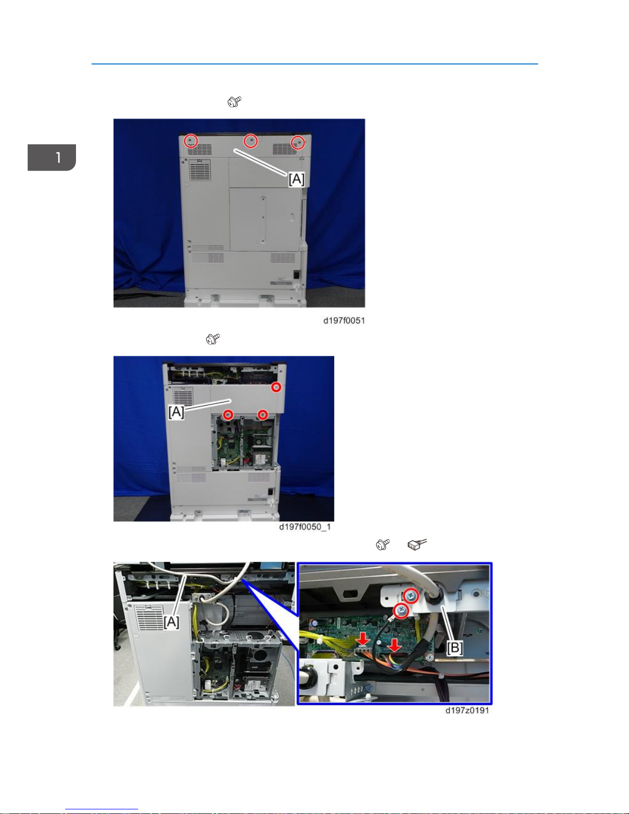
3. Scanner rear cover [A] ( ×3)
4. Rear left cover [A] ( ×3)
5. Disconnect the I/F cable [A] along with the bracket [B] ( ×2, ×2).
1. Replacement and Adjustment
8
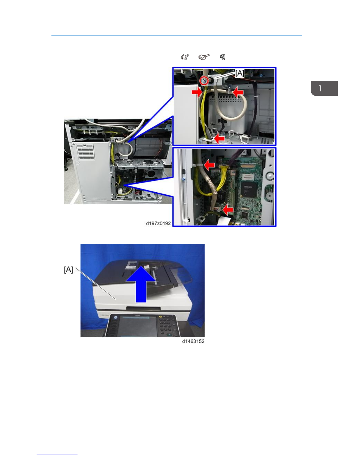
6. CIS image cable along with the bracket [A] ( ×1, ×1, ×4).
7. Open the ADF [A].
ADF Removal
9
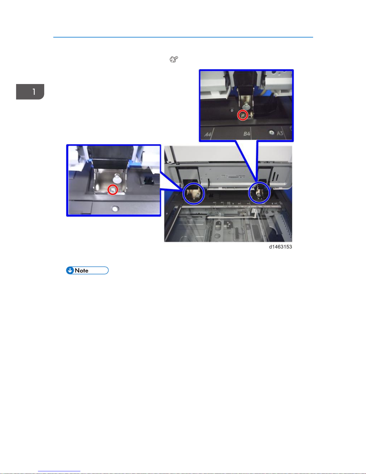
8. Remove the fixing screws of the ADF ( ×2).
9. While holding the left and right sides of the ADF, lift up to remove it.
• Because of the weight of the ADF, handle with care.
1. Replacement and Adjustment
10
Adjustment after Replacing the ADF
CIS RGB Adjustment
Enter the four-digit numeric values for RGB that are listed on the paper that comes with the ADF into the
following SP.
R: SP4-712-001 (CIS GB Adj Value: R)
G: SP4-713-001 (CIS GB Adj Value: G)
B: SP4-714-001 (CIS GB Adj Value: B)
Checking the vertical registration
SP6-006-001 (ADF Adjustment Side-to-Side Regist: Front)
SP6-006-002 (ADF Adjustment Side-to-Side Regist: Rear)
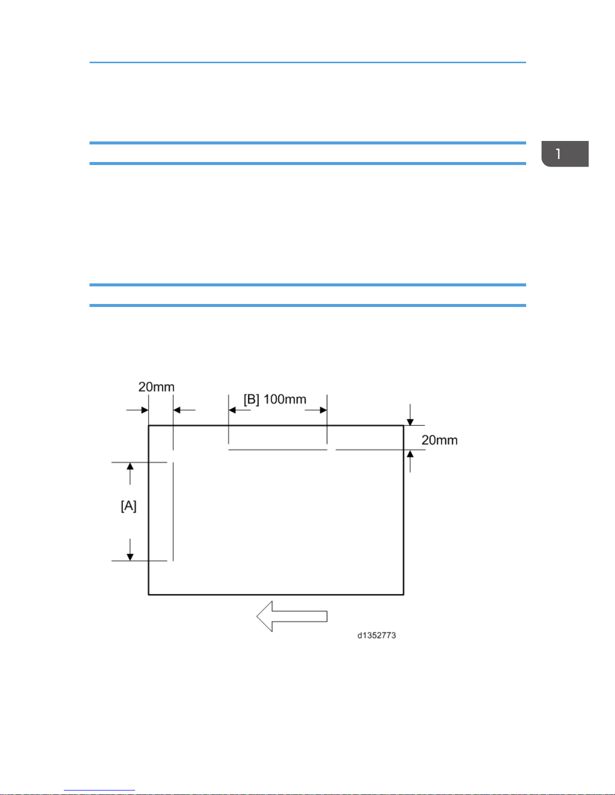
1.
Create an original as shown in the following picture.
*The arrows indicate the direction of feed.
2.
Copy the original and make sure that the position of the line [A] is within 0±1mm
3. If not within the standard, adjust with the SP modes.
Adjustment after Replacing the ADF
11
Checking the horizontal registration
SP6-006-010 (ADF Adjustment L-Edge Regist (1-Pass): Front)
SP6-006-011 (ADF Adjustment L-Edge Regist (1-Pass): Rear)
1.
Copy the original and make sure that the position of the line [B] is within 0±2mm.
2. If not within the standard, adjust with the SP modes.
Checking the skew
SP6-006-012 (ADF Adjustment 1st Buckle (1-Pass))
SP6-006-013 (ADF Adjustment 2nd Buckle (1-Pass))
1.
Make sure that the difference between both end positions of the line [A] is within 0±2mm.
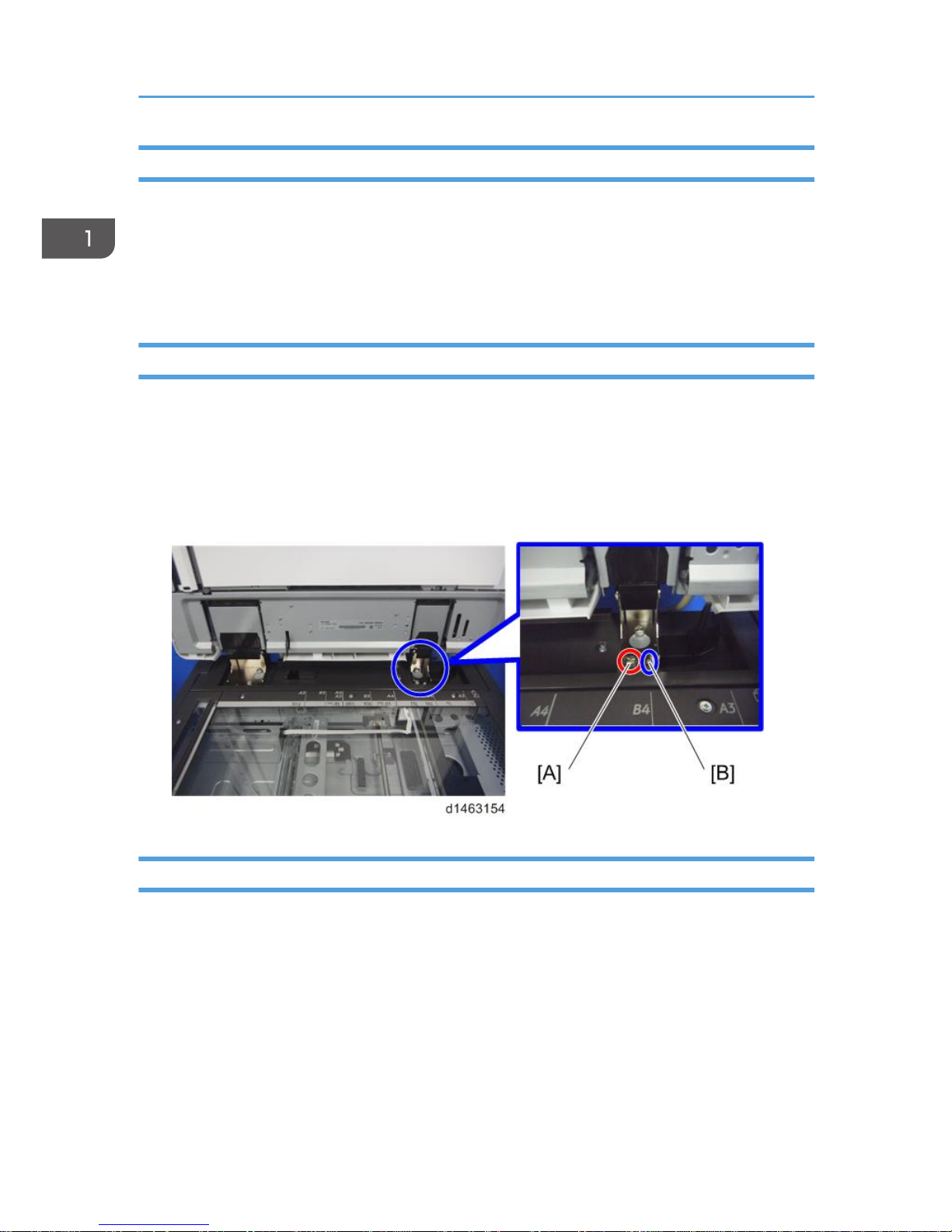
2. If not within the standard, change the position of the fixing screw [A] to the long hole [B] at the right
hinge.
Checking the magnification
SP6-017-001 (DF Magnification Adj.)
1.
Copy the original and make sure that the length of the line [B] is within 100±1mm.
2. If not within the standard, adjust with the SP mode.
1. Replacement and Adjustment
12
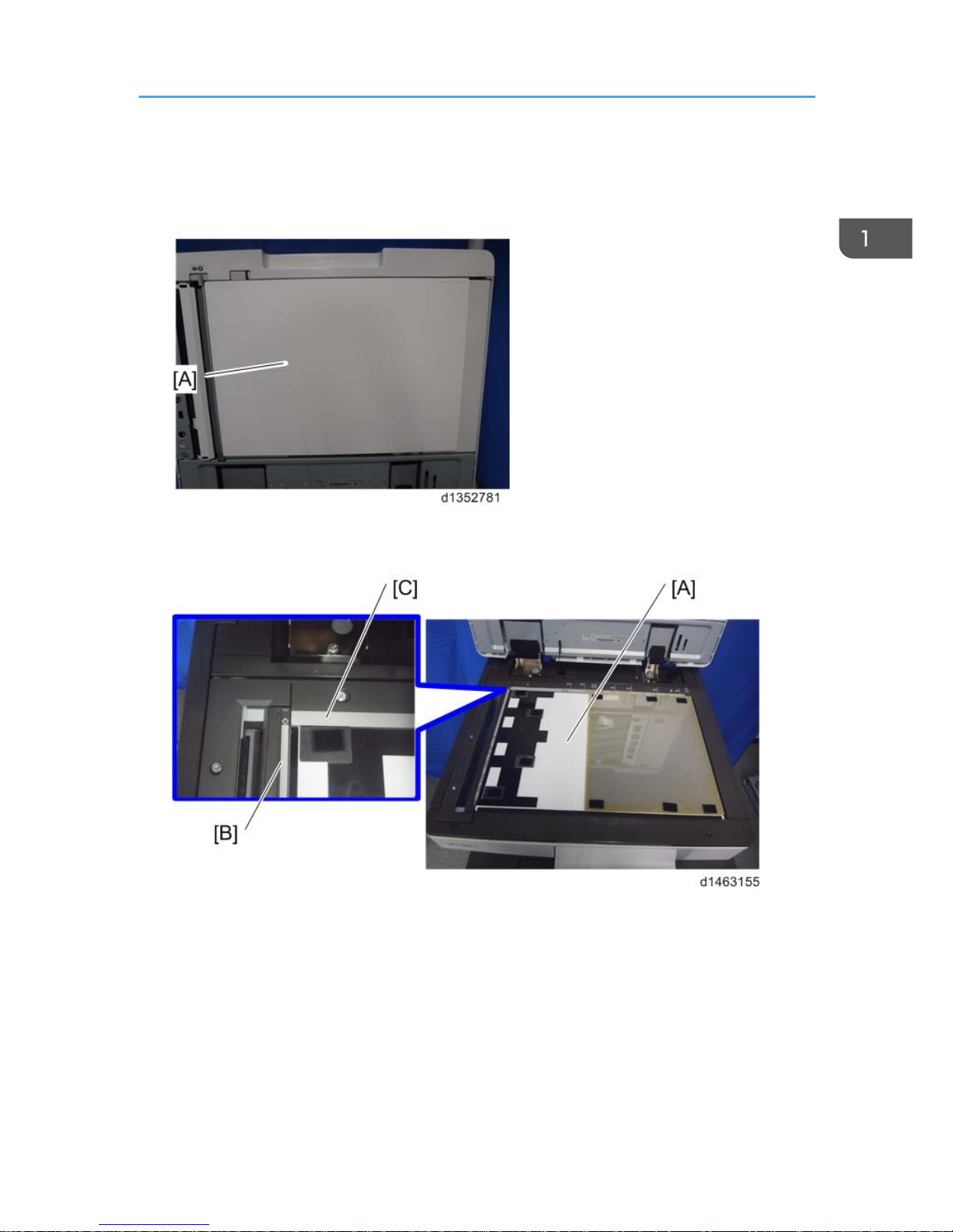
Platen Adjustment
1. Open the ADF and remove the white cover (fabric fastener × 10).
2. Put the white cover [A] in the correct position on the exposure glass, aligning it with the
glass cover [B] and the rear scale [C].
Platen Adjustment
13
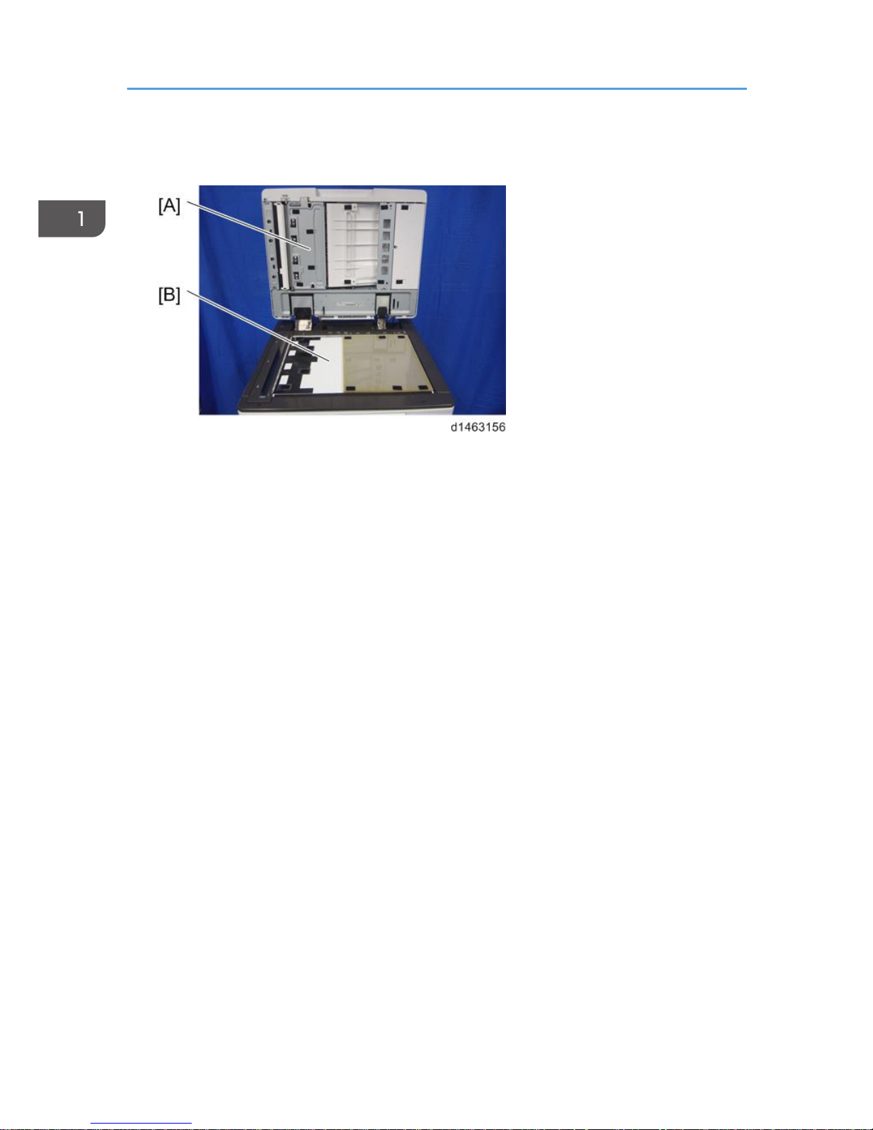
3. Close the ADF [A] slowly and paste the ADF and the white cover [B] with the fabric
fastener.
1. Replacement and Adjustment
14
ADF Covers
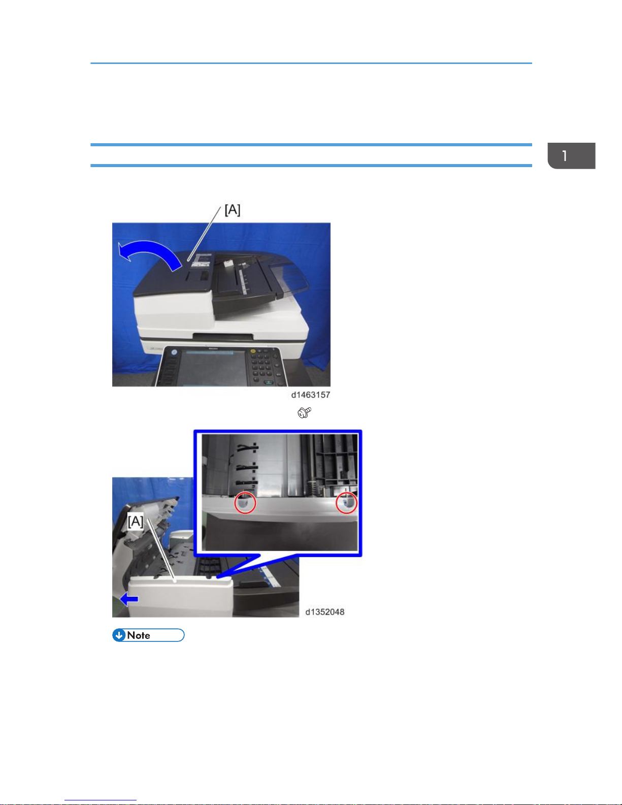
ADF Front Cover
1. Open the feed cover [A].
2. Slide the ADF front cover [A] to the left ( ×2, hook×4).
• Check the position of the hooks in the photo below before removing.
ADF Covers
15
 Loading...