

Ricoh D3D9 Field Service Manual

FAX Option Type M26
Machine Code: D3D9
Field Service Manual
Ver 1.0
Latest Release: Oct, 2016
Initial Release: Oct, 2016
Copyright (c) 2016 Ricoh Co.,Ltd.

Symbols, Abbreviations
This manual uses several symbols and abbreviations. The meaning of those symbols and abbreviations are as
follows:
Symbol What it means
Clip ring
Screw
Connector
Clamp
E-ring
Flat Flexible Cable
Timing Belt
SEF Short Edge Feed
LEF Long Edge Feed
K Black
C Cyan
M Magenta
Y Yellow
B/W, BW Black and White
FC Full color
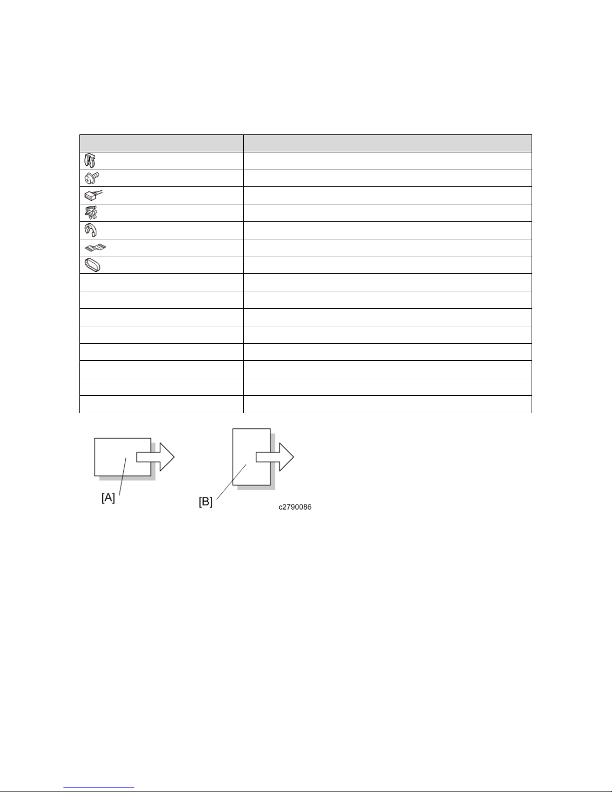
[A] Short Edge Feed (SEF)
[B] Long Edge Feed (LEF)


1
Table of Contents
1. Installation .......................................................................................................................................................... 4
Fax Option Type M26 (D3D9) .............................................................................................................................. 4
Accessory Check ............................................................................................................................................... 4
Installation Procedure ........................................................................................................................................ 4
G3 Interface Unit Type M26 (D3D9-07, -08, -12) .............................................................................................. 15
Accessory Check ............................................................................................................................................. 15
Installation Procedure ...................................................................................................................................... 15
Notes for Connecting the Telephone Line....................................................................................................... 22
Fax Unit Options ................................................................................................................................................. 24
Fax Memory Unit Type M26 64MB (D3D9) .................................................................................................. 24
Fax Connection Unit Type M26 (D3D8-01, 02, 03) ........................................................................................... 27
Accessory Check ............................................................................................................................................. 27
Installation Procedure ...................................................................................................................................... 27
2. Replacement and Adjustment ........................................................................................................................... 31
FCU ..................................................................................................................................................................... 31
FCU ................................................................................................................................................................. 31
3. Troubleshooting ............................................................................................................................................... 39
Error Codes .......................................................................................................................................................... 39
Error Codes ..................................................................................................................................................... 39
Fax Connection Unit Error Codes ....................................................................................................................... 55
Fax Connection Unit Error Code List ............................................................................................................. 55
IFAX Troubleshooting ........................................................................................................................................ 57
IFAX Troubleshooting .................................................................................................................................... 57
IP-Fax Troubleshooting ....................................................................................................................................... 59
IP-Fax Transmission ....................................................................................................................................... 59
IP-Fax Reception ............................................................................................................................................. 61
4. Service Tables .................................................................................................................................................. 64
Cautions ............................................................................................................................................................... 64
Service Program Tables ....................................................................................................................................... 65
SP1-XXX (BIT Switches) ............................................................................................................................... 65
SP2-XXX (RAM) ............................................................................................................................................ 65
SP3-XXX (Machine Set) ................................................................................................................................. 66
SP4-XXX (ROM Versions) ............................................................................................................................ 68
SP5-XXX (RAM Clear) .................................................................................................................................. 68
SP6-XXX (Reports) ........................................................................................................................................ 68
SP7-XXX (Tests) ............................................................................................................................................ 70
Bit Switches – 1 ................................................................................................................................................... 72

2
System Switches .............................................................................................................................................. 72
Bit Switches – 2 ................................................................................................................................................... 83
I-Fax Switches ................................................................................................................................................. 83
Printer Switches .............................................................................................................................................. 88
Bit Switches – 3 ................................................................................................................................................... 94
Communication Switches ................................................................................................................................ 94
Bit Switches – 4 ................................................................................................................................................. 102
G3 Switches .................................................................................................................................................. 102
Bit Switches – 5 ................................................................................................................................................. 110
G3-2 and G3-3 Switches ............................................................................................................................... 110
G4 Internal Switches ..................................................................................................................................... 116
G4 Parameter Switches ................................................................................................................................. 116
Bit Switches – 6 ................................................................................................................................................. 117
IP Fax Switches ............................................................................................................................................. 117
NCU Parameters ................................................................................................................................................ 124
NCU Parameters ............................................................................................................................................ 124
Dedicated Transmission Parameters .................................................................................................................. 135
Programming Procedure ................................................................................................................................ 135
Parameters ..................................................................................................................................................... 135
Service RAM Addresses .................................................................................................................................... 142
Service RAM Addresses ............................................................................................................................... 142
5. Detailed Section Descriptions ........................................................................................................................ 154
Overview ........................................................................................................................................................... 154
Overview ....................................................................................................................................................... 154
Boards ................................................................................................................................................................ 155
FCU ............................................................................................................................................................... 155
SG3 Board ..................................................................................................................................................... 156
Video Data Path ................................................................................................................................................. 158
Transmission ................................................................................................................................................. 158
Reception ....................................................................................................................................................... 160
Fax Communication Features ............................................................................................................................ 161
Multi-port ...................................................................................................................................................... 161
Document Server ........................................................................................................................................... 161
Internet Mail Communication ....................................................................................................................... 162
IP-Fax ................................................................................................................................................................ 170
What is IP-FAX? ........................................................................................................................................... 170
T.38 Packet Format ....................................................................................................................................... 170
Settings .......................................................................................................................................................... 170
6. Specifications ................................................................................................................................................. 171

3
General Specifications ....................................................................................................................................... 171
FCU ............................................................................................................................................................... 171
Capabilities of Programmable Items ................................................................................................................. 173
Capabilities of Programmable Items ............................................................................................................. 173
IFAX Specifications .......................................................................................................................................... 174
IFAX Specifications ...................................................................................................................................... 174
IP-FAX Specifications....................................................................................................................................... 176
IP-FAX Specifications .................................................................................................................................. 176
Fax Unit Configuration...................................................................................................................................... 177
1.Installation
4
1. Installation
Fax Option Type M26 (D3D9)
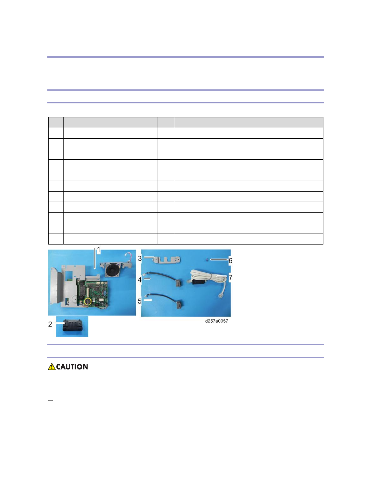
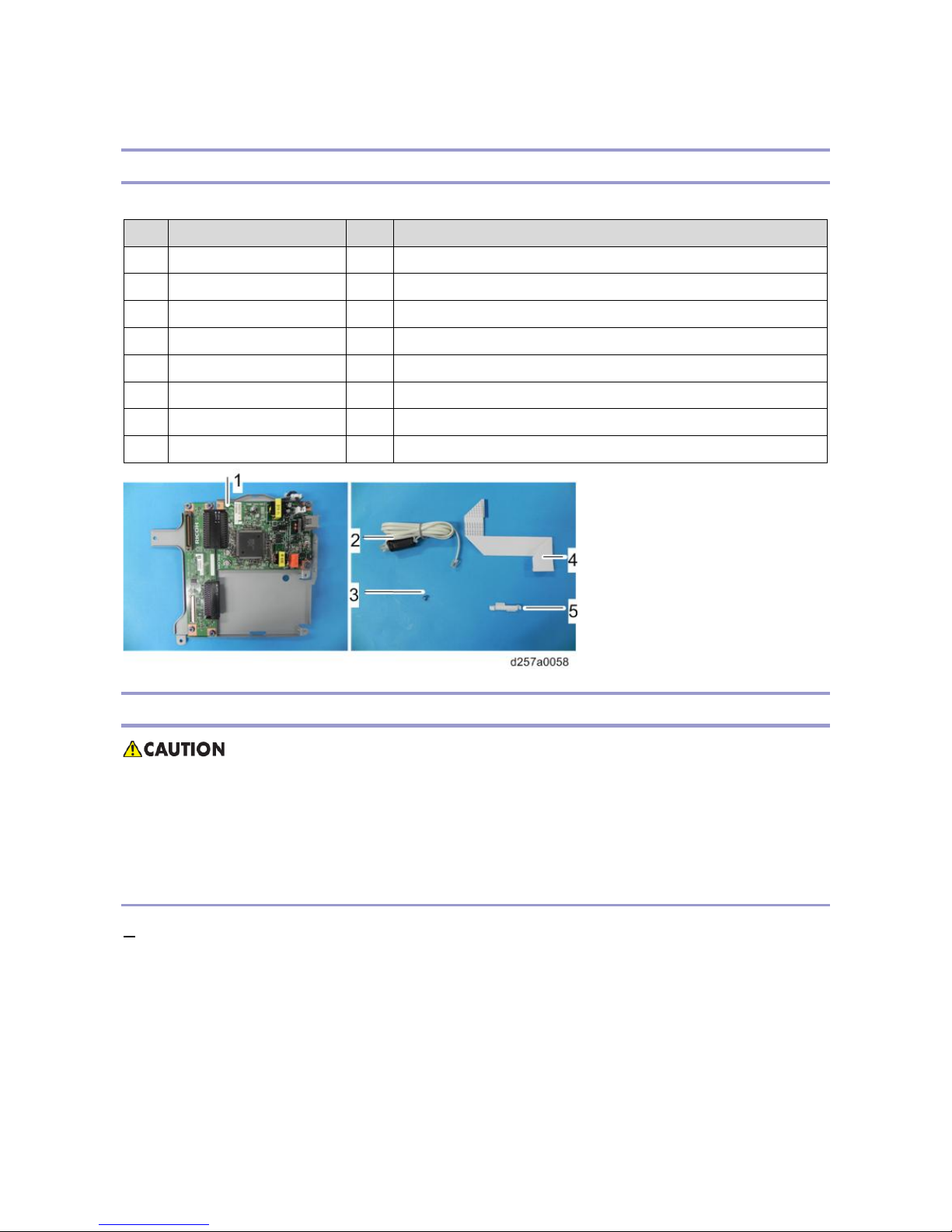
Accessory Check
Check the quantity and condition of th e accessories against the following list.
No. Description Q'ty Remarks
1 FCU 1
2 CONNECTOR:FX18-40PS-0.8H15 1
3 Modular Bracket 1
4 Harness: TEL 1
5 Harness: LINE 1
6 Screw: M3x6 8
7 Telephone Cable 1 NA only
7 Ferrite Core 1 For NA, this ferrite core is attached to the telephone cable.
- S er ial number decal 1
- E MC Address Decal 1 EU only
- FCC Decal 1 NA only
Installation Procedure
• Before installing this fax unit, print out all data in the printer buffer. Turn the main power to OFF and
disconnect the power cord and the network cable.
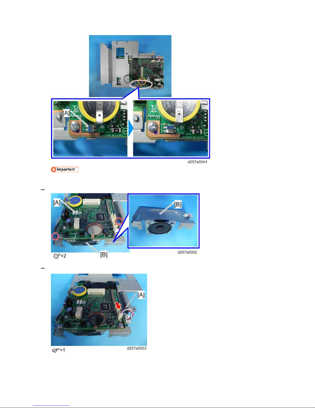
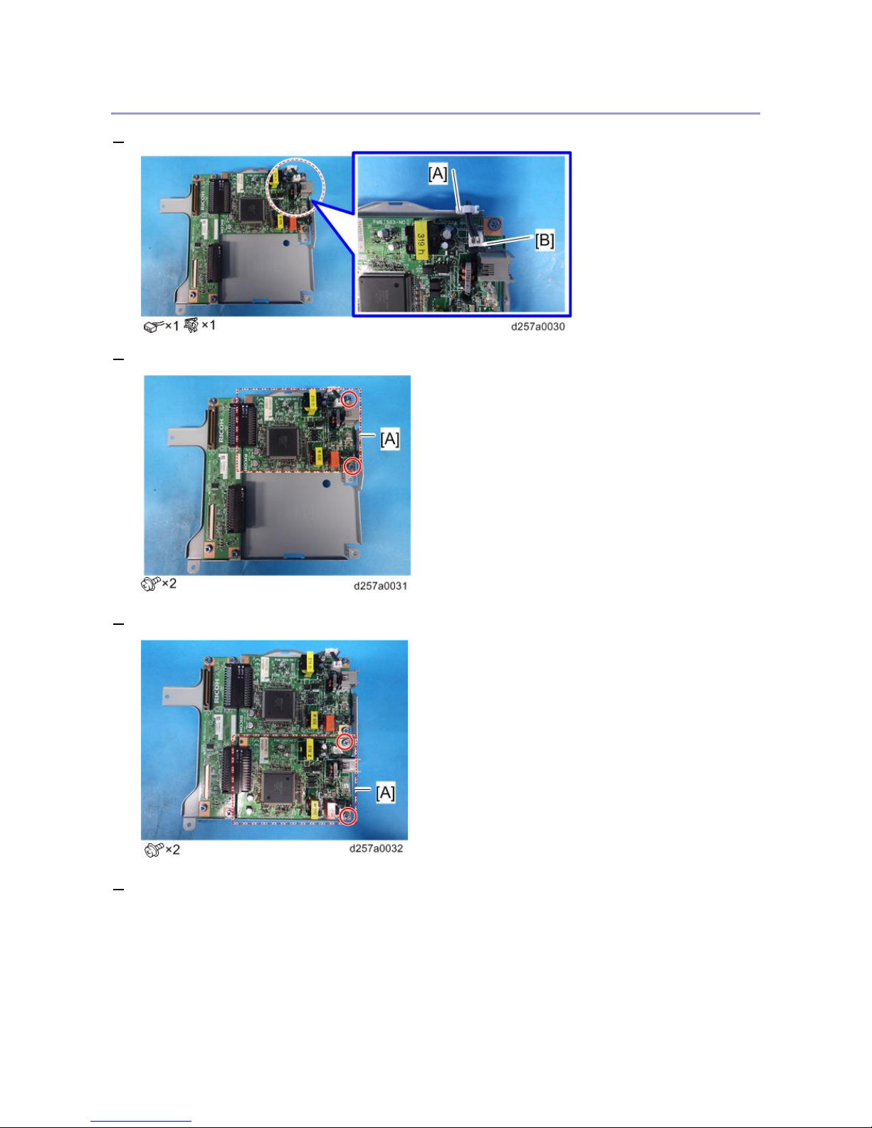
1. Switch the battery jumper switch [A] on the FCU to the "ON" position.
1.Installation
5
• If you do not switch the battery jumper switch position, the fax unit is not recognized.
2. Attach the speaker bracket [B] to the FCU [A].
3. Connect the connector [A].
1.Installation
6
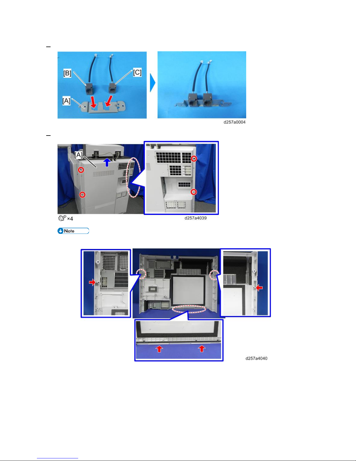
4. Attach the two modular harnesses [B] (TEL: 2 pin) and [C] (LINE1: 3 pin) to the modular bracket [A].
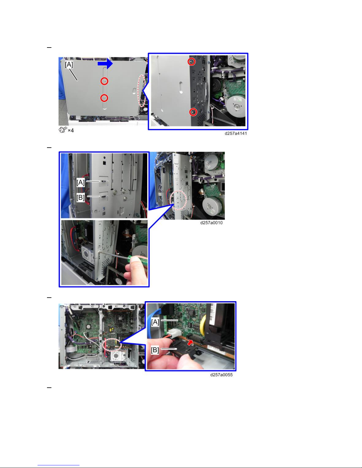
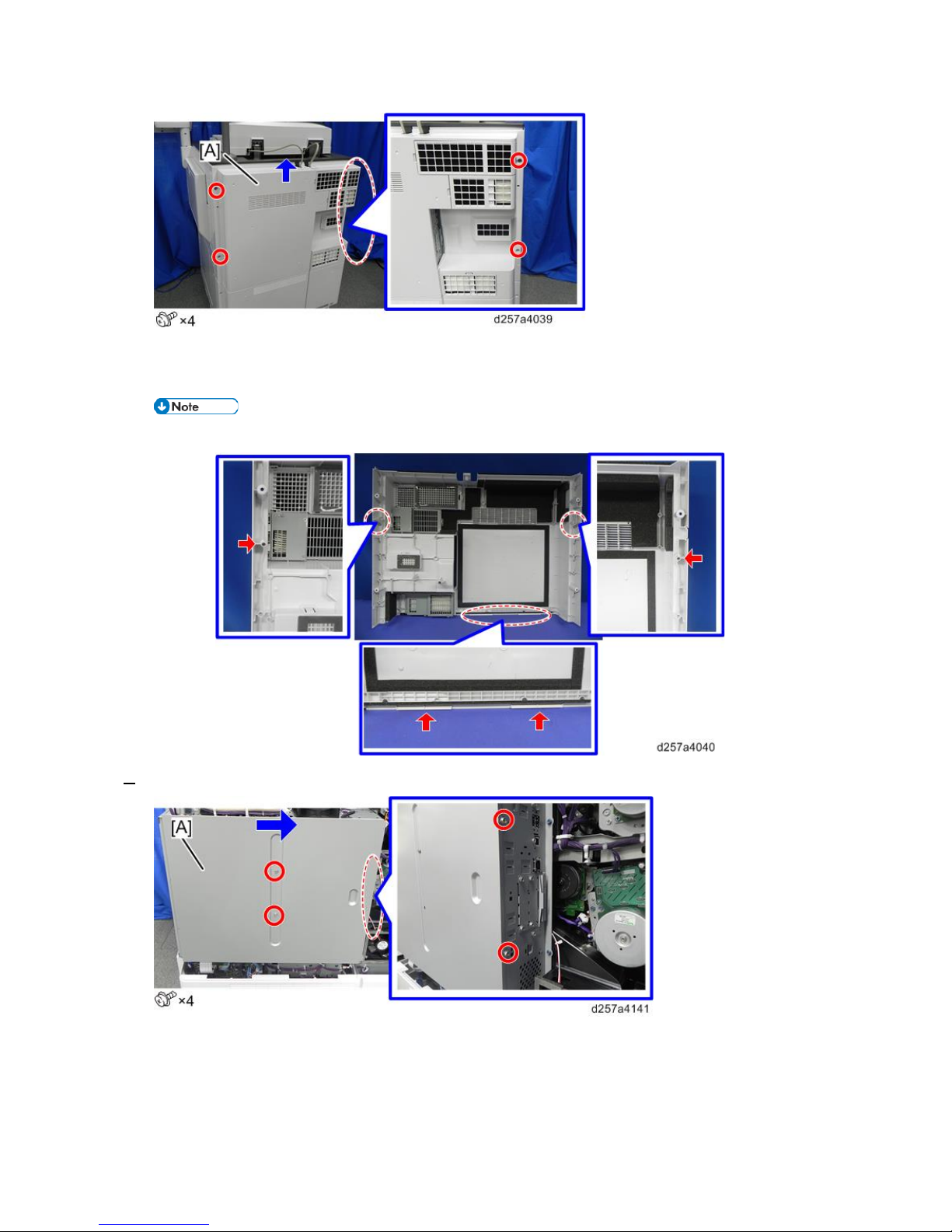
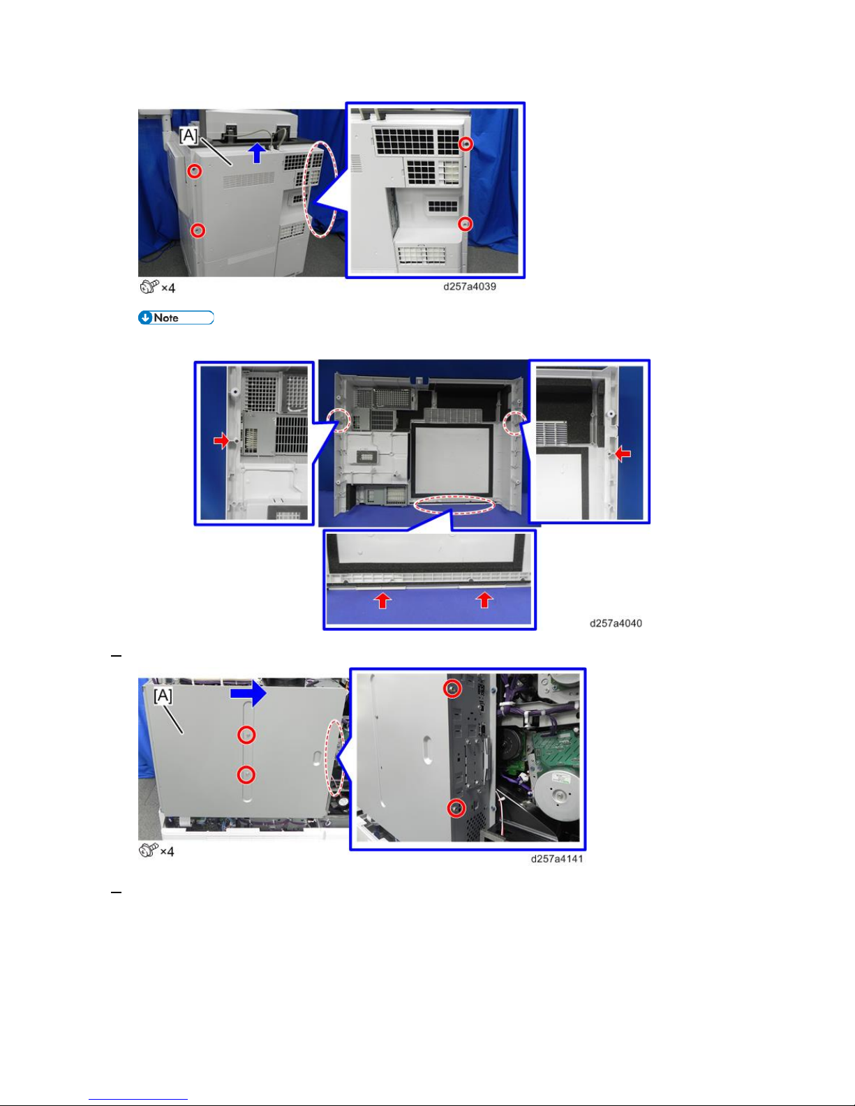
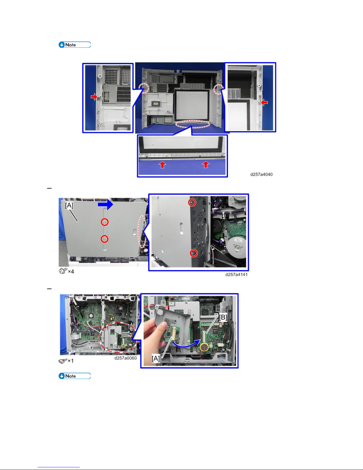
5. Remove the rear middle cover [A].
• Check the position of bosses and hooks before removing the cover.
1.Installation
7
6. Remove the controller box cover [A].
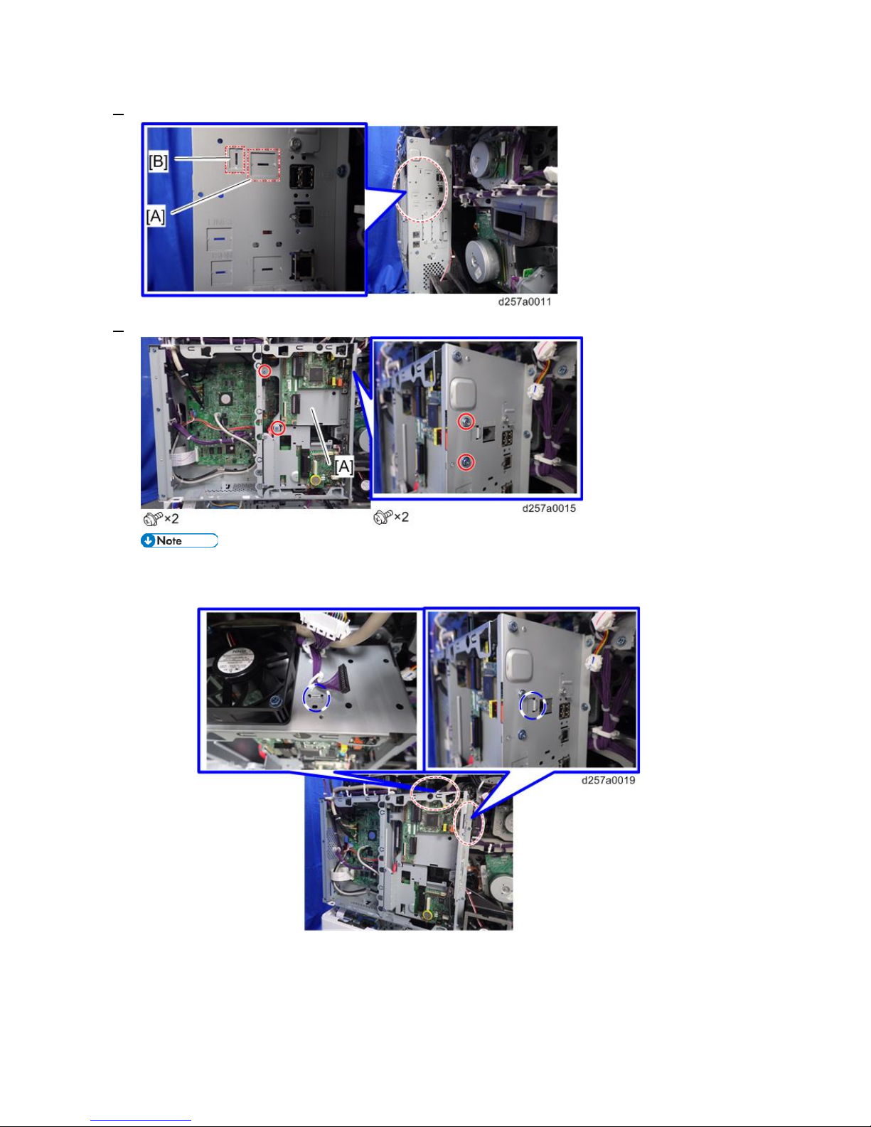
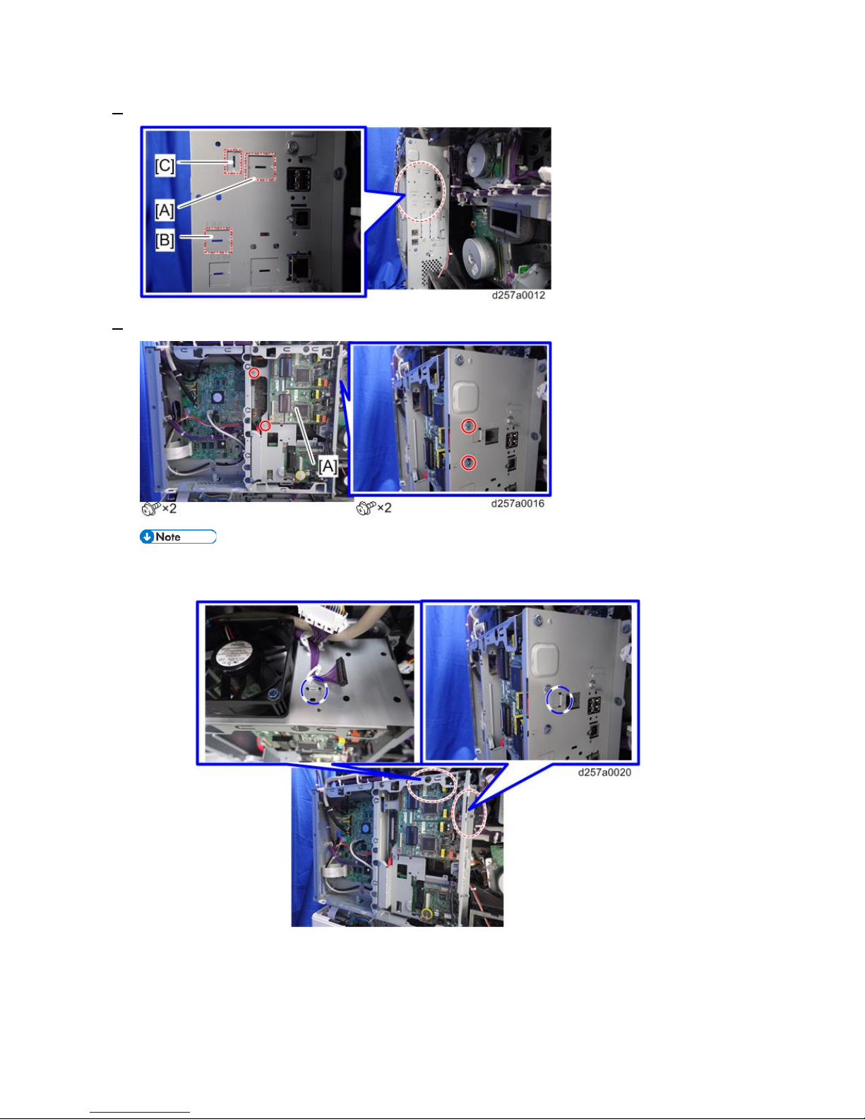
7. Cut off the port of the "LINE1" [A] and "TEL" [B] of the controller box using a screwdriver.
8. Insert the connector [B] provided with the fax unit to the controller board [A].
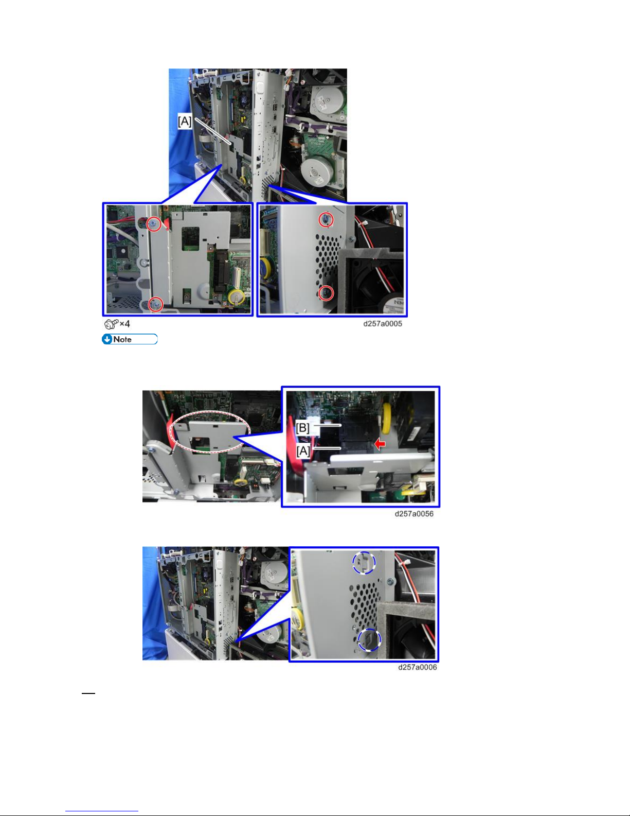
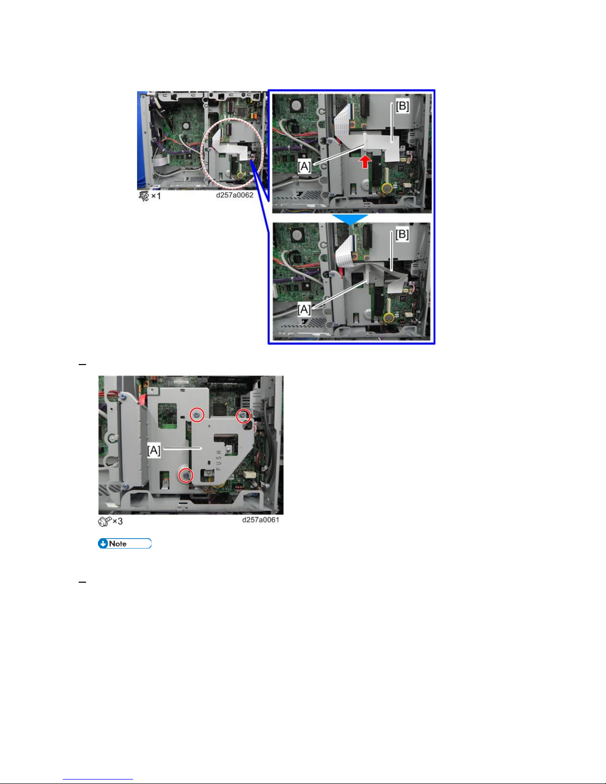
9. Install the FCU [A] on the controller board.
1.Installation
8
• When attaching the FCU, connect the co nnector [A] of the FCU to the connector [B] on the
controller box side.
• Check that the hooks of the fax unit are hooked to the controller box.
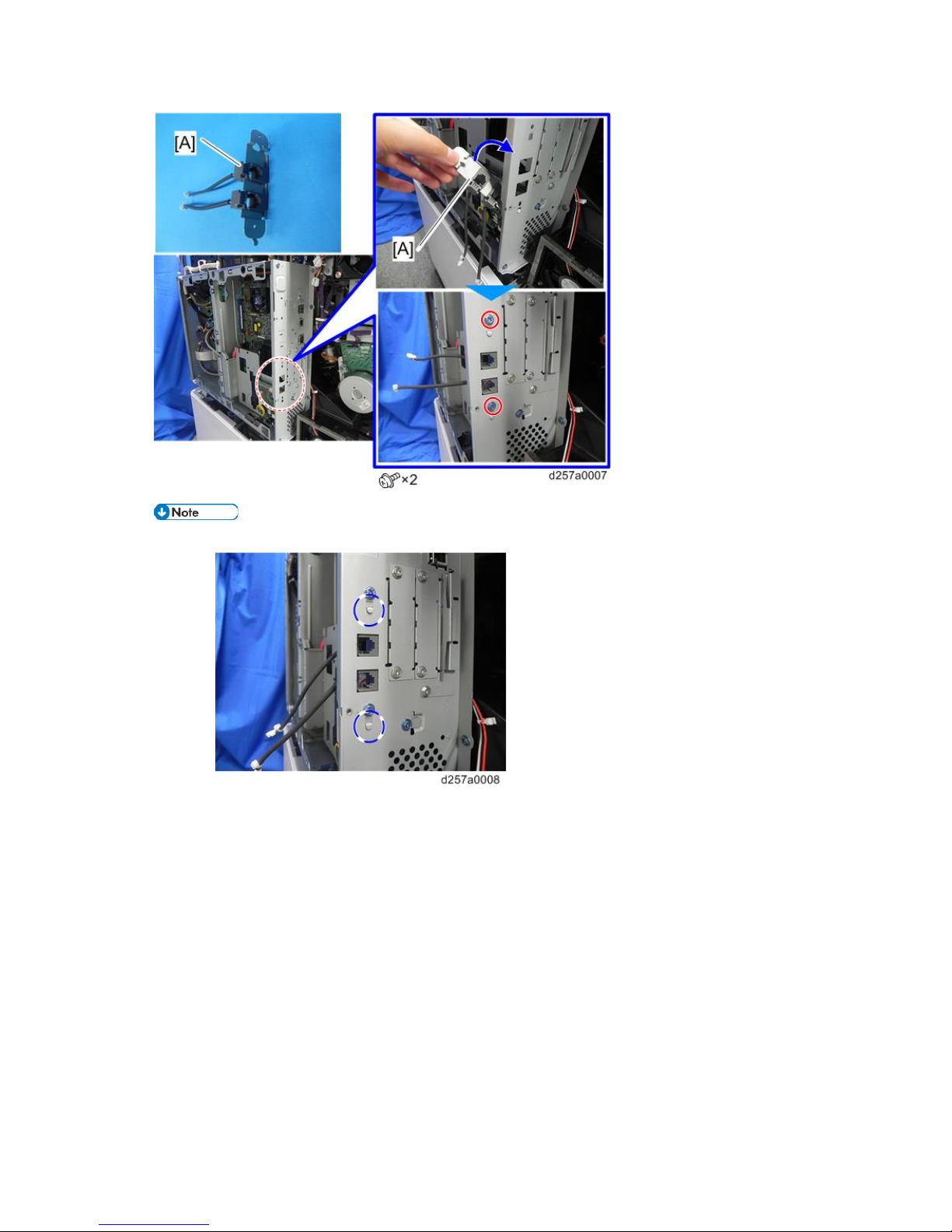
10. Attach the modular bracket [A] to the controller box.
1.Installation
9
• Insert the hooks of the modular bracket into the controller box when installing the modular bracket.
1.Installation
10
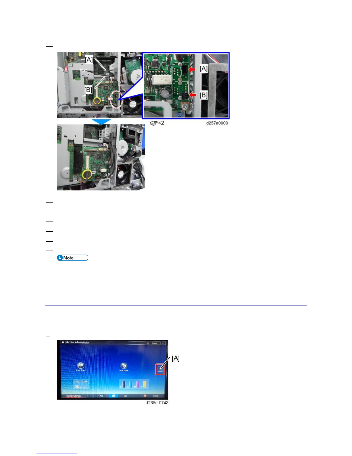
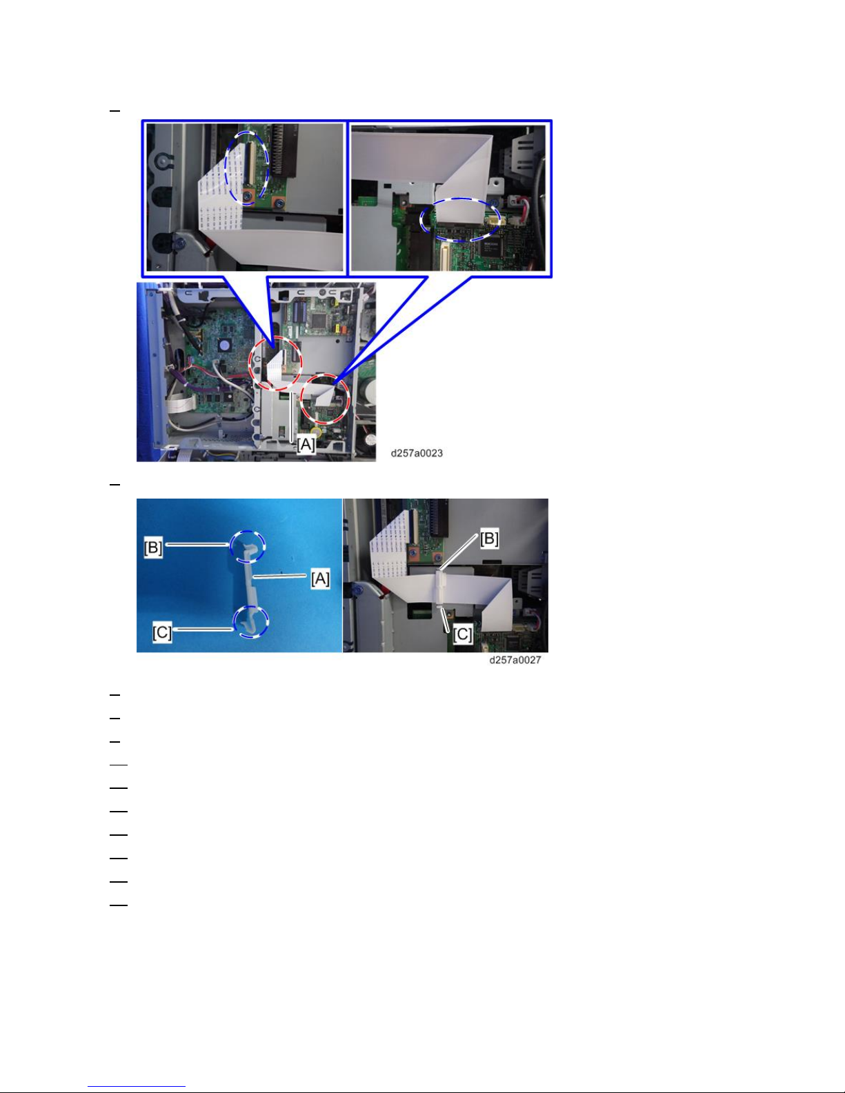
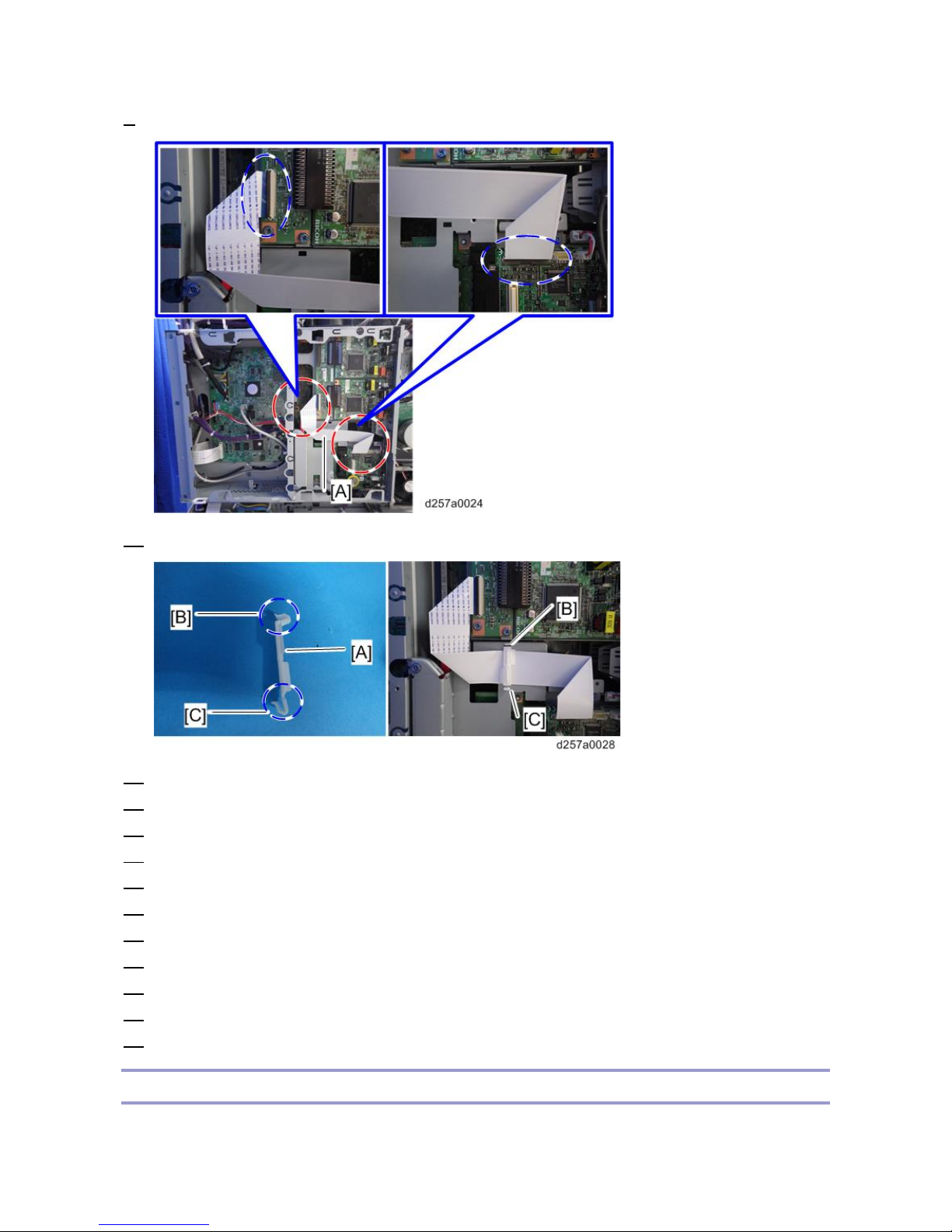
11. Connect the two modular harnesses [A] (LINE1: 3 pin) and [B] (TEL: 2 pin) to the FCU.
12. Reinstall the controller box cover and the rear middle cover.
13. Connect the telephone cord to the "LINE 1" jack.
14. Attach the serial number decal under the machine serial number decal on the rear cover of the machine.
15. Attach the FCC decal on the rear cover of the machine (NA only).
16. Keep the EMC address decal at the customer site (EU only).
17. Insert the power plug into the outlet. Turn ON the main power of the machine.
• Make sure that the outlet is grounded.
• "SRAM formatted" is displayed on the operation panel after the main power is turned ON. Turn the
main power OFF and then ON again for normal use.
Adding Fax Application Icons to the Home Screen
The fax application icon is normally added automatically. However, if it is missing from the Home screen, add it
as follows:
1. Press the [Application List] key [A].
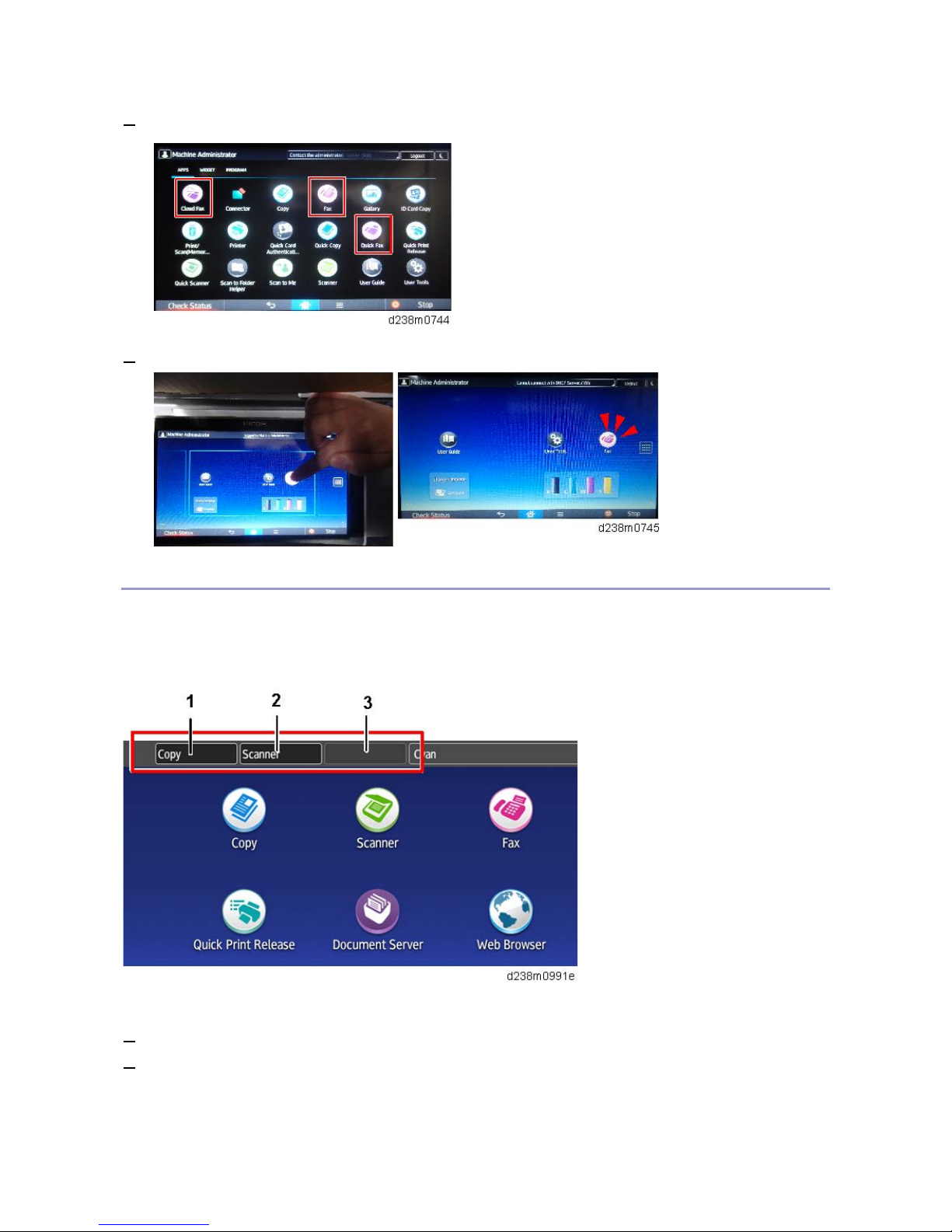
1.Installation
11
2. Press and hold the Fax application from the app list.
3. Drag and position the application on the home screen.
Registering Function Keys
By registering a fax application to a function key on the Home screen, you can open the application from any
page. Specify the setting as required.
Function Keys 1, 2, and 3 are from the left, as shown:
Allocate an application to a function key as follows:
1. Login as the machine administrator
2. Press “User Tools” icon > “Screen Features”.
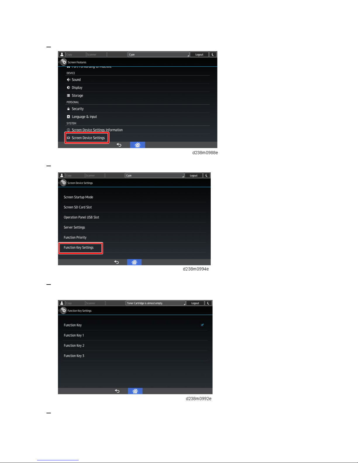
1.Installation
12
3. Press [Screen Device Settings].
4. Press [Function Key Settings].
5. Select the key to register.
To disable a function key, deselect the corresponding function key check box.
6. Press [Allocated Function], and then select the fax application.
In [Display Name], you can change the name of the icon on the Home screen (using up to 64 characters).
1.Installation
13
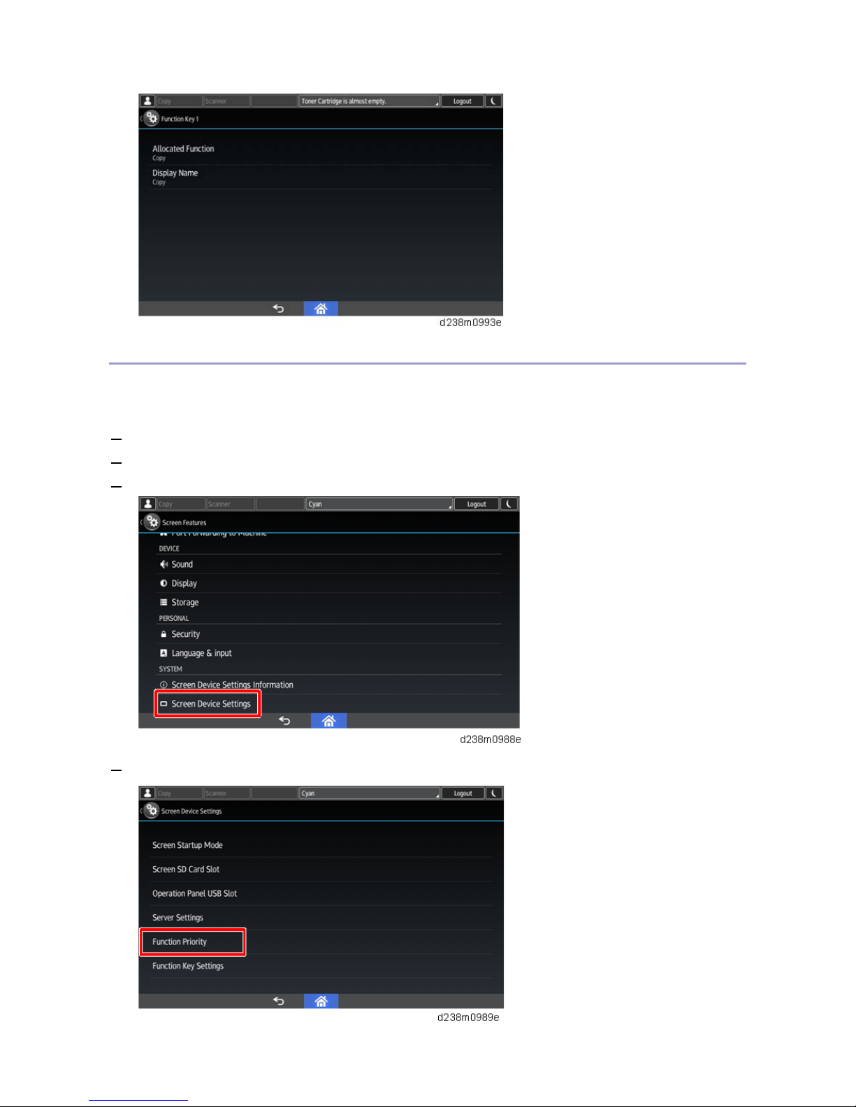
Function Priority Setting
You can specify whether the fax application appears on the operation panel just after turning the power on or just
after the system is reset automatically.
1. Login as the machine administrator
2. Press “User Tools” icon > “Screen Features”.
3. Press [Screen Device Settings].
4. Press [Function Priority].

1.Installation
14
5. Select the fax application.
Notes for Connecting the Telephone Line
Checking the following before connecting the telephone line:
If a phone line dedicated to business phones is connected to the MFP, the fax board may be damaged. Make sure
that the connecting phone line is for fax.
Reasons why the Fax Board may be damaged
Business phones have various functions. To operate those functions, a high current is supplied to a business phone
line. This may damage comp o n ents on the Fax board.
1.Installation
15
G3 Interface Unit Type M26 (D3D9-07, -08, -12)
Accessory Check
Check the quantity and condition of th e accessories against the following list.
No. Description Q'ty Remarks
1 SG3 Interface Unit 1
2 Telephone Cable 1 NA only
2 Ferrite Core 1 For NA, this ferrite core is attached to the telephone cable.
3 Screw: M3x6 4
4 HARNESS:FFC-CCU 1
5 CLAMP RFC-33V0 1
- E MC Address Decal 1 EU only
- FCC Decal 1 NA only
Installation Procedure
• Before installing this fax unit, print out all data in the printer buffer. Turn the main power to OFF and
disconnect the power cord and the network cable.
An additional two SG3 boards can be added for this model. Follow the procedures for installing a single SG3
board or double SG3 board as required.
Single G3 Board
1. Remove the rear middle cover.
1.Installation
16
• Check the position of bosses and hooks before removing the cover.
2. Remove the controller box cover [A].
1.Installation
17
3. Cut off the port of the "LINE2" [A] and the slot next to it [B] of the controller box using a screwdriver.
4. Install the G3 interface unit [A] on the controller box.
• Insert the hooks of the G3 interface unit into the controller box when installing the G3 interface
box.
1.Installation
18
5. Connect the fax unit and the G3 interface unit with the flat cable [A].
6. Attach the clamp [A], facing upward the [B] side and facing downward the [C] side.
7. Reinstall the controller box cover and the rear middle cover.
8. Attach the FCC decal on the rear cover of the machine (NA only).
9. Keep the EMC address decal at the customer site (EU only).
10. Connect the telephone cord to the "LINE2" jack.
11. Insert the power plug into the outlet. Turn ON the main power of the machine.
12. Enter the service mode. Set Bit 1 of Communication Switch 16 to "1" (SP1-104-023).
13. Exit the service mode.
14. Turn the main power OFF then ON.
15. Print out the system parameter list. Check that "G3" is displayed as an option.
16. Set up and program the items required for PSTN-2 communications.
1.Installation
19
Double G3 Boards
1. Disconnect the clamp [A] and connector [B] from the second G3 interface unit.
2. Remove the G3 board [A] from the second G3 interface unit for the two-G3 board ins tall ation.
3. Install the G3 board [A] removed from the second G3 interface unit on the first G3 interface unit.
4. Remove the rear middle cover [A].
1.Installation
20
• Check the position of bosses and hooks before removing the cover.
5. Remove the controller box cover [A].
6. Cut off the covers for the "LINE2" [A] and "LINE3" [B] ports of the controller box using a screwdriver.
1.Installation
21
7. Cut off the cover of the port [C] using a screwdriver.
8. Install the G3 interface unit [A] on the controller board.
• Insert the hooks of the G3 interface unit into the controller box when installing the G3 interface
box.
1.Installation
22
9. Connect the fax unit and the G3 interface unit with the flat cable [A].
10. Attach the clamp [A], with the [B] side facing upward and the [C] side facing downward.
11. Reinstall the controller box cover and the rear middle cover.
12. Attach the FCC decal on the rear cover of the machine (NA only).
13. Keep the EMC address decal at the customer site (EU only).
14. Connect the telephone cords to the "LINE2" and "LINE3" jacks for double-G3 board installation.
15. Insert the power plug into the outlet. Turn ON the main power of the machine.
16. Enter the service mode. Set Bit 1 of Communication Switch 16 to "1" (SP1-104-023).
17. Set Bit 3 of Communication Switch 16 to "1" (SP1-104-023).
18. Exit the service mode.
19. Turn the main power ON then OFF.
20. Print out the system parameter list. Check that "G3" is displayed as an option.
21. Set up and program the items required for PSTN-2 communications.
Notes for Connecting the Telephone Line
Checking the following before connecting the telephone line:

1.Installation
23
If a phone line dedicated to business phones is connected to the MFP, the fax board may be damaged. Make sure
that the connecting phone line is for fax.
Reasons why the Fax Board may be damaged
Business phones have various functions. To operate those functions, a high current is supplied to a business phone
line. This may damage comp o n ents on the Fax board.
1.Installation
24
Fax Unit Options
Fax Memory Unit Type M26 64MB (D3D9)
Accessory Check
Check the quantity and condition of th e accessories against the following list.
No. Description Q'ty
1 Bracket 1
2 Memory unit 1
3 Screws M3x5 2
4 Screws M3x6 3
Installation Procedure
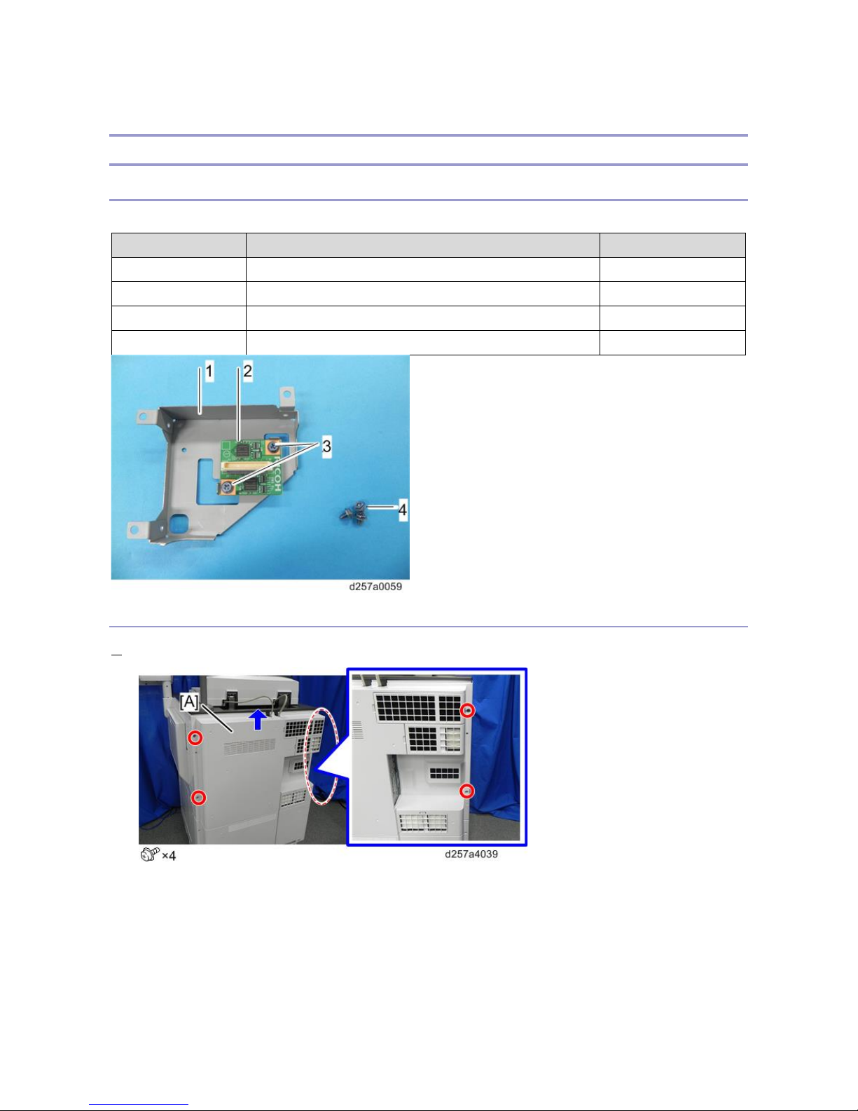
1. Remove the rear middle cover.
1.Installation
25
• Check the position of bosses and hooks before removing the cover.
2. Remove the controller box cover [A].
3. Connect the memory unit connector [A] to the FCU [B].
If the G3 interface unit has been installed, do the following before Step 3.
1.Installation
26
• Open the lower part of the clamp [A] and slide the FFC until you see the screw hole.
4. Secure the bracket [A].
Put the FFC and clamp back into place if you moved them before step 3.
5. Re-assemble the machine.
 Loading...