

Page 1
D158/D159/D160/D161/D170
DETAILED DESCRIPTIONS
MANUAL
Page 2

D158/D159/D160/D161/D170
DETAILED DE SCRIPTIONS
TABLE OF CONTENTS
1. OVERVIEW .................................................................................... 1
1.1 COMPONENT LAYOUT ................................................................................... 1
1.1.1 D160/D161/D170: CIS SCANNER COMPONENT LAYOUT ................ 3
1.1.2 D158/D159: CCD SCANNER COMPONENT LAYOUT ........................ 3
1.2 PAPER PATH ................................................................................................... 4
1.3 DRIVE LAYOUT................................................................................................ 5
2. BOARD STRUCTURE .................................................................... 7
2.1 BLOCK DIAGRAM ............................................................................................ 7
BICU (Base Engine and Image Control Unit) ............................................ 8
2.2 SBU (SENSOR BOARD UNIT) ........................................................................ 8
3. COPY PROCESS OVERVIEW ....................................................... 9
4. SCANNING D158/D15 9 ................................................................ 11
4.1 OVERVIEW ..................................................................................................... 11
4.2 SCANNER DRIVE .......................................................................................... 12
4.3 ORIGINAL SIZE DETECTION IN PLATEN MODE ....................................... 13
4.4 ANTI-CONDENSATION HEATER ................................................................. 14
5. SCANNING D160/D16 1/D170 ...................................................... 15
5.1 OVERVIEW ..................................................................................................... 15
5.2 SCANNER DRIVE .......................................................................................... 16
6. LASER EXPOSURE ..................................................................... 18
6.1 OVERVIEW ..................................................................................................... 18
6.2 AUTO POWER CONTROL (APC) ................................................................. 19
6.3 LD SAFETY SWITCH ..................................................................................... 20
7. PHOTOCONDUCTOR UNIT (PCU) .............................................. 21
7.1 OVERVIEW ..................................................................................................... 21
7.2 DRIVE ............................................................................................................. 23
8. DRUM CHARGE .......................................................................... 24
8.1 OVERVIEW ..................................................................................................... 24
8.2 ID SENSOR PATTERN PRODUCTION TIMING .......................................... 25
8.3 DRUM CHARGE ROLLER CLEANING ......................................................... 26
9. DEVELOPMENT .......................................................................... 27
9.1 OVERVIEW ..................................................................................................... 27
9.2 DRIVE ............................................................................................................. 28
Detailed Descriptions i D158/D159/D160/D161/D170
Page 3

9.3
DEVELOPER MIXING .................................................................................... 29
9.4 DEVELOPMENT BIAS ................................................................................... 30
9.5 TONER SUPPLY ............................................................................................ 31
9.5.1 TONER BOTTLE REPLENISHMENT MECHANISM ........................... 31
9.6 TONER SUPPLY MECHANISM .................................................................... 32
9.7 TONER DENSITY CONTROL ....................................................................... 33
9.7.1 OVERVIEW ........................................................................................... 33
9.7.2 TONER DENSITY SENSOR INITIAL SETTING .................................. 35
9.7.3 TONER CONCENTRATION MEASUREMENT ................................... 35
9.7.4 VSP/VSG DETECTION......................................................................... 35
9.7.5 TONER SUPPLY REFERENCE VOLTAGE (VREF) DETERMINATION
36
9.7.6 TONER SUPPLY DETERMINATION ................................................... 36
9.7.7 TONER SUPPLY MOTOR ON TIME DETERMINATIONS ................. 36
9.8 TONER SUPPLY IN ABNORMAL SENSOR CONDITIONS......................... 38
9.8.1 ID SENSOR ........................................................................................... 38
9.8.2 TD SENSOR .......................................................................................... 38
9.9 TONER NEAR END/END DETECTION AND RECOVERY.......................... 38
9.9.1 TONER NEAR END DETECTION ........................................................ 38
9.9.2 TONER NEAR END RECOVERY ........................................................ 39
9.9.3 TONER END DETECTION ................................................................... 39
9.9.4 TONER END RECOVERY.................................................................... 39
10. DRUM CLEANING AND TONER RECYCLING............................ 40
10.1 DRUM CLEANING.................................................................................... 40
10.2 TONER RECYCLING ............................................................................... 41
11. PAPER FEED ............................................................................... 42
11.1 OVERVIEW ............................................................................................... 42
11.2 PAPER FEED DRIVE MECHANISM ....................................................... 43
11.3 PAPER FEED AND SEPARATION MECHANISM .................................. 44
11.4 PAPER LIFT MECHANIS M ...................................................................... 45
11.5 BY-PASS TRAY BOTTOM PLATE LIFT MECHANISM .......................... 46
11.6 PAPER END DETECTION ....................................................................... 47
11.7 PAPER SIZE DETECTION ...................................................................... 48
11.7.1 PAPER TRAY ................................................................................. 48
0: PUSHED, 1: NOT PUSHED .......................................................... 48
11.7.2 BY-PASS TRAY ............................................................................. 50
11.8 SIDE FENCES .......................................................................................... 51
11.9 PAPER REGISTRATION ......................................................................... 52
12. IMAGE TRANSFER AND PAPER SEPARATION ........................ 53
12.1 OVERVIEW ............................................................................................... 53
12.2 IMAGE TRANSFER CURRENT TIMING ................................................. 54
12.3 TRANSFER ROLLER CLEANING ........................................................... 55
12.4 PAPER SEPARATION MECHANISM...................................................... 56
13. IMAGE FUSING AND PAPER EXIT ............................................. 57
13.1 OVERVIEW ............................................................................................... 57
D158/D159/D160/D161/D170 ii Detailed Descriptions
Page 4

13.2 FUSING UNIT DRIVE AND RELEASE MECHANISM ............................ 58
13.2.1 FUSING UNIT DRIVE .................................................................... 58
13.2.2 DRIVE RELEASE MECHANISM ................................................... 58
13.2.3 CONTACT/RELEASE CONTROL ................................................. 59
13.2.4 DRIVE RELEASE SOLENOID ....................................................... 59
13.3 FUSING ENTRANCE GUIDE SHIFT ....................................................... 60
13.4 PRESSURE ROLLER .............................................................................. 60
13.5 FUSING TEMPERATURE CONTROL..................................................... 61
13.5.1 OVERVIEW .................................................................................... 61
13.5.2 TEMPERATURE CONTROL ......................................................... 62
13.6 OVERHEAT PROTECTION ..................................................................... 64
14. DUPLEX UNIT .............................................................................. 65
14.1 OVERALL.................................................................................................. 65
14.2 DRIVE MECHANISM ................................................................................ 66
14.3 BASIC OPERATION ................................................................................. 67
14.4 FEED IN AND EXIT MECHANISM .......................................................... 69
15. ENERGY SAVER MODES OF BASIC MACHINES ...................... 70
15.1 OVERVIEW ............................................................................................... 70
15.2 AOF ........................................................................................................... 71
15.3 TIMERS ..................................................................................................... 71
15.4 RECOVERY .............................................................................................. 71
16. ENERGY SAVER MODES OF GDI MACHINES .......................... 72
16.1 OVERVIEW ............................................................................................... 72
16.2 AOF ........................................................................................................... 73
16.3 TIMERS ..................................................................................................... 73
16.4 RECOVERY .............................................................................................. 73
17. OVERVIEW .................................................................................. 74
18. BOARDS ...................................................................................... 75
18.1 FCU ........................................................................................................... 75
19. SERVICE RAM ADDRESSES ...................................................... 77
20. VIDEO DATA PATH ..................................................................... 91
20.1 TRANSMISSION ...................................................................................... 91
20.1.1 MEMORY TRANSMISSION AND PARALLEL MEMORY
TRANSMISSION ............................................................................................ 91
20.1.2 IMMEDIATE TRANSMISSION ...................................................... 92
20.1.3 JBIG TRANSMISSION ................................................................... 92
20.1.4 ADJUSTMENTS ............................................................................. 92
20.2 RECEPTION ............................................................................................. 93
21. FAX COMMUNICATION FEATURES .......................................... 94
21.1 DOCUMENT SERVER ............................................................................. 94
21.2 INTERNET MAIL COMMUNICATION ..................................................... 95
21.2.1 MAIL TRANSMISSION .................................................................. 95
Detailed Descriptions iii D158/D159/D160/D161/D170
Page 5

21.2.2
MAIL RECEPTION ......................................................................... 98
21.2.3 HANDLING MAIL RECEPTION ERRORS .................................. 100
21.2.4 SECURE INTERNET RECEPTION ............................................. 101
21.2.5 TRANSFER REQUEST: REQUEST BY MAIL ............................ 101
21.2.6 E-MAIL OPTIONS (SUB TX MODE) ........................................... 102
22. IP-FAX ........................................................................................ 106
22.1 WHAT IS IP-FAX? .................................................................................. 106
22.2 T.38 PACKET FORMAT ......................................................................... 106
22.2.1 UDP RELATED SWITCHES ........................................................ 106
22.3 SETTINGS .............................................................................................. 106
D158/D159/D160/D161/D170 iv Detailed Descriptions
Page 6
1. OVERVIEW
The ab ove il lu s tr ation is th e D158/D159 model.
1.1 COMPONENT LAYOUT
Component Layout
• D170: No duplex unit
• D158/D159: CCD scanner
• D160/D161/D170: C IS scan ner
Detailed Descriptions 1 D158/D159/D160/D161/D170
Page 7

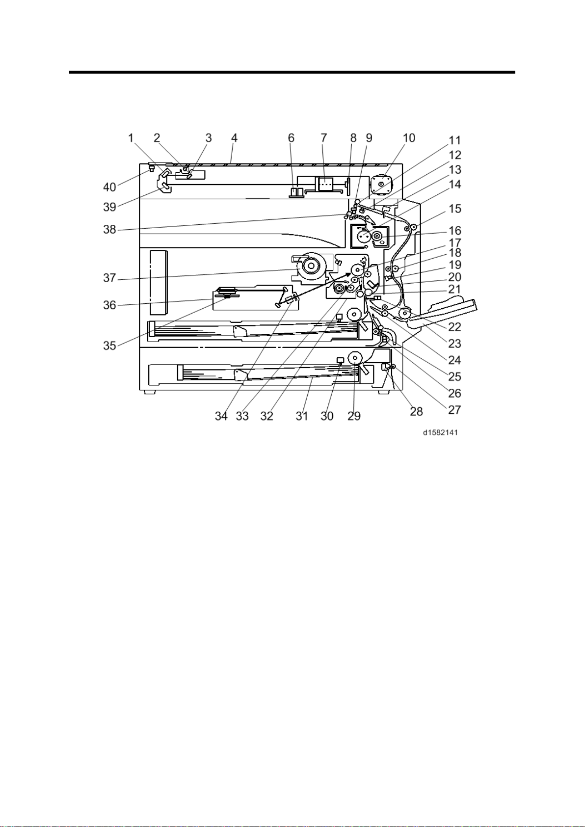
Component Layout
1. 2nd Mirror
2. Exposure Lamp
3. 1st Mirror
4. Exposure Glass
6.
7. Lens Block
8. SBU
9. Exit Sensor
10. Scanner Motor
11. Inverter Roller
12. Duplex Invert er Sensor
13. Duple
14 . H ot R oll er
15. Upper Transport Roller
16. Pressure Roller
17. OPC Drum
18 . Middl e Transpor t R oller
19. Duplex Exit Sensor
20. Image Density S ensor
21 . R egist rat ion Roll er
22 . R egist rat ion Sen sor
23. By
24 . L ower Trans port Ro
25. Upper Relay Roller
26 . R elay Sen sor
27 . L ower Relay Roller
28. Vertical Transport Sensor
29 . Paper Feed Roller
30. Paper End Sensor
31. Bottom Pla te
32. PCU
33 . D evelopment Rol ler
34. WTL
35. Polygon Mirror Motor
36. Laser Unit
37. Toner Supply Bo
38. Ex it Ro ller
39. 3rd Mirror
40. Scanner HP Sensor
APS sensor (Length)
D158/D159/D160/D161/D170 2 Detailed Descriptions
x Entrance Sensor
-pass Tray
ller
tt le H older
Page 8
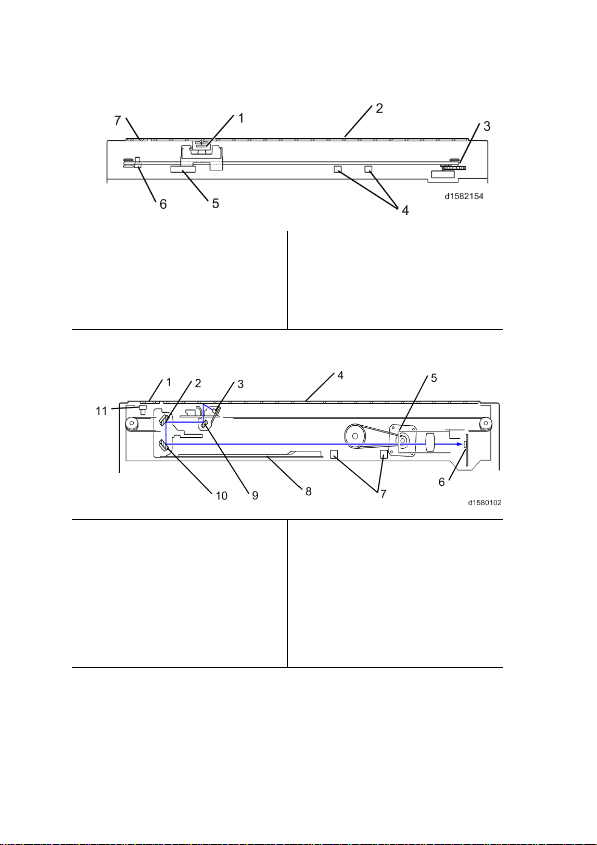
Component Layout
1.CIS Unit
2
3
4
5
6
7. DF
1. DF Exposure Glass
2.
3
4
5
6. SBU
7
8
9
10.3
11. Scanner HP Sensor
1.1.1 D160/D161/D170: CIS SCANNER COMPONENT LAYOUT
. APS Sensor (Width)
. Exposure Glass
. S canner HP Sen sor
. Scanner Motor
Exposure Glass
. APS Sensor (Length)
1.1.2 D158/D159: CCD SCANNER COMPONENT LAYOUT
2n d M irror
. Exposure Lamp
. Exposure Glass
. Scanner Motor
. APS Sensors
. Scanner Heater
. 1st Mirror
rd
Mirror
Detailed Descriptions 3 D158/D159/D160/D161/D170
Page 9
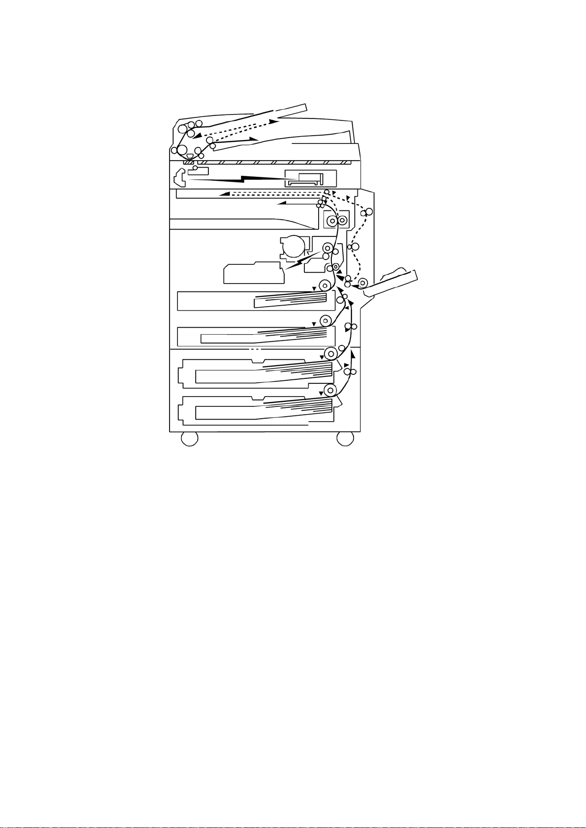
Paper Path
1.2 PAPER PATH
The D158, D159, D160, and D161 models have a duplex unit mounted on the right side of
the machine.
All models have a b y-p ass tr ay.
D158/D159/D160/D161/D170 4 Detailed Descriptions
Page 10
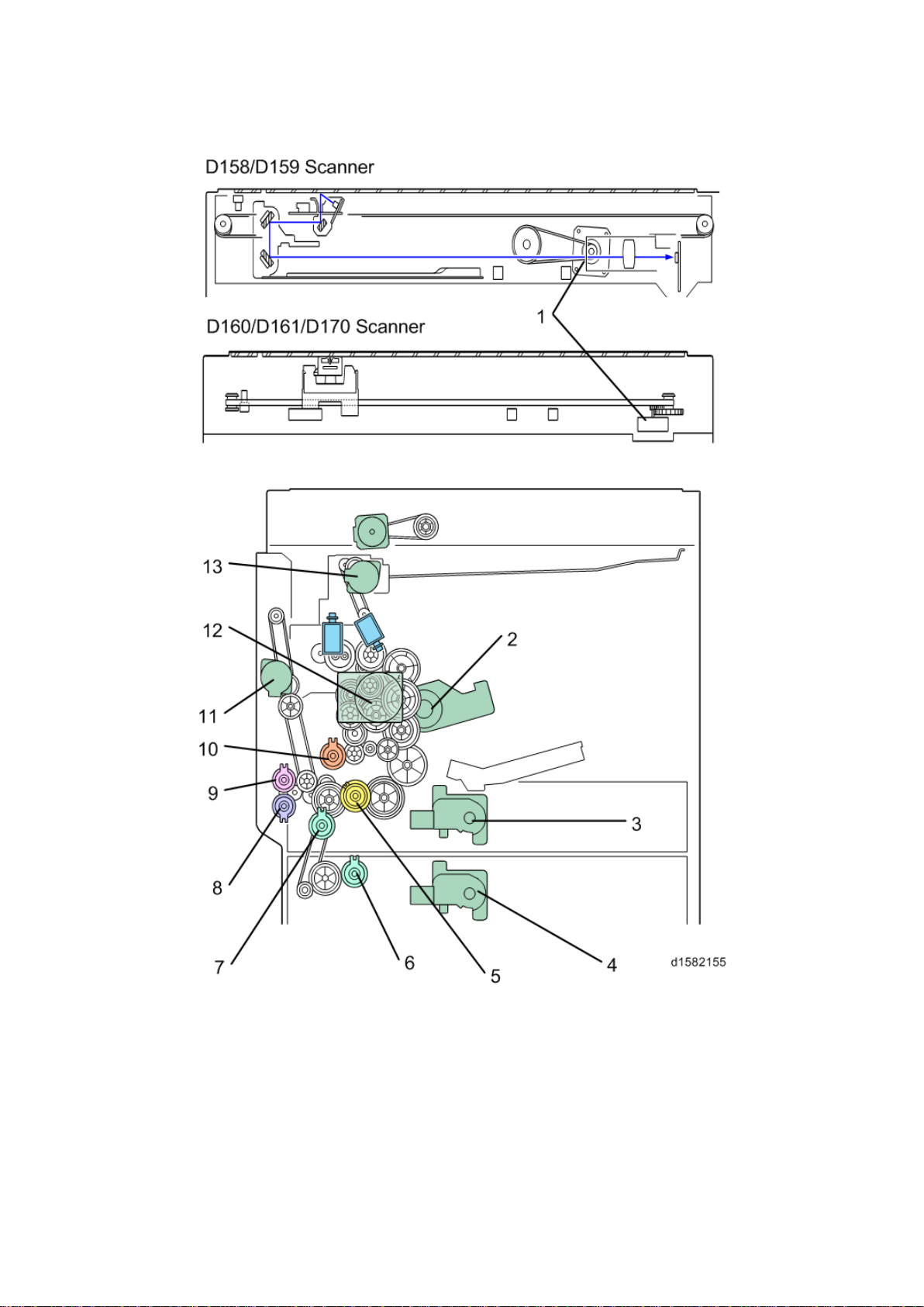
1.3 DRIVE LAYOUT
Dri ve L ayou t
Detailed Descriptions 5 D158/D159/D160/D161/D170
Page 11

Dri ve L ayou t
1. Scanner Motor
8. By-pas s P aper Feed C lu tch
2. Toner Su pply M otor
3. Tray 1 Lift M otor
4. Tray 2Lift Motor
5. Upper Paper Feed Clutch
6. L ower Paper Feed Clutch
7. R elay Clut ch
9. By-pass Tray Lift Clutc h
10. Registration Clutch
11. Duplex Motor
12 . Main M otor
13. Inver ter Motor
D158/D159/D160/D161/D170 6 Detailed Descriptions
Page 12
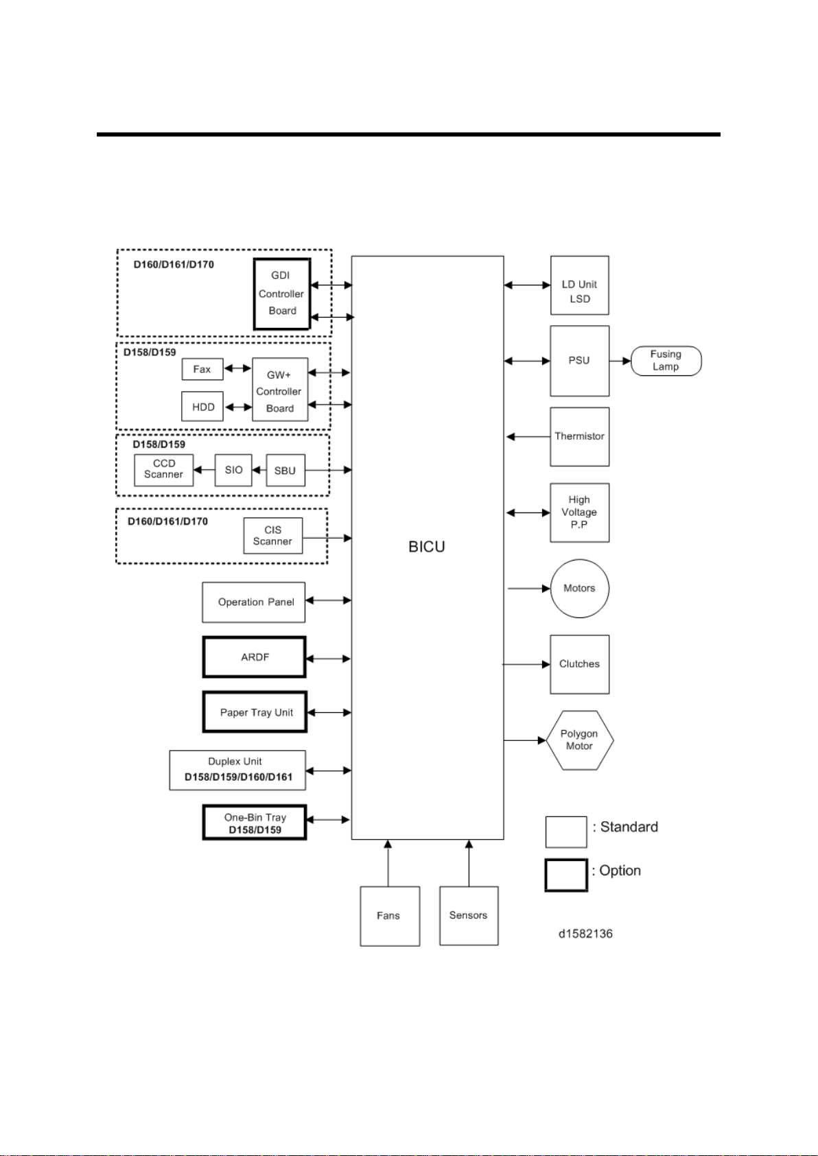
2. BOARD STRUCTURE
2.1 BLOCK DIAGRAM
Block Diagram
Detailed Descriptions 7 D158/D159/D160/D161/D170
Page 13

SBU (Sensor Board Unit)
BICU (Base Engine and Image Control Unit)
The main board con tr ols the following functions:
Engine sequence
Timing control for peripherals
Im age processing, v ideo control
Operati on c ont rol, syst em contr ol ( Basic m achine only)
Mach in e con trol
Dri ve c ont rol for the sens ors, m otor s, and clutches of t he print er and scanner
High voltage supply board control
Serial in terfac es with p eripherals
Fusing control
2.2 SBU (SENSOR BOARD UNIT)
The SBU d eals wit h the an alog signals from the CCD and con verts th em int o digi tal signals.
The SBU is attached to the CCD scanner (D158/D159).
D158/D159/D160/D161/D170 8 Detailed Descriptions
Page 14
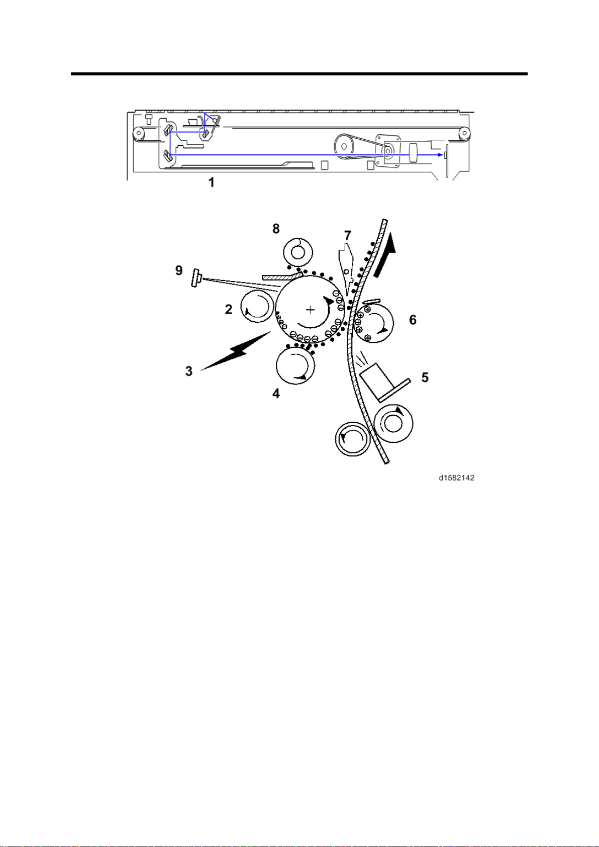
3. COPY PROCESS OVERVIEW
SBU (Sensor Board Unit)
1. Exposure
A xenon lamp exposes the origin al. Light reflec ted from the original passe s to th e CCD,
w here it is conver ted into an analog data signal. Thi s data i s c onver ted to a di gital signal,
processed and st ored in the memory. At the time of print in g, the dat a is ret rieved and
sent to the las er diode.
2. Drum Charge
In th e dark , the charge r oller gi ves a negati ve c harge to the organ ic phot o-conductive
(O PC ) drum. The c harge r emains on th e surface of the dru m because t he OP C layer has
a high elect rical resistance in th e dark .
3. Laser Exposure
The pr ocessed data scanned f rom th e origi nal is ret rieved from the memory and
trans ferred to the dru m b y a laser beam, which f orms an electrical latent image on th e
dr um surface. Th e amount of charge remainin g as a laten t image on th e drum depends
on the laser beam intensity, which is controlled by the BICU board.
Detailed Descriptions 9 D158/D159/D160/D161/D170
Page 15

SBU (Sensor Board Unit)
4. Development
The magnet ic dev elop er brus h on th e development r oll er comes in c ontac t w ith the latent
image on th e drum sur fac e. Toner par tic les are el ectrostaticall y attached t o t he areas of
the drum surface wh ere th e laser red uced the negative charge on t he drum.
5. ID Sensor
The laser for ms a sensor pat ter n on t he drum surface. The ID sens or measures th e
reflectivity of the pattern. The output signal is one o f the factors used for toner sup pl y
cont rol . Al so, the ID sensor measures t he reflectivity of t he dr um surface. The outpu t
si gnal i s us ed f or char ge roll er v oltage con tr ol.
6. Image Transfer
Paper is fed to the area between the drum surface and the tran sfer roller at the proper
ti me for ali gning t he copy paper and the developed image on th e drum surface. T hen, the
trans fer r oller applies a high positive charge t o th e rever se s ide of t he paper. T his
positi ve charge pull s the ton er partic les f rom the drum surf ace ont o the p aper. At th e
same time, the paper is electr ostatically attracted to the tr ansfer rolle r.
7. Paper Separation
Paper separates f rom the drum as a r esult of t he elect ros tati c attraction between the
paper and t he t ransf er r oller. Th e disc harge pl ate ( groun ded) helps s eparate the pap er
from the drum.
8. Cleaning
The c leanin g blade removes any toner remai ni ng on t he drum su rface after t he imag e
trans fers to the paper.
9. Quenching
The light from the quenc hing l amp electrically neutr ali zes the c harge on the drum
surface.
D158/D159/D160/D161/D170 10 Detailed Descriptions
Page 16
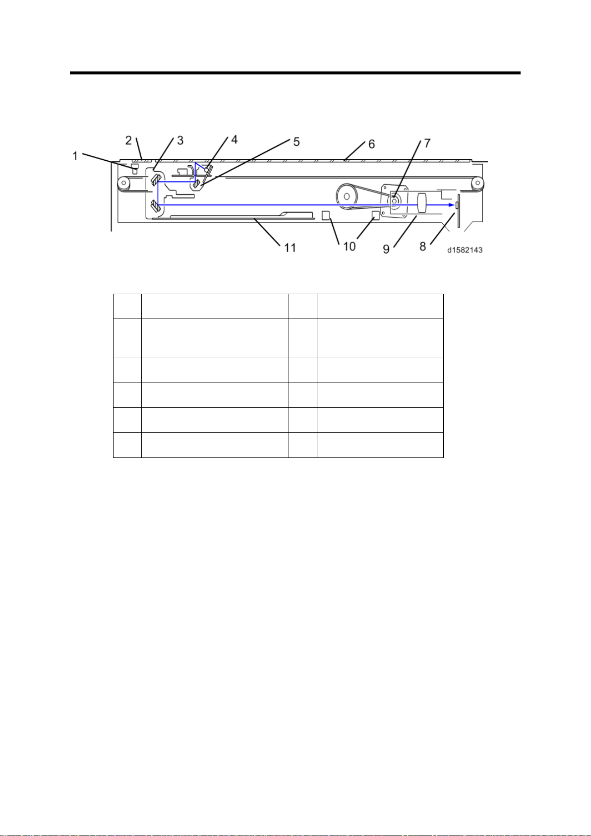
4. SCANNING D158/D159
1.
Scan ner HP s ensor
7.
Scan ner motor
2.
DF exposu re glass
8.
Sensor board unit
3.
2nd scanner (2nd carriage)
9.
Len s Block
4.
Scan ner lamp
10.
AP S s ensor
5.
1st s can ner (1s t carri age)
11.
Scanner Heater
6.
Exposure glass
4.1 OVERVIEW
Overview
(SBU)
The original on t he exp osure g la ss or ARDF exposure glass reflects the li ght emitted f rom
the scanner l amp. The reflected li ght goes t o th e CCD on the sensor b oard by way of the 1 st
and 2nd scanners. The sensor board converts th e CCD an alog sig nals into digital signals.
W hen the original is manually placed on the exposure glass, the scanner motor pulls the 1st
and 2nd scanners via mechanical linkage. The original is scanned from l eft to right.
Wh en th e origi nal is fed f rom th e optional A RDF, it is automat ical ly tr ansp orted ont o the
ARDF exposure glass, and to the original exit. The original does not stay on the glass; but
goes to the exit. T he 1st and 2nd scanners stay at their home positi ons.
Detailed Descriptions 11 D158/D159/D160/D161/D170
Page 17
Scanner Drive
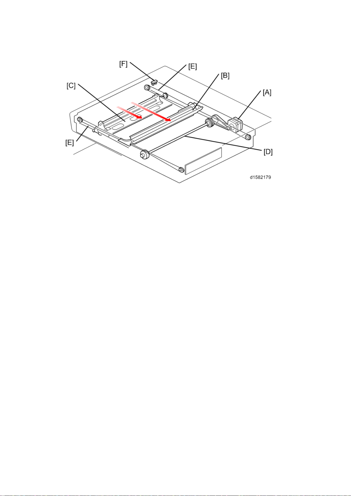
4.2 SCANNER DRIVE
The scanner mot or [A] drives the 1st scanner [B] and the 2nd scanner [C] through the
scanner drive pull ey, scan ner drive shaft [D], and t wo s canner wires [ E].
Book mode -
The SBU board controls the scanner drive motor. The 2nd scanner speed is half that of the
1st scanner.
In reduction or enlargement mode, the scan ni ng s peed depends on th e magnificat ion rat io.
The returning speed is always the same, whether in full size or magnification mode. The
image length change in the sub scan direction is done by changing the scanner m otor
speed. In the main scan direction it is done by im age processing on the BICU board.
You can adjust the magnification in the sub-scan direction by changing the scanner motor
speed with SP4-008.
ARDF mode -
The scanners always st ay in t heir home positi on (th e s canner HP sensor [F] detects the 1st
scanner ) t o sc an t he original. The AR DF motor f eeds th e ori gi nal t hrough t he A RDF. I n
reduction/enlargement mode, the image length change in the sub-scan direction is done by
changing the ARDF motor speed. Magnification in the main scan direction is done in the
BICU board. This is the same as for book mode.
You can adjust magnific ation in the sub-scan direction by changing the ARDF motor speed
with SP6 -017.
D158/D159/D160/D161/D170 12 Detailed Descriptions
Page 18
Origi n al S iz e Detection in Pl at en M ode
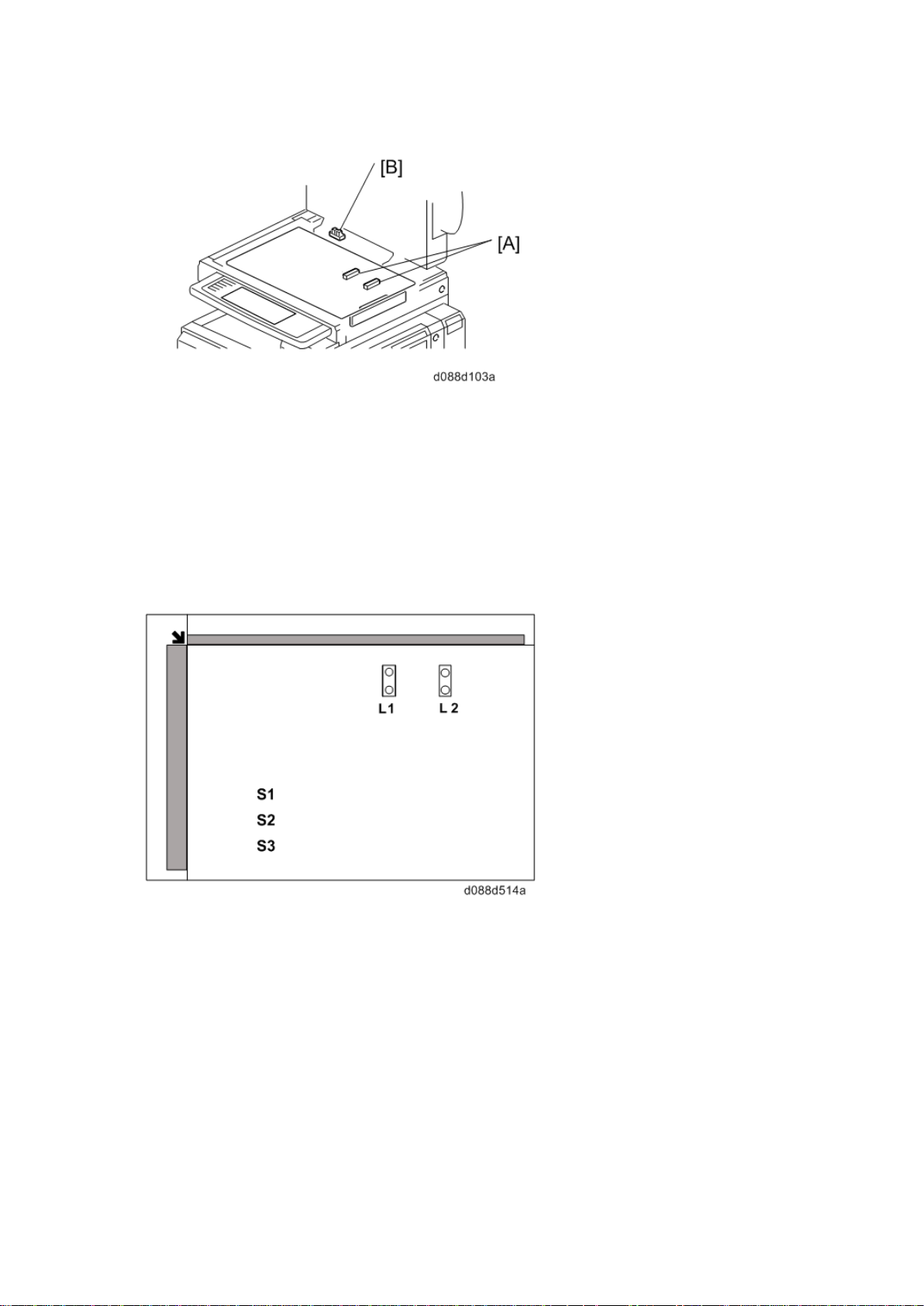
4.3 ORIGINAL SIZE DETECTION IN PLATEN MODE
Ther e are no APS s ensor ( width) in the scanner unit. However, the original width can be
detec ted by CCD . The A PS s ensor ( length) [A] det ects the original length.
The BIC U board ch eck s each s ensor status when the plat en c over s ensor [B] is
activated as it is closed. It det ects the or ig inal size by t he on/off s ignals it gets f rom each
sensor.
If the copy is mad e with t he platen cover f ul ly open, th e CPU det ermi nes the ori ginal size
from the sen sor outp ut s after t he S tar t key is pressed.
Detailed Descriptions 13 D158/D159/D160/D161/D170
Page 19

Anti-Cond ensati on Heat er
4.4 ANTI-CONDENSATION HEATER
The anti-condensati on heater is av ailable as an optional unit. The anti-condensation heater
pr even ts con densat ion on th e mirror s. Cond ensation can occu r wh en the s canner unit is, for
example, moved from a col d room to a warm r oom. Condensati on c an c ause abno rmal
images.
D158/D159/D160/D161/D170 14 Detailed Descriptions
Page 20

5. SCANNING D160/D161/D170
1. CIS unit (with carriage)
4. APS sensor (length)
2. Exposure Glass
5. APS sensor (widt h)
3. Scanner Motor
6. Scanner HP sensor
7. DF Exposure Glass
5.1 OVERVIEW
Overview
CIS unit
1-ch unity-magnifying contact im age sen sor (R GB_LED+SLA+C MOS
sensor)/capable of A3 color scanning
Bottom frame
Resin base
Upper frame
Composed of a resin base, exposure glass, and DF exposure glass
Sensor
1-ch CIS + integrated carriage + slide guide
Drive
Belt dr ive using a P M st epping motor
Exterior
The bottom fr ame (resin base) is integrated in to the exterior.
APS Sensor
2 width sensors and 2 length sensors (the sens or location depends on the country of
use)
Detailed Descriptions 15 D158/D159/D160/D161/D170
Page 21
Scanner Drive
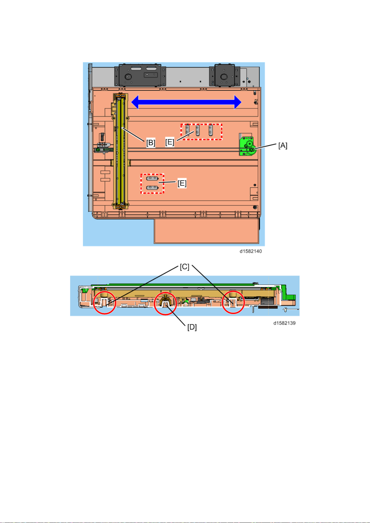
5.2 SCANNER DRIVE
Models D160, D161 and D170 are flat bed scanners using a CIS.
To s can an origi nal , the s canner motor (A ) moves the car riage on which the CIS (B ) is
mounted al ong th e car rier guide rail.
The CIS can be raised or lowered using the side guide rails (C) and adjusted relative to the
main scanning direction using the center guide rail (D). This is a factory adjustment; do not
do this in the field.
The size of th e original is detect ed by the AP S sen sor s (E) on t he bot tom fr ame.
D158/D159/D160/D161/D170 16 Detailed Descriptions
Page 22

[A]: All areas except China
[B]: China only
Scanner Drive
Detailed Descriptions 17 D158/D159/D160/D161/D170
Page 23
Overview
Name
A
Synchronization detect or mi rrors
B
Synchronization detect or lens
C
Mirror
D
F-thet a lens
E
Soundproof glass
F
Polygon Motor
G
Cylindrical lens
H
LD board
The LD drive board controls both the laser output and laser synchronization
mecha
The machine cuts off the power supply to the LD drive board if the front or right cover
is opened.
6. LASER EXPOSU RE
6.1 OVERVIEW
nism.
D158/D159/D160/D161/D170 18 Detailed Descriptions
Page 24
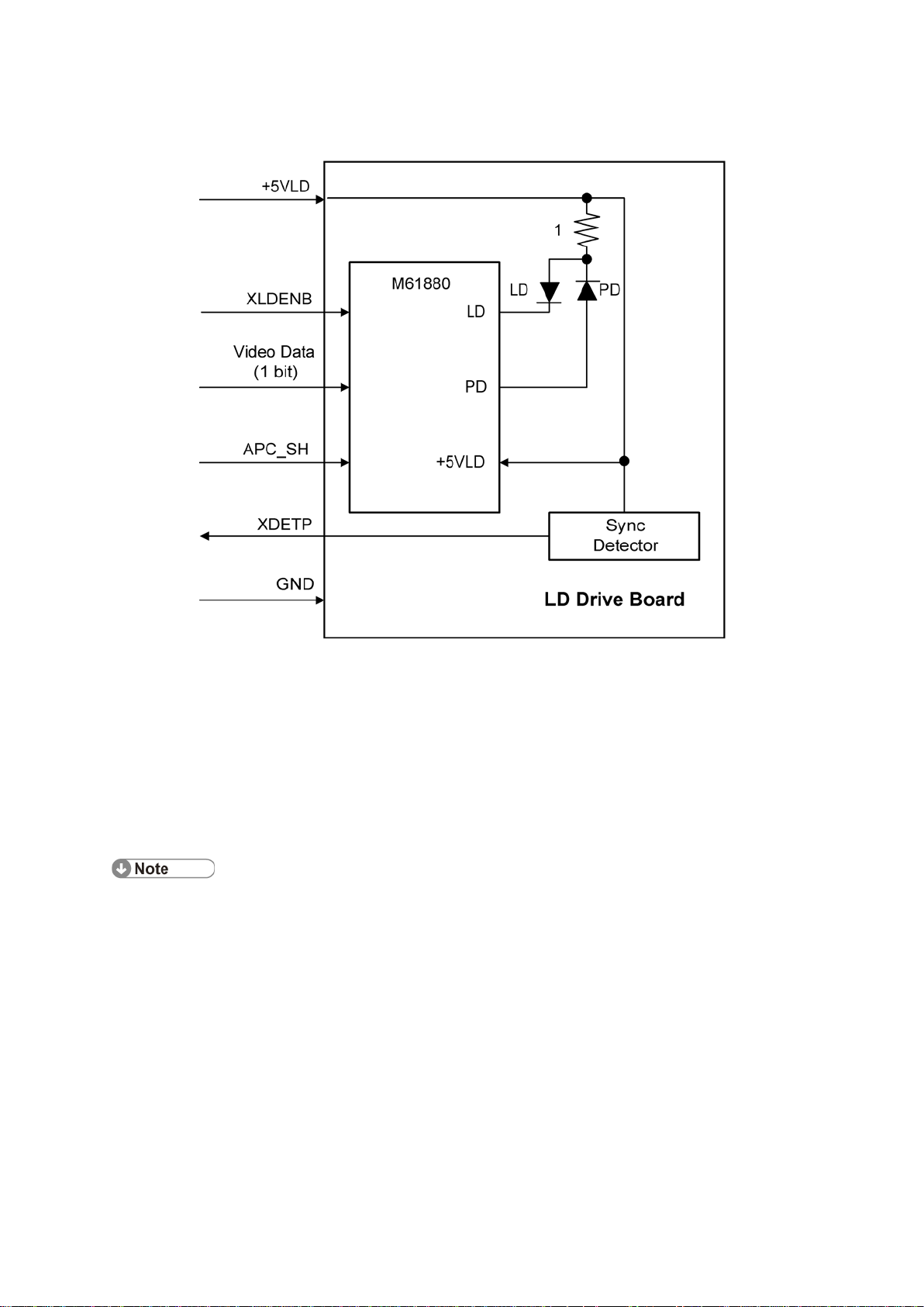
6.2 AUTO POWER CONT ROL (APC)
Do not touch the variable resistors on the LD unit in the field.
Auto Power Control (APC)
The LD driver IC drives the laser diode. To preven t the in ten sity of the laser b eam from
changing because of the temperature, the machine monitors the current passing through the
laser diode (LD). T he machine adjusts th e curr ent to the laser diode by compar in g i t with th e
re ference level from t he reference circuit.
This auto power c ont rol i s done jus t af ter th e machine i s turned on and during printing.
The laser diode power is adjus ted on the producti on lin e.
Detailed Descriptions 19 D158/D159/D160/D161/D170
Page 25

LD Safety Switch
6.3 LD SAFETY SWITCH
To ensure t echnician and us er s afety and to prevent the laser beam from inad ver tently
switching on during servicing, safety switc hes are located at the front and right covers. The
switches are installed on the +5VLD line through the BICU board.
Wh en th e f ront cover or th e ri ght cover is opened, th e power s upply t o th e laser diode is
interrupted.
D158/D159/D160/D161/D170 20 Detailed Descriptions
Page 26
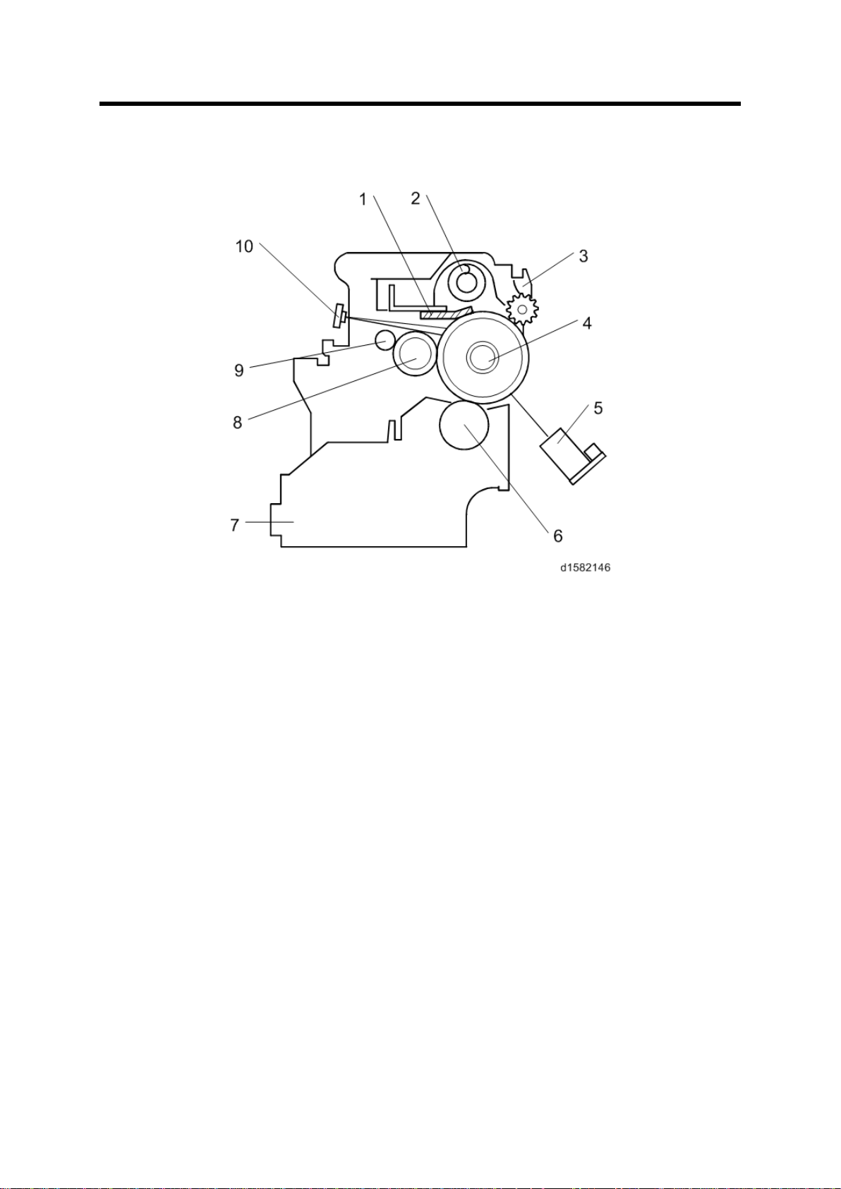
7. PHOTOCONDUCTOR UNIT (PCU)
1. Cleaning Blade
6. Dev elopment Rol ler
7.1 OVERVIEW
Overview
The PCU c onsists of th e components shown in t he above ill ustration. An organic
photoconductor (OPC) drum (diameter: 30 mm) is used in this machine.
2. Toner Collection Coil
3. Pick-of f Pawl
4. OPC Drum
5. ID Sensor (see note)
7. Dev elopment Unit
8. Charg e Roll er
9. Charge Roller Cleaning Brush
10. Quenching Lamp (see note)
Detailed Descriptions 21 D158/D159/D160/D161/D170
Page 27
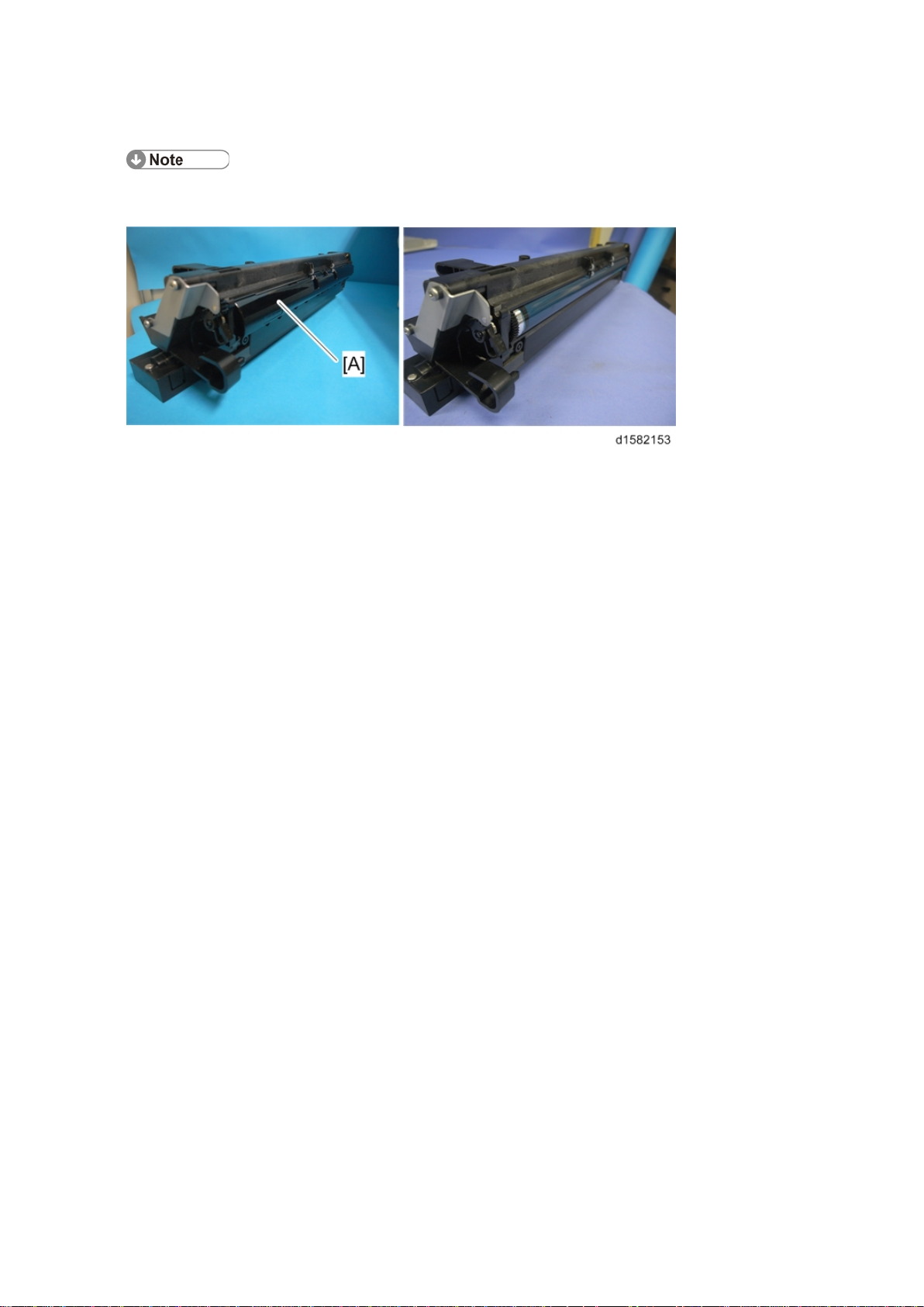
Overview
The ID sensor and quenching lamp are not included in the PCU.
The OPC drum's shutter [A] of
the previous model has been removed.
D158/D159/D160/D161/D170 22 Detailed Descriptions
Page 28
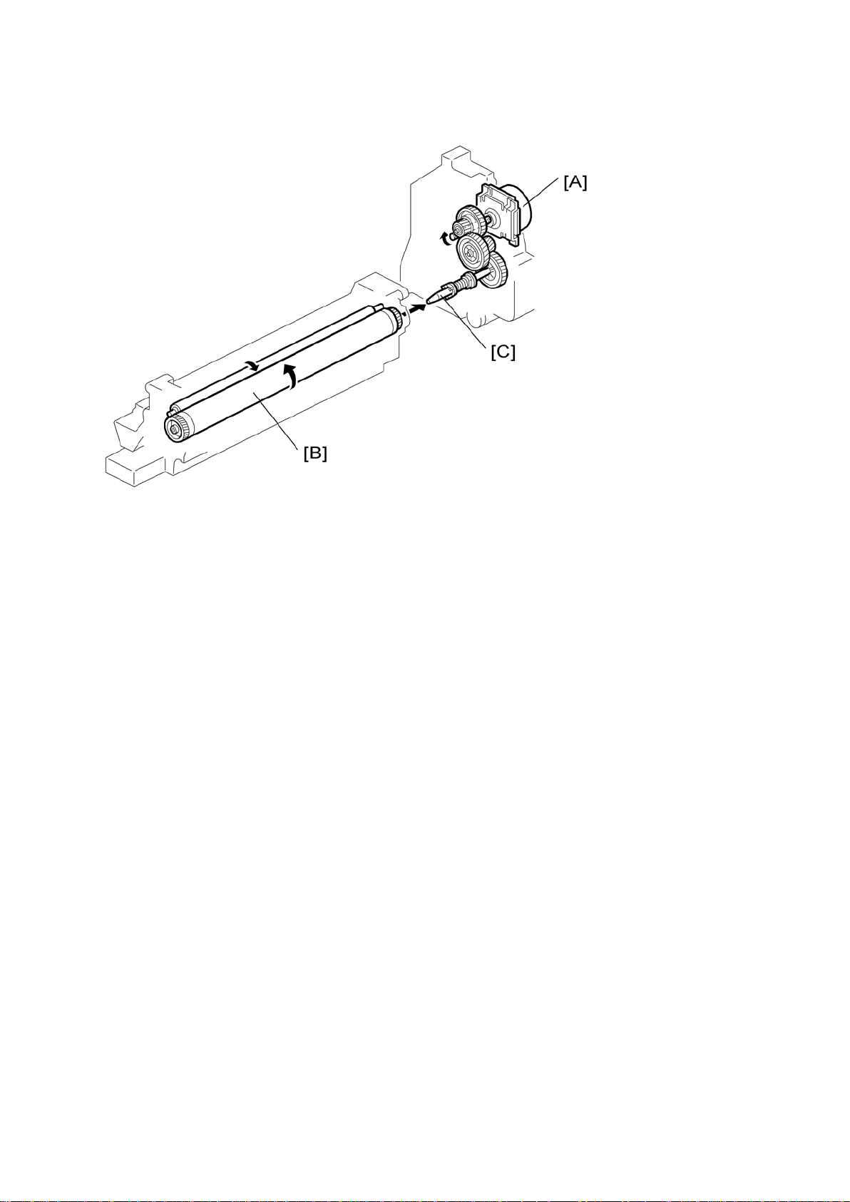
7.2 DRIVE
Drive
The main m otor [A] dr ives t he drum [B] through a s eries of ge ars and th e drum drive s haft
[C] . Th e mai n m otor ass embly inc lu des a d rive c ontr oller, which outputs a motor l ock s ig nal
w hen the rot ation sp eed is out of th e specified range.
Detailed Descriptions 23 D158/D159/D160/D161/D170
Page 29
Overview
8. DRUM CHARGE
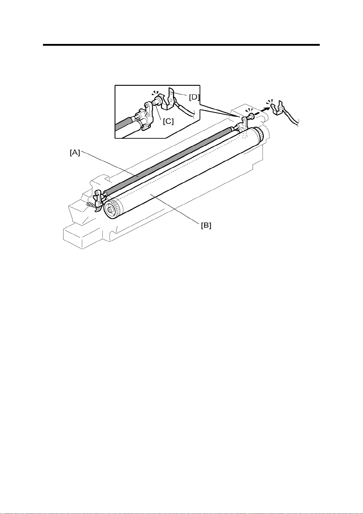
8.1 OVERVIEW
This cop ier uses a drum ch arge roll er t o charge the drum. The drum c harge roller [A] alway s
cont acts th e surface of th e drum [B ] to gi v e it a negat ive c harge of –950 V.
The high voltage supply board gives a negat ive c harge of –1700 V t o the drum charge roller
through the screw [C] and terminal plate [D]. This voltage can be changed using SP2-001001 (Charge Roll er Bias Adjust Setting (Copying)).
D158/D159/D160/D161/D170 24 Detailed Descriptions
Page 30

ID Sensor Pattern Production Timing
8.2 ID SENSOR PATTERN PRODUCTION TIMING
The ID sen sor pattern is not made every page or every job.
It is only made in the following conditions:
During warm -u p at power on
W hen t he m ach in e st art s war ming up from energ y s aver mode and th e temper atu re
is less t han th e target temp erat ure as set w i th SP Mode.
When the machine start s war ming up from en ergy saver mode and t he machine
prints more than 100 prints after generating the p-pattern.
Detailed Descriptions 25 D158/D159/D160/D161/D170
Page 31

Drum Charge Roller Cleaning
8.3 DRUM CHARGE ROLLER CLEANING
Becau se th e dru m charge roller [A ] alway s c ont acts th e drum, it get s dirty easil y. So, t he
cleaning brus h [ B] also con tacts the drum char ge roller all th e time to c lean t he surface of
the drum charg e roller .
D158/D159/D160/D161/D170 26 Detailed Descriptions
Page 32

9. DEVELOPMENT
9.1 OVERVIEW
Overview
The develop ment unit c onsists of th e following part s.
1. Develop ment roller
2. Mixing auger 2
3. TD sen sor
4. Mixing auger 1
5. Doctor b lade
This machine uses a single-r oll er dev elopment s ystem. T wo mi xing augers mix the
developer. The toner densit y (TD) sen sor and imag e densit y (ID) sen sor (see the illustration
in the P CU section) are us ed t o con tr ol the i mage density on the copy.
Detailed Descriptions 27 D158/D159/D160/D161/D170
Page 33

Drive
9.2 DRIVE
The main motor [A] drives the development roller [B] and mixing augers [C] through a train of
gears and the development drive shaft [D]. When the PCU is pushed in, the developm ent
dr ive s haft engages th e dev elopment roller gear.
The develop ment drive gear s (except for t he gears in the development unit) are helic al
ge ars. T hes e gears are quieter than normal gears.
D158/D159/D160/D161/D170 28 Detailed Descriptions
Page 34

9.3 DEVELOPER MIXING
Devel op er Mi xi ng
The two m ixi ng augers , [A , B] k eep t he developer even ly mixed . Mixing auger 2 [A]
trans port s excess developer, s cr aped of f the development roller [ C] by t he doctor blade [D ],
towards th e f ront of the machin e. Mixing auger 1 [B] ret urns the exc ess dev elop er, along
w ith new ton er, to the rear of th e mixing assemb ly. Here t he developer is reapplied to the
develop ment roller.
Detailed Descriptions 29 D158/D159/D160/D161/D170
Page 35

Development Bias
9.4 DEVELOPMENT BIAS
This mach in e uses a negative-positive d evelopment s ystem, in which black areas of the
laten t image are at a low negat ive charg e (about –154 ± 50 V) and white areas are at a high
negative ch arge (abou t –950 V).
To attract negativel y c harged t oner to the black areas of the latent image on the drum, the
high voltage supply board applies a bias of –650 volts t o th e development rollers throughout
the imag e development p rocess. The bias is applied to the development r oller s haf t [A ]
through the drive sha ft [B].
The develop ment bias v oltage (–650 V) can be adjusted with SP 2201 1.
D158/D159/D160/D161/D170 30 Detailed Descriptions
Page 36

9.5 TONER SUPPLY
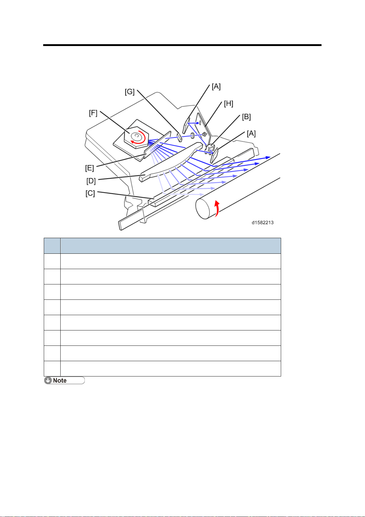
9.5.1 TONER BOTTLE REPLENISHMENT MECHANISM
Tone r Supply
W hen a toner bottle is placed in the bottle holder unit [A] and the unit is pushed in
completely, t oner sh ut ter [B] moves again st th e side [ C] of the PCU. When the toner bottle
holder lever [D] is put back in the original position, the cap [E] on the toner bottle is pulled
away and kept in place by the chuck [F].
The toner su pply mechanism trans port s t oner from the bottl e to the dev elop ment unit. Th e
toner bottle has a spiral groove [G] that helps move toner to the development unit.
To add a new t oner bottle, fir st lift th e ton er bottle hol der. When this is done, the c huc k
rele ases th e tone r bottl e cap in to it s pr oper pos iti on t o prev ent toner from scat ter in g.
Then, when t he bottle hol der unit is pull ed out to add a new toner bot tle, th e ton er shutter
shuts to block the opening as a result of pressure from a spring.
Detailed Descriptions 31 D158/D159/D160/D161/D170
Page 37

Tone r Supply Mechanism
9.6 TONER SUPPLY MECHANISM
The toner su pply motor [A] d ri v es t he ton er bot tle [ B] and th e mylar blades [C]. Firs t , t he
toner f all s down in to the ton er bottle hol der. The toner sup pl y mylar blades transfer th e toner
to the slit [D]. When the PCU is installed in the machi ne, the shutter [E] above the PCU is
op ened by th e toner bottle h older. Then t he t oner f all s down in to the dev elopmen t unit
through the slit and the shutter.
D158/D159/D160/D161/D170 32 Detailed Descriptions
Page 38

Toner Density Control
Mode
Sensor control 1 (SP 2921, “0”): Normally use this setti ng only
Toner supply
Comp are Vt with a r efe rence v oltage (Vt s or Vref )
Toner cont rol
Toner is supplied to the development unit when Vt is higher than
9.7 TONER DENSITY CONTROL
9.7.1 OVERVIEW
Ther e are four modes for cont rolling toner su pply as shown in t he following tables , whic h can
be changed with by SP 2921. The factory setting is s ensor contr ol 1 mode.
Basically, th e ton er concen tration i n t he developer is cont rolled using t he standard TD
sensor v oltage ( Vts), t oner s uppl y r eferen ce voltage (Vr ef) , actual TD sen sor output voltage
(Vt), and ID sensor output data (Vsp/Vsg).
The four-toner densit y c ont rol modes ar e as follows .
Se nsor c ontr ol 1
decision
process
the ref erenc e volt age (V ts or V ref) . This mode ke eps th e Vr ef
val ue for us e with t he next t oner dens ity con tr ol.
Vts i s us ed fo r t he firs t toner dens ity con tr ol aft er a new PC U
has been installed, until i t h as been c orrec ted with the I D sensor
output.
Vref is u sed after Vts has b een cor rected with the ID sens or
output voltage ( cor rected during th e f ir st ton er dens ity contr ol for
a new P CU).
Detailed Descriptions 33 D158/D159/D160/D161/D170
Page 39

Toner Density Control
Toner supply
Varies
Toner end detect ion
Performed
Sensor control 2 (SP 2921, “1”): For designer’s use only; do not
Toner supply
Comp are Vt with a r efe rence v oltage (Vt s)
Toner cont rol
This toner con tr ol p roces s is the s ame as s ensor control 1
Toner supply
Varies
Toner end detect ion
Performed
Fixed control 1 (SP 2921, “2”): For designer’s use only; do not
Toner supply
Comp are Vt with a r efe rence v oltage (Vt s or Vref)
Toner cont rol
This toner con tr ol p roces s is the s ame as s ensor control 1
Toner supply
Fixed (SP 2925)
Toner end detect ion
Performed
amount
Se nsor c ontr ol 2
Mode
decision
process
amount
Fixed control 1
Mode
decision
use in th e f ield
mode. However , the reference voltage used is always Vts.
use in th e f ield
process
mode.
amount
D158/D159/D160/D161/D170 34 Detailed Descriptions
Page 40

Fixed control 2
Fixed control 2 (SP 2921, “3”): Use t emp orarily if th e TD sensor
Toner supply
None
Toner cont rol
Toner is supplied every p rint ed page regar dless of Vt.
Toner supply
Fixed (SP 2925)
Toner end detect ion
Not performed
Toner Density Control
Mode
decision
process
amount
ne eds to be replaced
9.7.2 TONER DENSITY SENSOR INITIAL SETTING
The TD sen sor in itial setti ng (SP2-801-0 01 D eveloper In itializati on) pr ocedu re mu st be done
after replacing th e developer. During TD sens or initial setti ng, the T D s ensor is set s o that
the TD sensor output is the value of SP 2926 (default: 2.5V) . Thi s value will be us ed as the
standar d ref erenc e volt age (V ts) of the TD sens or.
9.7.3 TONER CONCENTRATION MEASUREMENT
The toner c oncentration in the d eveloper is detect ed once ev ery copy cycl e. The sen sor
output voltage (Vt) during the detection cycl e is compared with the stan dard ref erence
vol tage (Vt s) or th e toner s upply r eferen ce voltage (Vr ef ).
9.7.4 VSP/VSG DETECTION
The ID sen sor detects th e followi ng v oltages.
Vsg: The ID sensor output when checking the drum surface
Vsp: The ID sensor output when checking th e ID sensor pat ter n
In th is way, the r eflec tivit y of b oth th e drum surface and t he pat ter n on th e drum are
checked , com pensati ng f or any variation s in t he ref lectivit y of the pattern on th e drum or the
re f lect iv ity of th e drum surface.
The ID sen sor pattern is made on t he drum by the char ge roller and laser d iode.
Vsp/V sg is not d etected every pag e or job ; it i s detect ed at the fol lowi ng times to deci de V ref.
During warm-up at p ower on
If the machine starts warmi ng up when the fusing temperature is 30°C or less (default) after
entering night mode or low power mode (SP 2994 specifies the temperature setting).
Detailed Descriptions 35 D158/D159/D160/D161/D170
Page 41

Toner Density Control
Value of SP2-925
Motor On Time (t = 200 ms)
0 T 1
2t 2 4t 3 8t 4 12t 5 16t
6
Continuously
7
Not supplied
9.7.5 TONER SUPPLY REFERENCE VOLTAGE (VREF)
DETERMINATION
The toner su pply reference volt age (Vref ) i s us ed f or t oner s upply determinat ion (s ee below).
Vref is det erm i ned using the foll owi ng data:
ID sensor output (V sp/Vsg)
(Vts or the current Vref) - Vt
9.7.6 TONER SUPPLY DETERMINATION
The re feren ce vol tage ( Vts or Vref) is th e th reshold volt age for deter min in g whet her or not to
supply ton er. If Vt bec omes greater than th e ref erenc e volt age, the machine supplies
add itional toner.
This can be checked using SP 2220.
9.7.7 TONER SUPPLY MOTOR ON TIME DETERMINATIONS
For fixed control mode, the toner supply motor on time is specified by the setting of SP 2925,
and does not vary. The default setting is 200 ms for each copy. The toner supply motor on
ti me for eac h value of SP 2925 is as f ollows .
For sens or c ontrol modes 1 and 2, the toner supply motor on time is decided by the following
factors.
Vt
Vref or V ts
TD sensor sen sitivit y (coeffic ien t: S, value i s 0.4)
D158/D159/D160/D161/D170 36 Detailed Descriptions
Page 42

Toner Density Control
Level
Decision
Motor On Time (seconds)
1
(Vts or Vref) < Vt ≤ (Vts or Vref) + S/16
t (0.4)
2
(Vts or Vref) < Vt ≤ (Vts or Vref) + S/8
t x 2 (0.8)
3
(Vts or Vref) < Vt ≤ (Vts or Vref) + S/4
t x 4 (1.6)
4
(Vts or Vref) < Vt ≤ (Vts or Vref) + S/2
t x 8 (3.2)
5
(Vts or Vref) < Vt ≤ (Vts or Vref) + 4S/5
t x 16 (6.4)
6
Vt ≥ (Vts or Vref ) + 4S /1 6 (near-end)
T (30); see note 3
7
Vt ≥ (Vts or Vref ) + S ( ton er end)
T (30); see note 3
The value of “t” can be changed using SP 2922 (default: 0.4 second)
The value of “T” can be changed using SP 292
T (30) means that toner is supplied intermittently in a 1/3 duty cycl e (1 s on, 2 s off) for
30 seconds
Ther e are seven levels for toner supply motor on t i me as shown bel ow.
3 (default: 30 seconds)
Detailed Descriptions 37 D158/D159/D160/D161/D170
Page 43

Toner Supply in Abnormal Sensor Conditions
9.8 TONER SUPPLY IN ABNORM AL SENSOR
CONDITIONS
9.8.1 ID SENSOR
Re adings are ab normal if any of the f ollowing con ditions oc cu r:
Vsg ≤ 2.5V
Vsg < 3.5V when maximum power (979) is applied
Vsp ≥ 2.5V
(Vsg – Vsp) < 1.0V
Vt ≥ 4.5V or V t ≤ 0.2V
The above ID sensor values can be checked using SP 2221.
Wh en th is i s detec ted , the machine changes th e value of Vref to 2.5 V then does the toner
den sity cont rol proc ess ( in a s imil ar way to sen sor c ont rol mode 2 ).
No SC code is generat ed if t he I D sen sor is defective.
9.8.2 TD SENSOR
The TD sen sor outp ut is checked every copy. If t he readings from the TD sensor become
abnormal, the mach in e ch anges t he t oner dens ity contr ol mode to fixed s upply mode 2, and
the toner supply amount per page is always 200 m s, regardless of the value of SP 2925. If
the m ach in e det ects th e TD sensor error c ondition 10 t i mes con secu tively, an SC cod e is
generated (SC390) and the machine must be repaired.
9.9 TONER NEAR END/END DETECTION AND RECOVERY
The toner near end and end c onditions are detected using th e Vt and Vr ef values, i n a
si milar way to t oner densit y cont rol.
This is don e in all ton er supply m odes except for fixed mode 2, when toner end is not
detected.
9.9.1 TONER NEAR END DETECTION
If Vt is at level 6 (see the tab le on t he prev ious page) f ive t imes con sec ut iv ely, th e machi ne
enters the toner near end condition and the toner end indicator starts blinking. T hen the
mac hin e s uppl ies toner for a c ert ain time, w hich depends on t he s etti ng of SP 29 23 (see the
pr evious page).
D158/D159/D160/D161/D170 38 Detailed Descriptions
Page 44

Toner Near End/End Detection and Recovery
9.9.2 TONER NEAR END RECOVERY
If the mach in e det ects “Vt < (Vr ef or V ts ) + 4S/5” t wice consec utively in any of the following
situations, the machine clears the toner near end condition.
While i n t he t oner recovery cy cle (sup pl ying ton er on and off for 30 sec onds ) after t he
mac hin e has detec ted a toner near en d condition.
During copying in the toner near end condition.
If the fr ont c over is opened and c losed for more than 10 seconds while a toner near end
condition exists.
9.9.3 TONER END DETECTION
Ther e are two situati ons for enter in g t he t oner end con dition.
Wh en V t is level 7 th ree times c onsecu tively, t he m ach in e ent ers the ton er end c ondition.
W hen 50 copies have been made since entering the toner near end condition. The
number o f c opies bet ween toner near-end and toner end can be changed using SP
2213.
9.9.4 TONER END RECOVERY
While t urning on t he m ain switch, if the fron t cover is opened for 10 secon ds or more and
then closed while a T oner E nd con di tion exis ts (following ton er bottle replacement) , the
mac hin e clears th e Ton er E nd c ondition. Th e rec overy procedu re is the same as for toner
ne ar end. It takes about two mi nut es.
Detailed Descriptions 39 D158/D159/D160/D161/D170
Page 45

Drum Cleaning
10. DRUM CLEANING AND TONER RECYCLING
10.1 DRUM CLEANING
The c leanin g blade [ A] removes any toner remainin g on th e drum af ter the image is
trans ferred to the paper. T his model uses a count er blade system.
The cleaning blade scrapes off toner remaining on the drum . When toner builds up in the
clean ing uni t, ton er at the top of the pile is removed by the toner collection c oil [B].
To r emov e th e toner and other part icl es that are accumu lated at the edge o f t he c lean ing
blade, the dr um turns in r ever se for about 5 m m at th e end of every copy job.
D158/D159/D160/D161/D170 40 Detailed Descriptions
Page 46

10.2 TONER RECYCLING
Toner Recycling
Toner pi ck ed up by th e ton er c ollec tion coil [A], is t rans port ed t o the op eni ng [B] in t he side
of t he P CU. T hen, thi s t oner fal ls in to the dev elopment unit w i th new ton er c oming from th e
toner bottle and it is all mixed together by mixing auger 1 [C] and used again.
Detailed Descriptions 41 D158/D159/D160/D161/D170
Page 47

Overview
1. Tray H eater
6. By-pass Feed Roller
11. PAPER FEED
11.1 OVERVIEW
There are one or tw o paper trays, each of which can hold 250 sheets.
The paper tr ay feed stations us e a fr ict ion pad s ystem. To prevent paper f rom get ting
caught inside the machine when the tray is pu lled ou t, the paper fe ed roller an d shaft d o
not separate f rom the tray w hen th e tr ay is pulled out.
The two relay s ensor s are used for paper jam detect ion. The lower one d etec ts jams
when paper is fed up from the optional paper feed unit.
The c ompon ent s of th e paper feed station are as follows.
2. Paper End Sensor
3. Pap er Feed Roller
4. Regist rat ion Roll er
5. Regist rat ion Sen sor
7. Upper Relay Sensor
8. Lower Relay Sen sor
9. Friction Pad
10.Tray Lift Sensor
11. Paper S ize Switch
D158/D159/D160/D161/D170 42 Detailed Descriptions
Page 48

11.2 PAPER FEED DRIVE MECHANISM
Paper Feed Drive Mec h anism
The main m otor [A] dr ives t he pick-up and feed mechanism of both the first and second
paper tr ays . The paper feed clutches [ B ] transfer drive f rom this mot or t o the p aper fe ed
rollers [C ].
Wh en th e paper f eed clutch t urns on , the feed roller starts to feed th e paper. T he paper feed
clu t ch s tay s on u ntil shortl y after t he regist rati on sensor has been activated.
Detailed Descriptions 43 D158/D159/D160/D161/D170
Page 49

Paper Feed an d S eparati on M ec h anism
11.3 PAPER FEED AND SEPARA TION MECHANISM
The paper feed roller [A] dri ves the top sheet of paper from t he paper tray to the cop ier. The
frict ion pad [B] al lows only one sh eet to feed at a time. The fric tion pad appli es press ure t o
the fe ed roller wi th a sprin g [ C].
The friction pad pressure cannot be adjusted.
D158/D159/D160/D161/D170 44 Detailed Descriptions
Page 50

11.4 PAPER LIFT MECHANISM
[A] Botto m plate
[B
[C] Bottom plate lift gear
[D] Tr ay lif t mo tor
[E] Bottom plate lift HP sensor
] B ottom pl ate lift arm
Paper Lift Mechanism
The tray li f t mot or rotates the gear [ C] and th e gear makes th e rack [F] move.
The movement of the rack pull s the spring and thi s moves the bot tom plate li ft arm [B].
The arm li f ts the b ottom pl ate [A].
The pos ition of th e bottom p late is detect ed by the bottom pl ate lif t H P sen sor [E]. T his
mac hin e does not u se mot or control to detect the bottom plate position.
Detailed Descriptions 45 D158/D159/D160/D161/D170
Page 51

By-pass t r ay b ot t om pl ate lift mechanism
[A] By -pass tra y bottom plate
[B] Pressure spring
[C] By
[D] A ctu ato r
[E] By
[F] By
11.5 BY-PASS TRAY BOTTOM PLATE LIFT MECHANISM
-pass tr ay bot tom plat e lift c am HP sen sor
-pass tray bottom plate lifting up cam (Front and rear)
-pass tr ay bottom plate lifting up cam clutch
The paper tr ansp ort motor rotates th e by-p ass tray bottom plate lift cam clutch [F], and this
moves the by -pas s tray bot tom plate [A] up and dow n.
The pos ition of th e by-pa ss tray b ottom plat e li ft cams ( and bec ause of this, the by-pass tray
bott om plat e) is detect ed by the by -pas s t ray bott om plate lif t cam H P sen sor . [C].
D158/D159/D160/D161/D170 46 Detailed Descriptions
Page 52

Paper End Detection
11.6 PAPER END DETECTION
If there is an y pap er i n t he paper tray, the paper stac k lifts t he fe eler, t he paper en d sensor
[A ] is deactivated .
Wh en th e paper tray ru ns out of p aper, th e paper end fe eler d rops into the cuto ut [B] in th e
tray b ottom p late and t he pape r end s ensor is activated .
W hen the paper tray is drawn out with no paper in the tray, the shape of the paper end feeler
causes it to lif t up .
Detailed Descriptions 47 D158/D159/D160/D161/D170
Page 53

Paper Size Detection
Models
Switch Location
North America
Europe/Asia
SW4
SW3
SW2
DLT (A3) SEF*
1
A3 (DLT) SEF*
1
0 0 1
LG (B4) SEF*
2
B4 (L G) SEF *
2
0 0 0
A4 SEF
A4 SEF
1 1 0
LT SE F
LT SE F
1 1 1
B5 SEF
B5 SEF
0 1 1
LT (A4) LEF*
3
A4 (LT) LEF*
3
1 0 0
Exe (B5) LEF*
4
B5 (Exe) LEF*
4
0 1 0
A5 LEF
A5 LEF 1 0
1
11.7 PAPER SIZE DETECTION
11.7.1 PAPER TRAY
Ther e is no size swi t ch for tr ay 1. T he paper s ize is fix ed at either A4 or LT (LEF for b oth
sizes). You can change the size setting with SP5-181-1.
For tr ay 2, there are four paper size switches [ A ] w orking in combination. Switch 1 (right en d)
is for tray set detect ion. The oth er three swit ches detect t he paper size as shown in the table
below. The actu ator [B] i s moved by the end p late [C ].
0: Pushed, 1: Not pushed
D158/D159/D160/D161/D170 48 Detailed Descriptions
Page 54

Paper Size Detection
*1 : The machine detects eit her D LT SEF or A3 SEF, dependi ng on the set ting of
3.
*2: The machine detects either LG SEF or B4 SEF, depending on the setting of SP5
*3 : The machine detects eit her L T L EF or A4 LE F, depending on the setting of SP5
*4 : The machine detects eit her Exe LE F or B5 LEF, dependi ng on t he s
SP 5
SP5-181-
-181-4.
-181-2.
etting of SP5-181-5
-181-6 t o –19 doe s similar f uncti ons for t he opt ional paper trays.
The mac hi ne disables paper feed from a tray if the paper size cannot b e det ected (i f th e
paper size actuator is b rok en or no tray is inst all ed).
For non-standard paper sizes , if they are not visib le on th e user tool screen for select ing
paper sizes , then set SP5-112-001 (Non-St andard Paper Selection) to "1". If th e user s elects
on e of these s izes, auto paper size selection is disabled.
Detailed Descriptions 49 D158/D159/D160/D161/D170
Page 55

Paper Size Detection
CN No. (BICU)
11" x 17"
81/2" x 14"
51/2" x 81/2"
CN136-1
ON/OFF
OFF
OFF
OFF
OFF
CN136-2
OFF
OFF
OFF
ON
OFF
CN136-3 (GND)
OFF
OFF
OFF
OFF
OFF
CN136-4
OFF
ON
OFF
OFF
ON
CN136-5
ON
ON
OFF
OFF
OFF
CN No. (BICU)
A3
A4 SEF
8" x 13"
A5 SEF
CN136-1
ON/OFF
OFF
OFF
OFF
CN136-2
OFF
OFF
OFF
ON/OFF
CN136-3 (GND)
OFF
OFF
OFF
OFF
CN136-4
OFF
ON
ON
OFF
CN136-5
ON
ON
OFF
OFF
11.7.2 BY-PASS TRAY
The by-pass feed paper size switc h [ A] monitors the paper width. Th e s id e fen ce is
connected to the ter minal pl ate g ear. When the s ide fen ces move to mat ch th e paper width,
the c ircular ter minal pl ate r otates over the w irin g patterns on th e rectangular part of the
paper size switc h. The patterns for each paper width in the paper size switch are unique.
North Amer ica
Europe/Asia
D158/D159/D160/D161/D170 50 Detailed Descriptions
Page 56

Side Fences
11.8 SIDE FENCES
If the tray is full of paper and it is pushed in strongly, the fences may deform or bend. This
may cause t he paper to s kew or th e side-to-side reg istrati on t o be incorrect. To correc t this,
each side f ence ha s a stopper [A] att ach ed to it . Each side f enc e can be secured with a
screw, for custom ers who do not want to change the paper s ize.
Detailed Descriptions 51 D158/D159/D160/D161/D170
Page 57

Paper Registration
11.9 PAPER R E GI STRATION
The dr ive fr om the m ain motor [A] is tr ansmi tted to the regist rat ion r oller th rough the
reg istration clutch gear [B].
The reg istrati on s ensor [C] is u sed for correcting paper skew and for detecting paper
misfeeds.
The c leanin g mylar [D ] con tacts the registration roller. It r emoves paper du st from th e
registration roller so that this dust will not transfer into the development unit through the
drum-cleaning unit.
The amount of paper buc kle at the registration roller to correct sk ew can be adjust ed with
SP1-003 ( Pap er B uckle).
If jams frequent ly occur after regist ration, S P1-90 3 (Feed Cl Re-en ergize) can be used to
activate the relay clut ch so that the relay r oller assists the registration roller i n fe eding th e
paper along. When feeding from the by-pass tray, the by-pass fe ed clutch i s ac tivated,
turning the by-pass feed roller. This feature may be needed when feeding thick paper, and
cannot be used for the first paper feed tray.
D158/D159/D160/D161/D170 52 Detailed Descriptions
Page 58

Overview
12. IMAGE TRANSFER AND P APER SEPARATIO N
12.1 OVERVIEW
The transfer roller [A ] touches th e sur face of th e drum [B ] . The high volt age supply b oard
suppli es a posit ive c urrent to t he t rans fer roll er, whic h attracts t he t oner from the drum onto
the paper. Th e cu rrent depends on th e paper w id th, paper type, and paper feed tr ay.
The c urv atu re of the dr um and the d ischarg e pl ate [C] hel p th e paper to separate from t he
drum. The discharge plate is grounded.
Drive fr om the drum throu gh a gear [D] tu rns th e tr ansfer roll er.
Detailed Descriptions 53 D158/D159/D160/D161/D170
Page 59

Image Transfer Current Timing
Paper Tray/
By-pass Tray
A3/A4 LEF
11 µA
12 µA
13 µA
12 µA
17 µA
DLT
12 µA
18 µA
15 µA
18 µA
17 µA
B4 SEF
12 µA
12 µA
15 µA
12 µA
18 µA
LT SE F
17 µA
17 µA
15 µA
17 µA
24 µA
A4 SEF
21 µA
15 µA
28 µA
15 µA
24 µA
B5 SEF
22 µA
19 µA
28 µA
19 µA
22 µA
A5 SEF
22 µA
19 µA
28 µA
19 µA
28 µA
HLT SEF
22 µA
19 µA
28 µA
—
—
B6 SEF
22 µA
19 µA
28 µA
—
—
A6 SEF
22 µA
19 µA
34 µA
—
—
Post card/
12.2 IMAGE TRANSFER CURRENT TIMING
Ther e are two tran sf er cu rrent levels: low and high. The image transfer pr oced ure is as
follows:
6. When the CPU rec eives th e imag e writ in g start s ignal , the CPU i nstructs t he hi gh
voltage supply board to supply +10 microamperes (low transfer current level) to the
roller. T hi s pr event s any pos itively c harged t oner on the drum surf ace f rom
trans ferr in g t o th e tr ansfer roller .
7. At a certain time after t he low t ransf er c urrent has been s upplied to t he rolle r, high
trans fer current is appli ed t o th e rol ler t o tr ansf er t he t oner t o th e paper (see t he
tabl e below).
8. After th e tr ailing edge of the paper has passed through the roller, transfer current
turns off. In multipl e c opy mode, the t ransf er c urrent shift s ag ain to the low tr ansfer
current.
The high transfer current levels (default) are as shown in the followi ng table. With SP 2301,
the high transfer current level used for the paper feed trays, duplex tray, by-pas s t ray, and
cleaning an be adjusted.
By-pass Tray
(Thick/OHP)
By-pass Tray
(Normal)
(Special/
Envelope)
Duplex
(1st Side)
Duplex
(2nd Side)
Envelope
D158/D159/D160/D161/D170 54 Detailed Descriptions
22 µA 19 µA 34 µA — —
Page 60

Transfer Roller Cleaning
Be careful when increasing the transfer current. This may cause a ghosting effect, in which
par t o f the image at the top of the page is repe ated lower down the page at a lower dens ity.
In th e worst c ase, it may also damage th e OP C drum.
12.3 TRANSFER ROLLER CLEANING
If the pap er size is smaller than th e image, or if a paper jam occurs d uring printing, toner
may b e tr ansferred t o th e roller sur face. To prev ent the toner from transf erring to the b ack
side of the printouts, the transfer roller requires cleaning before the next printi ng run.
During transfer roller cleaning, the high voltage supply unit supplies a negati ve cleaning
voltage (about –1 k V) t o th e tr ansfer roller . Any neg atively ch arged toner on t he t rans fer
roller is then transferred back to the drum. Then a positive cleaning current (+10
microamperes) is appli ed t o th e tr ansf er r oller to push b ack to the drum any posit ively
charged tone r on th e tr ansfer roller .
The machine goes through the cleaning mode in the following conditi ons:
Before starting the printing j ob (only if enabled with SP 2996; note that the default
sett ing i s off).
Just af ter the power is swi t ched on.
After a copy jam has been cleared.
After 10 or more she ets of paper have b een cop ied and t he copy job has fin ished.
Also, the transfer roller cleaning current can be adjusted using SP 2301 4.
Detailed Descriptions 55 D158/D159/D160/D161/D170
Page 61

Paper Separation Mechanism
12.4 PAPER SEPARATION MEC HANISM
The discharge plate [ A] and t he dr um c urv atu re of th e drum help th e paper t o separate away
from the drum. The discharge plate is grounded.
D158/D159/D160/D161/D170 56 Detailed Descriptions
Page 62

13. IMAGE FUSING AND PAPER EX IT
1. Paper exit roller
6. Fusing lamps
13.1 OVERVIEW
Overview
2. Exit sensor
3. Hot roller s tr ippers
4. Pressure roller
5. Pressure spring
7. Thermistor
8. Thermostat
9. Hot roller
Detailed Descriptions 57 D158/D159/D160/D161/D170
Page 63

Fusing Unit Dri v e and Rel eas e M ec h ani sm
13.2 FUSING UNIT DRIVE AND RELEASE MECHANISM
13.2.1 FUSING UNIT DRIVE
The main motor [C] drives the fusing unit through a gear train, and drives the paper exit
rollers [A] through the timing belt [B].
13.2.2 DRIVE RELEASE MECHANISM
W hen the right door [I] is open, the spring [G] pushes the top end of the gear holder [F] to
the right. The drive gear is released from the fusing-unit drive gear [J]. When you close the
right door, the m echanical link [H] pushes the spring [G]. The gear holder turns
counter clockwi se by th e force of another s prin g [ D] , and engages wi t h the fusing-unit drive
gear.
D158/D159/D160/D161/D170 58 Detailed Descriptions
Page 64

Fusing Unit Drive and Release Mechanism
Fusing Temp.
Contact/Release
18°C or higher
Release
Less than 18°C
Contact
Solenoid
Drive gear
Off
Engaged
On
Released
13.2.3 CONTACT/RELEASE CONTROL
The drive power is not transmitted to the fusing unit during warming up when the fusing
temperature (at the start) is 18°C or higher. The drive power is transmitted when the fusing
temper atu re is less th an 18°C. Th is contact /r elease con trol is based on the followin g
conditions.
The hot roller [L ] takes a shorter t i me to bec ome hot enough if it is not turning during
w armin g up. W hen, however, the fusing t emper atu re (at th e start) is low , the temperat ure of
the hot-rol ler surface may bec ome uneven.
You can disable this control (SP1103 1).
13.2.4 DRIVE RELEASE SOLENOID
The fus in g dr iv e releas e solenoid [E] is on the rear end of the g ear holder. When th e
solenoid is off, the spring [D] pulls the gear holder, and the drive gear engages with the
fusing unit drive gear. When the solenoid is on, it pulls the top end of the gear hol der t o th e
right, and the gear holder turns clockwise. As a result, the drive gear is released from the
fusing unit drive gear.
The releas e solenoid comes on wh en you tu rn on t he m ain sw i tc h if th e f using t emp eratu re
is 18°C or higher. T he solenoid rel eases the drive gear from the fusing unit drive gear. The
fusing lamp s heat the h ot r oller [L] more ef fectively since the heat i s not conducted to the
pr ess ure r oller [K ]. When t he hot roller becomes hot enough, th e release so lenoi d tur ns of f ,
letting the drive gear engage with the fusing unit drive gear.
Detailed Descriptions 59 D158/D159/D160/D161/D170
Page 65

Fusing Entrance Guide Shift
13.3 FUSING ENTRANCE GUIDE SHIFT
The entrance guide [A] is adjustable for paper thickness to prevent creasing. The outer
screw h oles [B] on each side are used as the default setting.
If creasing occ urs frequently in the fusing unit, adjust the entrance guide to the right, by
securing it with t he i nner holes [C ]. This all ows more direct acc ess to t he gap bet ween the
hot roller and the press ure r oller.
13.4 PRESSURE ROLLER
The pressure springs [A] constantly apply pressure between the hot roller [B] and the
pressure roller [C]. Applied pressure can be changed by adjusting t he position of the
pressure springs. The spring is positioned at the end [D] as the default setting.
D158/D159/D160/D161/D170 60 Detailed Descriptions
Page 66

Fusing Temperature Control
13.5 FUSING TEMPERATURE CONTROL
13.5.1 OVERVIEW
Ther e are two fusing lamps ( not identical), t wo th ermis tor s, and f our t hermost ats .
The fusing temperatur e is controlled using the thermistors [A].
The CPU checks the output from the fusing thermistor once every 1.5 seconds. The CPU
decides how long the lam ps must be switched on during the next 1.5 seconds by comparing
the following t emp erat ures:
The cen ter th ermi st or t emper atu re and the tar get center temperature
The end thermi st or t emper atu re and the tar get en d temperature
The fusing lamp works to maintain a target fusing temperature of 160°C during copying.
Detailed Descriptions 61 D158/D159/D160/D161/D170
Page 67

Fusing Temperature Control
13.5.2 TEMPERATURE CONTROL
Acc ording t o th e operat ion mod e, the fus in g t emp erature i s c ont rolled. T he diagram
illustrates the transition of fusing temperature. After you turn the main switch on, the fusing
temper atu re rises f rom the room t emper atu re (t 0) to one of the spec ifi ed temperatures. Y ou
can adjust some of the temperatures.
A1: Regular Start Mode/A2: Cold Start Mode (SP1-105-001, 002)
Turning the fusing lamp on and off may affect t he voltage of the powe r source i n th e room,
causing the fluorescent lights in the room to flicker. To lighten this problem, you can reduce
the checking repetit i on to 20 times.
Wh en machine in itial ization end s, th e fus ing temperat ure is set t o one of the following
temperatures:
The Standby Temperature (T2: SP 1105 3-4) when there is no print job.
The First Print Temperature when the copier has received a print request during
machine initialization.
You cannot directly adjust the First Print Temperature. This temperature is 10°C higher (up
to 185°C) than the Copying Temperature (
Copy Adjustments Printing/Scanning).
D158/D159/D160/D161/D170 62 Detailed Descriptions
Page 68

Fusing Temperature Control
C: Copying Mode
Wh en th e cop ier is making copies, the f using t emperatu re is s et to one of the following
temperatures:
The Warm Up Temperature (SP 1105 1-2) to out put the first print af ter th e Low
Power Mode (
The Copying Temperature (T4: SP 1105 5-6) t o output the second print (and after the
second)
You c an raise t he Warm Up Temp erat ure t o make better the fusing quality of the f irst p rint.
While t he copier is adjusti ng th e f using t emper atu re to the Warm Up Temper atu re, the
message "Copy starts after war m up " is displ ayed.
c : Thick Paper Mode
Wh en th e machine is makin g cop ies on th ick paper, the fusing t emper atu re is set to the
Thick Paper Temperature (SP 1105 9-10). When thick paper reaches the registration sensor,
the c opi er c hecks the fusing temperature, and e xec utes one of the fol low ing proces sing:
Copy Adjustments Printing/Scanning)
Stops feeding the thick paper (and keeps it at the registration sensor) and waits for
the fusing temperature to reach the predefined temperature–the temperature 5°C
lower th an t he T hick Paper Temper atur e. ( Th e fusing t em perature keeps rising until it
re ach es th e Thick Paper Temp eratu re wh ile t he t hick pap er tr avels from the
registration sensor to the fusing unit. )
Continues feeding paper and executes the print job if the fusing temperature is high
enough.
Detailed Descriptions 63 D158/D159/D160/D161/D170
Page 69

Over h eat P r otec t i on
b1/b2: Standby Mode
Wh en th e cop ier is not makin g c opi es, the fusing temperature i s s et to t he S tan dby
Temperature (T2: SP 1105 3-4). You c an adju st th is t emper atu re. However , if you hav e
rais ed t hi s temperatu re, th e BICU may be u nable to gener ate a SC code in the event of
fusing lamp error.
While in the Stan dby Mode, the copier ch eck s t he fu sing temp erature e ver y 1.5 sec onds (G:
SP 1108 1). Turning on and off the fusing lamp may affect the voltage of the power source
(in the room), causing the fluorescent lights (in the room) to f li ck er. To l ig hten such trouble,
you can adjust t he control p eriod. H owever , if you elongate thi s per iod (t o two secon ds or
longer) , the BICU may be u nable to gene rate a SC cod e in the ev ent of a fusing lamp er ror .
e: Low Power Mode
When t he E nergy Saver Timer (
Timer) expir es, th e fus in g t emperatu re is set to the Low P ower Temp erature ( T1: SP 1 105 7-
8).
> System Setti ngs > Timer Settings > Energy Saver
13.6 OVERHE AT PROTECTION
This mach in e protect s its h ardware from overhe at by three featu res. Normally, the fi rst
featu re can fully protect th e hardware. T he s econd featu re wor ks a s t he f ail-sa fe featu re f or
the firs t one. The third feature wor k s as th e fail -safe f eat ure f or t he sec ond one.
First Feature:
If the fusing temperature reaches 230°C (or higher) and stays so for one second, the
controller turns the fusing lamp off. In a case like this, SC543 or SC553 shows.
Second Feature:
If the fusing feature reaches 250°C, the controller cuts off the 24V line. (The fusing lamps
ar e on th e 24V line.)
Third Feature:
Two thermost ats are attached on each li ne of the two fusing lamps. (four th ermostats in
total). One of the two thermostats cuts the power supply to the fusing lamp at 179°C, and the
other cuts the power supply at 180°C. (Note that the thermostat temperat ure is s omew hat
lower th an t he fu sing temperatu re.)
D158/D159/D160/D161/D170 64 Detailed Descriptions
Page 70

14. DUPLEX UNIT
1. Duplex Inverter Roll er
5. Duplex Exit Sensor
14.1 OVERALL
Overall
The printed page from t he fusing unit goes straight t hrough to the exit tray, or upward to the
inverter section, depending on the position of the junction gate.
If the us er s elect s duplex mode, th e page is directed to the in verter t ray, t hen rever sed
through the duplex unit, and back int o the machine for printing the second side.
2. Duplex Entrance Sensor
3. Upper Transpor t R oller
4. Mi ddle Tran sport Roll er
6. Lower Transpor t R oller
7. Junction Gate
8. Duplex Inverter Sen sor
Detailed Descriptions 65 D158/D159/D160/D161/D170
Page 71

Dri ve Mec hanism
1. Duplex Inverter Roll er
4. Duplex Transport Motor
14.2 DRIVE MECHANISM
2. Duplex Inverter Motor
3. Upper Transpor t R oller
5. Lower Transpor t R oller
6. Mi ddle Tran sport Roll er
D158/D159/D160/D161/D170 66 Detailed Descriptions
Page 72

Basic op er at i on
14.3 BASIC OPERATION
To incr ease the producti vit y of the duplex unit, copies are printed as follows.
- Larger than A4 Short-edge/LT Short-edge -
The paper fe ed pat h can h old only one she et of cop y paper at a time.
Example: 8 pag es. T he number [A] in th e il lu stration sh ows the order of pages . The n umb er
[B ] in t he i l lust rat ion s hows the order of sheet s of copy p aper ( if bl ack , this indi cates th e
second s ide).
Detailed Descriptions 67 D158/D159/D160/D161/D170
Page 73

B asi c o peration
- Up t o A4 Short-edge/LT Short-edge -
The paper feed path can hold two sheets of copy paper.
Example: 8 pag es. T he number [A] in th e il lu stration sh ows the order of pages. The n umb er
[B ] in t he i l lust rat ion s hows the order of sheet s of copy p aper ( if black, this indicates the
second s ide).
D158/D159/D160/D161/D170 68 Detailed Descriptions
Page 74

14.4 FEED IN AND EXIT MECHANISM
Feed In and Exit Mechanism
During duplex copying, the inverter gate solenoid [A] switches on and the junct i on gate [B]
swi t ches over to d irect the pap er t o the inver ter. When t he paper trai li ng edge re aches th e
du plex inverter sens or [C], th e inverter roll er [ D] reverses its r otation direction and th e paper
goes to the duplex unit. The paper is then sent to the mainframe registration rollers to print
the reve rs e side.
If there are two or more copies being made with A4/8
sheet waits at the registration sensor for the current sheet to exit the inverter.
Detailed Descriptions 69 D158/D159/D160/D161/D170
1
/2" x 11" SEF (or smaller), the next
Page 75

Overview
Op eration panel
Engine
Exhau st f an
Op erating Mode*
On
On
On
Low Pow er Mode
Off
On
Off
Night/Off Mode
Off
Off**
Off
15. ENERG Y SAVER MODES OF BASIC MACHINES
This sect ion il lu st rat es the energy saver modes of the basic machine (th e machine without
the optional con tr oller ). For th e energy saver modes of the GDI machin e (t he machine with
the optional con tr oller ), see the section of "En ergy Saver Modes of G DI M achines ".
15.1 OVERVIEW
The mac hi ne has two energy-saver modes: the Low Power Mode and the Night/Off Mode.
The tabl e li st s t he stat us of seve ral components. For the fus ing temperat ure, s ee the section
of "Fu sing Temp erat ure Con trol".
*
The "Operating Mode" here refers t o all the modes (and stat us) ot her th an th e Low
Power Mode and Night/Off Mode. Actual power consumption (during the Operating
Mode) depends on job status and environmental conditions.
**
The S RA M is ali ve and bac ks u p t he engine control ler.
D158/D159/D160/D161/D170 70 Detailed Descriptions
Page 76

AOF
Spec ified v alue
Low Pow er Mode
Night/Off Mode
Energy Sav er T imer > Auto O f f Timer
Can s tar t
Can s tart
Energy Sav er T imer = Auto O f f Timer
Can not star t
Can s tar t
Energy Sav er T imer < Auto O f f Timer
Can not star t
Can s tar t
15.2 AOF
Wh en A OF is off, the engine controller is unable to start the N ig ht /Off M ode. T he user s hould
keep AOF on (
> System S etti ngs > Key Operator T ool s > AO F).
15.3 TIMERS
The eng ine contr oller references the En ergy Saver Timer to s tar t the Low Power Mode, and
re ferences the Aut o Off Timer t o s tar t the Ni ght/Off M ode. The us er c an set these timer s
(
> System Settings > Timer Settings).
The Energy Saver Timer an d t he A ut o Off Timer start at th e same t i me (t
mac hin e ends all job s or when t he user ends all manu al operat ion s. Note that the Au to O ff
Timer d oes n ot wait for the En ergy Saver Timer . Ther efore, i f th e user specifies a s maller
val ue in the Energy Saver Timer , the Auto Of f Ti mer expires ea rl ier than the E nergy Saver
Timer. I n a cas e li ke t his, th e Low Power M ode is not acti vated. Inst ead, th e engin e
cont rol le r starts th e Ni ght/Of f Mode when the A uto Of f Timer expires.
) when the
0
15.4 RECOVERY
Any of the following operations brings the machine back to the Operating Mode:
The pow er switch is pres sed.
Originals are set on t he docu ment feede r.
The platen cove r (or document feeder) is opened .
Detailed Descriptions 71 D158/D159/D160/D161/D170
Page 77

Overview
Op eration panel
Engine
Exhaust fan
Op erating Mode*
On
On
On
Low Pow er Mode
Off
On
Off
Tr ansit Mode
Off
On
Off
Night/Off Mode
Off
Off**
Off
16. ENERG Y SAVER MODES OF GDI MACHINES
This sect ion il lu st rat es the energy saver modes of the GDI mac hin e (t he machine with the
opti onal controller ). For the ener gy saver modes of the bas ic m achine (the mac hine wi th out
the optional con tr oller ), see the section of "Ener gy Saver Modes of Basic Machines".
16.1 OVERVIEW
The mac hi ne has three energy -saver modes: the Low Power Mode, the Transit Mode, and
the Night /Off Mode. The Transit M ode continues for about two seconds (probably, the user
do es n ot r ecognize thi s mode when it occurs ). The tab le list s the st atu s of sever al
compon ent s. For th e fus in g t emperature, see the section of "F usi ng Temperature Control".
*
The "Operating Mode" here refers t o all the modes (or s tatus) oth er t han th e Low P ower
Mode and N ig ht /O ff Mode. Actual power c onsu mption (during the Operating Mode) depends
on job status and environmental conditions.
D158/D159/D160/D161/D170 72 Detailed Descriptions
Page 78

AOF
**
The SRA M is ali ve and bac ks u p t he engine control ler.
16.2 AOF
See "A OF " i n the section of "Energy Saver Modes of Basi c Mach in es".
16.3 TIMERS
The Energy Saver Timer an d A ut o Off Timer start at the s ame ti me (t 0) when the machin e
end s all job s, wh en the u ser ends all manual operat ions, or w hen th e cont roll er starts th e
default application program (the program specified by the user [
General Fe atu res > F unction Pr iority]). The defau lt applicat ion progr am starts when the
System Auto Reset Ti mer e xp ires (
Reset Timer).
For more information , see " Timers" in the section of "Ener gy Saver Modes of Basic
Machines".
> System Settings > Timer Settings > System Auto
> System Settin gs >
16.4 RECOVERY
Any of the fol lowi ng operati ons brings the machine back to the Operat ing Mode:
The pow er switch is pres sed.
Originals are set on th e doc umen t feeder.
The platen cove r (or document feeder) is opened .
The con tr oller receiv es a job ov er t he network or the t elephon e line.
An SC code is generated.
Detailed Descriptions 73 D158/D159/D160/D161/D170
Page 79

Recovery
17. OVERVIEW
The FCU contr ols all the fax communicati ons and fax f eat ures , in cooperation with the
controller board.
D158/D159/D160/D161/D170 74 Detailed Descriptions
Page 80

18. BOARDS
18.1 FCU
FCU
The FCU ( Facsimile Con tr ol U nit) controls fax communicati ons, the v id eo int erfac e to the
base cop ier’s en gine, an d all the fax options .
FACE3.8 (Fax Application Control Engine)
CPU
Data c ompr ession and recon st ructi on (D CR)
DMA con tr ol
Clock generat ion
DRAM backup control
Modem (F AME 2)
V. 34, V33, V17, V.29, V.27ter, V.21, and V.8
DRAM
The 16 MB of D RA M is shar ed as f ollows.
SAF memo ry: 4MB
Working memory: 4MB
Page memor y: 8MB
The SAF m emory is backed up by a rech argeable battery.
ROM
4MB f lash ROMs for system sof tware st orage
SRAM
T he 512 K B SRA M f or sy st em and user parameter st orage is bac ked up by a lithium
battery.
Detailed Descriptions 75 D158/D159/D160/D161/D170
Page 81

FCU
Item
Description
SW1
Switc hes the SR AM backup bat ter y on/off .
Memory Back-up
A rech argeable battery back s up th e SAF memory (DR AM) for 12 hours .
A li th ium battery bac ks u p t he sy st em p arameter s and programmed items in th e
SRA M , in c ase t he bas e copier's mai n switch i s tur ned off.
Switches
D158/D159/D160/D161/D170 76 Detailed Descriptions
Page 82

19. SERVICE RAM ADDRESSES
NOTE:
Do not change the settings which are marked as “Not used” or “Read only.”
680001 to 680004(H) - ROM version (Read only)
680001(H) - Revision number (BCD)
680002(H) - Y ear (BCD)
680003(H) - Month (BCD)
680004(H) - Day (BCD)
FCU
680006 to 680015(H) - Machine’s serial number (16 digits - ASCII)
680018(H) - Total pr ogram chec ksu m ( low)
680019(H) - Total program checksum (high)
680020 to 68003F(H) - Sys tem bit swi t ches
680050 to 68005F(H) - Printer bit switches
680060 to 68007F(H) - Comm unication bit switches
680080 to 68008F(H) - G3 b it swi tc hes
680090 to 68009F(H) - G3-2 bit switches: Not used
6800A0 to 6800AF(H) - G3-3 bit switches: Not used
6800D0(H) - User parameter switch 00 (SWUER_00) : Not used
6800D1(H) - User parameter switch 01 (SWUSR_01) : Not used
6800D2(H) - User parameter switch 02 (SWUSR_02)
Bit 0: Forwarding mark printing on forwarded messages 0: Disabled, 1: Enabled
Bit 1: Center mark p rint in g on receiv ed c opies
(This switch is not printed on the user parameter list.)
0: Disabled, 1: Enabled
Bit 2: Reception time printing
(This switch is not printed on the user parameter list.)
Detailed Descriptions 77 D158/D159/D160/D161/D170
Page 83

FCU
0: Disabled, 1: Enabled
Bit 3: TSI print on received messages 0: Disabled, 1: Enabled
Bit 4: Checkered mark printing
(This switch is not printed on the user parameter list.)
0: Disabled, 1: Enabled
Bit 5: Not u sed
Bit 6: Not u sed
Bit 7: Not u sed
6800D3(H) - User parameter switch 03 (SWUSR_03: Automatic report printout)
Bit 0 : Transmiss ion result report (memor y t rans missions ) 0: O f f, 1: O n
Bit 1: Not u sed
Bit 2: Memory s torage report 0 : Off, 1: On
Bit 3: Poll in g reser ve report ( pol li ng rec eption) 0: O f f, 1: On
Bit 4: Poll in g res ul t r eport (poll ing recep tion) 0: Off, 1: On
Bit 5 : Transmission resu lt report (im mediate tr ansmissions) 0: Off, 1: On
Bit 6: Not u sed
Bit 7 : Journal 0: Off, 1: On
6800D4(H) - User parameter switch 04 (SWUSR_04: Automatic report printout)
Bit 0: Not u sed
Bit 1: Aut omatic c om munic ation f ailure r eport and tr ansf er result report output 0: Off,
1: On
Bits 2 to 3: Not used
Bit 4: Indicates the parties 0: Not indicated, 1: Indicated
Bit 5: Inc lu de sen der’ s name on repor ts 0: Off , 1: On
Bit 6: Not u sed
Bit 7: Inc lu sion of a samp le image on repor ts 0: Of f , 1: On
D158/D159/D160/D161/D170 78 Detailed Descriptions
Page 84

6800D5(H) - User parameter switch 05 (SWUSR_05)
Bit 0: Substitute reception when the base copier is in an SC condition
0: Enabled, 1: Disabled
Bits 1 and 2: Condition for substitute rx when the machine cannot print messages
(Paper en d, toner end, jam, and during night mode )
Bit 2: 0 , B it 1: 0 = Th e machine receives all th e fax messages.
Bit 2: 0 , B it 1: 1 = Th e machine receives th e fa x mess ages w ith RTI or CSI.
Bit 2: 1 , B it 1: 0 = Th e machine receives th e fa x mess ages w ith t he same
ID code.
Bit 2 : 1 , Bi t 1 : 1 = The m achine does not rec eive anything.
Bit 3: Not u sed
FCU
Bit 4: Not u sed
Bit 5: Just size printing 0: Off, 1: On
Bit 6: Not u sed
Bit 7: Add paper display when a cassette is empt y 0: Off, 1: On
6800D6(H) - User parameter switch 06 (SWUSR_06): N ot u sed
6800D7(H) - User parameter switch 07 (SWUSR_07)
Bit 0 Ringing 0: Off, 1: On
Bit1: A utomatic an sw ering message 0: Off , 1: On
Bit 2: Parall el memory tr ansmission 0: O ff, 1: On
Bits 3 and 4: Not used
Bit 5: Remote control 0: Off, 1: On
Bits 6 and 7: Not used
Detailed Descriptions 79 D158/D159/D160/D161/D170
Page 85

FCU
6800D8(H) - User parameter switch 08 (SWUSR_08)
Bits 0 and 1: Not used.
Bit 2: Authorized reception
0: Only f axes fr om senders wh ose R TIs/CS Is are speci f ied for th is feature are
accepted.
1: Only f axes fr om senders wh ose R TIs/CS Is are not s pecified f or t hi s fe atur e are
accepted.
Bits 3 to 7: Not used.
6800D9(H) - User parameter switch 09 (SWUSR_09): N ot u sed
6800DA(H) - User parameter switch 10 (SWUSR_0A)
Bits 0 to 2: Not used
Bit 3: Page reduction 0: Off, 1: On
Bits 4 and 5: Not used
Bit 6: Use both e-mail notifi cation an d printed reports to confirm the transmission
result s 0 : Off, 1 : O n
Bit 7: Not u sed
6800DB(H) - User parameter switch 11 (SWUSR_0B)
Bits 0 and 1: Not used
Bit 2: W hite original detec tion 0: Off, 1: On (al arm and al ert message on th e LC D)
Bit 3: Receive rejecti on for 1300 Hz transmission 0: Off (receive), 1: On (not
receive)
Bit 5: Not u sed
Bit 6: Print out of mess ages r eceived wh il e acting as a fo rward in g stat ion 0: O f f, 1:
On
Bit 7: Not u sed
6800DC(H) - User parameter switch 12 (SWUSR_0C): Not u sed
6800DD(H) - User parameter switch 13 (SWUSR_0D): Not u sed
D158/D159/D160/D161/D170 80 Detailed Descriptions
Page 86

6800DE(H) - User parameter switch 14 (SWUSR_0E)
Bit 0: Message printout whi l e the machine is in Night Printing mode 0: On, 1: Off
Bit 1: Maximum d ocument l ength det ecti on 0: D ouble l etter, 1: Longer than double-
letter ( well log ) – up to 1,200 mm
Bit 2: Not u sed
Bit 3: F ax mode set tings, such as resoluti on, bef ore a mode key
(Copy/Fa x/Printer /Scanner) is pressed 0: Not cleared, 1: Cleared
Bits 4 to 6: Not used
Bit 7: Not u sed
6800DF(H) - User parameter switch 15 (SWUSR_0F)
(This switch is not printed on the user parameter list.)
Bits 0, 1 and 2: Cassette for fax printout
FCU
Bit 2: 0, Bit 1: 0, Bit 0: 1 = 1st paper feed st ation
Bit 2: 0, Bit 1: 1, Bit 0: 0 = 2nd paper feed station
Bit 2 : 0 , Bi t 1: 1, Bit 0: 1 = 3rd paper feed station
Bit 2: 1, Bit 1: 0, Bit 0: 0 = 4th paper feed station
Bit 2 : 1 , Bi t 1 : 0 , Bit 0: 1 = LCT
Other settings Not used
Bits 3 and 4: Not used
Bit 5: Using the cassette specified by bits 0, 1 and 2 above only 0: On, 1: Off
Bits 6 and 7: Not used
6800E0(H) – User parameter switch 16 (SWUSR_10)
(This switch is not printed on the user parameter list.)
Bits 0 and 1: Not used
Bit 2: Paper si ze s election priority for an A 4 size fax mess age wh en A4/LT size
paper is not av ailab le. 0: A3 has priority, 1: B4 has priority
Bits 3 to 7: Not used
Detailed Descriptions 81 D158/D159/D160/D161/D170
Page 87

FCU
6800E1(H) – User parameter switch 17 (SWUSR_11)
Bit 0: Not u sed
Bit 1: Not u sed
Bit 2: Inclusion of the “Add” button when a sequence of Quick/Speed dials is
select ed for b roadcasting 0:Not need ed, 1: Needed
Bits 3 to 6: Not used
Bit 7: Press “Start” key without an original when using the on hook dial or the
exter nal telephone,
0: displays “ Cannot detect origin al size”. 1: R eceives fax mes sages .
6800E2(H) - User parameter switch 18 (SWUSR_12)
Bit 0: TTI date 0: O ff, 1: On
Bit 1 : TT I sender 0: Off, 1: On
Bit 2 : TT I file numb er 0: Off, 1: O n
Bit 3: TTI page number 0: Off, 1: On
Bits 4 to 6: Not used
Bit 7: Japa n only
6800E3(H) - User parameter switch 19 (SWUSR_13)
Bit 0: Not u sed
Bit 1: Jour nal format
0: The Journal is separated into transmiss ion s an d recepti ons
1: The Journal is separated into G 3-1, G3-2, and G3-3 communications
Bit 2: Not u sed
Bit 3 : 9 0 ° image rotation during B5 portrait Tx (This switch is not printed on the user
parameter list.) 0: Off, 1: On
Bit 4: Reduction of sample images on reports to 50% in the main scan and sub-scan
directions. (Th is switch i s not pr inted on t he user paramet er l ist.) 0: T echnician
adjustment (printer switch 0E bits 3 and 4), 1: 50% reduction
Bit 5: Use of A5 size paper for reports (This switc h is not printed on the user
parameter li st .) 0: O ff, 1: On
Bits 6 and 7: Not used
D158/D159/D160/D161/D170 82 Detailed Descriptions
Page 88

6800E4(H) - User parameter switch 20 (SWUSR_14)
Bit 5
Bit 4
Bit 3
Bit 2
Setting
0 0 0 0 0 min.
0 0 0 1 1 min.
1 1 1 0 14 min.
1 1 1 1 15 min.
Bit 0: Automatic printing of the LAN fax result report 0: Off, 1: On
Bit 1: Not used.
Bits 2 to 5: Store documents in memory which could not be printed from P C fax
(LAN fax) driver
FCU
Bits 6 and 7: Not used.
6800E5(H) - User parameter switch 21 (SWUSR_15)
Bit 0: Print r esult s of sendi ng reception notic e reques t message 0: D isabl ed (pr in t
only when error occurs), 1: E nabled
Bit 1: Respond to e-m ail recepti on ack nowledgment req uest 0: Disab led , 1 : Enabled
Bit 2: Not u sed
Bit 3: File for mat for for warded fol ders 0 : TIFF, 1:PDF
Bit 4: Transmit Journal by E-mail 0: Disabled, 1: E nabled
Bit 5: Not u sed
Bit 6: Network error display 0: Displayed, 1: Not displayed
Bit 7: T ransmit error mail not ificat ion 0: Enabled, 1: D isabl ed
6800E6(H) - User parameter switch 22 (SWUSR_16)
(This switch is not printed on the user parameter list.)
Bit 0: Dial tone detecti on (PSTN 1) 0: Disabled, 1: E nabled
Bits 1 to 7: Not used
6800E7(H) – User parameter switch 23 (SWUSR_17): Not used
6800E8(H) - User parameter switch 24 (SWUSR_18): Not used
Detailed Descriptions 83 D158/D159/D160/D161/D170
Page 89

FCU
NOTE:
This bit is only effective when RDS operation can be selected by the user
(see system switch 02).
6800E9(H) - User parameter switch 25 (SWUSR_19)
Bit 0: Not u sed
Bit 1: Recept ion mode switch timer 0: Off, 1: On (sw i tchin g Fax or Fax/Tel)
Bit 2: Mode priority switch 0: Fax first, 1: Tel first
Bit 3: Dial in function (Japan Only)
Bit 4: RDS op eration 0: Not acc ept abl e, 1 : Acc ept abl e for th e limit s pecif ied by
system sw i tch 03
Bits 5 to 7: Not used
6800EA(H) and 6800EB(H) - User parameter switches 26 and 27 (SWUSR_1A and 1B):
Not us ed
6800EC(H) - User parameter switch 28(SWUSR_1C): Not used
6800ED(H) - User parameter switch 29(SWUSR_1D): Not used
6800EE(H) and 6800EF(H) - User parameter switches 30 and 31 (SWUSR_1E and 1F):
Not us ed
6800F0(H) - User parameter switch 32 (SWUSR_20)
Bit 0: Q uot ation priority for a des tination when there i s no destination of the
specified type
0: Paper output priority = Priority order: 1. IP-fax destination, 2. Fax Number, 3. Email address , 4 . Folder
1: Elec tr i c p utout order = Pr iority or der: 1. E-mail addres s, 2. F older, 3. IP-fax
destination, 4. Fax number
Bits 1 to 7: Not used
6800F1(H) - User parameter switch 33 (SWUSR_21): Not used
6800F2(H) - User parameter switch 34 (SWUSR_22)
Bit 0: G atekeeper s erver u sed w ith IP-Fax 0: Disabled, 1: Enabled
Bit 1: SIP server used with IP-Fax 0: Disabled, 1: Enabled
Bits 2 to 7: Not used
D158/D159/D160/D161/D170 84 Detailed Descriptions
Page 90

6800F3(H) - User parameter switch 35 (SWUSR_23)
Redial interval when sending a backup file
6800F4(H) - User parameter switch 36 (SWUSR_24)
Maximum number of redials when sending a backup file
6800F5-6800F8(H) - User parameter switch 37 (SWUSR_25)
Bit 0: Stop send in g a backup file i f the desti nation f older becomes fu ll whil e th e
mac hin e is s endin g or wait in g t o send a fax or the backup file 0: Disabled, 1:
Enabled
Bit 1: Not u sed
Bit 2 and 3: Backup file is printed along with the TX communication failure report
when a backup file transmission failure occurs. 00: Do not print, 01: Print first page
only, 10: Print whole file
Bit 4: Displ ay the sender's information in th e f ile name of d ocu ments t hat are
forwarded to fol der des tinat ions. 0: Disabled, 1 : Enabled
FCU
Bit 5: L imit the f ile names of documents th at ar e for warded to fol der des tinati ons to
plain c haracters only. 0: Di sabled, 1: Enabled
Bit 6 to 7: N ot used
6800F9(H) - User parameter switch 40 (SWUSR_28)
Bit 0: When memory space is insufficient, the machine prints and then deletes the
oldes t faxes, c reating memor y sp ace for storage of new f axes . 0 : D isabled, 1:
Enabled
Bit 1 to 7: N ot used
6800FF(H) - User parameter switch 45 (SWUSR_2D)
Bit 0 and 1: Fil e format for files transmitt ed t o e-mail addresses and fol ders
reg ister ed as for warding, destinati ons of backu p file tr ansmi ssion, receiv ers for
Pers onal Box, or end recei vers for Transfer B ox. 0: PDF 1: PDF/A
Bit 2 to 7: N ot used
680100 to 68010F(H) - G4 Parameter Switches – N ot u sed
680110 to 68012F(H) - G4 Int ernal S wi tches – Not used
680130 to 68016F(H) - Serv ice S witc hes
680170 to 68017F(H) - IFAX Sw itches
680180 to 68018F(H) - IP-FAX Switches
Detailed Descriptions 85 D158/D159/D160/D161/D170
Page 91

FCU
NOTE:
If the number of characters is less than the maximum (20 for RTI, 32 for TTI), add a
stop code (00[H]) after the last character.
680190 to 6801AF(H) - Serv ice station’ s fax number (SP3-101)
6801B0 to 6801B9(H) - Own fax PABX ext ension num ber – Not u sed
6801BA to 6801C3(H) - Own fax number (PSTN) – Not used
6801C4 to 6801D7(H) - Own fax number (ISDN G4) – Not us ed
6801D8 to 6801E3(H) - The first subscriber number (ISDN G3) – Not used
6801E4 to 6801EF(H) - The second subscriber number (ISDN G3) – Not used
6801F0 to 6801FB(H) - The first subscriber number (ISDN G4) – Not used
6801FC to 680207(H) - The second subscriber number (ISDN G4) – Not used
680208 to 68021B(H) - PSTN-1 RTI (Ma x. 20 charac ter s - ASCII) - See th e following not e.
68021C to 68022F(H) - PSTN-2 RTI (Max. 20 characters - ASCII) - Not used
680230 to 680246(H) - PSTN-3 RTI (Max. 20 characters - ASCII) - Not used
680247 to 680286(H) - TTI 1 (M ax. 64 ch aracters - ASCII) - See t he f ollow in g note.
680287 to 6802C6(H) - TTI 2 (Max. 64 ch arac ter s - ASCII) - Not used
6802C7 to 680306(H) - TTI 3 (Max. 64 ch arac ter s - ASCII) - Not used
680307 to 68031A(H) - PSTN-1 CSI (Max. 20 c harac ter s - ASCII)
68031B to 68032E(H) - PSTN-2 CSI (Max.20 charact ers - ASCII) - Not us ed
68032F to 680342(H) - PSTN-3 CSI (Max.20 characters - ASCII) - Not used
680343(H) - Number of PST N-1 CSI charac ter s (He x)
680344(H) - Number of PST N-2 CSI charac ter s (He x) - Not used
680345(H) Number of PST N-3 CSI characters (Hex) - Not u sed
D158/D159/D160/D161/D170 86 Detailed Descriptions
Page 92

680380 to 680387(H) - Last power off t i me (Read only)
680380(H) - 01(H) - 24-hour clock, 00(H) - 12-hour clock (AM), 02(H) - 12-hour
clock (PM)
680381(H) - Year (BCD)
680382(H) - Month (BCD)
680383(H) - Day (BCD)
680384(H) – Hour
680385(H) – Minute
680386(H) – Second
680387(H) - 00: Monday, 01: T uesday, 02: Wednesday, /// , 06: Sunday
680394(H) - Optional equipment (Read only – Do not change the settings)
FCU
Bit 0: Page Memory 0: N ot ins talled, 1: In stalled
Bit 1: SAF Memory 0: Not installed, 1: Inst alled
Bits 2 to 7 ; Not used
680395(H) - Optional equipment (Read only – Do not change the settings)
Bits 0 to 3: Not used
Bit 4 : G 3 -2 0: Not ins tall ed, 1: Ins talled
Bit 5 : G 3 -3 0: Not ins tall ed, 1: Ins talled
Bit 6 and 7: Not used
680406 to 68040A – Option G3 board (G3-2) ROM information (Read only)
680406(H) - Suffix (BCD)
680407(H) - Version (B CD)
680408(H) - Year (BCD)
680409(H) - Month (BCD)
68040A(H) - Day (BCD)
Detailed Descriptions 87 D158/D159/D160/D161/D170
Page 93

FCU
68040B to 68040F – Option G3 board (G3-3) ROM information (Read only)
68040B(H) - Suffi x (BC D )
68040C(H) - Version (B CD)
68040D(H) - Year (BCD)
68040E(H) - Month (BCD)
68040F(H) - Day (BCD)
680410(H) - G3-1 Mod em RO M vers ion (Read on ly)
680412(H) - G3-2 Mod em RO M vers ion (Read on ly)
680414(H) - G3-3 Mod em RO M vers ion (Read on ly)
680420(H) - Number of multiple sets print ( Read only)
680476(H) - Ti me for economy tr ansmission (hour in 24h c lock f ormat - BCD)
680477(H) - Ti me for economy tr ansmission (mi nute - BCD)
680492(H) - Trans mis sion m oni tor v olu me 00 - 07(H)
680493(H) - Reception moni tor volume 00 - 07(H)
680494(H) - On-hook monitor v olu me 00 - 07(H)
680495(H) - Dialing monitor volume 00 - 07(H)
680496(H) - Buzz er volume 00 - 07(H)
680497(H) - Beeper v olu me 00 - 07(H)
6804A8(H) - Mac hi ne cod e (Chec k r am 4)
68AFDA(H) - IP-Fax backup data 00 - 600 (H) - Not used
69A614(H) - Own e-mail address for internet fax (Max. 128 characters - ASCII)
69A794(H) - User code for fax e-mail account (Max. 192 characters - ASCII)
69A854(H) – Password for fax e-mail account (Max. 128 characters - ASCII)
69A914(H) - Transmission mail size restriction for internet fax (Max. 4 bit )
69A918(H) - E-mail address for SMTP reception (Max. 128 characters - ASCII)
69A998(H) – Destination number for reception report e-mail (Max. 4 byte)
D158/D159/D160/D161/D170 88 Detailed Descriptions
Page 94

69FB40(H) to 69FDC0(H) - SIP ser ver address (Read only)
69FB40(H) - Proxy server - Main (Max. 128 characters - ASCII)
69FBC0(H) - Proxy server - Sub (Max. 128 characters - ASCII)
69FC40(H) - Red ir ect serv er - Main (Max. 128 characters - ASCII)
69FCC0(H) - R edi rec t s erv er - Sub (Max. 128 characters - ASCII)
69FD40(H) - Registrar server - Main (Max. 128 characters - ASCII)
69FDC0(H) - Registrar server - Sub (Max. 128 characters - ASCII)
69FE40(H) - Gatekeeper serv er address - Main (Max. 128 characters - ASCII)
69FEC0(H) - Gatekeeper ser ver ad dres s - Sub (Max. 128 characters - ASCII)
69FF40(H) - Arias Number ( Ma x. 128 characters - ASCII)
69FFC0(H) - SIP user nam e (Max. 128 characters - ASCII)
FCU
6A0040H(H) - SIP digest authentication password (Max. 128 characters - ASCII)
6A00C0H(H) - Gateway addres s inf orm ation (Max. 7100 characters - ASCII)
6A1C7C(H) - Stand-by port number for H.323 connection
6A1C7E(H) - Stand-by port number for SIP connection
6A1C80(H) - RAS port numb er
6A1C82(H) - Gatekeeper port number
6A1C84(H) - Port n umber of d ata w aiting f or T .38
6A1C86(H) - Port n umber of SIP ser ver
6A1C88(H) - Priority for SIP and H.323 0: H.323, 1: SIP
6A1C89(H) - SIP function 0: Disabled, 1: Enabled
6A1C8A(H) - H. 323 functi on 0: Disabled, 1: Enabled
6A1C8B(H) - S IP digest authentication function 0: Disabled, 1: Enabled
6B9000 to 6B91FF(H) - Error code (Max. 512 byte)
6B9200 to 6BD61F - Reception results (Max. 17440 byte)
6BD620 to 6BDFA7 - Transmission error (Max. 2440 byte)
6BEBFE(H) - 6BEC1E (H) - Dial tone detection parameter (Max. 11 x 3 lines)
This i niti alizes following order. [0x04, 0x40, 0x03, 0x60, 0x64, 0xf4, 0x01,0x64,
0x04, 0xc8, 0x00]
Detailed Descriptions 89 D158/D159/D160/D161/D170
Page 95

FCU
Area
6BEC03
6BEC04
NA
F4
01
EU
F4
01
ASIA
F4
01
6BEBFE(H) – Dial ton e detection freq uenc y – Upper limit (High)
Defaults: NA: 06, EU: 06, ASIA: 06
6BEBFF(H) – D ial tone d etec tion f requenc y – Upper Limit (Low)
Defaults: NA: 50, EU: 50, ASIA: 50
6BEC00(H) – Dial tone detect ion f requency – Lower Limit (High)
Defaults: NA: 03, EU: 02, ASIA: 02
6BEC01(H) – Dial tone detect ion f requency – Lower L i mit (Low)
Defaults: NA: 60, EU: 90, ASIA: 90
6BEC02(H) –Dial ton e detection waiting time (20 ms)
Defaults: NA: 64, EU 64, ASIA: 64
6BEC03 to 6BEC04 – Dial tone det ecti on mon itoring t i me (20 ms )
Defaults
6BEC05(H) – Dial tone detect ju dge time (20 ms)
Defaults: NA: 64, EU: 1B, ASIA: 32
6BEC06(H) – Dial tone disc onnect permis sion t i me (2 0 ms)
Defaul ts: NA: 1 1 , EU: 0F, ASIA: 11
D158/D159/D160/D161/D170 90 Detailed Descriptions
Page 96

20. VIDEO DATA PATH
NOTE:
When scanning a fax original, the IPU uses the MTF, independent dot erase and
thresholding parameter settings programmed in the fax unit’s scanner bit
switches, not the cop
20.1 TRANSMISSION
Transmission
20.1.1 MEMORY TRANSMISSION AND PARALLEL MEMORY
TRANSMISSION
The base copier's scanner scans th e origi nal at t he selected resolution in inch f ormat . The
IPU p roc ess es the data an d t ransfers it to t he F CU.
ier's SP modes.
Then, the FCU conv erts th e data to mm for mat, and compresse s the data in MMR or raw
format t o s tor e it i n th e S AF mem ory. If image rotation wil l be done, the image is rotat ed in
page memory before comp ression.
Detailed Descriptions 91 D158/D159/D160/D161/D170
Page 97

Transmission
NOTE:
When scanning a fax original, the IPU uses the MTF, independent dot erase and
thresholding parameter settings programmed in the fax unit’s scanner bit
switches, not th
At th e time of t ransmi ssion, the FCU d ecompress es the stored data, t hen re-compresses
and /o r reduces the d ata if neces sar y f or t ransmiss ion . The N CU transmi ts the data to th e
line.
20.1.2 IMMEDIATE TRANSMISSION
The base copier's scanner scans th e origi nal at t he resoluti on agreed with th e receiving
termi nal . The IPU v ideo proc esses th e data an d transfers it to the FCU.
e copier's SP modes.
Then the FCU stores the dat a in page memor y, and compresses th e data for tr ans mis sion.
The NC U transmits the dat a to the line.
20.1.3 JBIG TRANSMISSION
Memory transmission: If the r eceiver has JBI G compress ion , the data goes fr om the DC R
to the QM -C oder. T hen th e NCU transmits the data to t he l in e.
Immediate transmission: If th e rec eiver has JBIG compres sion, th e data g oes f rom th e
page memory to the QM-Coder. Then the NC U transmits the data to t he l in e.
20.1.4 ADJUSTMENTS
Priori ty f or t he l ine used for G3 tr ansmissions ( PST N 1/PST N 2 or 3): Sy st em switc h 16
bit 1
D158/D159/D160/D161/D170 92 Detailed Descriptions
Page 98

20.2 RECEPTION
Reception
Firs t, th e FCU stores the i ncomi ng data from either an analog line to the SAF memor y. (The
data goes to the FACE3 at the same time, and is chec ked f or er ror lin es/fra mes.)
The FCU then decompres ses th e data an d t ransfers it t o page memory . If image rotation wil l
be d one, the imag e is rot ated in the page memory . The d ata is transferred to the IPU.
JBIG Reception
Wh en dat a compres sed w i th JBIG c omes in on PSTN-1 (the st andard analog li ne), the data
is sent to t he QM -C ODER f or decompres sion. Then the data is st ored in t he page memor y ,
and tr ans fer red t o th e IPU.
Wh en dat a compres sed w i th JBIG c omes in on PSTN-2 (opti onal extra analog line) , the data
is sent to t he QM -CODE R on th e SG3 boar d for decomp ression.
Detailed Descriptions 93 D158/D159/D160/D161/D170
Page 99

Document Server
NOTE:
The compression method of the fax application is differ
application. The storing time is longer than the copier storing.
"Print 1st page", the stored document will be reduced to A4 size.
21. FAX COMMUNIC ATION FEATURES
21.1 DOCUMENT SERVER
The base copier's scanner scans th e origi nal at t he selected resoluti on. Th e I PU video
pr oce ss es t he dat a and t ransfers it to t he control ler board. Th en t he controller st ores the
data in the p age memory f or t he copier fu nc tion, an d c omp resses th e data in MMR (by
soft war e) to store it in the H DD. If i mage rotation wil l be done, the image is rotat ed in the
page memory before compression. For tr ansmiss ion , the st ored imag e data is tr ansf erred to
the FCU. Th e FCU decompres ses th e i mage data, th en recompresses and/or reduc es the
data if nec essary f or t rans mis si on. The NCU tr ansmi ts th e dat a to the li ne. The documents
can be stored i n t he HD D (Doc ument Server) f rom the f ax appli cati on. Th e s tored
documents in t he document seve r c an be used fo r t he f ax t rans mis sion i n many times. M ore
than one docum ent and the scanned docum ent can be combined into one file and then the
fi le can be t ransmitted.
Wh en using th e doc ument ser ver, the SAF mem ory is not used .
The document i s compr ess ed with MM R and stored.
Up to 9,000 pages can be stored (1 file: Up to 1,000 pages) from t he fax application.
On ly st ored documents fr om the fa x application can be transmitted.
Scan ned document s are g iven a name automat ical ly, such as "FA X0 01". Bu t it i s
possible to c hange th e f ile name, user name an d password.
Up to 3 0 files c an be s elected at once.
D158/D159/D160/D161/D170 94 Detailed Descriptions
ent from the copy
When selecting
Page 100

Internet Mail Communication
Function
T.37 Simple Mode
T.37 Full Mode
Resolution
200 x 100
200 x100
RX Pa per Width
A4
A4, B4 , A3
RX Data Compression Meth od
MH
MH (de faul t), MR, MMR ,
Signals
Imag e data
Imag e data transmiss ion ,
21.2 INTERNET MAIL COMMUNICATION
21.2.1 MAIL TRANSMISSION
T.37 simple and full modes
This machine supports T.37 full mode. (ITU-T Recommendation, RFC2532). The difference
between T.37 simple mode and ful l mod e is as f ollows.
200 x 200
trans mis sion only
200 x 200
200 x 400
400 x 400 (if available)
exchange of capabili ty
information between th e two
termi nal s, and
acknow led gement of receipt of
fax mess ages
Detailed Descriptions 95 D158/D159/D160/D161/D170
 Loading...