

Ricoh D170, D161, D160, D159, D158 Service Manual
D158/D159/D160/D161/D170
DETAILED DESCRIPTIONS
MANUAL

D158/D159/D160/D161/D170
DETAILED DE SCRIPTIONS
TABLE OF CONTENTS
1. OVERVIEW .................................................................................... 1
1.1 COMPONENT LAYOUT ................................................................................... 1
1.1.1 D160/D161/D170: CIS SCANNER COMPONENT LAYOUT ................ 3
1.1.2 D158/D159: CCD SCANNER COMPONENT LAYOUT ........................ 3
1.2 PAPER PATH ................................................................................................... 4
1.3 DRIVE LAYOUT................................................................................................ 5
2. BOARD STRUCTURE .................................................................... 7
2.1 BLOCK DIAGRAM ............................................................................................ 7
BICU (Base Engine and Image Control Unit) ............................................ 8
2.2 SBU (SENSOR BOARD UNIT) ........................................................................ 8
3. COPY PROCESS OVERVIEW ....................................................... 9
4. SCANNING D158/D15 9 ................................................................ 11
4.1 OVERVIEW ..................................................................................................... 11
4.2 SCANNER DRIVE .......................................................................................... 12
4.3 ORIGINAL SIZE DETECTION IN PLATEN MODE ....................................... 13
4.4 ANTI-CONDENSATION HEATER ................................................................. 14
5. SCANNING D160/D16 1/D170 ...................................................... 15
5.1 OVERVIEW ..................................................................................................... 15
5.2 SCANNER DRIVE .......................................................................................... 16
6. LASER EXPOSURE ..................................................................... 18
6.1 OVERVIEW ..................................................................................................... 18
6.2 AUTO POWER CONTROL (APC) ................................................................. 19
6.3 LD SAFETY SWITCH ..................................................................................... 20
7. PHOTOCONDUCTOR UNIT (PCU) .............................................. 21
7.1 OVERVIEW ..................................................................................................... 21
7.2 DRIVE ............................................................................................................. 23
8. DRUM CHARGE .......................................................................... 24
8.1 OVERVIEW ..................................................................................................... 24
8.2 ID SENSOR PATTERN PRODUCTION TIMING .......................................... 25
8.3 DRUM CHARGE ROLLER CLEANING ......................................................... 26
9. DEVELOPMENT .......................................................................... 27
9.1 OVERVIEW ..................................................................................................... 27
9.2 DRIVE ............................................................................................................. 28
Detailed Descriptions i D158/D159/D160/D161/D170

9.3
DEVELOPER MIXING .................................................................................... 29
9.4 DEVELOPMENT BIAS ................................................................................... 30
9.5 TONER SUPPLY ............................................................................................ 31
9.5.1 TONER BOTTLE REPLENISHMENT MECHANISM ........................... 31
9.6 TONER SUPPLY MECHANISM .................................................................... 32
9.7 TONER DENSITY CONTROL ....................................................................... 33
9.7.1 OVERVIEW ........................................................................................... 33
9.7.2 TONER DENSITY SENSOR INITIAL SETTING .................................. 35
9.7.3 TONER CONCENTRATION MEASUREMENT ................................... 35
9.7.4 VSP/VSG DETECTION......................................................................... 35
9.7.5 TONER SUPPLY REFERENCE VOLTAGE (VREF) DETERMINATION
36
9.7.6 TONER SUPPLY DETERMINATION ................................................... 36
9.7.7 TONER SUPPLY MOTOR ON TIME DETERMINATIONS ................. 36
9.8 TONER SUPPLY IN ABNORMAL SENSOR CONDITIONS......................... 38
9.8.1 ID SENSOR ........................................................................................... 38
9.8.2 TD SENSOR .......................................................................................... 38
9.9 TONER NEAR END/END DETECTION AND RECOVERY.......................... 38
9.9.1 TONER NEAR END DETECTION ........................................................ 38
9.9.2 TONER NEAR END RECOVERY ........................................................ 39
9.9.3 TONER END DETECTION ................................................................... 39
9.9.4 TONER END RECOVERY.................................................................... 39
10. DRUM CLEANING AND TONER RECYCLING............................ 40
10.1 DRUM CLEANING.................................................................................... 40
10.2 TONER RECYCLING ............................................................................... 41
11. PAPER FEED ............................................................................... 42
11.1 OVERVIEW ............................................................................................... 42
11.2 PAPER FEED DRIVE MECHANISM ....................................................... 43
11.3 PAPER FEED AND SEPARATION MECHANISM .................................. 44
11.4 PAPER LIFT MECHANIS M ...................................................................... 45
11.5 BY-PASS TRAY BOTTOM PLATE LIFT MECHANISM .......................... 46
11.6 PAPER END DETECTION ....................................................................... 47
11.7 PAPER SIZE DETECTION ...................................................................... 48
11.7.1 PAPER TRAY ................................................................................. 48
0: PUSHED, 1: NOT PUSHED .......................................................... 48
11.7.2 BY-PASS TRAY ............................................................................. 50
11.8 SIDE FENCES .......................................................................................... 51
11.9 PAPER REGISTRATION ......................................................................... 52
12. IMAGE TRANSFER AND PAPER SEPARATION ........................ 53
12.1 OVERVIEW ............................................................................................... 53
12.2 IMAGE TRANSFER CURRENT TIMING ................................................. 54
12.3 TRANSFER ROLLER CLEANING ........................................................... 55
12.4 PAPER SEPARATION MECHANISM...................................................... 56
13. IMAGE FUSING AND PAPER EXIT ............................................. 57
13.1 OVERVIEW ............................................................................................... 57
D158/D159/D160/D161/D170 ii Detailed Descriptions

13.2 FUSING UNIT DRIVE AND RELEASE MECHANISM ............................ 58
13.2.1 FUSING UNIT DRIVE .................................................................... 58
13.2.2 DRIVE RELEASE MECHANISM ................................................... 58
13.2.3 CONTACT/RELEASE CONTROL ................................................. 59
13.2.4 DRIVE RELEASE SOLENOID ....................................................... 59
13.3 FUSING ENTRANCE GUIDE SHIFT ....................................................... 60
13.4 PRESSURE ROLLER .............................................................................. 60
13.5 FUSING TEMPERATURE CONTROL..................................................... 61
13.5.1 OVERVIEW .................................................................................... 61
13.5.2 TEMPERATURE CONTROL ......................................................... 62
13.6 OVERHEAT PROTECTION ..................................................................... 64
14. DUPLEX UNIT .............................................................................. 65
14.1 OVERALL.................................................................................................. 65
14.2 DRIVE MECHANISM ................................................................................ 66
14.3 BASIC OPERATION ................................................................................. 67
14.4 FEED IN AND EXIT MECHANISM .......................................................... 69
15. ENERGY SAVER MODES OF BASIC MACHINES ...................... 70
15.1 OVERVIEW ............................................................................................... 70
15.2 AOF ........................................................................................................... 71
15.3 TIMERS ..................................................................................................... 71
15.4 RECOVERY .............................................................................................. 71
16. ENERGY SAVER MODES OF GDI MACHINES .......................... 72
16.1 OVERVIEW ............................................................................................... 72
16.2 AOF ........................................................................................................... 73
16.3 TIMERS ..................................................................................................... 73
16.4 RECOVERY .............................................................................................. 73
17. OVERVIEW .................................................................................. 74
18. BOARDS ...................................................................................... 75
18.1 FCU ........................................................................................................... 75
19. SERVICE RAM ADDRESSES ...................................................... 77
20. VIDEO DATA PATH ..................................................................... 91
20.1 TRANSMISSION ...................................................................................... 91
20.1.1 MEMORY TRANSMISSION AND PARALLEL MEMORY
TRANSMISSION ............................................................................................ 91
20.1.2 IMMEDIATE TRANSMISSION ...................................................... 92
20.1.3 JBIG TRANSMISSION ................................................................... 92
20.1.4 ADJUSTMENTS ............................................................................. 92
20.2 RECEPTION ............................................................................................. 93
21. FAX COMMUNICATION FEATURES .......................................... 94
21.1 DOCUMENT SERVER ............................................................................. 94
21.2 INTERNET MAIL COMMUNICATION ..................................................... 95
21.2.1 MAIL TRANSMISSION .................................................................. 95
Detailed Descriptions iii D158/D159/D160/D161/D170

21.2.2
MAIL RECEPTION ......................................................................... 98
21.2.3 HANDLING MAIL RECEPTION ERRORS .................................. 100
21.2.4 SECURE INTERNET RECEPTION ............................................. 101
21.2.5 TRANSFER REQUEST: REQUEST BY MAIL ............................ 101
21.2.6 E-MAIL OPTIONS (SUB TX MODE) ........................................... 102
22. IP-FAX ........................................................................................ 106
22.1 WHAT IS IP-FAX? .................................................................................. 106
22.2 T.38 PACKET FORMAT ......................................................................... 106
22.2.1 UDP RELATED SWITCHES ........................................................ 106
22.3 SETTINGS .............................................................................................. 106
D158/D159/D160/D161/D170 iv Detailed Descriptions
1. OVERVIEW
The ab ove il lu s tr ation is th e D158/D159 model.
1.1 COMPONENT LAYOUT
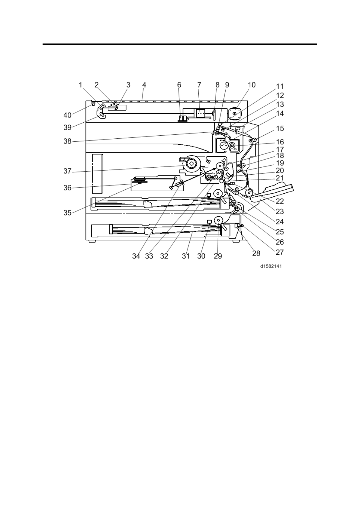
Component Layout
• D170: No duplex unit
• D158/D159: CCD scanner
• D160/D161/D170: C IS scan ner
Detailed Descriptions 1 D158/D159/D160/D161/D170

Component Layout
1. 2nd Mirror
2. Exposure Lamp
3. 1st Mirror
4. Exposure Glass
6.
7. Lens Block
8. SBU
9. Exit Sensor
10. Scanner Motor
11. Inverter Roller
12. Duplex Invert er Sensor
13. Duple
14 . H ot R oll er
15. Upper Transport Roller
16. Pressure Roller
17. OPC Drum
18 . Middl e Transpor t R oller
19. Duplex Exit Sensor
20. Image Density S ensor
21 . R egist rat ion Roll er
22 . R egist rat ion Sen sor
23. By
24 . L ower Trans port Ro
25. Upper Relay Roller
26 . R elay Sen sor
27 . L ower Relay Roller
28. Vertical Transport Sensor
29 . Paper Feed Roller
30. Paper End Sensor
31. Bottom Pla te
32. PCU
33 . D evelopment Rol ler
34. WTL
35. Polygon Mirror Motor
36. Laser Unit
37. Toner Supply Bo
38. Ex it Ro ller
39. 3rd Mirror
40. Scanner HP Sensor
APS sensor (Length)
D158/D159/D160/D161/D170 2 Detailed Descriptions
x Entrance Sensor
-pass Tray
ller
tt le H older
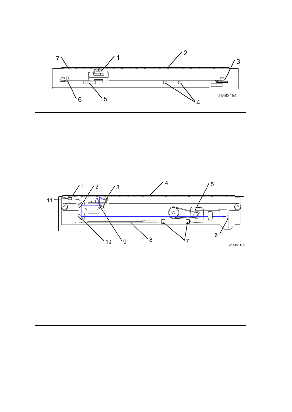
Component Layout
1.CIS Unit
2
3
4
5
6
7. DF
1. DF Exposure Glass
2.
3
4
5
6. SBU
7
8
9
10.3
11. Scanner HP Sensor
1.1.1 D160/D161/D170: CIS SCANNER COMPONENT LAYOUT
. APS Sensor (Width)
. Exposure Glass
. S canner HP Sen sor
. Scanner Motor
Exposure Glass
. APS Sensor (Length)
1.1.2 D158/D159: CCD SCANNER COMPONENT LAYOUT
2n d M irror
. Exposure Lamp
. Exposure Glass
. Scanner Motor
. APS Sensors
. Scanner Heater
. 1st Mirror
rd
Mirror
Detailed Descriptions 3 D158/D159/D160/D161/D170
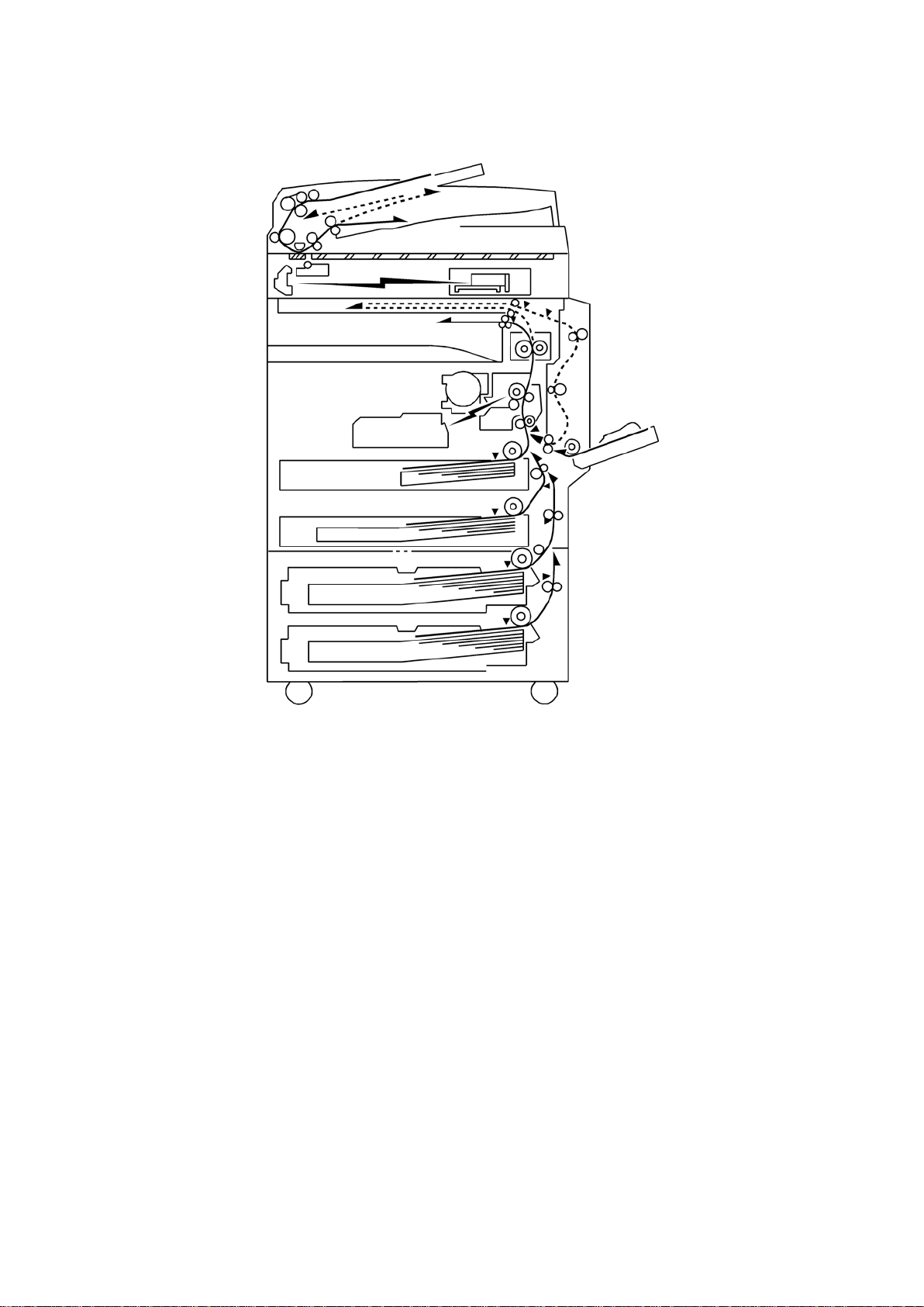
Paper Path
1.2 PAPER PATH
The D158, D159, D160, and D161 models have a duplex unit mounted on the right side of
the machine.
All models have a b y-p ass tr ay.
D158/D159/D160/D161/D170 4 Detailed Descriptions
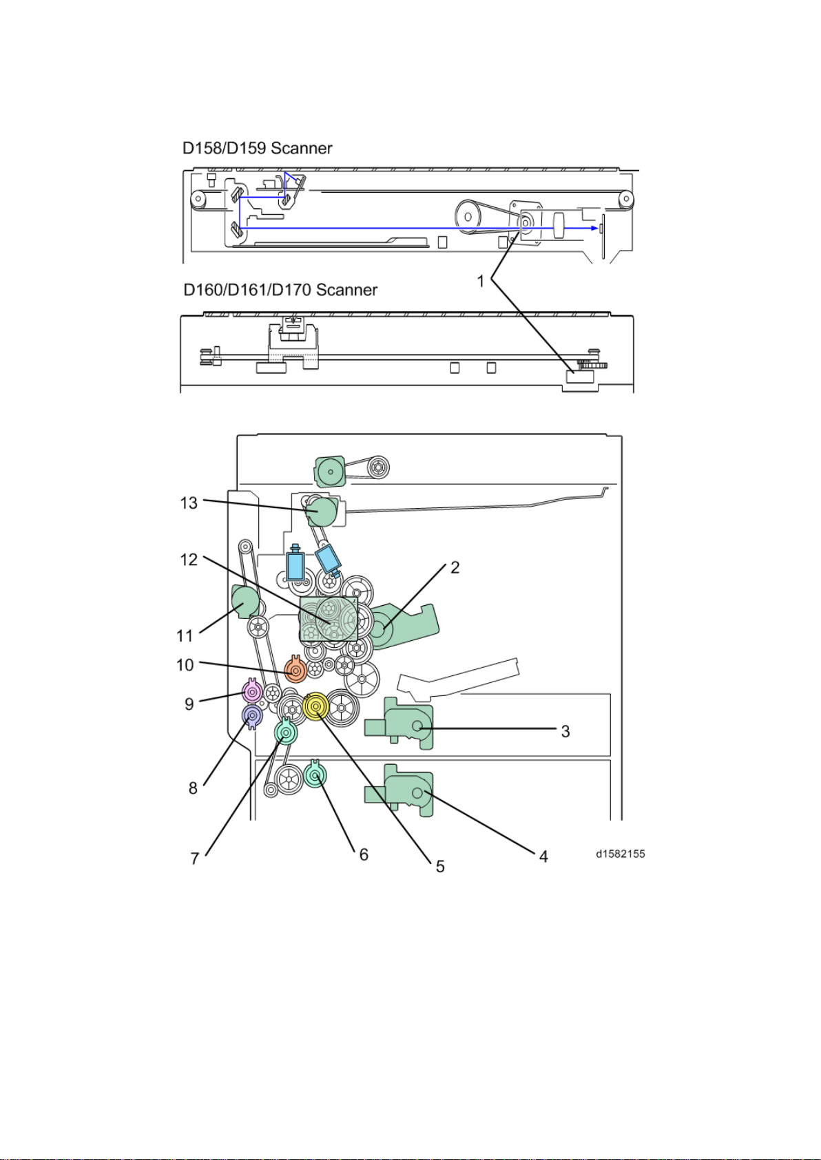
1.3 DRIVE LAYOUT
Dri ve L ayou t
Detailed Descriptions 5 D158/D159/D160/D161/D170

Dri ve L ayou t
1. Scanner Motor
8. By-pas s P aper Feed C lu tch
2. Toner Su pply M otor
3. Tray 1 Lift M otor
4. Tray 2Lift Motor
5. Upper Paper Feed Clutch
6. L ower Paper Feed Clutch
7. R elay Clut ch
9. By-pass Tray Lift Clutc h
10. Registration Clutch
11. Duplex Motor
12 . Main M otor
13. Inver ter Motor
D158/D159/D160/D161/D170 6 Detailed Descriptions
2. BOARD STRUCTURE
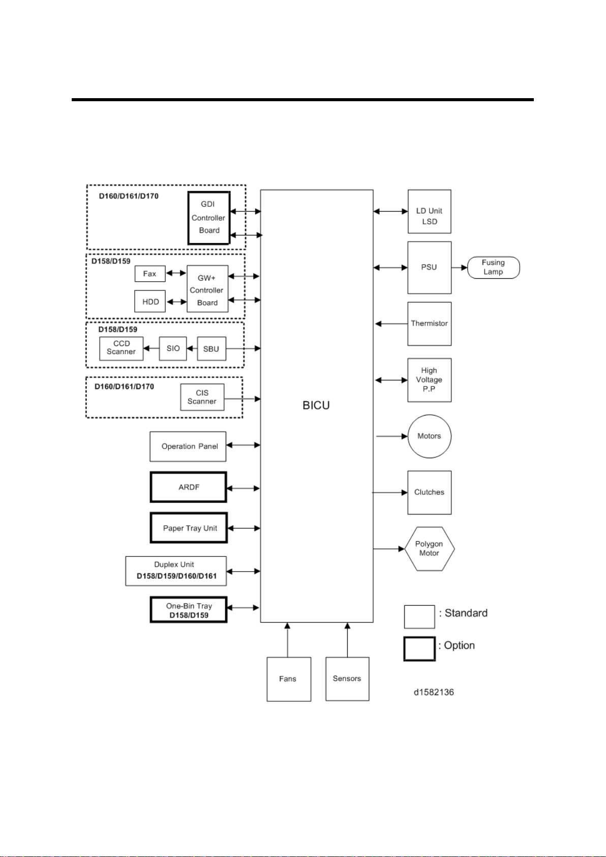
2.1 BLOCK DIAGRAM
Block Diagram
Detailed Descriptions 7 D158/D159/D160/D161/D170

SBU (Sensor Board Unit)
BICU (Base Engine and Image Control Unit)
The main board con tr ols the following functions:
Engine sequence
Timing control for peripherals
Im age processing, v ideo control
Operati on c ont rol, syst em contr ol ( Basic m achine only)
Mach in e con trol
Dri ve c ont rol for the sens ors, m otor s, and clutches of t he print er and scanner
High voltage supply board control
Serial in terfac es with p eripherals
Fusing control
2.2 SBU (SENSOR BOARD UNIT)
The SBU d eals wit h the an alog signals from the CCD and con verts th em int o digi tal signals.
The SBU is attached to the CCD scanner (D158/D159).
D158/D159/D160/D161/D170 8 Detailed Descriptions
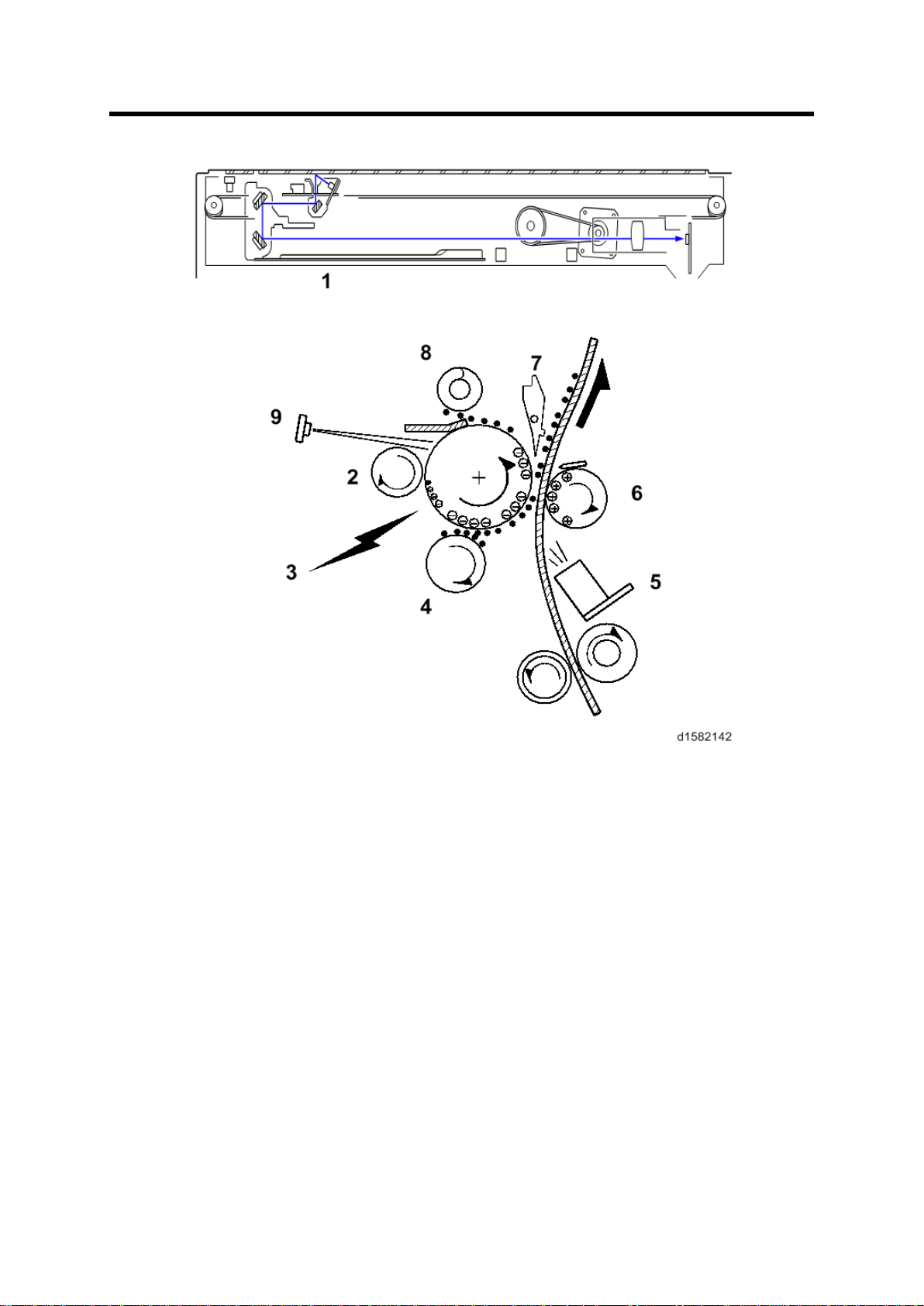
3. COPY PROCESS OVERVIEW
SBU (Sensor Board Unit)
1. Exposure
A xenon lamp exposes the origin al. Light reflec ted from the original passe s to th e CCD,
w here it is conver ted into an analog data signal. Thi s data i s c onver ted to a di gital signal,
processed and st ored in the memory. At the time of print in g, the dat a is ret rieved and
sent to the las er diode.
2. Drum Charge
In th e dark , the charge r oller gi ves a negati ve c harge to the organ ic phot o-conductive
(O PC ) drum. The c harge r emains on th e surface of the dru m because t he OP C layer has
a high elect rical resistance in th e dark .
3. Laser Exposure
The pr ocessed data scanned f rom th e origi nal is ret rieved from the memory and
trans ferred to the dru m b y a laser beam, which f orms an electrical latent image on th e
dr um surface. Th e amount of charge remainin g as a laten t image on th e drum depends
on the laser beam intensity, which is controlled by the BICU board.
Detailed Descriptions 9 D158/D159/D160/D161/D170

SBU (Sensor Board Unit)
4. Development
The magnet ic dev elop er brus h on th e development r oll er comes in c ontac t w ith the latent
image on th e drum sur fac e. Toner par tic les are el ectrostaticall y attached t o t he areas of
the drum surface wh ere th e laser red uced the negative charge on t he drum.
5. ID Sensor
The laser for ms a sensor pat ter n on t he drum surface. The ID sens or measures th e
reflectivity of the pattern. The output signal is one o f the factors used for toner sup pl y
cont rol . Al so, the ID sensor measures t he reflectivity of t he dr um surface. The outpu t
si gnal i s us ed f or char ge roll er v oltage con tr ol.
6. Image Transfer
Paper is fed to the area between the drum surface and the tran sfer roller at the proper
ti me for ali gning t he copy paper and the developed image on th e drum surface. T hen, the
trans fer r oller applies a high positive charge t o th e rever se s ide of t he paper. T his
positi ve charge pull s the ton er partic les f rom the drum surf ace ont o the p aper. At th e
same time, the paper is electr ostatically attracted to the tr ansfer rolle r.
7. Paper Separation
Paper separates f rom the drum as a r esult of t he elect ros tati c attraction between the
paper and t he t ransf er r oller. Th e disc harge pl ate ( groun ded) helps s eparate the pap er
from the drum.
8. Cleaning
The c leanin g blade removes any toner remai ni ng on t he drum su rface after t he imag e
trans fers to the paper.
9. Quenching
The light from the quenc hing l amp electrically neutr ali zes the c harge on the drum
surface.
D158/D159/D160/D161/D170 10 Detailed Descriptions
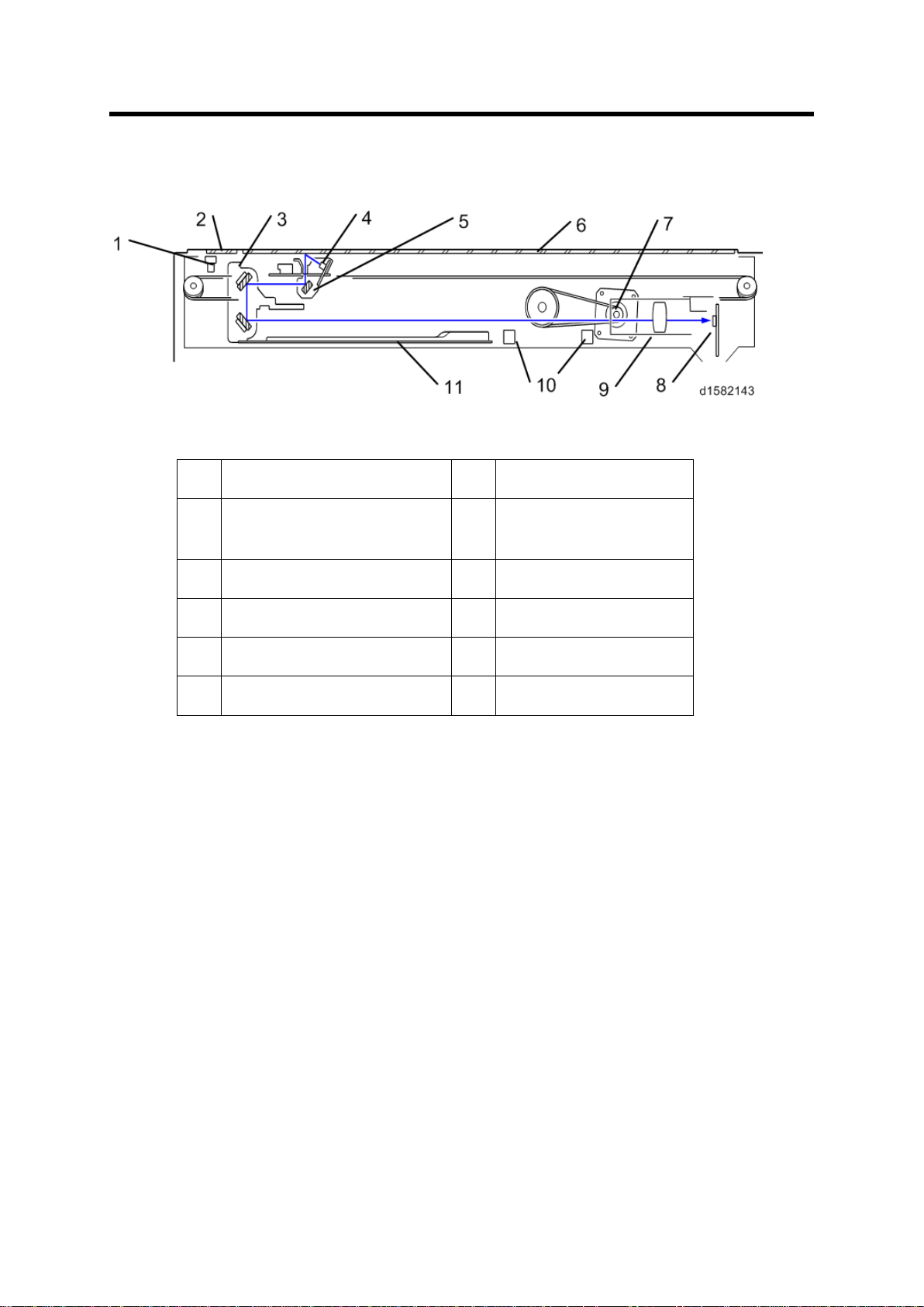
4. SCANNING D158/D159
1.
Scan ner HP s ensor
7.
Scan ner motor
2.
DF exposu re glass
8.
Sensor board unit
3.
2nd scanner (2nd carriage)
9.
Len s Block
4.
Scan ner lamp
10.
AP S s ensor
5.
1st s can ner (1s t carri age)
11.
Scanner Heater
6.
Exposure glass
4.1 OVERVIEW
Overview
(SBU)
The original on t he exp osure g la ss or ARDF exposure glass reflects the li ght emitted f rom
the scanner l amp. The reflected li ght goes t o th e CCD on the sensor b oard by way of the 1 st
and 2nd scanners. The sensor board converts th e CCD an alog sig nals into digital signals.
W hen the original is manually placed on the exposure glass, the scanner motor pulls the 1st
and 2nd scanners via mechanical linkage. The original is scanned from l eft to right.
Wh en th e origi nal is fed f rom th e optional A RDF, it is automat ical ly tr ansp orted ont o the
ARDF exposure glass, and to the original exit. The original does not stay on the glass; but
goes to the exit. T he 1st and 2nd scanners stay at their home positi ons.
Detailed Descriptions 11 D158/D159/D160/D161/D170
Scanner Drive
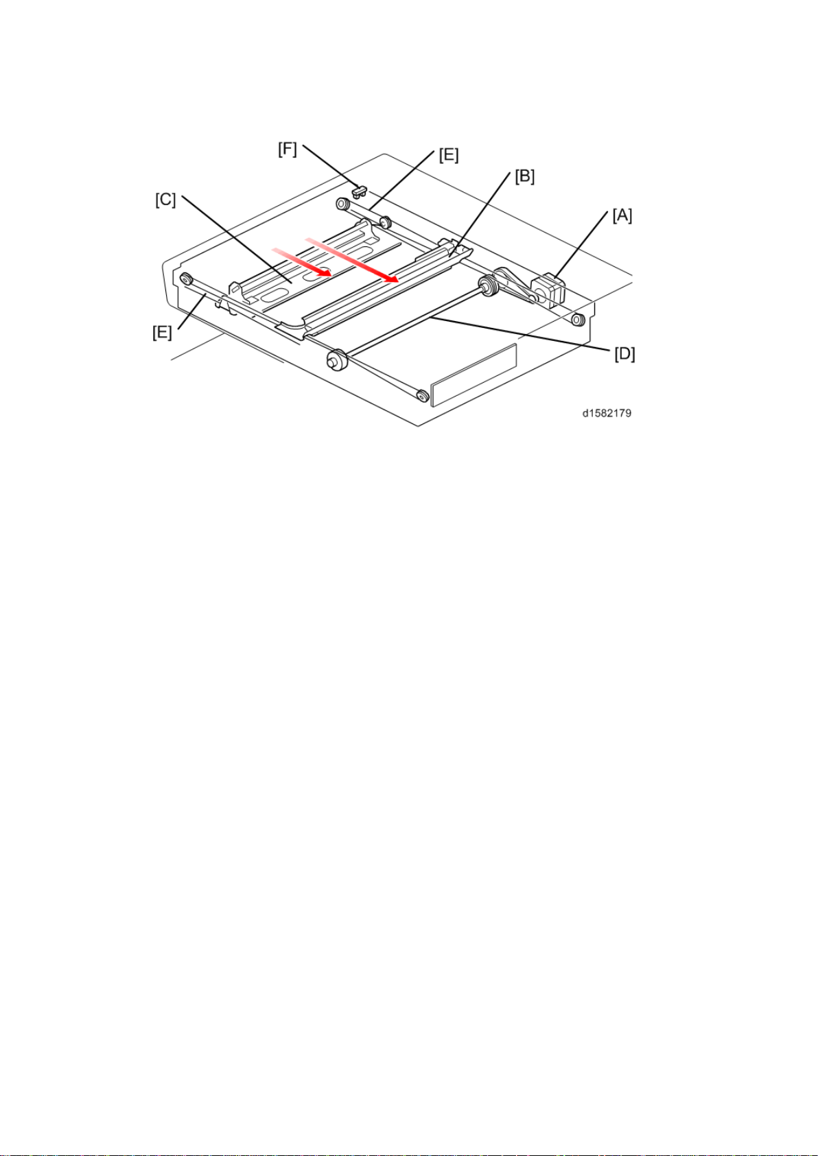
4.2 SCANNER DRIVE
The scanner mot or [A] drives the 1st scanner [B] and the 2nd scanner [C] through the
scanner drive pull ey, scan ner drive shaft [D], and t wo s canner wires [ E].
Book mode -
The SBU board controls the scanner drive motor. The 2nd scanner speed is half that of the
1st scanner.
In reduction or enlargement mode, the scan ni ng s peed depends on th e magnificat ion rat io.
The returning speed is always the same, whether in full size or magnification mode. The
image length change in the sub scan direction is done by changing the scanner m otor
speed. In the main scan direction it is done by im age processing on the BICU board.
You can adjust the magnification in the sub-scan direction by changing the scanner motor
speed with SP4-008.
ARDF mode -
The scanners always st ay in t heir home positi on (th e s canner HP sensor [F] detects the 1st
scanner ) t o sc an t he original. The AR DF motor f eeds th e ori gi nal t hrough t he A RDF. I n
reduction/enlargement mode, the image length change in the sub-scan direction is done by
changing the ARDF motor speed. Magnification in the main scan direction is done in the
BICU board. This is the same as for book mode.
You can adjust magnific ation in the sub-scan direction by changing the ARDF motor speed
with SP6 -017.
D158/D159/D160/D161/D170 12 Detailed Descriptions
Origi n al S iz e Detection in Pl at en M ode
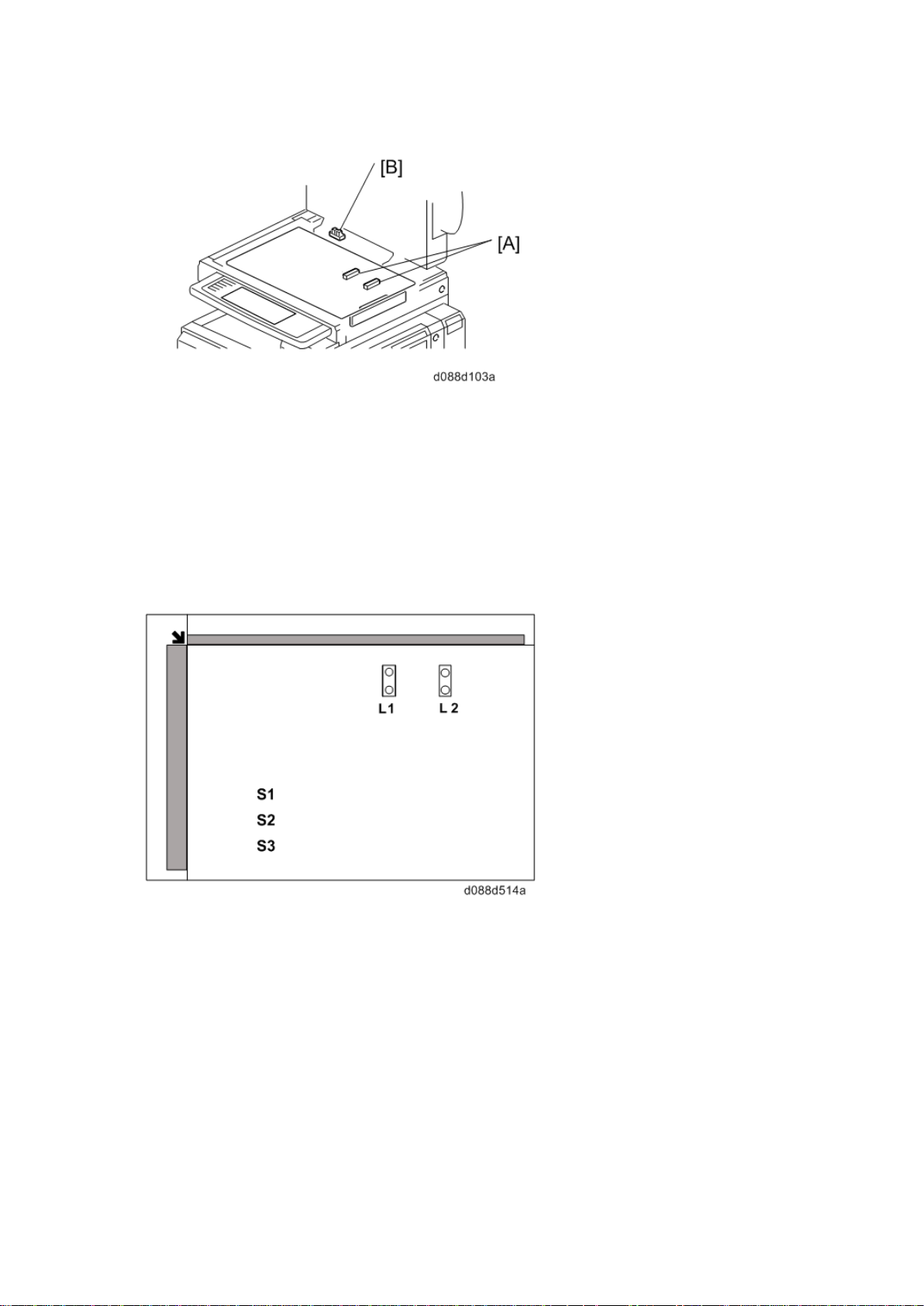
4.3 ORIGINAL SIZE DETECTION IN PLATEN MODE
Ther e are no APS s ensor ( width) in the scanner unit. However, the original width can be
detec ted by CCD . The A PS s ensor ( length) [A] det ects the original length.
The BIC U board ch eck s each s ensor status when the plat en c over s ensor [B] is
activated as it is closed. It det ects the or ig inal size by t he on/off s ignals it gets f rom each
sensor.
If the copy is mad e with t he platen cover f ul ly open, th e CPU det ermi nes the ori ginal size
from the sen sor outp ut s after t he S tar t key is pressed.
Detailed Descriptions 13 D158/D159/D160/D161/D170

Anti-Cond ensati on Heat er
4.4 ANTI-CONDENSATION HEATER
The anti-condensati on heater is av ailable as an optional unit. The anti-condensation heater
pr even ts con densat ion on th e mirror s. Cond ensation can occu r wh en the s canner unit is, for
example, moved from a col d room to a warm r oom. Condensati on c an c ause abno rmal
images.
D158/D159/D160/D161/D170 14 Detailed Descriptions

5. SCANNING D160/D161/D170
1. CIS unit (with carriage)
4. APS sensor (length)
2. Exposure Glass
5. APS sensor (widt h)
3. Scanner Motor
6. Scanner HP sensor
7. DF Exposure Glass
5.1 OVERVIEW
Overview
CIS unit
1-ch unity-magnifying contact im age sen sor (R GB_LED+SLA+C MOS
sensor)/capable of A3 color scanning
Bottom frame
Resin base
Upper frame
Composed of a resin base, exposure glass, and DF exposure glass
Sensor
1-ch CIS + integrated carriage + slide guide
Drive
Belt dr ive using a P M st epping motor
Exterior
The bottom fr ame (resin base) is integrated in to the exterior.
APS Sensor
2 width sensors and 2 length sensors (the sens or location depends on the country of
use)
Detailed Descriptions 15 D158/D159/D160/D161/D170
Scanner Drive
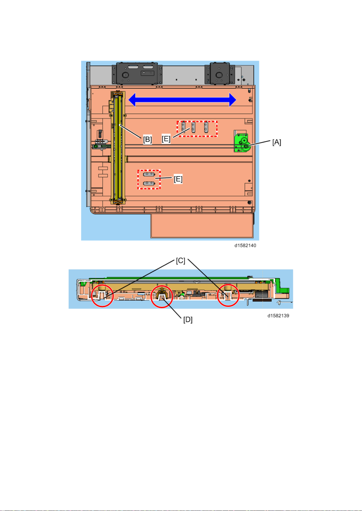
5.2 SCANNER DRIVE
Models D160, D161 and D170 are flat bed scanners using a CIS.
To s can an origi nal , the s canner motor (A ) moves the car riage on which the CIS (B ) is
mounted al ong th e car rier guide rail.
The CIS can be raised or lowered using the side guide rails (C) and adjusted relative to the
main scanning direction using the center guide rail (D). This is a factory adjustment; do not
do this in the field.
The size of th e original is detect ed by the AP S sen sor s (E) on t he bot tom fr ame.
D158/D159/D160/D161/D170 16 Detailed Descriptions

[A]: All areas except China
[B]: China only
Scanner Drive
Detailed Descriptions 17 D158/D159/D160/D161/D170
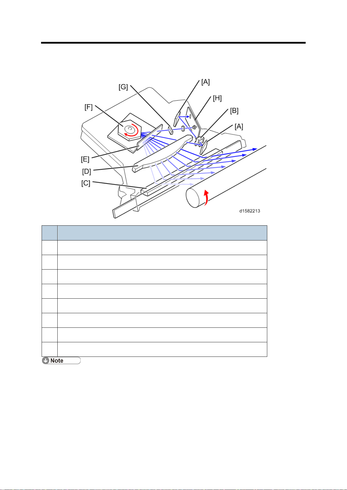
Overview
Name
A
Synchronization detect or mi rrors
B
Synchronization detect or lens
C
Mirror
D
F-thet a lens
E
Soundproof glass
F
Polygon Motor
G
Cylindrical lens
H
LD board
The LD drive board controls both the laser output and laser synchronization
mecha
The machine cuts off the power supply to the LD drive board if the front or right cover
is opened.
6. LASER EXPOSU RE
6.1 OVERVIEW
nism.
D158/D159/D160/D161/D170 18 Detailed Descriptions
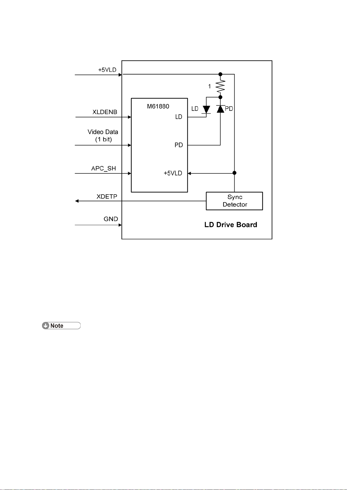
6.2 AUTO POWER CONT ROL (APC)
Do not touch the variable resistors on the LD unit in the field.
Auto Power Control (APC)
The LD driver IC drives the laser diode. To preven t the in ten sity of the laser b eam from
changing because of the temperature, the machine monitors the current passing through the
laser diode (LD). T he machine adjusts th e curr ent to the laser diode by compar in g i t with th e
re ference level from t he reference circuit.
This auto power c ont rol i s done jus t af ter th e machine i s turned on and during printing.
The laser diode power is adjus ted on the producti on lin e.
Detailed Descriptions 19 D158/D159/D160/D161/D170

LD Safety Switch
6.3 LD SAFETY SWITCH
To ensure t echnician and us er s afety and to prevent the laser beam from inad ver tently
switching on during servicing, safety switc hes are located at the front and right covers. The
switches are installed on the +5VLD line through the BICU board.
Wh en th e f ront cover or th e ri ght cover is opened, th e power s upply t o th e laser diode is
interrupted.
D158/D159/D160/D161/D170 20 Detailed Descriptions
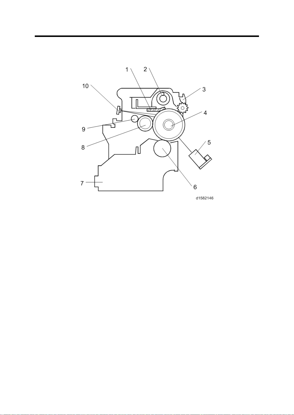
7. PHOTOCONDUCTOR UNIT (PCU)
1. Cleaning Blade
6. Dev elopment Rol ler
7.1 OVERVIEW
Overview
The PCU c onsists of th e components shown in t he above ill ustration. An organic
photoconductor (OPC) drum (diameter: 30 mm) is used in this machine.
2. Toner Collection Coil
3. Pick-of f Pawl
4. OPC Drum
5. ID Sensor (see note)
7. Dev elopment Unit
8. Charg e Roll er
9. Charge Roller Cleaning Brush
10. Quenching Lamp (see note)
Detailed Descriptions 21 D158/D159/D160/D161/D170
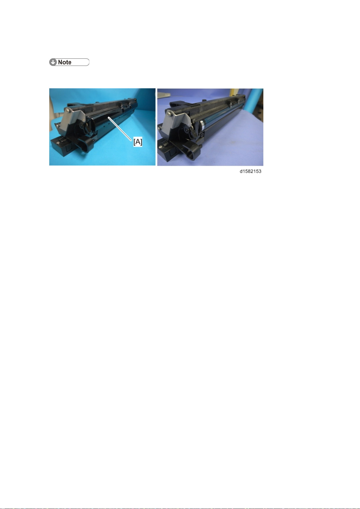
Overview
The ID sensor and quenching lamp are not included in the PCU.
The OPC drum's shutter [A] of
the previous model has been removed.
D158/D159/D160/D161/D170 22 Detailed Descriptions
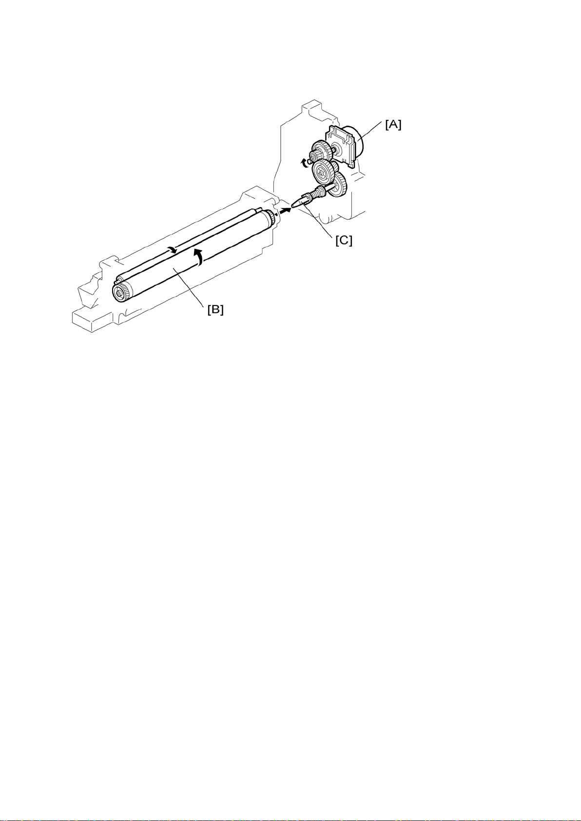
7.2 DRIVE
Drive
The main m otor [A] dr ives t he drum [B] through a s eries of ge ars and th e drum drive s haft
[C] . Th e mai n m otor ass embly inc lu des a d rive c ontr oller, which outputs a motor l ock s ig nal
w hen the rot ation sp eed is out of th e specified range.
Detailed Descriptions 23 D158/D159/D160/D161/D170
Overview
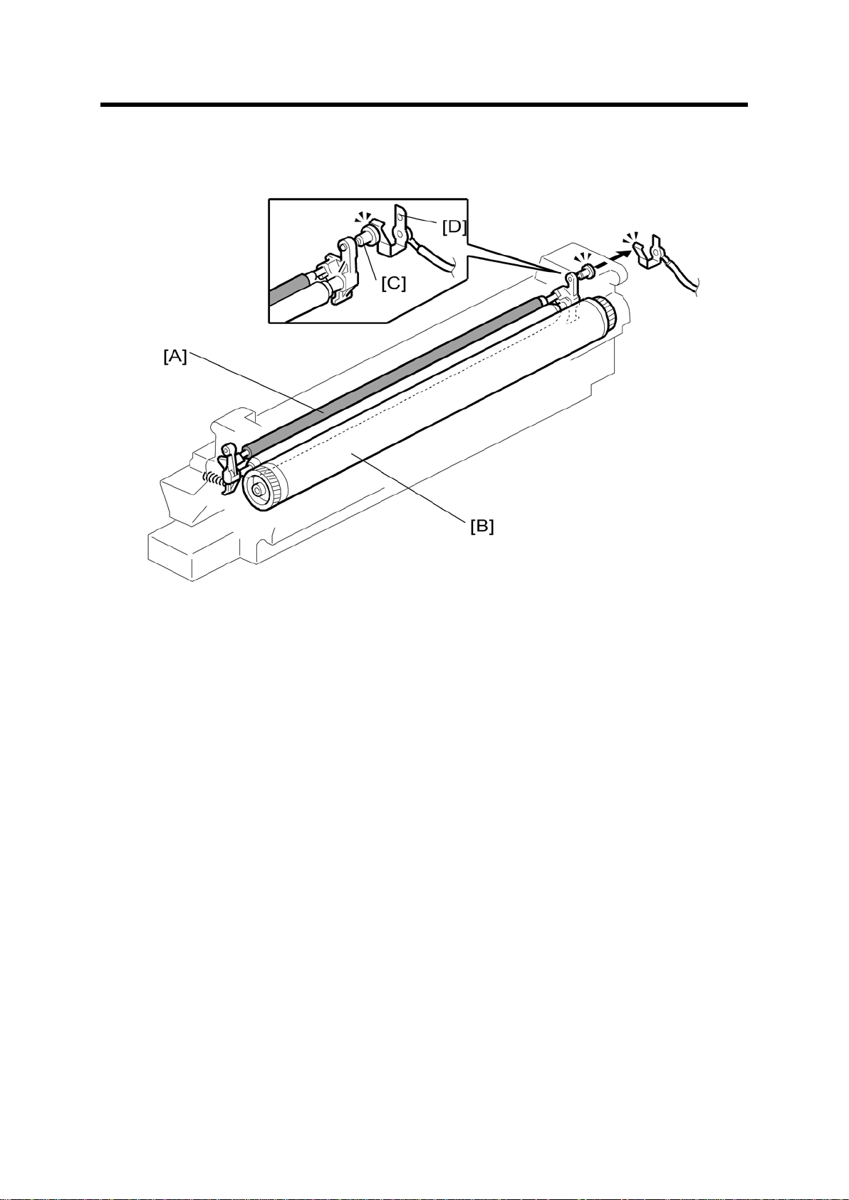
8. DRUM CHARGE
8.1 OVERVIEW
This cop ier uses a drum ch arge roll er t o charge the drum. The drum c harge roller [A] alway s
cont acts th e surface of th e drum [B ] to gi v e it a negat ive c harge of –950 V.
The high voltage supply board gives a negat ive c harge of –1700 V t o the drum charge roller
through the screw [C] and terminal plate [D]. This voltage can be changed using SP2-001001 (Charge Roll er Bias Adjust Setting (Copying)).
D158/D159/D160/D161/D170 24 Detailed Descriptions

ID Sensor Pattern Production Timing
8.2 ID SENSOR PATTERN PRODUCTION TIMING
The ID sen sor pattern is not made every page or every job.
It is only made in the following conditions:
During warm -u p at power on
W hen t he m ach in e st art s war ming up from energ y s aver mode and th e temper atu re
is less t han th e target temp erat ure as set w i th SP Mode.
When the machine start s war ming up from en ergy saver mode and t he machine
prints more than 100 prints after generating the p-pattern.
Detailed Descriptions 25 D158/D159/D160/D161/D170
 Loading...