

Ricoh D146, D147, D148, D149, D150 Service Manual
D146/D147/D148/D149/D150
SERVICE MANUAL


It is the reader's responsibility when discussing the information contained
within this document to maintain a level of confidentiality that is in the best
interest of Ricoh Americas Corporation and its member companies.
NO PART OF THIS DOCUMENT MAY BE REPRODUCED IN
ANY
FASHION AND DISTRIBUTED WITHOUT THE
PRIOR
PERMISSION OF RICOH AMERICAS
CORPORATION.
All product names, domain names or product illustrations, including
desktop images, used in this document are trademarks, registered
trademarks or the property of their respective companies.
They are used throughout this book in an informational or editorial fashion
only and for the benefit of such companies. No such use, or the use of
any trade name, or web site is intended to convey endorsement or other
affiliation with Ricoh products.
2013 RICOH Americas Corporation. All rights
reserved.

WARNING
The Service Manual contains information
regarding service techniques, procedures,
processes and spare parts of office equipment
distributed by Ricoh Americas Corporation.
Users of this manual should be either service
trained or certified by successfully completing a
Ricoh Technical Training Program.
Untrained and uncertified users utilizing
information contained in this service manual to
repair or modify Ricoh equipment risk personal
injury, damage to property or loss of warranty
protection.
Ricoh Americas Corporation
INSTALLATION
REVISION HIST OR Y
Pag e
Date
Add e d/ Upda ted/ Ne w
45 ~ 46
3/11/2014
Caster Table Type M3
81 ~ 82
12/23/2014
Internal shift tray
192 ∼ 197
10/08/2013
Added Smart Card Reader (D379) installation instructions.
198 ∼ 208
04/07/2014
Added Tray Heater sections
208
05/15/2014
Revised Step 12 of Paper Feed Unit PB3150
209 ~ 220
5/26/2015
Anti-Condensation Heater
Installation Requirements
SM
2-1
D146/D147/D148/D149/D150
Installation
2. INSTALLATION
2.1 INSTALLATION REQUIREMENTS
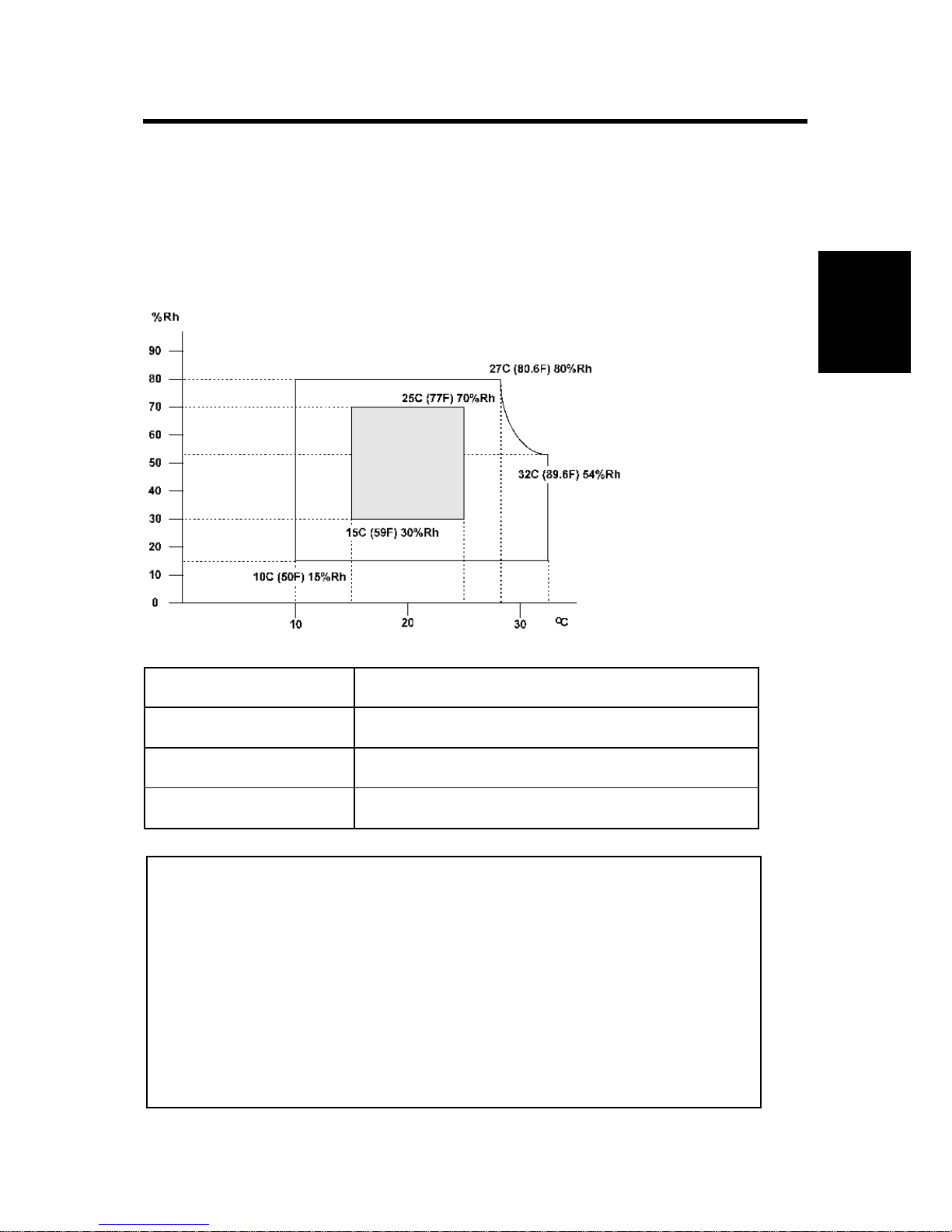
2.1.1 ENVIRONMENT
Temperature Range:
10°C to 32°C (50°F to 90°F)
Humidity Range:
15% to 80% RH
Ambient Illumination:
Less than 1,500 lux (do not expose to direct sunlight.)
Ventilation:
Room air should turn over at least 30 m3/hr/person
1. Avoid areas exposed to sudden temperature changes:
1) Areas directly exposed to cool air from an air conditioner.
2) Areas directly exposed to heat from a heater.
2. Do not place the machine where it will be exposed to corrosive gases.
3. Do not install the machine at any location over 2,000 m (6,500 ft.) above sea level.
(D135 for NA can be installed only up to 2,500m (8,202 ft.))
4. Place the main machine on a strong and level base. Inclination on any side should
be no more than 5 mm (0.2").
5. Do not place the machine where it may be subjected to strong vibrations.

Installation Requirements
D146/D147/D148/D149/D150
2-7
SM
2.1.2 MACHINE LEVEL
Front to back: Within 5 mm (0.2")
Right to left: Within 5 mm (0.2")
2.1.3 MACHINE SPACE REQUIREMENTS
[A]
Left Over 100 mm (3.9")
[B]
Rear
Over 100 mm (3.9")
[C]
Right
Over 100 mm (3.9")
[D]
Front
Over 750 mm (29.5")
Put the machine near the power source with the clearance shown above.

Installation Requirements
SM
2-3
D146/D147/D148/D149/D150
Installation
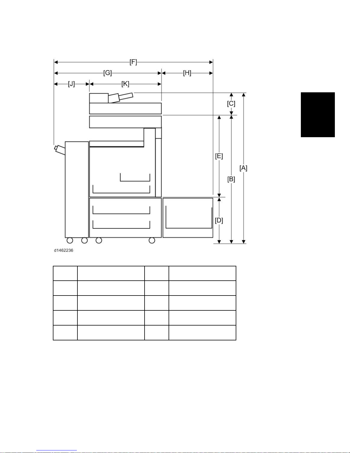
2.1.4 MACHINE DIMENSIONS
[A]
1210 mm
[F]
1589.5 mm
[B]
1030 mm
[G]
1249.5 mm
[C]
180 mm
[H]
340 mm
[D]
247 mm
[J]
662.5 mm
[E]
783 mm
[K]
587 mm
Installation Requirements
D146/D147/D148/D149/D150
2-4
SM
2.1.5 POWER REQUIREMENTS
·
Insert the plug firmly in the outlet.
·
Do not use an outlet extension plug or cord.
·
Ground the machine.
Input voltage level
Destination
Power supply
voltage
Rated current consumption
Permissible voltage
fluctuation
NA
120 to 127V
12A or more
Imaging: 108V(120V-10%)
to 138V(127V+8.66%)
Motions: 102V(120V-15%)
to 138V(127V+8.66%)
EU
220 to 240V
10A
Imaging: ±10%
Motions: ±15%
AP
CHN
SM
2-5
D146/D147/D148/D149/D150
Main Machine Installation
Installation
2.2 MAIN MACHINE INSTALLATION
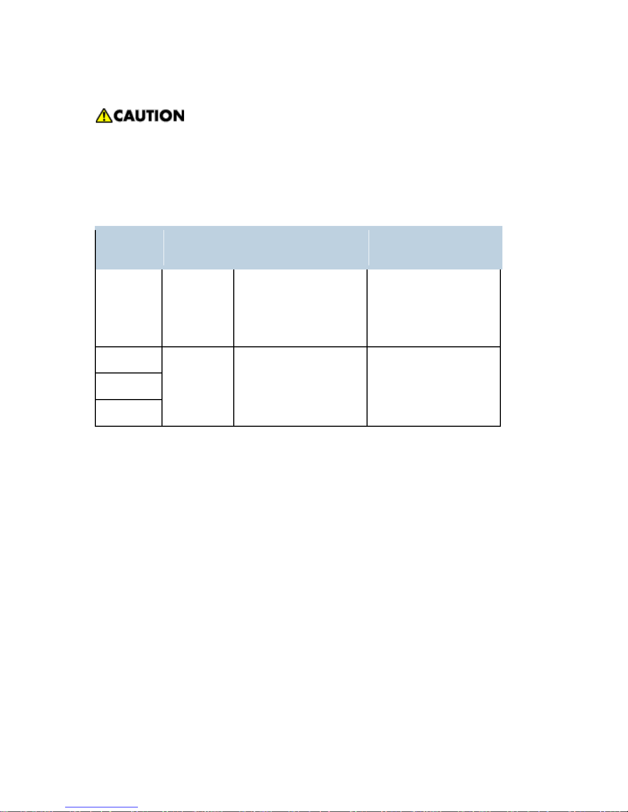
2.2.1 INSTALLATION FLOW CHART
You need the optional paper tray unit or the tandem LCT if you want to install the finisher D686,
D687, D688 or D689) or side LCT (D696).
The punch unit is for 1000-sheet booklet finisher (D686), 1000-sheet finisher (D687),
2000-sheet booklet finisher (D688) and 3000-sheet finisher (D689).

D146/D147/D148/D149/D150
2-6
SM
Main Machine Installation
2.2.2 ACCESSORY CHECK
Description
Q’ty
D146/D147
D148/ D149/ D150
Power Supply Cord (NA)
1
1
Operation Instructions
4
4
CD-ROM - Driver (NA)
1
-
CD-ROM - Driver
- 1
CD-ROM - OI
1
1
Sheet - 20 Languages (CHN)
1
1
Seal - 20 Languages
1
1
Holder 1 1
PCU Cover
4 4
Image Transfer Cover
1
1
Sheet - Application : Multi Language :Blank
1
1
Sheet - Application : Multi Language (NA)
1
1
Decal - Paper Tray
1
1
Decal - Original Table
1
1
Decal - Caution : Original : Multi Language
1
1
Plate – Logo
1 1
End Fence
1
1
SM
2-7
D146/D147/D148/D149/D150
Main Machine Installation
Installation
2.2.3 INSTALLATION PROCEDURE
·
Remove the tape from the development units before you turn the main switch on. The
development units can be severely damaged if you do not remove the tape.
Put the machine on the paper tray unit or the LCT first if you install an optional paper tray unit or
the optional LCT at the same time. Then install the machine and other options.
·
Keep the shipping retainers after you install the machine. You may need them in the
future if you transport the machine to another location.
Removal of packing materials and shipping retainers / Removal of PCDU
seal
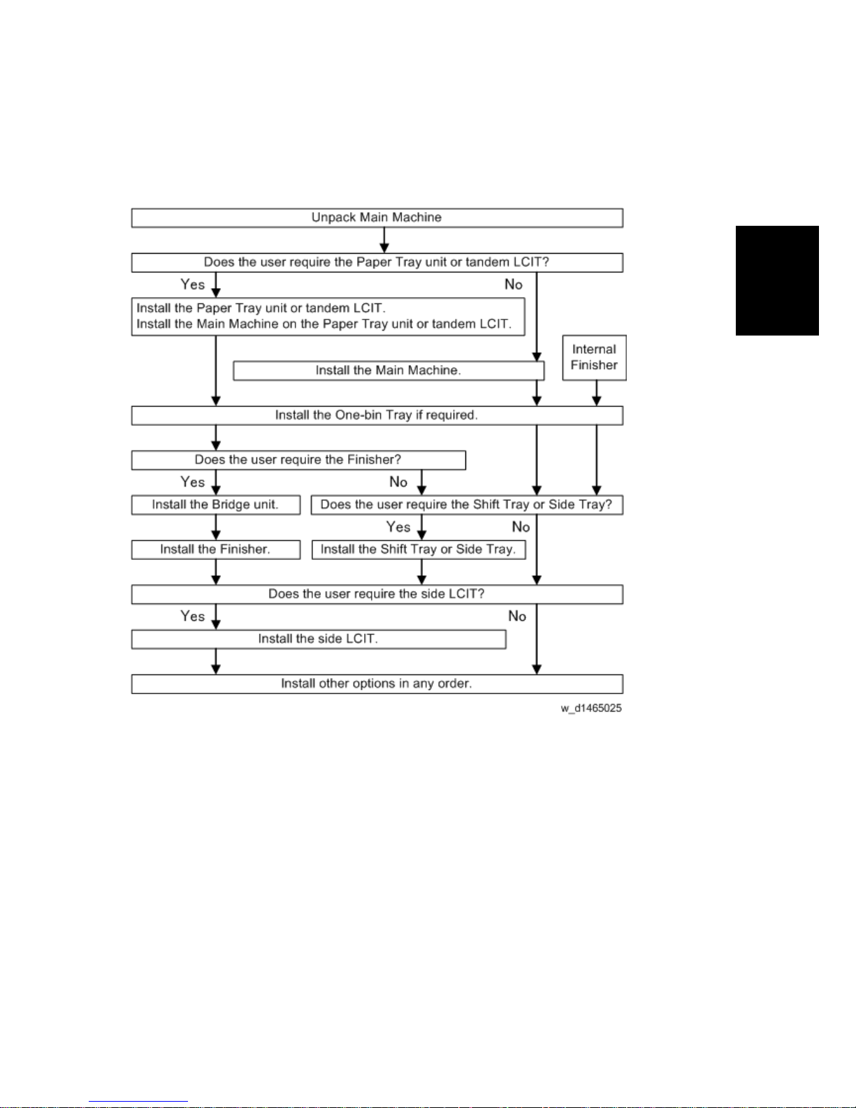
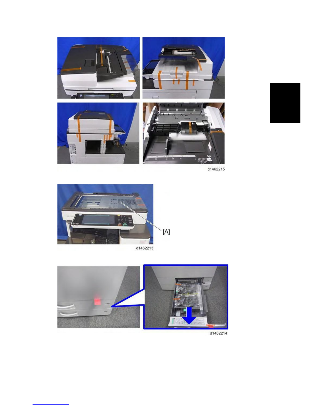
1. Remove the machine from the box, and check the items in the package.
·
Before lifting up the machine, as there are hidden handles, remove the retainers [A]
at the lower front right.
·
When you lift the machine, hold the correct parts, as shown in the diagram below.
·
Do not lift by holding the scanner unit, etc., because this might deform the machine
or break the exterior covers
D146/D147/D148/D149/D150
2-8
SM
Main Machine Installation
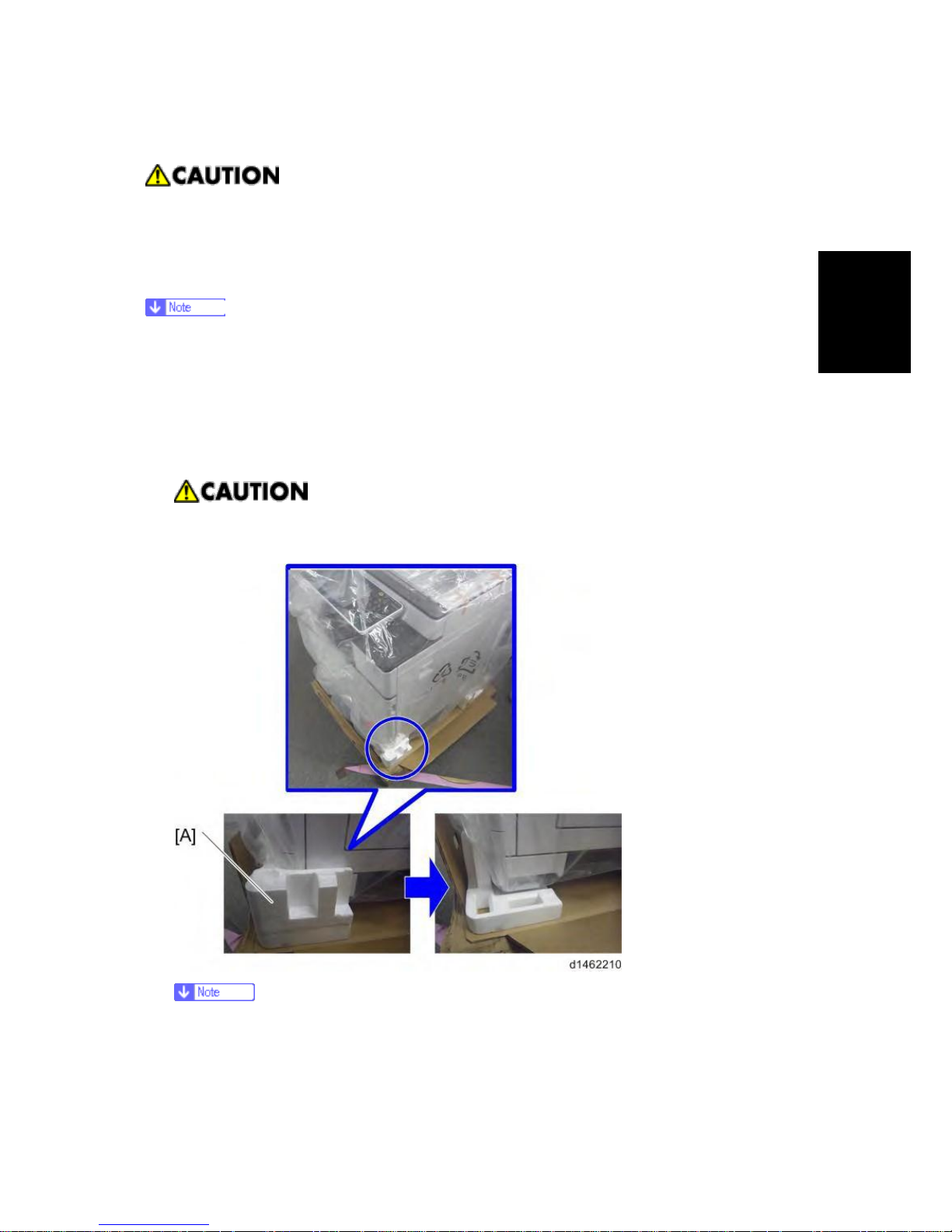
2. Remove the orange tape and retainers on the
outside.
For a machine with preinstalled SPDF,
remove the orange tape and retainers on the
SPDF.
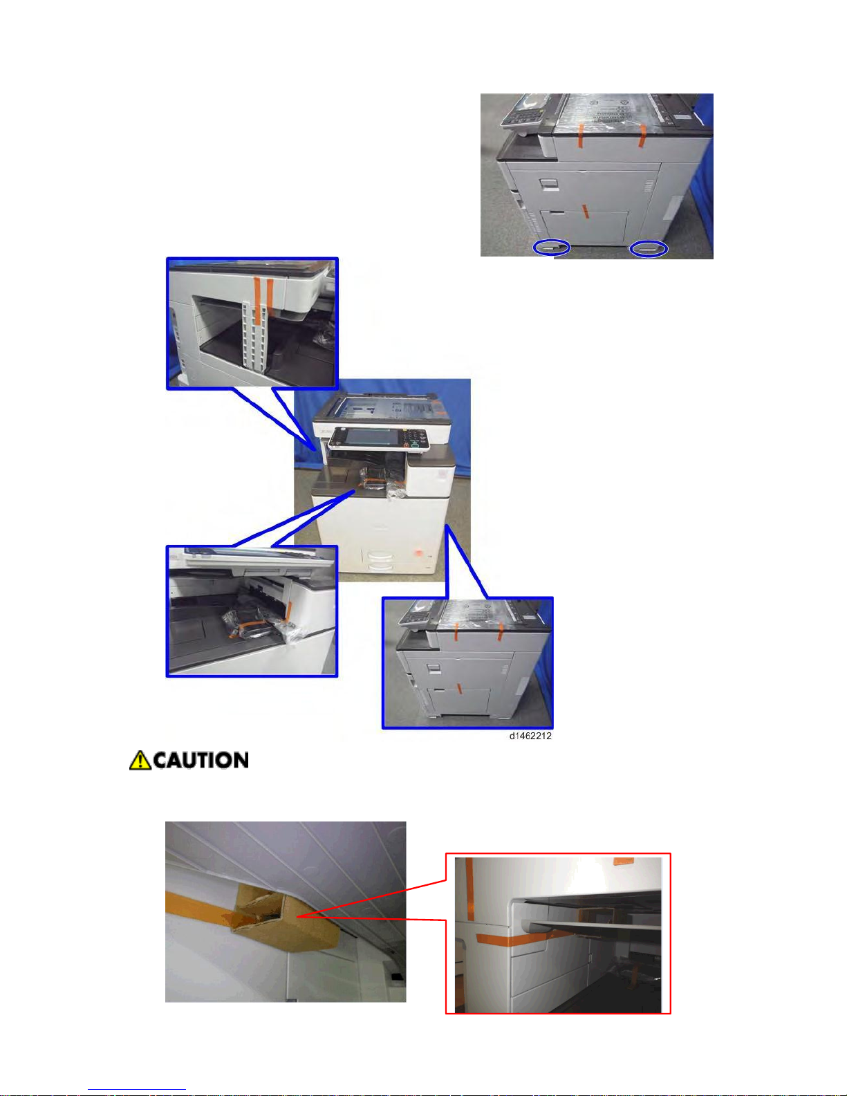
Make sure to remove the cardboard stabilizer shown below. If you do not, JAM 27 or JAM
64 may occur when printing out onto B4, DLT, or SRA3 sized paper in duplex mode.
SM
2-9
D146/D147/D148/D149/D150
Main Machine Installation
Installation
3. Remove the paper size decal [A] on the exposure glass.
4. Pull out the 1st paper feed tray, and remove the orange tape and retainers.
5. Pull out the 2nd paper feed tray, and remove the orange tape and retainers.
6. Remove the scanner support [A].

D146/D147/D148/D149/D150
2-
SM
Main Machine Installation
7. Open the front cover, and store the scanner support in the storage location [A].
·
The factory setting sheet is kept in the position [A].
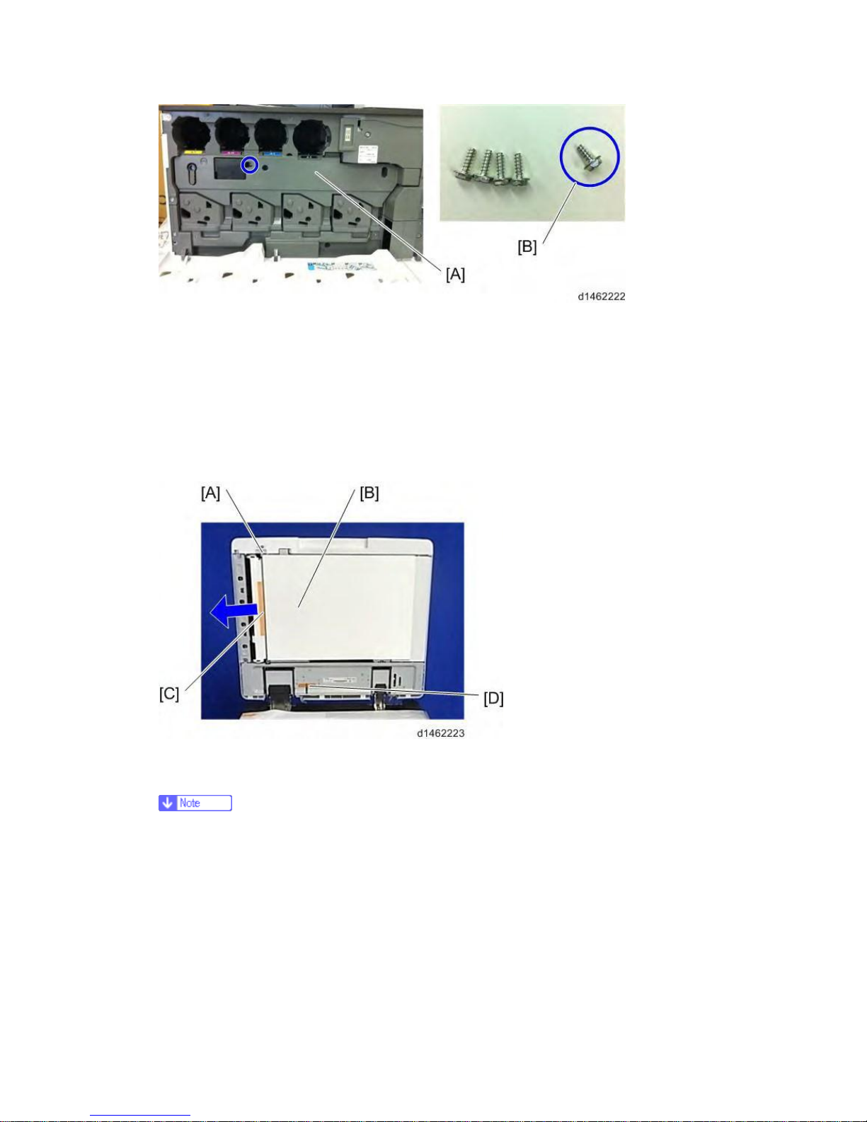
8. Remove the PCDU [A]. ( ×4, ×4)
SM
2-11
D146/D147/D148/D149/D150
Main Machine Installation
Installation
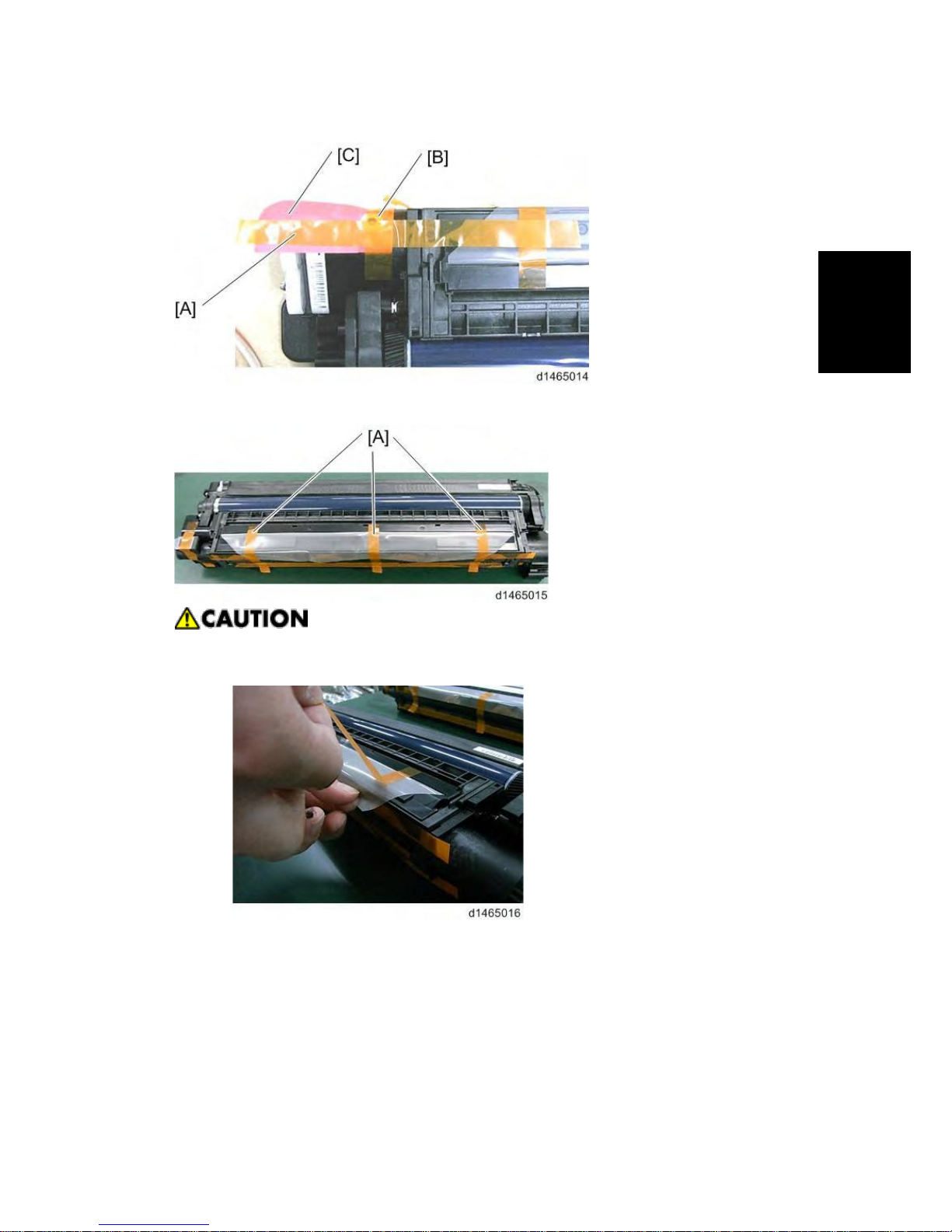
9. After removing the orange tape [A], remove the orange tape [B] and red tag [C].
10. Remove the orange tapes [A].
·
When removing the orange tapes, remove the orange tapes one by one without
removing the preset seal as shown below.
11. Remove the preset seal [A] in the direction of the blue arrow.
D146/D147/D148/D149/D150
2-
SM
Main Machine Installation
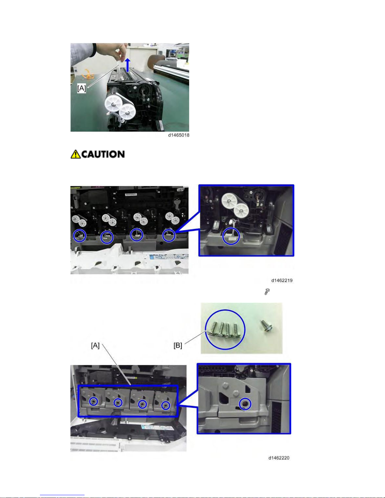
12. Return the PCDU to its original position, and connect the harnesses (4 for each unit).
·
When you return the PCDU to its original position, check the color (engraving), and
set each color unit in the right position.
13. Attach the PCDU front cover [A] with the screws provided (3×10) [B]. ( ×4)
SM
2-13
D146/D147/D148/D149/D150
Main Machine Installation
Installation
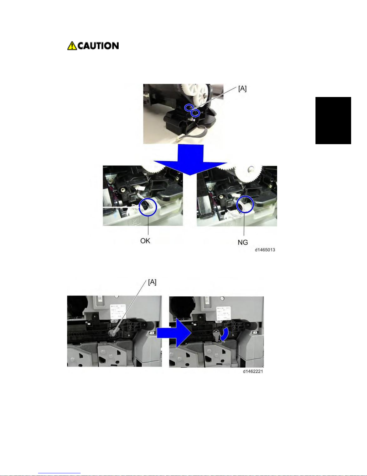
·
Be careful not to trap the harness with the PCDU front cover. Place the excess
portion of the harness on the inside of the inner cover. Also, hook the harness in two
places [A].
14. Rotate the ITB contact/separation lever [A] clockwise, and set it to the position in the following
picture.
15. Attach the ITB unit front cover [A] with the screw provided (3×8) [B].
D146/D147/D148/D149/D150
2-
SM
Main Machine Installation
16. Close the front cover.
For machines with preinstalled SPDF: Removal of protective sheet
1. Open the SPDF.
2. Release the lever [A], open the pressure plate sheet [B], and pull out the protective sheet [C]
slowly.
At this time, remove the filament tape [D].
3. Close the pressure plate sheet.
4. Close the SPDF.
·
If the protective sheet remains in the SPDF, a paper jam will be detected.
Toner bottle installation
1. Open the front cover.
2. Shake the toner bottle (Bk) 5 to 6 times.
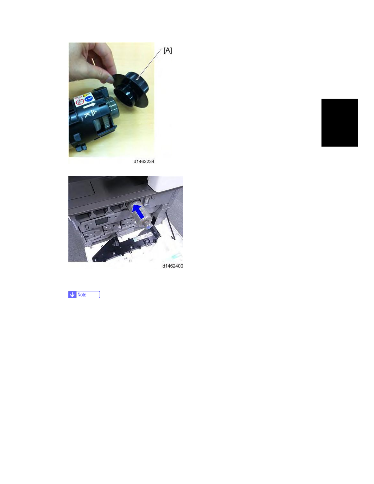
3. Remove the toner bottle protection cap [A].
SM
2-15
D146/D147/D148/D149/D150
Main Machine Installation
Installation
4. Push the toner bottle into the machine slowly.
5. Set the toner bottles (Y, M, C) in the same way.
6. Close the front cover.
·
When the power is turned on, it will fill up for the first time in about 5 minutes.
D146/D147/D148/D149/D150
2-
SM
Main Machine Installation
Attaching paper output tray parts
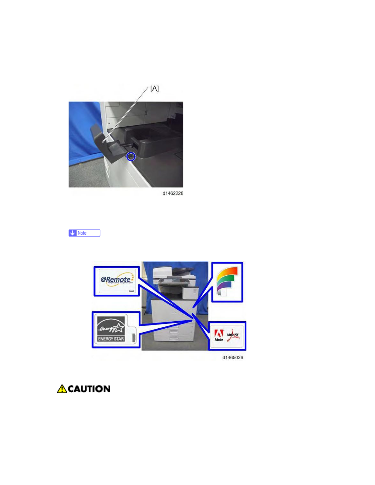
1. Attach the part [A] to the paper output tray.
First, insert and attach the front pin (inside the blue circle).
Attaching the decals
1. Attach the correct paper tray number and size decals to the paper trays.
·
Paper tray number and size decals are also used for the optional paper tray or the
optional LCT. Keep these decals for use with these optional units.
Connecting the power cord
·
Do not use any connectors other than the power cord provided. Also, do not use an
extension cord.
1. Connect the power cord to the machine.

SM
2-17
D146/D147/D148/D149/D150
Main Machine Installation
Installation
2.2.4 IMAGE QUALITY TEST / SETTINGS
Image quality test
When there are other options to be installed, install according to the procedure for each.
1. After checking that clamps, etc., have been removed, connect the power plug to the wall
socket.
2. Turn the main power supply switch ON.
3. Check that the operation panel shows the following display.
"Please supply the tray with paper."
4. The paper size is basically detected automatically.
1. Pull out the paper feed tray slowly until it stops.
2. While pressing the release lever, adjust the side fence to the paper size to be set.
3. Set the back fence.
Checking the copy image with the test chart
Check the copy image with the test chart.
Paper setting
1. Set some paper in the feed tray.
* SP5-181-001 to 017 (Size Adjust)
1. If necessary, adjust the registration for the paper feed tray.
* SP1-002-002 (Side-to-Side Registration Paper Tray 1)
* SP1-002-003 (Side-to-Side Registration Paper Tray 2)
Security Function Installation
The machine contains the Security functions (Data Overwrite Security and HDD Encryption unit)
built into the controller board.
If you are installing a new machine, it is recommended to activate the Data Overwrite Security and
HDD Encryption unit by selecting "Format All Data" from “System Settings” on the operation
panel.

D146/D147/D148/D149/D150
2-
SM
Main Machine Installation
·
This method is recommended because there is no user data on the hard drive yet
(Address Book data, image data, etc.).
If the customer wishes to activate the Data Overwrite Security and HDD Encryption unit on a
machine that is already running, it is recommended to activate the unit by selecting "All Data" from
“System Settings” on the operation panel.
·
Selecting "All Data" will preserve the data that has already been saved to the hard drive.
(If "Format All Data" is selected, all user data saved to the hard drive up to that point will
be erased).
Immediately after encryption is enabled, the encryption setting process will take several minutes
to complete before you can begin using the machine.
·
If encryption is enabled after data has been stored on the disk, or of the encryption key is
changed, this process can take up to three and a half hours or more.
The machine cannot be operated while data is being encrypted.
Once the encryption process begins, it cannot be stopped.
Make sure that the machine's main power is not turned off while the encryption process is in
progress.
If the machine's main power is turned off while the encryption process is in progress, the hard disk
will be damaged and all data on it will be unusable.
Print the encryption key and keep the encryption key (which is printed as a paper sheet).
Keep the encryption key in a safe place. If the encryption key is lost and is needed, the controller
board, hard disk and NVRAM must all be replaced at the same time.
·
"NVRAM" mentioned in he re means the NVRAM on the Controller Board.
·
"NVRAM" or EEPROM on the BCU has nothing to do with this.
Please use the following procedure when the Data Overwrite Security and HDD Encryption is
reinstalled.
Data Overwrite Security
Before You Begin the Procedure
1. Make sure that the following settings (1) to (3) are not at their factory default values.
(1) Supervisor login password
(2) Administrator login name
(3) Administrator login password
If any of these settings is at a factory default value, tell the customer these settings must be
changed before you do the installation procedure.
2. Make sure that “Admin. Authentication” is on.
[System Settings] -> [Administrator Tools] -> [Administrator Authentication Management] ->
SM
2-19
D146/D147/D148/D149/D150
Main Machine Installation
Installation
[Admin. Authen tication]
If this setting is off, tell the customer this setting must be on before you do the installation
procedure.
3. Make sure that “Administrator Tools” is enabled (selected).
[System Settings] -> [Administrator Tools] -> [Administrator Authentication Management] ->
[Available Settings]
If this setting is disabled (not selected), tell the customer this setting must be enabled
(selected) before you do the installation procedure.
Installation Procedure
1. Connect the network cable if it needs to be connected.
2. Turn on the main power switch.
3. Go into the SP mode and push “EXECUTE” in SP5-878-001.
4. Exit the SP mode and turn off the operation switch. Then turn off the main power switch.
5. Turn on the machine power.
6. Do SP5-990-005 (SP print mode Diagnostic Report).
7. Go into the User Tools mode, and select [System Settings] [Administrator Tools] [Auto
Erase Memory Setting] [On].
8. Exit the User Tools mode.
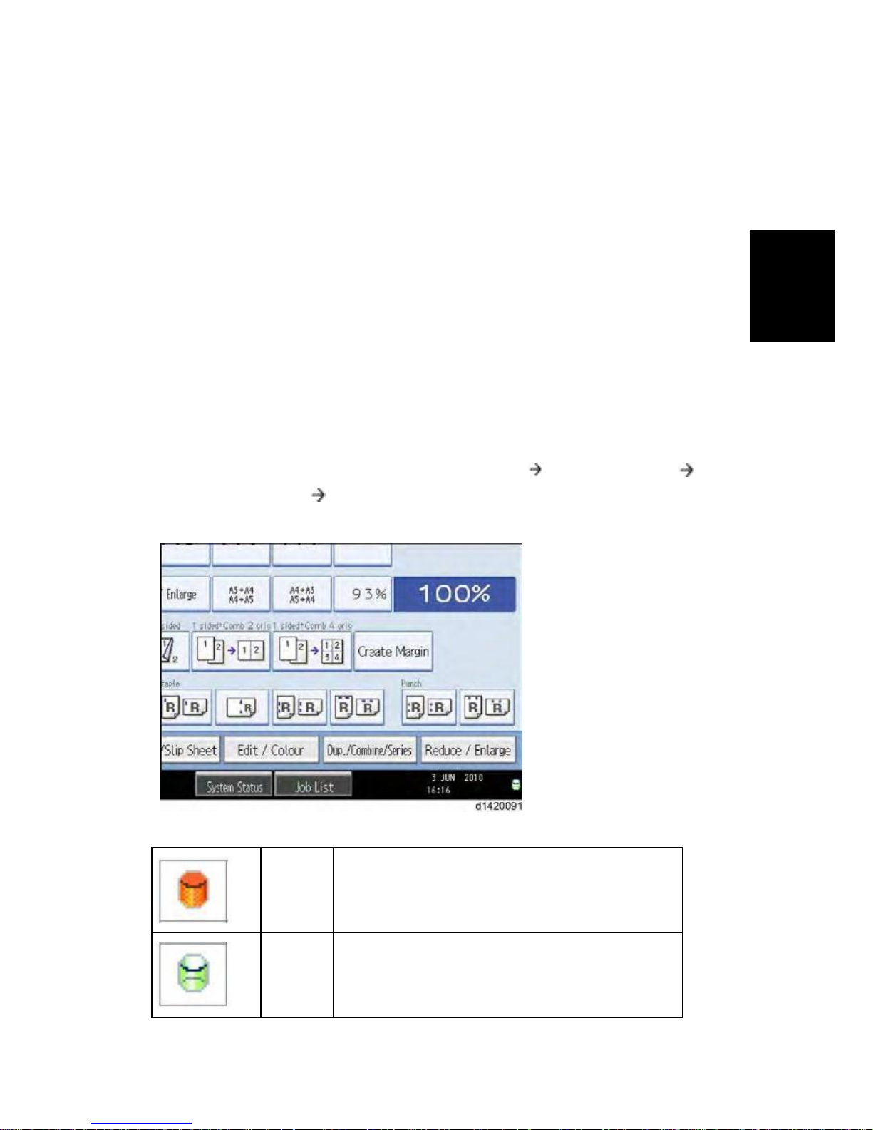
Icon [1]
This icon is lit when there is temporary data to be
overwritten, and blinks during overwriting.
Icon [2]
This icon is lit when there is no temporary data to be
overwritten.

D146/D147/D148/D149/D150
2-
SM
Main Machine Installation
9. Check the display and make sure that the overwrite erase icon appears.
10. Check the overwrite erase icon.
The icon [1] is lit when there is temporary data to be overwritten, and blinks during
overwriting.
The icon [2] is lit when there is no temporary data to be overwritten.
HDD Encryption
Before You Begin the Procedure:
1. Make sure that the following settings (1) to (3) are not at the factory default settings.
(1) Supervisor login password
(2) Administrator login name
(3) Administrator login password
These settings must be set up by the customer before the HDD Encryption unit can be
installed.
2. Confirm that "Admin. Authentication" is on: [User tools/Counter] key -> [System Settings] ->
[Administrator Tools] -> [Administrator Authentication Management] -> [Admin.
Authentication] -> [On]
If this setting is off, tell the customer that this setting must be on before you can do the
installation procedure.
3. Confirm that "Administrator Tools" is selected and enabled.
[User tools/Counter] key -> [System Settings] -> [Administrator Tools] -> [Administrator
Authentication Management] -> [Available Settings]
"Available Settings" is not displayed until step 2 is done.
If this setting is not selected, tell the customer that this setting must be selected before you
can do the installation procedure.
Installation Procedure:
1. Turn on the main power switch, and then enter the SP mode.
2. Select SP5878-002, and then press "Execute" on the LCD.
3. Exit the SP mode after "Completed" is displayed on the LCD.
4. Turn off the main power switch.
Enable Encryption Setting:
1. Press the [User tools/Counter] key.
2. Press [System Settings].
3. Press [Administrator Tools].
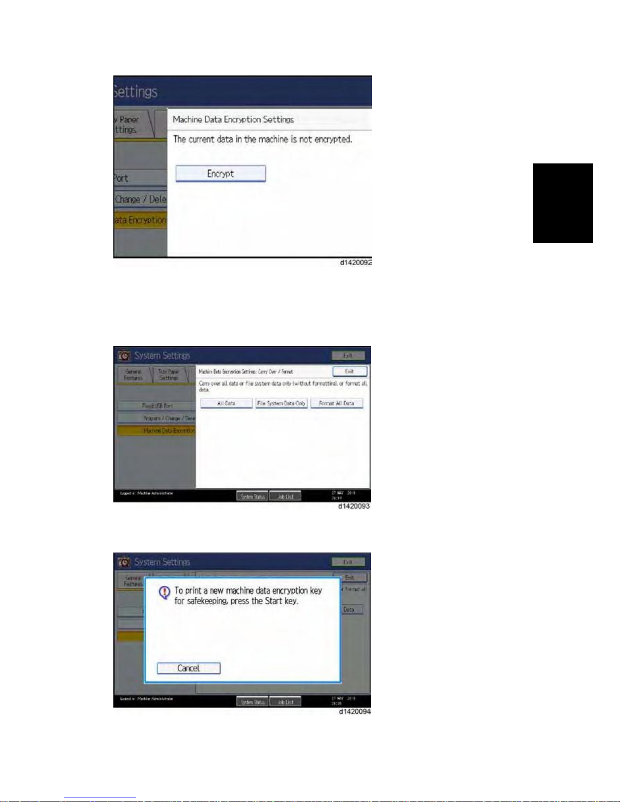
4. Press [Machine Data Encryption Settings].If this item is not visible, press [Next] to display
more settings.
5. Press [Encrypt].
SM
2-21
D146/D147/D148/D149/D150
Main Machine Installation
Installation
1. Select the data to be carried over to the hard disk and not be reset.
To carry all of the data over to the hard disk, select [All Data].
To carry over only the machine settings data, select [File System Data Only].
To reset all of the data, select [Format All Data].
2. The following message will be displayed. Press the [Start] key to print the encryption key for
safe keeping.
3. Press [Exit] to remove the following message.
D146/D147/D148/D149/D150
2-
SM
Main Machine Installation
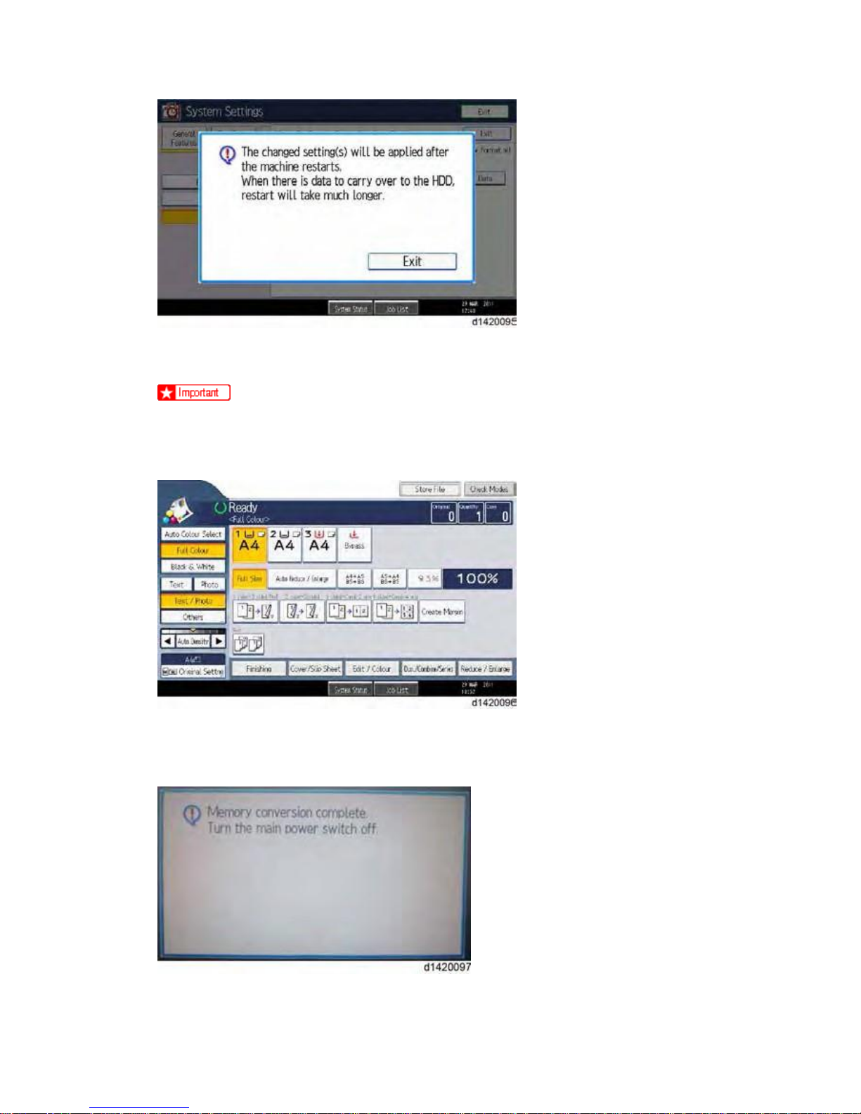
4. Press [Exit] again.
5. Press the [User Tools/Counter] key.
·
After step 10, the initial operation display appears as below. However, HDD data
encryption has not been completed at this moment. Step 11 and step 12 should be
performed in order to encrypt the HDD data.
6. Turn the main power switch off and on.
7. "Memory Conversion complete. Turn the main power switch off" is displayed as below. Then
turn the main power switch off and on.
8. Then initial operation display appears again. After this step, HDD data encryption has already
been completed.
SM
2-23
D146/D147/D148/D149/D150
Main Machine Installation
Installation
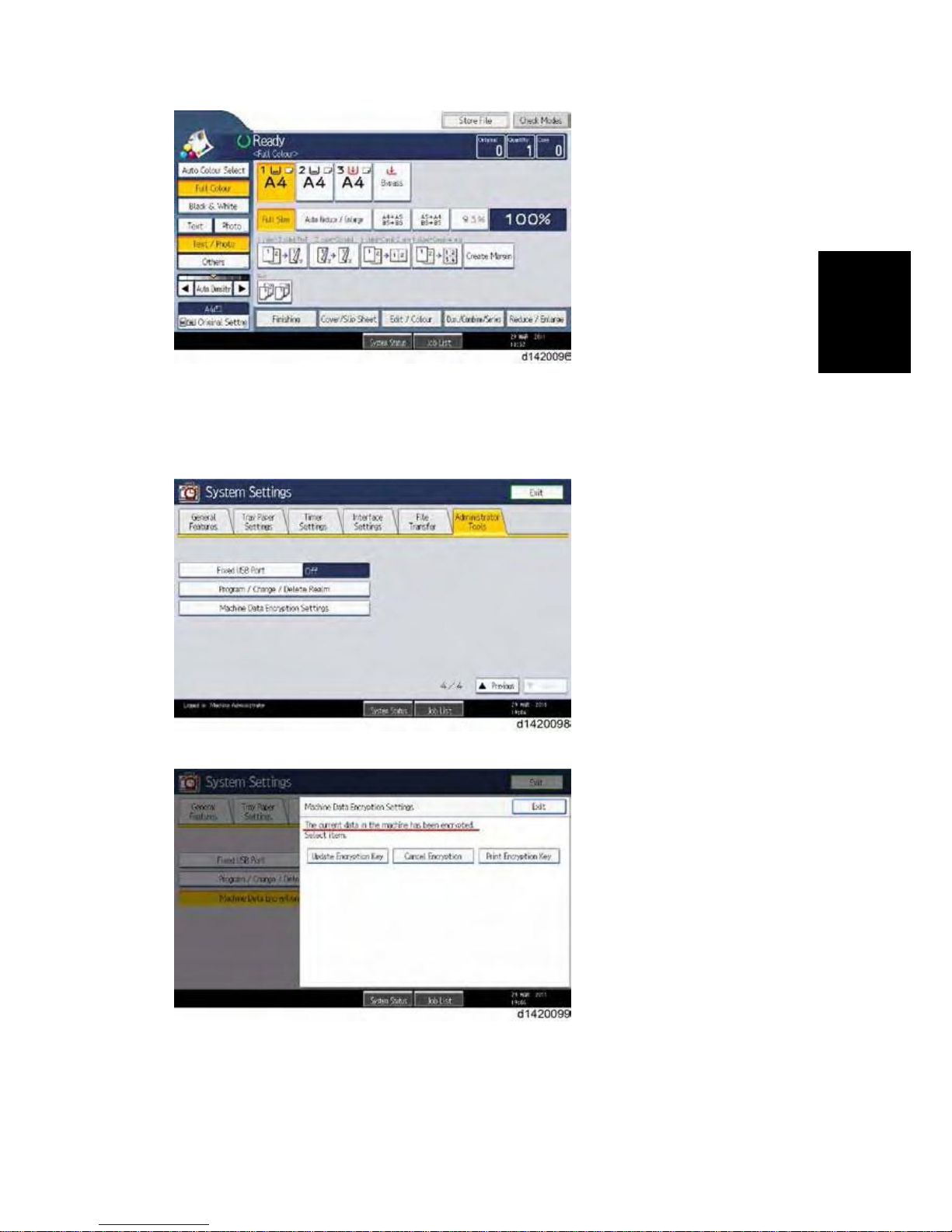
Check the Encryption Settings
1. Press the [User tools/Counter] key
2. Press [System Settings].
3. Press [Administrator Tools].
4. Press [Machine Data Encryption Settings].
5. Please confirm whether the encryption has been completed or not on this display.
D146/D147/D148/D149/D150
2-
SM
Main Machine Installation
Print the encryption key
Use the following procedure to print the key again if it has been lost or misplaced.
1. Press the [User tools/Counter] key.
2. Press [System Settings].
3. Press [Administrator Tools].
4. Press [Machine Data Encryption Settings].
If this item is not visible, press [Next] to display more settings.
1. Press [Print Encryption Key].
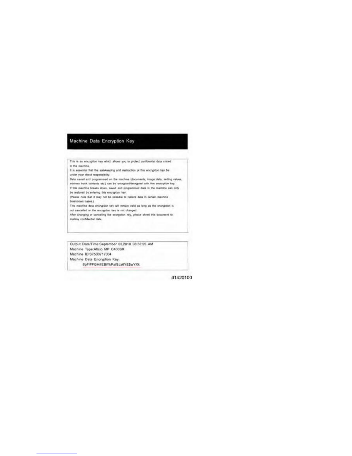
Encryption key sample
The encryption key is printed out as a sheet of paper like the example shown above.
Please instruct the customer to keep it in a safe place.
 Loading...