

Page 1

D127/D128
SERVICE MANUAL
Page 2

It is the reader' s resp onsibili ty when discuss ing th e info rmation c ontained
within this document to maintain a level of confidentiality that is in the best
interest of Ricoh Americas Corporation and its member companies.
NO PART OF THIS DOCUMENT MA Y BE REPRODUCED IN ANY
FASHION AND DISTRIBUTED WITHOUT THE PRIOR
PERMISSION OF RICOH AMERICAS CORPORATION.
All product names, domain names or product illustrations, including
desktop images, used in this document are trademarks, registered
trademarks or the property of their respective companies.
They are us ed thr ou ghout this b ook in an informa ti on al o r editorial fas hi o n
only and for the benefit of such companies. No such use, or the use of
any trad e name, or web si te is int ended to convey e ndorsement or other
affiliation with Ricoh products.
2012 RICOH Americas Corporation. All rights reserved.
Page 3

The Service Manual contains information
regarding service techniques, procedures,
processes and spare parts of office equipment
distributed by Ricoh Americas Corporation.
Users of this manual should be either service
trained or cer tified by successfull y completing a
Ricoh Technic al Trai ning Progr am .
Untrained and uncertified users utilizing
information contained in this service manual to
repair or modify Ricoh equipment risk personal
injury, damage to property or loss of warranty
protection.
Ricoh Americas Corporation
WARNING
Page 4

LEGEND
PRODUCT
CODE
COMPANY
LANIER RICOH SAVIN
D127 MP 301SP Aficio MP 301SP MP 301SP
D128 MP 301SPF Aficio MP 301SPF MP 301SPF
DOCUMENTATION HI S TORY
REV. NO.
DATE
COMMENTS
*
06/2012
Original Printing
Page 5

SM i D127/D128
D127/D128
TABLE OF CONTENTS
1. PRODUCT INFORMATION ........................................................... 1-1
1.1 SPECIFICATIONS ..................................................................................... 1-1
1.2 MACHINE CONFIGURATION ................................................................... 1-2
1.2.1 MAINFRAME .................................................................................... 1-2
1.2.2 SYSTEM COMPONENTS ................................................................ 1-3
1.3 OVERVIEW ................................................................................................ 1-4
1.3.1 CO MPONENT LAYOUT ................................................................... 1-4
Mainframe ............................................................................................ 1-4
ARDF ................................................................................................... 1-5
1.3.2 ELECTRICAL COMPONENTS ......................................................... 1-6
Electrical Components 1 ...................................................................... 1-6
Electrical Components 2 ...................................................................... 1-7
ARDF ................................................................................................... 1-8
1.3.3 PAPER PAT H ................................................................................... 1-9
1.3.4 DRIVE LAYOUT ............................................................................. 1-10
Mainframe .......................................................................................... 1-10
ARDF ................................................................................................. 1-11
1.4 G UIDANCE FOR THOSE WHO ARE FAMILIAR WITH PREDECESSOR
PRODUCTS ................................................................................................... 1-12
2. INSTALLATION ............................................................................. 2-1
2.1 INSTALLATION CAUTIONS ...................................................................... 2-1
2.2 I NSTALLATION REQUIREMENTS ............................................................ 2-2
2.2.1 ENVIRONMENT ............................................................................... 2-2
2.2.2 MACHI NE LEVEL ............................................................................. 2-2
2.2.3 MINIMUM OPERATIONAL SPACE REQUIREMENTS .................... 2-3
2.2.4 POWER REQUI REMENTS .............................................................. 2-4
2.3 COPIER ..................................................................................................... 2-5
2.3.1 ACCESSORY CHECK ...................................................................... 2-5
Printer/Scanner (D127)/ Scanner and Fax Model (D128) ..................... 2-5
Installation Procedure........................................................................... 2-6
Interface settings .................................................................................. 2-9
Page 6

D127/D128 ii SM
Copier settings ..................................................................................... 2-9
Fax Settings ....................................................................................... 2-10
2.3.2 OPTIONAL HANDSET.................................................................... 2-10
Accessory Check................................................................................ 2-10
Installation Procedure......................................................................... 2-11
2.4 PAPER TRAY UNIT (D661) ..................................................................... 2-12
2.4.1 ACCESSORY CHECK .................................................................... 2-12
2.4.2 IN STALLATION PROCEDURE ...................................................... 2-12
2.5 PAPER TRAY UNIT HEATER ................................................................. 2-15
2.5.1 ACCESSORY CHECK .................................................................... 2-15
2.5.2 IN STALLATION PROCEDURE (FOR ONE OF PT U INSTALLED
MACHINE) ............................................................................................... 2-17
2.5.3 IN STALLATION PROCEDURE (FOR TWO OF PTU INSTALLED
MACHINE) ............................................................................................... 2-21
2.5.4 JOINT BRACKET ( JOINT THE COPIER AND THE UPPER PT U) . 2-27
2.5.5 JOINT BRACKET ( JOINT THE U PPER AND THE LOWER PTU) . 2-28
2.6 CO NTROLLER OPTIONS ....................................................................... 2-29
2.6.1 OVERVIEW .................................................................................... 2-29
2.6.2 WIRELESS LAN (IEEE 802.11A/G) INSTALLATION ..................... 2-30
Accessories ........................................................................................ 2-30
Installation Procedure......................................................................... 2-30
SP Mode Settings for IEEE 802.11a/g Wireless LAN ......................... 2-31
2.6.3 IEEE 1284 INSTALLATION ............................................................ 2-31
Accessories ........................................................................................ 2-31
Installation Procedure......................................................................... 2-32
2.6.4 VM CARD TYPE S (D65 6) .............................................................. 2-33
Accessories ........................................................................................ 2-33
Installation .......................................................................................... 2-33
2.6.5 GIGABIT ETHERNET ..................................................................... 2-34
2.6.6 FAX OPTION (D655) ...................................................................... 2-35
Component Check.............................................................................. 2-35
Installation Procedure......................................................................... 2-36
Grounding Wire .................................................................................. 2-37
2.6.7 HDD OPTI ON (D659) ..................................................................... 2-38
Component Check.............................................................................. 2-38
Installation Procedure......................................................................... 2-39
Installing the Security Card ................................................................ 2-40
Activating the Security Applications.................................................... 2-41
Page 7

SM iii D127/D128
HDD Encryption Recovery from a Device Problem ............................ 2-41
Restoring the Encryption key ............................................................. 2-42
Clearing the NVRAM .......................................................................... 2-43
3. PREVENTIVE MAINTENANCE..................................................... 3-1
3.1 MAI NTENANCE TABLES .......................................................................... 3-1
3.2 HOW TO CLEAR THE PM COUNTER ...................................................... 3-2
4. REPLACEMENT AND ADJUSTMENT ......................................... 4-1
4.1 PRECAUTIONS ......................................................................................... 4-1
4.1.1 GENERAL ......................................................................................... 4-1
4.1.2 LITHIUM BATTER IES....................................................................... 4-1
4.1.3 HALOGEN-FREE CABLE ................................................................. 4-1
4.1.4 STATIC ELECTRICITY ..................................................................... 4-1
4.2 SPECIAL TOOLS AN D LUBRICANTS ...................................................... 4-2
4.3 EXTERIOR COVERS AND OPERATION PANEL ..................................... 4-3
4.3.1 REAR COVER .................................................................................. 4-3
4.3.2 CO PY TRAY ..................................................................................... 4-3
4.3.3 OPER ATION PANEL ........................................................................ 4-4
4.3.4 RIGHT DOOR ................................................................................... 4-5
4.3.5 BYPASS TRAY ................................................................................. 4-5
4.3.6 PLATEN COVER AND AR DF SENSOR ........................................... 4-6
4.4 SCANNER UNIT ........................................................................................ 4-7
4.4.1 SCANNER COVER AND EXPOSURE GLASS ................................ 4-7
4.4.2 LED UNIT ......................................................................................... 4-8
4.4.3 SCANNER MOTOR .......................................................................... 4-9
4.4.4 SCANNER HP SENSOR .................................................................. 4-9
4.5 FUSING ................................................................................................... 4-10
4.5.1 FUSING UNIT ................................................................................. 4-10
4.5.2 EXIT SENSOR ................................................................................ 4-10
4.5.3 HO T ROLLER ST RIPPER PAWLS................................................. 4-11
4.5.4 HOT ROLLER AND FUSING LAMP ............................................... 4-12
4.5.5 THERMOSWITCHES AND THERMISTOR .................................... 4-13
4.5.6 PRESSURE ROLLER ..................................................................... 4-14
4.5.7 FUSING NIP BAND CHECK BY-PASS (CHECKING THE NIP BAND)
4-15
4.6 PCU AND QUENCHING LAMP ............................................................... 4-16
4.6.1 PCU ................................................................................................ 4-16
4.6.2 QUENCHING L AMP ....................................................................... 4-17
Page 8

D127/D128 iv SM
4.7 EXHAUST FAN AND MAIN MOTOR ....................................................... 4-18
4.7.1 EXHAUST FAN ............................................................................... 4-18
4.7.2 MAIN MOTOR ................................................................................ 4-19
4.8 PAPER FEED .......................................................................................... 4-21
4.8.1 PAPER FEED ROLLER AND FRICTION PAD ............................... 4-21
4.8.2 PAPER END SENSOR ................................................................... 4-22
4.8.3 REG ISTRATION SEN SOR ............................................................. 4-23
4.8.4 BYPASS PAPER END SENSOR .................................................... 4-24
4.8.5 BYPASS FEED ROLLER ................................................................ 4-25
4.8.6 BYPASS FEED CLUTCH AND FRICTION PAD ............................. 4-26
4.8.7 PAPER FEED AND REGISTRATION CLUTCHES ........................ 4-27
4.9 IMAGE TRANSFER ................................................................................. 4-28
4.9.1 TRANSFER ROLLER ..................................................................... 4-28
4.9.2 ID SENSOR AND DUPLEX ROLLER ............................................. 4-29
4.9.3 DI SCHARGE PLATE ...................................................................... 4-31
4.10 BICU AND CONTROLLER BOARD ................................................... 4-32
4.10.1 BICU ........................................................................................... 4-32
Preparation ......................................................................................... 4-32
Procedure ........................................................................................... 4-32
4.10.2 CONTROLLER BOARD.............................................................. 4-33
Preparation: ........................................................................................ 4-33
Procedure ........................................................................................... 4-33
When installing a new controller board............................................... 4-35
When replacing the NVRAM on the controller board .......................... 4-36
4.11 OTHER REPLACEMENTS ................................................................ 4-37
4.11.1 DUPLEX MOTOR ....................................................................... 4-37
4.11.2 HIGH-VOLTAGE POWER SUPPLY BOARD ............................. 4-38
4.11.3 PSU ............................................................................................ 4-39
4.11.4 CONTACT-RELEASE SOLENOID ............................................. 4-40
4.11.5 TONER SUPPLY MOTOR .......................................................... 4-40
4.11.6 FCU ............................................................................................ 4-41
Lithium Batteries................................................................................. 4-41
Procedure ........................................................................................... 4-41
4.12 LASER UNIT ...................................................................................... 4-43
4.12.1 LOCATION OF THE CAUTION DECAL ..................................... 4-43
4.12.2 LASER UNIT ............................................................................... 4-44
4.12.3 LD UNIT AND POLYGON MIRROR MOTOR ............................. 4-45
4.13 ARDF ................................................................................................. 4-46
Page 9

SM v D127/D128
4.13.1 ARDF UNIT................................................................................. 4-46
When installing the ARDF .................................................................. 4-47
4.13.2 ARDF REAR COVER ................................................................. 4-47
4.13.3 ORIGINAL FEED UNIT ............................................................... 4-48
4.13.4 PICK-UP ROLLER ...................................................................... 4-49
4.13.5 FEED ROLLER ........................................................................... 4-50
4.13.6 FRICTION PAD .......................................................................... 4-51
4.13.7 DFRB .......................................................................................... 4-52
4.13.8 ARDF TOP COVER SENSOR/ ORIGINAL SET SENSOR ......... 4-52
4.13.9 ARDF DRIVE MOTOR ................................................................ 4-53
4.13.10 WHITE PLATE .......................................................................... 4-55
When installing the white plate ........................................................... 4-55
4.13.11 REGISTRAT ION SENSOR ....................................................... 4-56
4.14 ADJUSTING C OPY IMAGE AREA..................................................... 4-57
4.14.1 PRINTING................................................................................... 4-57
Adjusting Registration ........................................................................ 4-57
Adjusting Blank Margin ....................................................................... 4-59
Adjusting Main-Scan Magnification .................................................... 4-60
4.14.2 SCANNING ................................................................................. 4-60
Adjusting Registration ........................................................................ 4-60
Adjusting Magnification ...................................................................... 4-61
4.14.3 DF IMAGE ADJUSTMENT ......................................................... 4-62
5. SYSTEM MAINTENANCE REFERENCE ..................................... 5-1
5.1 SER VICE PRO GR AM ................................................................................ 5-1
5.1.1 SP TABLES ...................................................................................... 5-1
5.1.2 USI NG SP AND SSP MODES .......................................................... 5-1
Starting SP Mode ................................................................................. 5-1
Selecting Programs .............................................................................. 5-2
Specifying Values ................................................................................. 5-2
Activating Copy Mode .......................................................................... 5-2
Quitting Programs/Ending (S) SP Mode ............................................... 5-2
Conventions used in the tables: ........................................................... 5-2
5.2 USING SP MODE ...................................................................................... 5-3
5.2.1 NVRAM DATA UPLOAD/DOWNLOAD............................................. 5-3
Uploading Content of NVRAM to an SD card ....................................... 5-3
Downloading an SD Card to NVRAM ................................................... 5-3
5.2.2 FIRMWARE UPDATE PROCEDURE ............................................... 5-4
Before You Begin….............................................................................. 5-4
Page 10

D127/D128 vi SM
Firmware Update Procedure ................................................................ 5-5
Error Messages .................................................................................... 5-6
Firmware Update Error ......................................................................... 5-7
Recovery after Power Loss .................................................................. 5-7
5.2.3 BROWSER UNIT UPDATE PROCEDURE ....................................... 5-8
5.2.4 HANDLING FIRMWARE UPDATE ERRORS ................................... 5-9
Error Message Table ............................................................................ 5-9
5.2.5 TEST PATTERN PRINT (SP2-109-001) ......................................... 5-11
Executing Test Pattern Printing .......................................................... 5-11
Test Patterns ...................................................................................... 5-11
5.2.6 MEMORY CL EAR ........................................................................... 5-12
Exceptions .......................................................................................... 5-13
Memory Clear Procedure ................................................................... 5-13
5.2.7 SMC PRI NT (SP5-990) ................................................................... 5-14
5.2.8 ID SENSOR ERROR ANALYSIS (SP2-220) .................................. 5-14
5.3 FAX SERVICE TABLES........................................................................... 5-15
6. TROUBLESHOOTING................................................................... 6-1
6.1 SC TABLES ............................................................................................... 6-1
6.1.1 SUMMARY ....................................................................................... 6-1
6.1.2 ENG INE SC CODE DESCR IPTIONS ............................................... 6-2
6.1.3 SC CODE DESCRIPT IONS ............................................................ 6-15
SC6xx ................................................................................................. 6-15
SC8xx ................................................................................................. 6-20
SC9xx ................................................................................................. 6-39
6.2 ELECTRICAL CO MPONENT DEFECTS ................................................. 6-42
6.2.1 SENSOR/SWITCH.......................................................................... 6-42
6.2.2 BLOWN FUSE CONDITIONS ......................................................... 6-44
6.3 CARD SAVE FUNCTION ......................................................................... 6-45
6.3.1 OVERVIEW .................................................................................... 6-45
Card Save: ......................................................................................... 6-45
6.3.2 PROCEDURE ................................................................................. 6-45
Error Messages .................................................................................. 6-47
6.4 FAX TROUBLESHO OTING GUIDE ......................................................... 6-48
7. ENERGY SAVING ......................................................................... 7-1
7.1 ENERGY SAVE ......................................................................................... 7-1
7.1.1 ENERGY SAVER MODES ............................................................... 7-1
Timer Settings ...................................................................................... 7-1
Page 11

SM vii D127/D128
Recommendation ................................................................................. 7-2
7.1.2 ENERGY SAVE EFFECTIVENESS .................................................. 7-2
7.2 PAPER SAV E ............................................................................................ 7-4
7.2.1 EFFECTIVENESS OF DUPLEX/COMBINE FUNCTION .................. 7-4
1. Duplex: ............................................................................................. 7-4
2. Combine mode: ................................................................................ 7-4
3. Duplex + Combine: ........................................................................... 7-5
Recommendation ................................................................................. 7-5
D127/D128 ........................................................................................... 7-6
Page 12

Page 13

READ THIS FIRST
Important Safety Notices
Prevention of Physical Injury
1. Be sure that the power cord is unplugged before disassembling or assembling parts of the
copier or peripherals.
2. The wall outlet should be near the copier and easily accessible.
3. Note that electrical voltage is supplied to some components of the copier and the paper tray
unit even while the main power switch is off.
4. If any adjustment or operation check has to be made with exterior covers off or open while the
main switch is turned on, keep hands away from electrified or mechanically driven
components.
5. If you start a job before the copier completes the warm-up or initializing period, keep hands
away from the mechanical and electrical components until job execution has started. The
copier will start making copies as soon as warm-up or initialization is finished.
6. The inside and the metal parts of the fusing unit become extremely hot while the copier is
operating. Be careful to avoid touching those components with your bare hands.
Health Safety Conditions
Toner and developer are nontoxic, but getting either of these into your eyes may cause temporary
eye discomfort. Try to remove with eye drops or flush with water. If material remains in eye or if
discomfort continues, get medical attention.
Observance of Elect rical Safety St an dards
The copier and its peripherals must be installed and maintained by a customer service
representative who has completed the training course on those relevant models.
Keep the machine away from flammable liquids, gases, and aerosols. A fire or an
explosion might occur if this precaution is not observed.
Page 14

Lithium Batteries
Incorrect replacement of lithium battery(s) on the FCU, controller board and memory board unit
may pose risk of explosion. Replace only with the same type or with an equivalent type
recommended by the manufacturer. Discard used batteries in accordance with the manufacturer's
instructions.
Safe and Ecological Disposal
1. Do not incinerate toner bottles or used toner. Toner dust may ignite suddenly if exposed to an
open flame.
2. Dispose of used toner, developer, and organic photoconductors in accordance with local
regulations. (These are nontoxic supplies.)
3. Dispose of replaced parts in accordance with local regulations.
4. When keeping used lithium batteries in order to dispose of them later, do not put more than
100 batteries per sealed box. Storing larger numbers or not sealing them apart may lead to
chemical reactions and heat build-up.
Laser Safety
The Center for Devices and Radiological Health (CDRH) prohibits the repair of laser-based optical
units in the field. The optical housing unit can only be repaired in a factory or at a location with the
requisite equipment. The laser subsystem is replaceable in the field by a qualified Customer
Engineer. The laser chassis is not repairable in the field. Customer engineers are therefore
directed to return all chassis and laser subsystems to the factory or service depot when
replacement of the optical subsystem is required.
Use of controls not specified in this manual, or performance of adjustments or procedures
not specified in this manual, may result in hazardous radiation exposure.
Do not use the cleaner to suck spilled toner (including used toner). Sucked toner may
cause firing or explosion due to electrical contact flickering inside the cleaner. However, it
is possible to use the cleaner designed for dust explosion-proof purpose. If toner is
spilled over the floor, sweep up spilled toner slowly and clean remainder with wet cloth.
Page 15
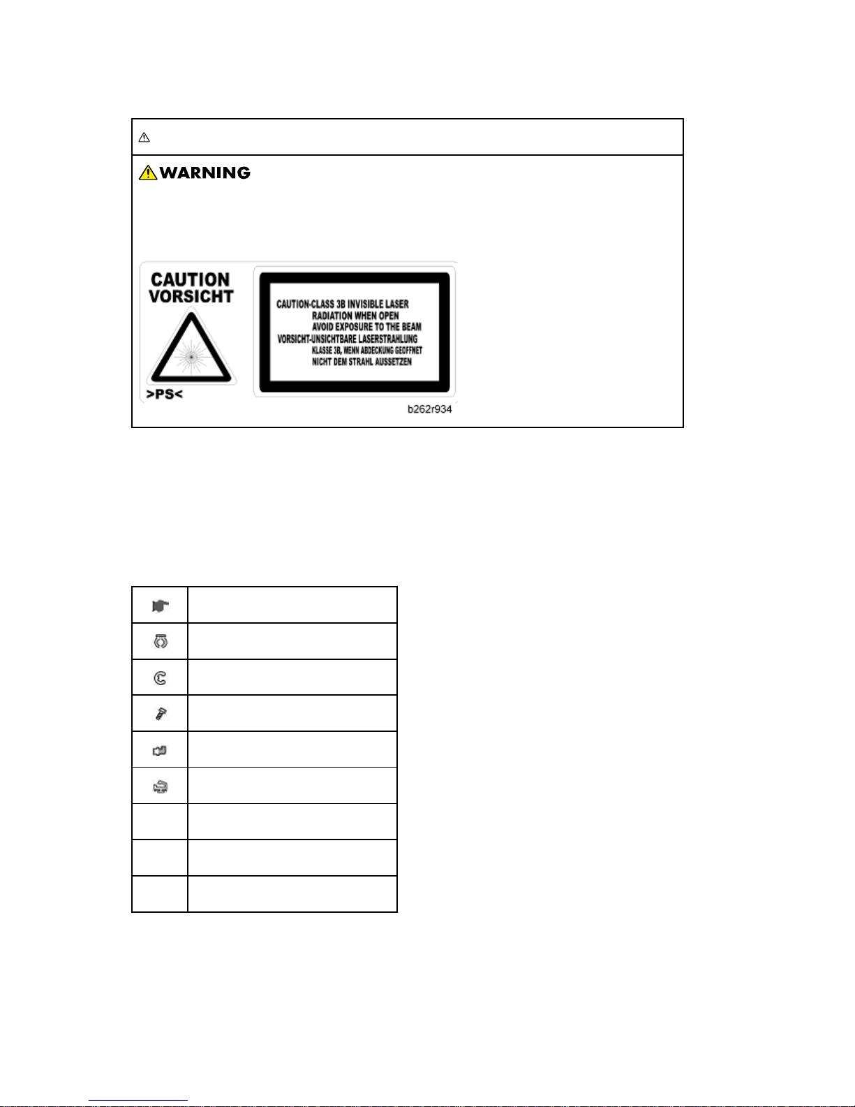
WARNING FOR LASER UNIT
Turn off the main switch before attempting any of the procedures in the Laser
Unit section. Laser beams can seriously damage your eyes.
CAUTION MARKING:
Symbols and Abbreviations
This manual uses several symbols and abbreviations. The meaning of those symbols and
abbreviations is as follows:
See or Refer to
Clip ring
E-ring
Screw
Connector
Clamp
SEF Short Edge Feed
LEF Long Edge Feed
- Core T echnology manual
Page 16

Cautions, Notes, etc.
The following headings provide special information:
Failure to obey warning information could result in serious injury or death.
Obey these guidelines to ensure safe operation and prevent minor injuries.
This information provides tips and advice about how to best service the machine.
Page 17

PRODUCT INFORMATION
REVISION HISTORY
Page Date Added/Updated/New
None
Page 18

Page 19

Specifications
SM 1-1 D127/D128
Product
Information
1. PRODUCT INFORMATION
1.1 SPECIFICATIONS
See "Appendices" for the following information:
General Specifications
Supported Paper Sizes
Page 20
Machine Configuration
D127/D128 1-2 SM
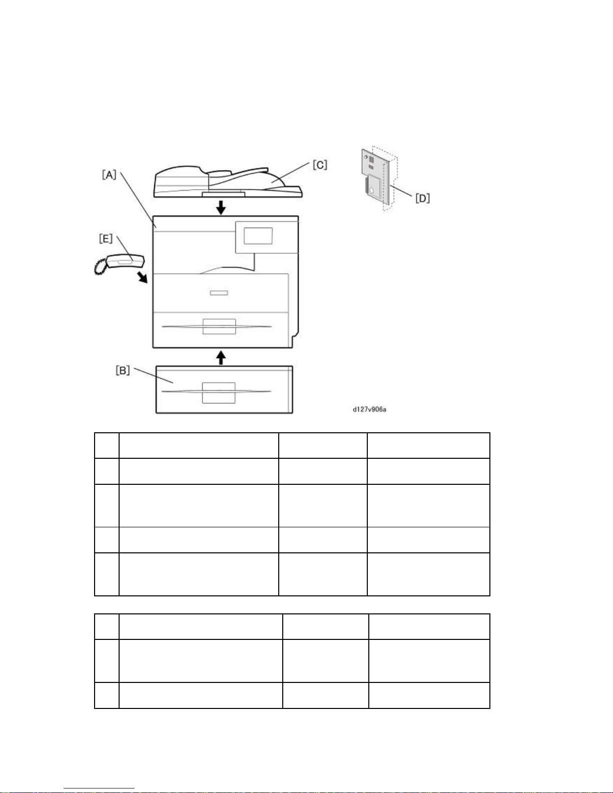
1.2 MACHINE CONFIGUR ATION
1.2.1 MAINFRAME
Standard Component Machine Code Remarks
1 Copier [A] D127/D128 -
2 ARDF [C] D606
Standard expect for EU
Option for EU
3 Platen Cover D607 Standard for EU
4 Fax Unit [D] D655
Standard only for D128
Option only for D127
Optional Component s Machine Code Remarks
5 500-sheet Paper Feed Unit [B] D661
Two units can be added
at maximum.
6 Handset [F] D645 NA only
Page 21
Machine Configuration
SM 1-3 D127/D128
Product
Information
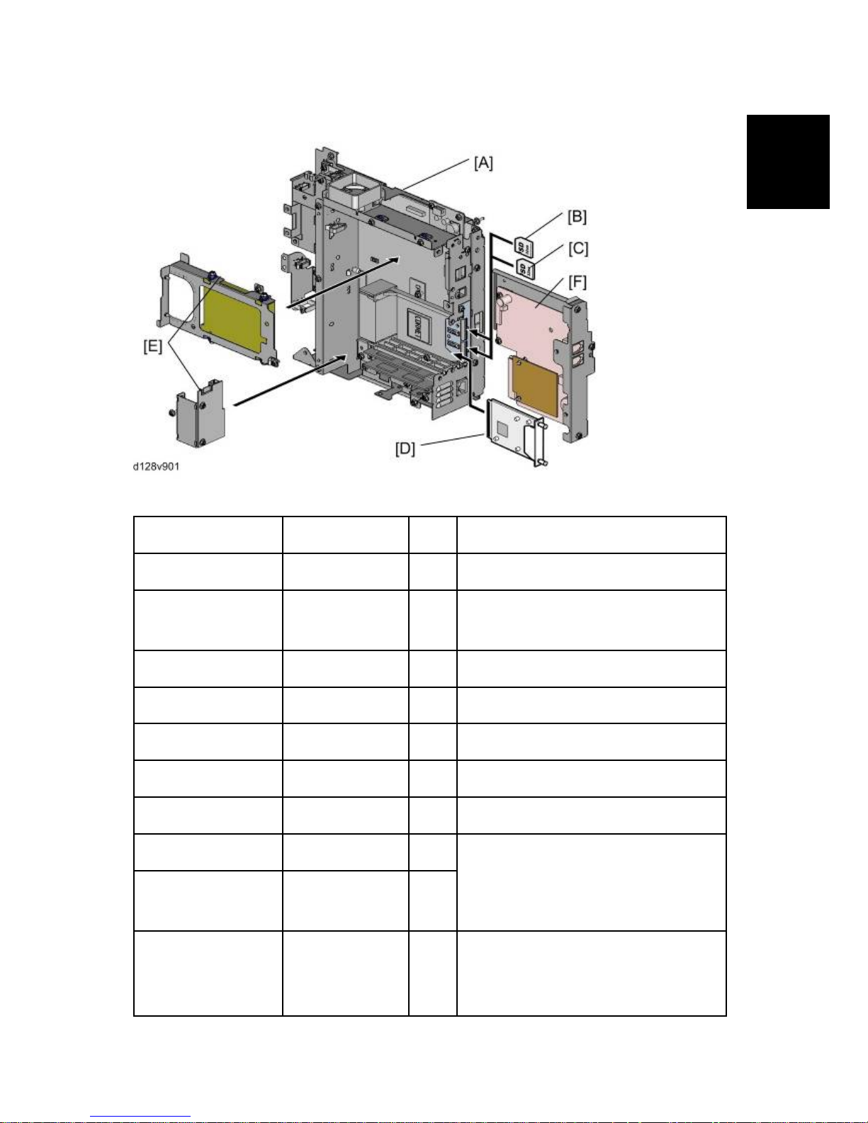
1.2.2 SYSTEM COMPONENTS
Item Machine Code Remarks
Controller Box - [A] Standard
Printer/Scanner unit D468 [B]
SD card for the Printer/Scanner Unit
Standard
FAX Option D655 [F]
FAX Connection Unit D660 [B]
Browser Unit D656 [B]
VM Card D656 [C] In SD slot 2 (lower)
Net Ware D659 [C] SD Card for Net Ware printing Type 1
IEEE 1284 B679 [D]
One from the two
Gigabit Ethernet
Board
G874 [D]
HDD D659 [E]
Optional HDD with Interface board
Merge the Security Card into the
Printer/Scanner SD card.
Page 22
Overview
D127/D128 1-4 SM
1.3 OVERVIEW
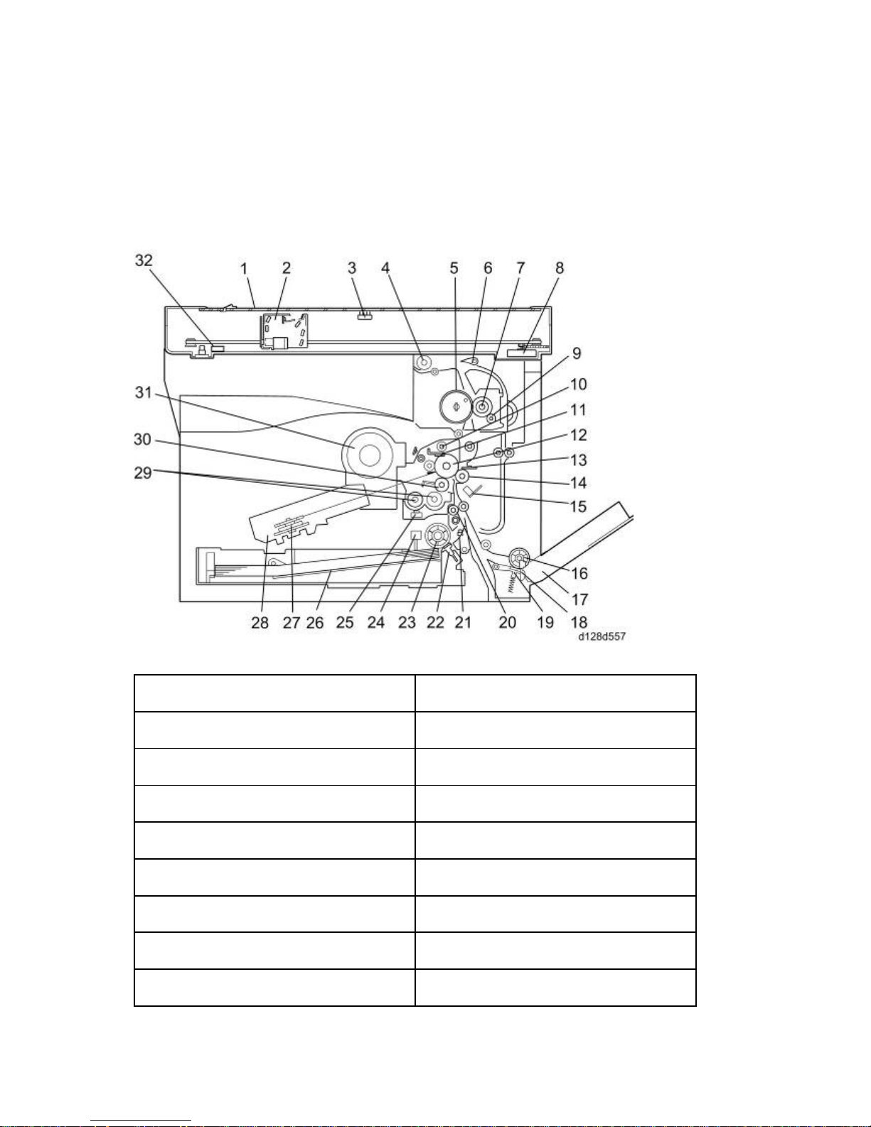
1.3.1 COMPONENT LAYOUT
Mainframe
1. Exposure Glass 17. Bypass Tray
2. LED Unit 18. Bypass Paper End Sensor
3. Platen Cover Sensor 19. Bypass Friction Pad
4. Exit Ro ller 20. Registration Roller
5. Hot Roller 21. Registration Sensor
6. Exit Sensor 22. (Main) Friction Pad
7. Pressure Roller 23. Paper Feed Roller
8. Scanner Motor 24. Paper End Sensor
9. Cleaning Web Roller 25. TD (Toner Density) Sensor
Page 23
Overview
SM 1-5 D127/D128
Product
Information
10. Toner Collection Coil 26. Bottom Plate
1 1. Cleaning Blade 27. Polygon Mirror Motor
12. OPC drum 28. Laser Unit
13. Discharge Plate 29. Mixing Augers
14. Transfer Roller 30. Development Roller
15. ID (Image Density) Sensor 31. Toner Supply Bottle
16. Bypass Paper Feed Roller 32. Scanner HP Sensor
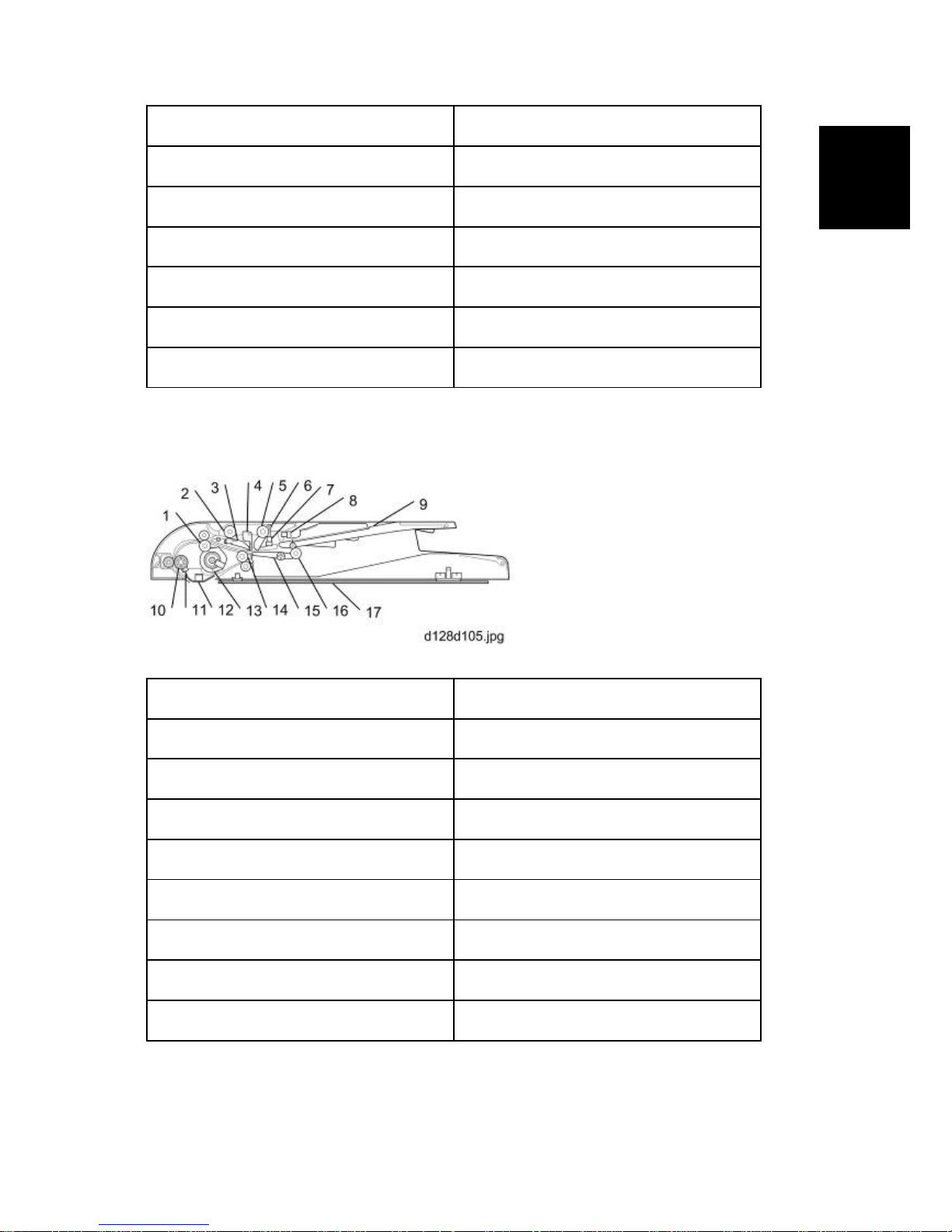
ARDF
1. Pull-out Roller 10. Registration Roller
2. Feed Roller 11. Registration Sensor
3. Friction Pad 12. Scanner Guide
4. Paper Stopper 13. ARDF drive motor
5. Pick-up Roller 14. Exit Roller
6. Original Set Feeler 15. Junction Gate
7. Original Set Sensor 16. Inverter Roller
8. Upper Cover Sensor 17. Platen Sheet
9. Original Set Tray
Page 24
Overview
D127/D128 1-6 SM
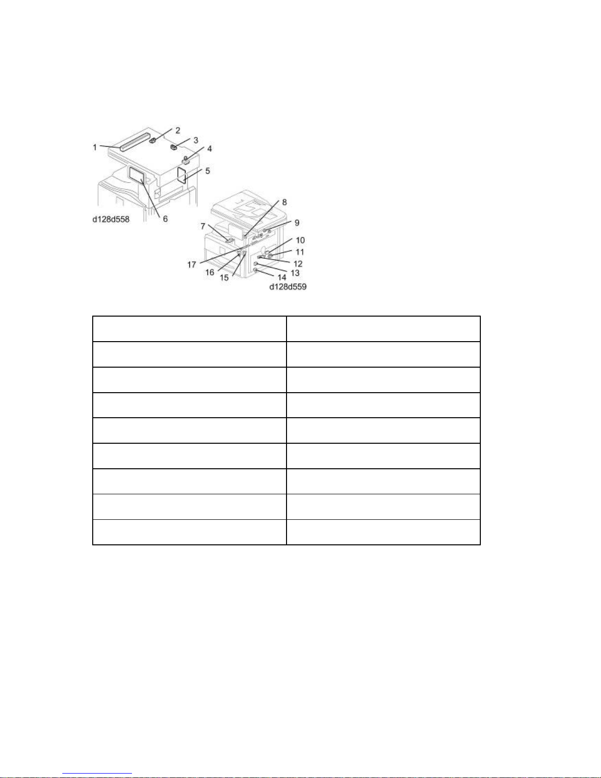
1.3.2 ELECTRICAL COMPONENTS
Electrical Components 1
1. LED Unit 10. ID (Image Density) Sensor
2. Scanner HP Sensor 1 1. Registration Sensor
3. Platen Cover Sensor 12. Paper End Sensor
4. Scanner Motor 13. Toner Density Sensor
5. High-V oltage Power Supply Board 14. Bypass Paper End Sensor
6. Operation Panel Board 15. Right Door Safety Switch
7. Polygon Mirror Motor 16. Front Door Safety Switch
8. LD Unit 17. Quenching Lamp
9. Exit Sensor
Page 25
Overview
SM 1-7 D127/D128
Product
Information
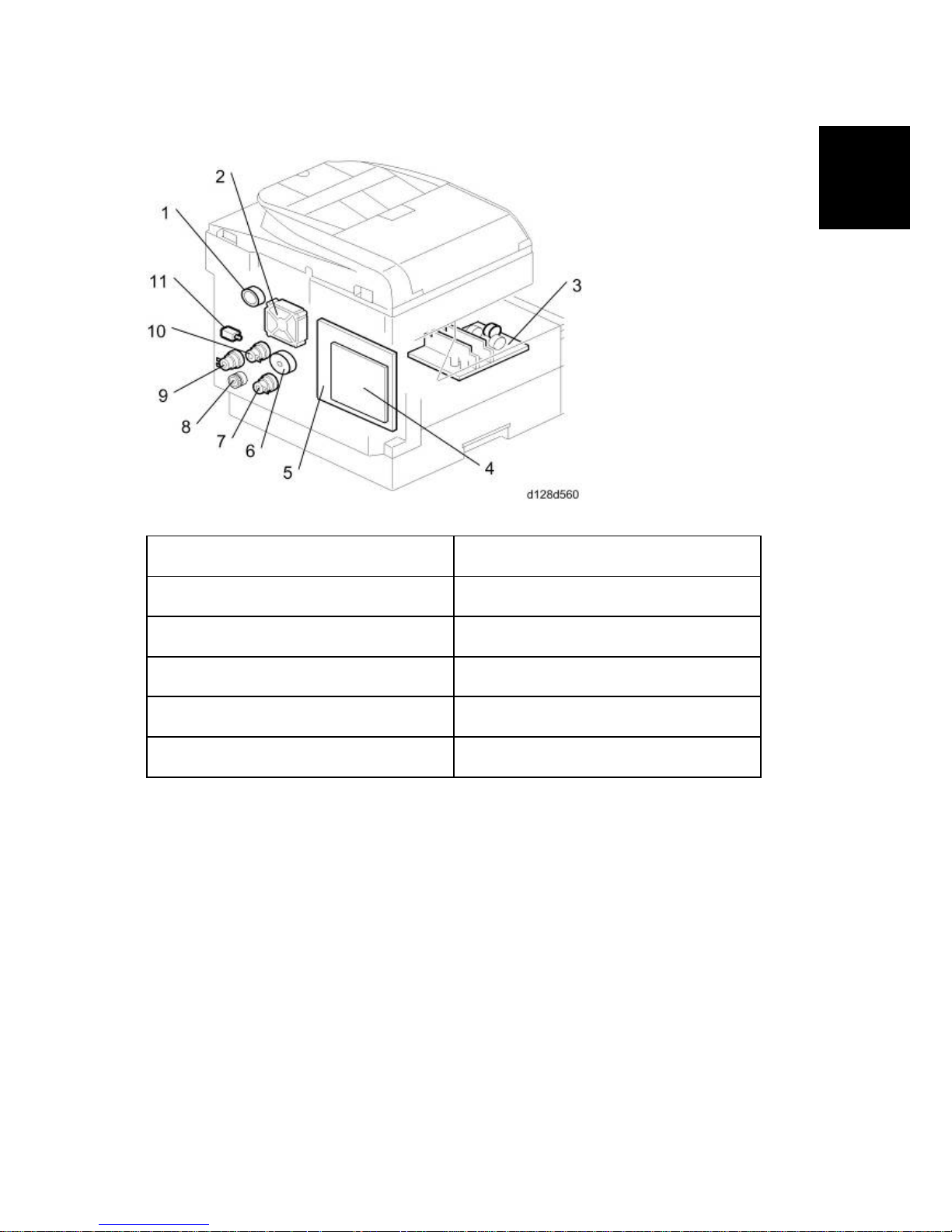
Electrical Components 2
1. Duplex Motor 7. Paper Feed Clutch
2. Exhaust Fan 8. Toner Supply Motor
3. PSU 9. Bypass Feed Clutch
4. Controller Board 10. Registration Clutch
5. BICU 11. Fusing Solenoid
6. Main Motor
Page 26
Overview
D127/D128 1-8 SM
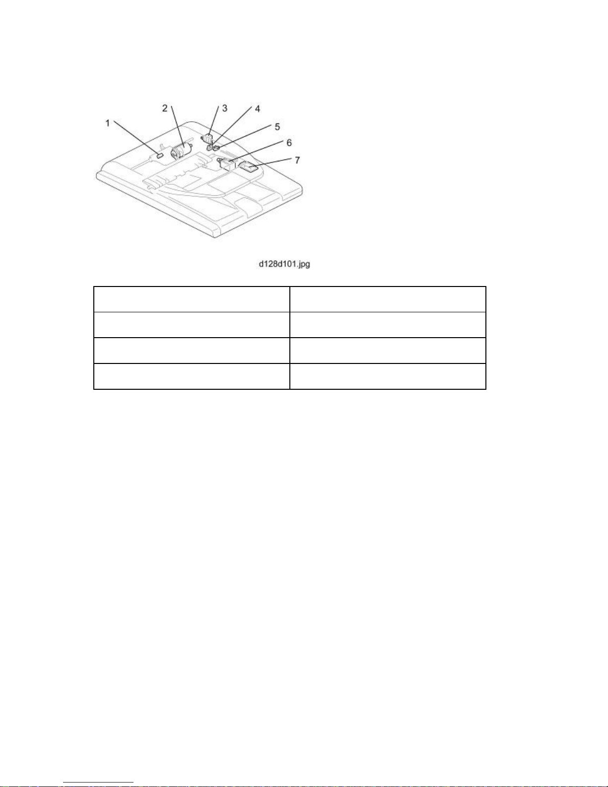
ARDF
1. Registration Sensor 5. Upper Cover Sensor
2. ARDF Drive Motor 6. Junction Gate Solenoid
3. Pick-up Solenoid 7. ARDF Relay Board
4. Original Set Sensor
Page 27
Overview
SM 1-9 D127/D128
Product
Information
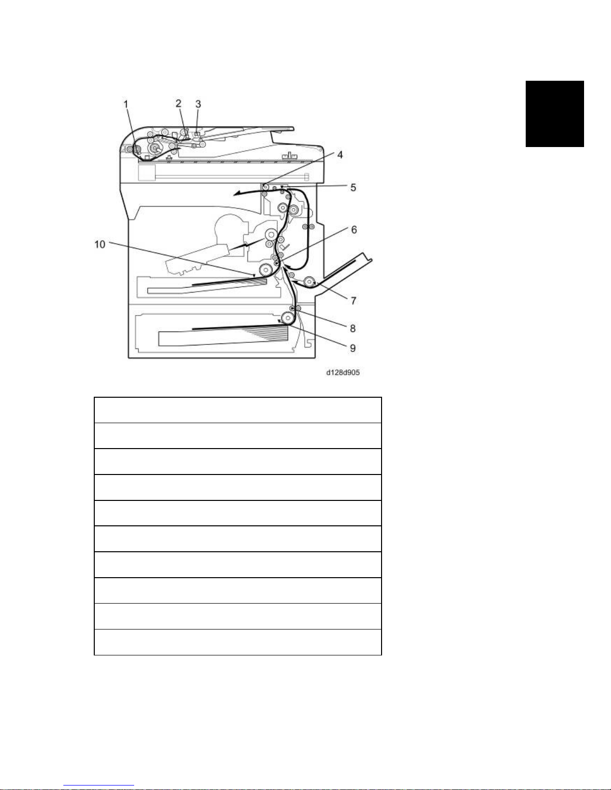
1.3.3 PAPER PATH
1. Original Registration Sensor (Document Feeder)
2. Original Set Sensor (Document Feeder)
3. Upper Cover Sensor (Document Feeder)
4. Exit Sensor
5. Paper Path Sensor
6. Registration Sensor
7. By-pass Paper End Sensor
8. Paper Feed Sensor (Optional Tray)
9. Paper End Sensor (Optional Tray)
10. Paper End Sensor
Page 28
Overview
D127/D128 1-10 SM
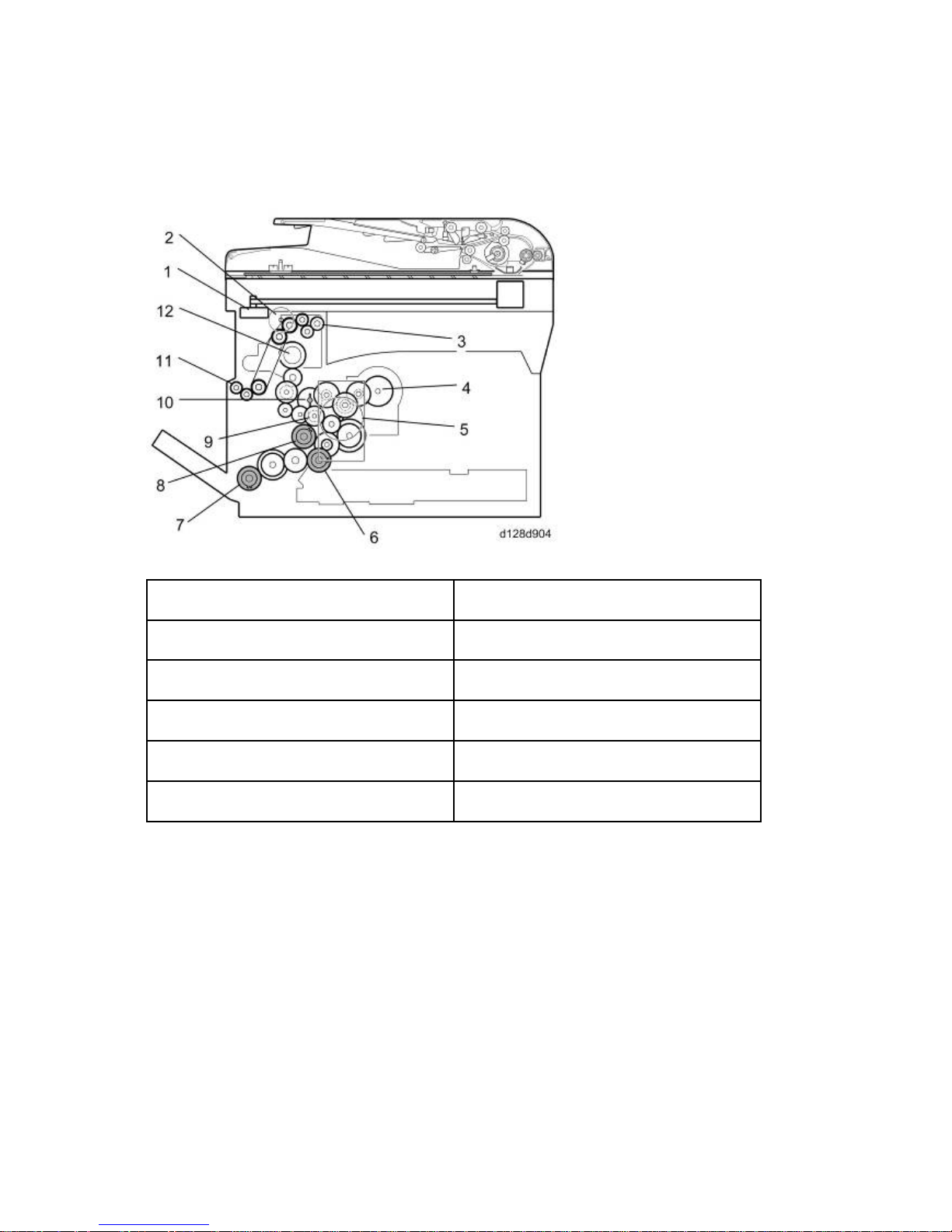
1.3.4 DRIVE LAYOUT
Mainframe
1. Scanner Motor 7. Bypass Feed Clutch
2. Duplex motor 8. Registration Clutch
3. Exit Ro ller 9. Developer Driver Gear
4. Toner Supply Motor 10. Drum Drive Gear
5. Main Motor 1 1. One-way Gear (Duplex Unit)
6. Paper Feed Clutch 12. Fusing Drive Gear
Page 29
Overview
SM 1-11 D127/D128
Product
Information
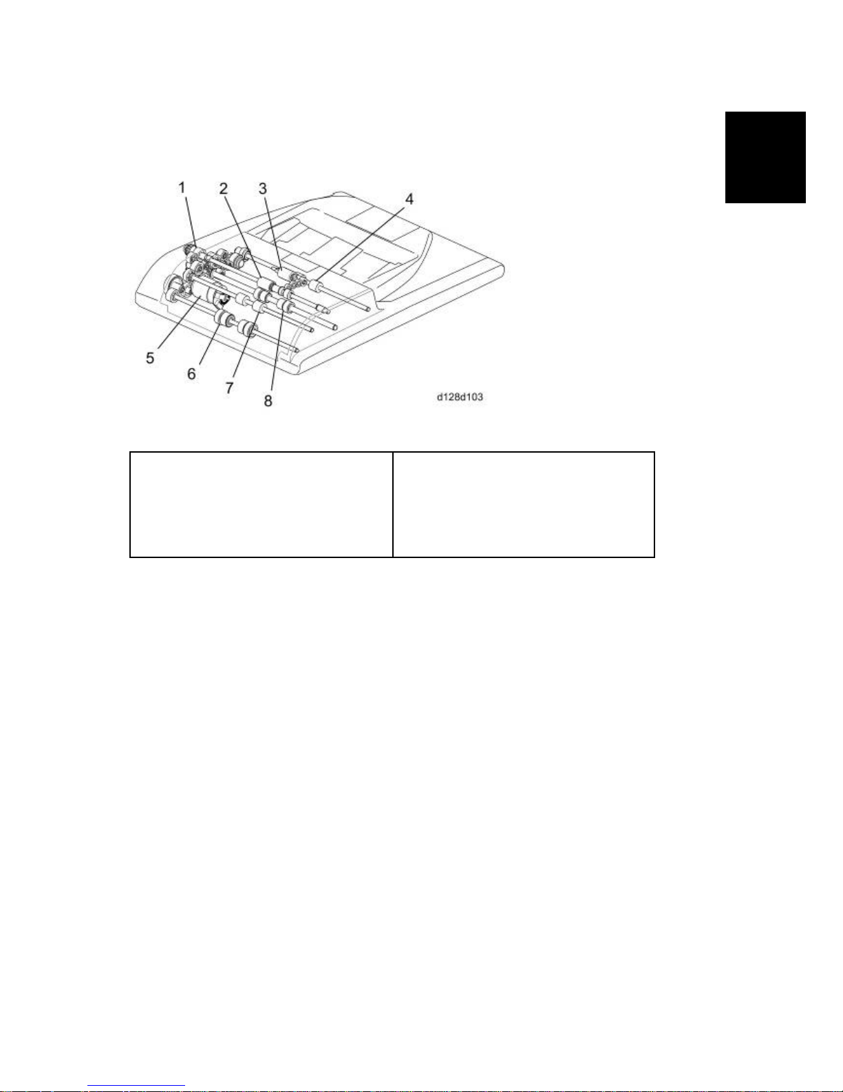
ARDF
1. DF Feed Clutch
2. Feed Roller
3. Pick-up Roller
4. Inverter Roller
5. DF Feed Motor
6. Registration Roller
7. Pull-out Roller
8. Exit Ro ller
DF Feed Motor [5]: Drives the feed, pull-out, pick-up, and registration and inverter rollers.
Page 30

Guidance for Those Who are Familiar with Predecessor Products
D127/D128 1-12 SM
1.4 GUIDANCE FOR THOSE WHO ARE FAMILIAR WITH
PREDECESSOR PRODUCTS
The D127/D128 range of machines is the successor model to the D115/D116 range of machines.
If you have experience with the predecessor line, the following information may be of help when
you read this manual.
Differences from Predecessor Products
D127/D128 D115/D116
Security Card (HDD
Encryption and Data
Overwrite Security Unit)
Standard Standard only for D115
Copying Speed
30cpm: Memory copy
30cpm: ADF 1 to 1
20cpm: Memory copy
16cpm: ADF 1 to 1
The following parts are unique for D127/D128. When replacing the following parts, use
the parts specified for each model. DO NOT mix up the following parts for D115/D116
and D127/D128. Otherwise, both of the machine operation and output quality are not
guaranteed.
1. LED Scanning Unit (Scanner Unit)
2. Laser Unit (Writing Unit)
3. ARDF
4. Pressing Roller (Fusing Unit)
5. Toner Bottle (Toner Supply Unit)
6. Operation Panel
7. Bank Unit Motor (Optional Bank Unit)
8. One Chip Microcomputer (Engine Control)
Page 31

INSTALLATION
REVISION HISTORY
Page Date Added/Updated/New
None
Page 32

Page 33

Installation Cautions
SM 2-1 D127/D128
Installation
2. INSTALLATION
2.1 INS TALLATION CAUTIONS
Before installing an optional unit, do the following:
Print out all messages stored in the memory, all user-programmed items, and a system
parameter list.
If there is a printer option on the machine, print out all data in the printer buffer.
Turn off the main switch and disconnect the power cord, the telephone line, and the
network cable.
Page 34

Installation Requirements
D127/D128 2-2 SM
2.2 INSTALLATION REQUIREMENTS
2.2.1 ENVIRONMENT
–Temperature and Humidity Chart–
Temperature Range: 10°C to 32°C (50°F to 89.6°F)
Humidity Range: 15% to 80% RH
Ambient Illumination: Less than 1,500 lux (Do not expose to direct sunlight.)
Ventilation: Room air should turn over at least 3 times/hr/person
Ambient Dust: Less than 0.1 mg/m
3
Do not install the machine where it will be exposed to direct sunlight or to direct airflow (from a
fan, air conditioner, air cleaner, etc.).
Do not install the machine where it will be exposed to corrosive gas.
Place the machine on a firm and level base.
Do not install the machine where it may be subjected to strong vibration.
Do not install the machine at any location over 2,000 m (6,500 ft.) above sea level.
2.2.2 M ACHINE LEVEL
Front to back: Within 5 mm (0.2") of level
Right to left: Within 5 mm (0.2") of level
Page 35

Installation Requirements
SM 2-3 D127/D128
Installation
2.2.3 MINIMUM OPERATIONAL SPACE REQUIREMENTS
Place the machine near the power source, providing clearance as shown.
A: Front – 750 mm (29.6")
B: Left – 100 mm (3.9")
C: Rear – 100 mm (3.9")
D: Right – 100 mm (3.9")
E: Depth – 450 mm (17.7")
F: Width – 476 mm (19.1")
The 750-mm front space indicated above is sufficient to allow the paper tray to be pulled
out. Additional space is required to allow an operator to stand at the front of the machine.
Actual minimum space requirement for left, rear, and right sides is 10mm (0.4") each, but
note that this will not allow room for opening of the bypass tray, right door or ARDF unit.
Page 36

Installation Requirements
D127/D128 2-4 SM
2.2.4 POWER REQUIREMENTS
Make sure that the wall outlet is near the machine and easily accessible. After completing
installation, make sure the plug fits firmly into the outlet.
Avoid multiple connections to the same power outlet.
Be sure to ground the machine.
Input voltage:
North America: 120 – 127 V, 60 Hz, 15 A
Europe: 220 – 240 V, 50/60 Hz, 10 A
Image quality guaranteed at rated voltage ± 10%.
Operation guaranteed at rated voltage ± 15%.
Page 37

Copier
SM 2-5 D127/D128
Installation
2.3 COPIER
2.3.1 ACCESSORY CHECK
Printer/Scanner (D127)/ Scanner and Fax Model (D128)
Description Q'ty
Operating Instructions – Book (-17, -29) 1 set
Operating Instructions – CD ROM (-17, -29) 1
Handset Bracket (-17) 1
Modular Cable (-17) 1
EMC Caution Sheet (-27) 1
EULA Sheet (-27) 1
Caution Sheet (-27) 1
Operation Panel Key Name Sign (-17,-21,-27,-29) 1
PFU Size And Drawer Num Decal (-17,-21,-27,-29) 1
FAX Masking Decal (D12727,D12729) 1
Printer/Scanner Accessories (-17,-21,-27,-29) 1 set
Power Supply Cord (-17,-21,-27,-29) 1
Installation Procedure Book (-17,-27,-29) 1
Quick Guide (-17,-29) 1
Machine Num Decal (-17,-21,-27,-29) 1
Under Communication Sign Decal (-27) 1
Page 38

Copier
D127/D128 2-6 SM
Install ati on Pr oce dur e
Make sure that the copier remains unplugged during installation.
1. Remove the all strips of tape.
2. Remove the bag, SMC, padding [A] and A3 sheet of paper [B] on the exposure glass.
3. Fold the SMC and put it in the back of the front door.
Power supply cord is attached on the back of the main machine.
4. Open the front door [D].
5. Lift lever [E], press in on latch [F] and pull the bottle holder [G] out. (You do not need to pull it
completely out of the machine.)
6. Take a new bottle of toner, and shake it several times.
Page 39

Copier
SM 2-7 D127/D128
Installation
7. Remove the outer cap [H].
Do not remove the inner cap [I].
8. Load the bottle on the holder.
Do not forcefully turn the toner bottle on the holder. After you turn on the main power
switch, the copier sets the bottle in place.
9. Push the bottle holder back into the machine.
10. Press the latch [J] down to lock the holder.
1 1. Remove the tapes [K].
12. Remove the padding [L].
13. Pull each tabbed strip [M] out of the PCU with one hand, supporting the PCU with the other.
Do not pull both strips at the same time, as this could damage the PCU.
14. Close the front door.
Page 40

Copier
D127/D128 2-8 SM
15. Pull out the paper tray, and remove the tape securing the end fence in the compartment.
16. Push the bottom plate down, and then load the paper.
17. Adjust the side fences. If you load paper shorter than A4, set the end fence in the correct
position.
18. Push the tray back into the copier.
19. Attach the appropriate tray number decal and paper-size decal to the paper tray [N].
20. Install optional units (if any).
21. Attach the ferrite core [O] to the end of the network cable [P] when connecting the cable.
Page 41

Copier
SM 2-9 D127/D128
Installation
22. Attach the ferrite core to the telephone line in the same manner as step 21.
23. Connect the telephone line to the "LINE" jack.
The end of the ferrite core must be about 9 cm (3.6") from the end of the cable. (EU, AP,
CHN)
24. Plug in the machine and turn on the main power switch [Q].
25. Select the language used in the operation panel as necessary (
> Language).
Interface settings
1. Start the SP mode.
2. Select SP5-985-001 (NIC setting) and change the setting value to "1" (ON).
3. Select SP5-985-002 (USB setting) and change the setting value to "1" (ON).
4. Turn the main switch off and on.
Copier settings
1. Start the SP mode.
2. Select SP5-801-001 and execute the initialization.
3. Exit the SP mode, and then start the UP mode.
4. Select the "@Remote Service" ("User Tool" > "System Settings > Administrator Tools" >
"Extended Security" > @Remote Service") and select "Do not Prohibit".
5. Exit the UP mode, and then start the SP mode.
6. Select SP5-907-001 and specify the "Plug & Play".
7. Select SP5-302-002 and specify the time zone.
8. Select SP5-307-001, 003, and 004 and specify the daylight-saving-time settings.
9. Exit the SP mode and turn the main switch off and on.
10. S tart the UP mode.
11. S pecify the date and time with "Set Date" or "Set Time" (User Tool" > "System Settings" >
"Timer Settings" > "Set Date" or "Set Time").
12. Turn the main switch off and on.
13. Check the operations.
14. Make a full size copy, and check if the side-to-side and leading edge registrations are correct.
If they are not, adjust the registrations.
Page 42

Copier
D127/D128 2-10 SM
Fax Settings
Initializing the Fax unit
When you press the Fax key for the first time after installation, the error "SRAM problem occurred
/ SRAM was formatted" will show on the LCD for initializing the program of the fax unit. Turn the
main power switch off/on to clear the error display.
If another error occurs after initialization, this can be a functional problem.
1. Select fax SP1-101-016 and specify the country code.
2. Select fax SP3-101-001 and specify the service station.
2.3.2 OPTIONAL HANDSET
Accessory Check
Check that you have the components and accessories.
No. Description Q'ty
1 Handset 1
2 Handset cradle 1
3 Screws 2
4 Handset curly cord with core 1
5 Handset bracket 1
Page 43

Copier
SM 2-11 D127/D128
Installation
Install ati on Pr oce dur e
1. Make two holes [A] through which the screws fasten the handset bracket to the main machine.
(Just penetrate with a screw driver)
You should detach the tray cover and make holes on it. Or you might damage the PSU.
2. Attach the handset bracket [B] to the side of the tray cover. (
x 2)
3. Remove the label from the handset cradle [C].
4. Attach the cradle [C] to the handset bracket (
x 2).
5. Reattach the label.
6. Set the handset on the cradle.
7. Connect the core attached handset cable to the "TEL" jack.
Page 44

Paper Tray Unit (D661)
D127/D128 2-12 SM
2.4 PAPER TRAY UNIT (D661)
2.4.1 ACCESSORY CHECK
Confirm that you have these accessories.
Description Q'ty
1. Paper-size decals 1 sheet
2. Installation Procedure (for service person) 1
2.4.2 INSTALLATION PROCEDURE
1. Turn off the main switch of the copier and unplug the power cord before you start the
installation procedure.
2. You need two or more persons to lift the copier. The copier is highly unstable when
lifted by one person, and may cause human injury or property damage.
3. Do not lift the copier with the paper feed unit installed. The handle and grips may be
damaged.
1. Remove the tapes [A].
Page 45

Paper Tray Unit (D661)
SM 2-13 D127/D128
Installation
2. Pull the paper tray part way out of the unit, remove the tape and cardboard [A], and push the
tray back in.
3. Set the copier onto the paper tray unit.
Page 46

Paper Tray Unit (D661)
D127/D128 2-14 SM
When installing a second paper tray unit, place on the first paper tray unit before placing
the copier onto the pair of paper tray units.
4. Remove the paper tray(s) from the paper tray unit(s).
5. Load paper into the paper tray(s). Adjust the side and end fences as necessary. If loading
81/2"x 14" paper, remove the end fence and set it into the special compartment.
6. Set the paper tray(s) back into the paper tray unit(s).
7. Stick on the appropriate tray-number decal(s) and paper-size decal(s), at the locations
indicated in the illustration.
Page 47

Paper Tray Unit Heater
SM 2-15 D127/D128
Installation
2.5 PAPER TRAY UNIT HEATER
The paper tray unit heater is installed in different place depending on the number of installed
paper tray units (Two units can be installed at a maximum).
The operation system doesn't work when more than three of the paper tray units are
installed.
2.5.1 ACCESSORY CHECK
Confirm that you have the accessories listed below.
Description Q'ty
1. Heater fastening screw 2
2. Grounding wire and Harness cover fastening screw 7
3. Washer 7
4. Spring washer 7
5. Joint bracket fastening screw 8
6. Clamp (Large) 2
7. Clamp (Mid) 5
8. Clamp (Small) 2
9. Edge saddle 1
Page 48

Paper Tray Unit Heater
D127/D128 2-16 SM
Description Q'ty
10. Joint bracket (Front) 4
1 1. Joint bracket (Rear) 2
12. Heater Harness (Long) 1
13. Heater Harness (Mid) 1
14. Heater Harness (short) 1
15. Grounding wire (Long) 1
16. Grounding wire (Short) 1
17. Harness cover 1
18. Guard 1
19. Heater bracket (NA:Blue, EU:Red) 1
20. High temperature caution decal 1
Page 49

Paper Tray Unit Heater
SM 2-17 D127/D128
Installation
2.5.2 INSTALLATION PROCEDURE (FOR ONE OF PTU INSTALLED
MACHINE)
Unplug the main machine's power cord before starting the following procedure.
1. Remove the paper tray unit from the copier if it is already installed.
2. Remove the rear cover [1] from the paper tray unit (
x 2).
Right screw on the picture is a shoulder screw.
3. Fasten the heater [2] (
x 2).
4. Put the clamps (Small) [3] in the holes
5. Joint the connector [4] to the heater harness (Short) [5].
6. Pass the heater harness (Short) [5] through the hole [6].
7. Attach the heater harness (Short) through the clamps as shown.
Page 50

Paper Tray Unit Heater
D127/D128 2-18 SM
8. Attach the harness cover [7] (
x 2, Washer x 2, Spring Washer x 2).
9. Remove the rear cover [8] (
x 5) and the copy tray [9] ( x 1)
10. Remove the controller box [10] (
x 2, x 6).
Page 51

Paper Tray Unit Heater
SM 2-19 D127/D128
Installation
1 1. Remove the support bracket [11] (
x 3).
12. Attach the heater harness (Long) [12] to the connector [13] on the board.
13. Attach the clamp (Large) [14]
14. Lead the heater harness (Long) [12] through the clamp (Large) [14] toward inner side of the
copier as shown.
15. Attach the clamp (Large) [15].
16. Pass the heater harness through the hole [16] to the rear of the copier.
17. Attach the grounding wire (Long) [17] (
x 1, Washer x1, Spring washer x1).
Page 52

Paper Tray Unit Heater
D127/D128 2-20 SM
18. Pass the grounding wire (Long) [17] through the hole [16] to the rear of the copier.
19. Mount the copier on the paper tray unit [18].
20. Put the heater harness (Long) in the hole [19].
Be sure to put the heater harness (Long) in the hole on keeping the end of the heater
harness (Long) horizontally long. This makes insertion easy.
21. Pass the support bracket between the copier and the heater harness (Long) on keeping the
end of the heater harness (Long) in the hole.
To do step 21 easily, be sure not to pass the heater harness (Long) completely thorough
the hole [19] at the step of 20.
22. Attach the edge saddle [20] to the support bracket.
23. Attach the heater harness (Long) and the grounding wire (Long) through the edge saddle as
shown.
24. Pass the grounding wire (Long) through the hole.
25. Pull the heater harness (Long) and the grounding wire (Long) to the paper tray unit side.
Page 53

Paper Tray Unit Heater
SM 2-21 D127/D128
Installation
26. Attach the grounding wire (Long) [21] ( x 1, Washer x1, Spring washer x1)
27. Attach two of the clamps (Mid) [22] [23].
28. Attach the clamp (Mid) [24].
29. Connect the heater harness (Long) to the heater harness (Short).
30. Attach the heater harness through the clamps as shown.
Be sure to make the bind attached on the heater harness upper than the clamp (Mid) [22]
[24].
31. Remove the drawer from the paper tray unit.
32. Attach the caution decal [25] in the bottom of the paper tray unit.
33. Reassemble the copier.
34. Plug in the power cord, and check the operation.
2.5.3 INSTALLATION PROCEDURE (FOR TWO OF PTU INST A LLED
MACHINE)
Unplug the main machine's power cord before starting the following procedure.
1. Remove the upper and the lower paper tray unit from the copier if it is already installed.
Page 54

Paper Tray Unit Heater
D127/D128 2-22 SM
2. Remove the rear cover [1] from two of the paper tray units ( x 4).
Right screw on the picture is a shoulder screw.
3. Attach the heater [2] to the lower paper tray unit (
x 2).
4. Put the clamps (Small) [3] in the holes.
5. Joint the connector [4] to the heater harness (Mid) [5].
6. Pass the heater harness (Mid) [5] through the hole [6].
7. Attach the heater harness (Mid) through the clamps as shown.
8. Attach the harness cover [7]. (
x 2, Washer x 2, Spring Washer x 2)
Page 55

Paper Tray Unit Heater
SM 2-23 D127/D128
Installation
9. Attach the guard [8] to the top face of the upper paper tray unit. (
x 1, Washer x 1, Spring
Washer x 1)
10. Remove the rear cover [9] (
x 5) and the copy tray [10] ( x 1).
1 1. Remove the controller box [11] (
x 2, x 6).
Page 56

Paper Tray Unit Heater
D127/D128 2-24 SM
12. Remove the support bracket [12] (
x 3).
13. Attach the heater harness (Long) [13] to the connector [14] on the board.
14. Attach the clamp (Large) [15]
15. Lead the heater harness (Long) [13] through the clamp (Large) [15] toward inner side of the
copier as shown.
16. Attach the clamp (Large) [16].
17. Pass the heater harness through the hole [17] to the rear of the copier.
18. Attach the grounding wire (Long) [18] (
x 1, Washer x1, Spring washer x1)
Page 57

Paper Tray Unit Heater
SM 2-25 D127/D128
Installation
19. Pass the grounding wire (Long) [18] through the hole [17] to the rear of the copier.
20. Mount the copier on two of the paper tray units [19].
21. Put the heater harness (Long) in the hole [20].
Be sure to put the heater harness (Long) in the hole on keeping the end of the heater
harness (Long) horizontally long. This makes insertion easy.
22. Pass the support bracket between the copier and the heater harness (Long) on keeping the
end of the heater harness (Long) in the hole.
To do step 22 easily, be sure not to pass the heater harness (Long) completely thorough
the hole [20] at the step of 21.
23. Attach the edge saddle [21] to the support bracket.
24. Attach the heater harness (Long) and the grounding wire (Long) through the edge saddle as
shown.
25. Pass the grounding wire (Long) through the hole.
26. Pull the heater harness (Long) and the grounding wire (Long) to the paper tray unit side.
27. Remove the hole cover [22] of the upper paper tray unit. (
x 1)
Page 58

Paper Tray Unit Heater
D127/D128 2-26 SM
28. Attach the grounding wire (Long) [23] (
x 1, Washer x1, Spring washer x1).
29. Attach the grounding wire (Short) between [24] to [25] through the hole. (
x 2, Washer x2,
Spring washer x2).
30. Attach three of the clamps (Mid) [26] [27] [28].
31. Attach the clamp (Mid) [29] [30].
32. Connect the heater harness (Long) to the heater harness (Mid).
33. Attach the heater harness through the clamps as shown.
Be sure to make the bind attached on the heater harness upper than the clamp (Mid) [29]
[30].
34. Remove the drawer from the lower paper tray unit.
35. Attach the caution decal [31] in the bottom of the lower paper tray unit as shown.
36. Reassemble the copier.
37. Plug in the power cord, and check the operation.
Page 59

Paper Tray Unit Heater
SM 2-27 D127/D128
Installation
2.5.4 JOINT BRACKET (JOINT THE COPIER AND THE UPPER PTU)
1. Remove each of the drawers.
2. Insert the joint bracket (Front) [1] into the slot as the arrow shows and fasten (
x 2)
3. Attach the joint bracket (Rear) [2] as shown. (
x 2)
The red arrow on the picture above shows the convex side of the screw hole. This is the
important clue to attach the bracket correctly.
Page 60

Paper Tray Unit Heater
D127/D128 2-28 SM
2.5.5 JOINT BRACKET (JOINT THE UPPER AND THE LOWER PTU)
1. Attach the joint bracket (Front) [1] as shown. (
x 2)
2. Attach the joint bracket (Rear) [2] as shown. (
x 2)
The red arrow on the picture above shows the convex side of the screw hole. This is the
important clue to attach the bracket correctly.
Page 61

Controller Options
SM 2-29 D127/D128
Installation
2.6 CONTROL L ER OPTIONS
2.6.1 OVERVIEW
This machine has I/F card slots and SD card slots for optional I/F connections and applications.
I/F Card Slot
Slot [A] is used for one of the optional I/F connections: (IEEE1284, IEEE802.1 1a/g (Wireless
LAN) or Gigabit Ethernet).
SD Card Slot
Slot [1] is used for options provided on SD cards. The application SD card (Printer/Scanner or
Security Card) should be installed in Slot 1. If more than one application is to be used, move
the applications to the same SD card with SP5873.
Slot [2] is used for options provided on SD cards and servicing. The VM card must be
installed in Slot 2.
Page 62

Controller Options
D127/D128 2-30 SM
2.6.2 WIRELESS LAN (IEEE 802.11A/G) INSTALLATION
Unplug the machine power cord before starting the following procedure.
Accessories
Check the accessories and their quantities against the table below.
No. Description Q'ty
1 Wireless Adapter 1
2 Wireless LAN Card 1
3 LAN Card Cover 1
4 Caution Sheet 1
5 Label 1
Install ati on Pr oce dur e
1. Remove the interface cover [A] (
x 2).
2. Install the Wireless adaptor into I/F slot [B] (
x 2).
3. Install the Wireless LAN card in the wireless adaptor.
4. Attach the antenna cap to the wireless LAN card.
5. Turn on the main power switch.
6. Print out the configuration page (User Tools/Counter > Printer Features > List/Test Print), and
then check that this device is detected.
Page 63

Controller Options
SM 2-31 D127/D128
Installation
If reception is poor, you may need to move the machine:
Make sure that the machine is not located near an appliance or any type of equipment that
could generate a strong magnetic field.
Position the machine as close as possible to the access point.
SP Mode Settings for IEEE 802.11a/g Wireless LAN
The following SP commands can be set for IEEE 802.11a/g
SP No. Name Function
5840 004 SSID Used to confirm the current SSID setting.
5840 006 Channel MAX
Sets the maximum range of the channel settings for
the country.
5840 007 Channel MIN
Sets the minimum range of the channel settings
allowed for your country.
5840 011 WEP Key Select Used to select the WEP key (Default: 00).
2.6.3 IEEE 1284 INSTALLATION
Unplug the machine power cord before starting the following procedure.
Accessories
Check the accessories and their quantities against the table below.
No. Description Q'ty
1 IEEE1284 Interface Ass'y 1
2 UL Sheet 1
3 Caution Sheet 1
Page 64

Controller Options
D127/D128 2-32 SM
Install ati on Pr oce dur e
1. Remove the interface cover [A] (
x 2).
2. Install the IEEE 1284 board into I/F slot [B] (
x 2).
3. Turn on the main power switch.
4. Print out the configuration page (User Tools/Counter > Printer Features > List/Test Print), and
then check that this device is detected.
Page 65

Controller Options
SM 2-33 D127/D128
Installation
2.6.4 VM CARD TYPE S (D656)
Accessories
Check the accessories and their quantities against the table below.Accessories
No. Description Q'ty
1 VM SD Card 1
2 Decal 1
Installation
1. Remove the interface cover [A] (
x 1).
2. Switch the machine off.
3. Insert the SD card [A] into SD Slot 2 (lower).
Page 66

Controller Options
D127/D128 2-34 SM
This SD card must be inserted into Slot 2, the lower slot.
2.6.5 GIGABIT ETHERNET
Unplug the main machine power cord before you do the following procedure.
1. Remove the I/F-slot cover [A] (
x 2).
2. Install the Gigabit Ethernet board (Knob-screw x 2) into the I/F-slot [B].
3. Attach one ferrite core [A] to the end of the Ethernet interface cable, and then attach the other
ferrite core [B] about 10cm from the end of the Ethernet interface cable.
4. Connect the Ethernet interface cable to the Gigabit Ethernet port.
Make sure that the machine can recognize this option (see 'Check All Connections' at the end of
this section).
Page 67

Controller Options
SM 2-35 D127/D128
Installation
2.6.6 FAX OPTION (D655)
Fax Unit is option for D127 but standard for D128.
The bracket on which Fax Unit is mounted is embedded in the controller box.
Component Check
No. Description Q'ty
1 Fax Unit 1
2 Speaker 1
3 Insulating Sheet 1
4 Screw for Fax Unit 4
5 Screw (thin) for Speaker 2
6 Screw (thick) for Grounding Wire 2
7 Harness with Band 1
8 Ferrite Core (EU/AP/CN) 1
9 Decal (Super G3) 1
10 Grounding Wire 2
11 Bracket Guide 1
12 Core attached Telephone Cord (NA only) 1
13 Ferrite Core 1
Page 68

Controller Options
D127/D128 2-36 SM
Install ati on Pr oce dur e
1. Rear cover ( x 5)
2. Attach the Fax Unit [A] to the bracket [B] with placing the sheet [C] between the unit [A] and the
bracket [B]. (
x 4)
3. Attach the Bracket Guide [D] as shown.
4. Slot the bracket assembled in procedure 2 in between two of the guides as the blue arrow
shows.
5. Attach the large end of the Harness with the Band [E] and connect the small end to on the Fax
Unit [A] as the red arrows shows.
6. Attach the Speaker [F] and its connector to the large end of the Harness [E].
Page 69

Controller Options
SM 2-37 D127/D128
Installation
7. Attach the ferrite core [A] on the speaker harness within 50mm from the end of the controller
board. This prevents the harness from being involved in the fan [B].
Grounding Wi r e
Attach the grounding wire as shown.
[A] and [B] are attached with screws (thick) for the grounding wire.
[C] and [D] are with screws for the controller board cover.
Be sure to make [A], [B] and [C] attached in upward direction.
Page 70

Controller Options
D127/D128 2-38 SM
2.6.7 HDD OPTION (D659)
Component Check
No. Description Q'ty
1 HDD Unit 1
2 Screw 6
3 SAT Interface Board 1
4 Cable (Small) 1
5 Cable (Large) 1
Page 71

Controller Options
SM 2-39 D127/D128
Installation
Install ati on Pr oce dur e
1. Open the right door [A].
2. Interface cover [B] (
x 1)
3. Rear cover [C] (
x 5)
4. Controller box cover [A] (
x 11)
Page 72

Controller Options
D127/D128 2-40 SM
5. Remove three of the screws and pull the bracket as the arrow shows to detach the board [A].
6. Connect the HDD Unit [B] and SAT Interface Board [C] with the Cable (small) and the Cable
(large).
7. Install the HDD Unit [B] and the SAT Interface Board [C] in the controller board (
x 5).
Be sure to lead two of the cables over the HDD bracket to the SAT interface board [C].
This makes installation easy.
8. Reinstall the controller box cover and rear cover in the machine.
Turn the main power switch on.
9. Touch the “Format” button displayed with the message on start-up.
10. Turn the main power switch off/on after the message directs to do so.
Installing t he Securi ty Card
1. Insert the Security Card in the SD slot.
For D127, use slot 2 (lower) and merge the Security Card into the Printer/Scanner card
with SP5-873-001. Remove the Security Card from the SD slot 2 after moving the
security applications and keep the Security Card at a safe location.
For D128, use slot 1 (upper).
2. Enter the SP mode.
3. Input a machine serial number with SP 5811-001.
4. Go into the SP mode and push "EXECUTE" with SP5-878-001.
5. Select SP5878-002, and then press "Execute" on the LCD.
6. Exit the SP mode after "Completed" is displayed on the LCD.
Page 73

Controller Options
SM 2-41 D127/D128
Installation
Activating the Security Applications
1. Make sure that the following settings are not at their factory default values:
Supervisor login password
Administrator login name
Administrator login password
If any of these settings is at a factory default value, tell the customer these settings must be
changed before you do the installation procedure.
2. Make sure that "Admin. Authentication" is ON.
[System Settings] – [Administrator Tools] – [Administrator Authentication Management] [Admin. Authentication]
If this setting is OFF, tell the customer this setting must be ON before you do the installation
procedure.
3. Make sure that "Administrator Tools" is enabled (selected).
[System Settings] – [Administrator Tools] – [Administrator Authentication Management] [Available Settings]
If this setting is disabled (not selected), tell the customer this setting must be enabled
(selected) before you do the installation procedure.
4. Refer to the Security Reference for details about activating the security applications (HDD
Encryption Unit and DataOverwriteSecurity).
HDD Encryption Recovery from a Device Problem
The flowchart below shows the recovery possibility of the HDD encryption if one of devices related
with the HDD encryption is defective.
Page 74

Controller Options
D127/D128 2-42 SM
Restoring the Enc r ypt ion key
When replacing the controller board for a model in which the HDD encryption unit has been
installed, updating the encryption key is required.
1. Prepare an SD card which is initialized.
2. Make the "restore_key" folder in the SD card.
3. Make an "nvram_key.txt" file in the "restore_key" folder in the SD card.
4. Ask an administrator to input the encryption key (this has been printed out earlier by the user)
into the "nvram_key.txt" file.
5. Remove only the HDD unit.
6. Turn on the main power switch.
7. Confirm that the prompt on the LCD tells you to install the SD card (storing the encryption
key) in the machine.
8. Turn off the main power switch.
9. Insert the SD card that contains the encryption key into slot 1.
10. Turn on the main power switch, and the machine automatically restores the encryption key in
the flash memory on the controller board.
11. Turn off the main power switch after the machine has returned to normal status.
12. Remove the SD card from slot 1.
13. Reinstall the HDD unit.
Page 75

Controller Options
SM 2-43 D127/D128
Installation
Cleari n g the NVRAM
When replacing the controller board for a model in which the HDD encryption unit has been
installed and a customer has lost the encryption key, clearing the NVRAM is required to recover
the HDD encryption unit.
1. Prepare an SD card which is initialized.
2. Make the "restore_key" folder in the SD card.
3. Make an "nvram_key.txt" file in the "restore_key" folder in the SD card.
4. Input "nvclear" into the "nvram_key.txt" file.
5. Turn on the main power switch.
6. Confirm that the prompt on the LCD tells you to install the SD card (storing the encryption
key) in the machine.
7. Turn off the main power switch.
8. Insert the SD card that contains "nvclear" into slot 1.
9. Turn on the main power switch, and the machine automatically restores the encryption key in
the flash memory on the controller board.
10. Turn off the main power switch after the machine has returned to normal status.
11. Remove the SD card from slot 1.
12. Turn on the main power switch.
13. Initialize the NVRAM (SP5801-001) and HDD unit (SP5832-001) with SP mode.
14. The user must enable the HDD encryption unit with a user tool.
Page 76

Page 77

PREVENTIVE MAINTENANCE
REVISION HISTORY
Page Date Added/Updated/New
None
Page 78

Page 79

Maintenance Tables
SM 3-1 D127/D128
Preventive
Maintenance
3. PREVENTIVE MAINTENANCE
3.1 MAINTENANCE TABLES
See "Appendices" for the following information:
PM tables
Page 80

How to Clear the PM Counter
D127/D128 3-2 SM
3.2 HOW TO CLEAR THE PM COUNTER
Reset the PM counter after your maintenance work.
1. Activate the SP mode.
2. Select SP7-804-001.
3. Press the EXECUTE. The message "Completed" is displayed when the program ends
normally. An error message is displayed if the program ends abnormally.
4. Press the Exit to end the program.
Page 81

REPLACEMENT AND ADJUSTMENT
REVISION HISTORY
Page Date Added/Updated/New
None
Page 82

Page 83

Precautions
SM 4-1 D127/D128
Replacement
and
Adjustment
4. REPLACEMENT AND ADJUSTMENT
4.1 PRECAUTIONS
4.1.1 GENERAL
Turn off the main power switch and unplug the machine before starting replacement.
Before turning off the main power switch, check that no mechanical component is operating.
Mechanical components may stop out of their home positions if you turn off the main power switch
while they are operating. The component may be damaged if you try to remove it when it is not in
the home position.
4.1.2 LITHIUM BATTERIES
Incorrect replacement of lithium battery(s) on the controller or on the fax unit poses risk of
explosion. Replace only with the same type or with an equivalent type recommended by
the manufacturer. Discard used batteries in accordance with the manufacturer's
instructions.
4.1.3 HALOGEN-FREE CABLE
Use extreme caution while handling cables.
To comply with local regulations, halogen-free cables are used in this machine. Halogen-free
cables are environment-friendly, but no stronger than conventional cables. These cables may be
damaged in any of the following cases:
The cable is caught between hard objects such as brackets, screws, PCBs, and exterior
covers.
The cable is rubbed on a hard object such as brackets, screws, PCBs, and exterior covers.
The cable is scratched with a hard object such as brackets, screws, PCBs, exterior covers,
screwdrivers, and fingernails.
4.1.4 STATIC ELECTRICITY
Always touch a grounded surface to discharge static electricity from your hands before you handle
SD cards, printed circuit boards, or memory boards.
Page 84

Special Tools and Lubricants
D127/D128 4-2 SM
4.2 SPECIAL TOOLS AND LUBRICANTS
Part Number Description Q'ty
B6455010 SD Card 1
52039502 Silicon Grease G-501 1
B6795100 Plug-IEEE1284 Type C 1
Page 85

Exterior Covers and Operation Panel
SM 4-3 D127/D128
Replacement
and
Adjustment
4.3 EXTERIOR COVERS AND OPERATION PANEL
4.3.1 RE AR COVER
1. Open the right door [A].
2. Interface cover [B] (
x 1)
3. Open the right door [A].
4. Rear cover [C] (
x 5)
4.3.2 COPY TRAY
Make sure that the cables under the copy tray are in place before reassembling the
copier. If these cables are caught between the copy tray and the inner cover, they may be
severely damaged.
1. Open the front door [A].
2. Copy tray [B] (
x1)
Page 86

Exterior Covers and Operation Panel
D127/D128 4-4 SM
4.3.3 OPERATION PANEL
1. Remove the Scanner front cover [A].(Hook)
2. Remove the Right front cover [B].(Hook)
3. Remove the screws and the harnesses showed above for detaching the scanner unit.
4. Scanner unit [C] (
x 5, x 4)
5. Operation panel [D] (
x 5, x 2)
Page 87

Exterior Covers and Operation Panel
SM 4-5 D127/D128
Replacement
and
Adjustment
4.3.4 RIGHT DOOR
1. Open the right door [A].
2. Release the strap [B].
3. Open the door fully and pull out.
4. Right door (
x 1)
4.3.5 BYP ASS TRAY
1. Press the stopper rails [A] inward.
2. Pull out with pressing the rails.
3. Bypass Tray (Hook)
Page 88

Exterior Covers and Operation Panel
D127/D128 4-6 SM
4.3.6 P LATEN COVER AND ARDF SENSOR
1. Scanner Cover (
p.4-7 " Scanner Cover and Exposure Glass")
2. Platen cover sensor [A] (
x 1, hook)
Page 89

Scanner Unit
SM 4-7 D127/D128
Replacement
and
Adjustment
4.4 SCANNER UNIT
To clean the mirrors and lenses, use a blower brush or wet cotton.
4.4.1 SCANNER COVER AND EXPOSURE GLASS
Exposure glass is united with Scanner cover.
To clean the exposure glass, use alcohol or glass cleaner.
1. Platen cover or ARDF (
p.4-46 "ARDF Unit")
2. Scanner front cover [A] (Hook)
The front scanner cover is attached by 2 of the hooks the picture [1] shows. Pulling the
cover downward to keep the hooks off while removing, makes detaching easy.
3. Scanner cover [B] (
x 7, Hook)
Page 90

Scanner Unit
D127/D128 4-8 SM
4.4.2 LED UNIT
Do not disassemble the LED Unit. The LED Unit is precision adjusted before shipment.
Do not touch the screws on the CCD. The CCD is precision adjusted before shipment.
Do not wipe the oil coated on the guide rod off. The oil doesn't exist in service parts.
1. Scanner Cover and Exposure Glass (
p.4-7 " Scanner Cover and Exposure Glass")
2. Remove the long bracket [A] and the guide rod bracket [B]. (
x 4)
3. Lift the guide rod [C] as the red arrow shows.
4. Put the belt [D] off as blue arrow shows to release the LED Unit [E] from the guide rod.
Do not loosen the paint-locked screws holding the lens in place.
After installing a new lens, carry out copy adjustments (
p.4-57 "Adjusting Copy
Image Area").
Page 91

Scanner Unit
SM 4-9 D127/D128
Replacement
and
Adjustment
4.4.3 SCANNER MOTOR
1. Push the spring [A] located on the opposite side of the scanner motor [B] to loosen the belt [C]
from the scanner motor gear.
2. Remove the screws on the top of the scanner motor [B] (
x 4).
3. Turn the scanner motor [B] back. Then remove the screws and the harness on the back (
x
2
x1).
4.4.4 SCANNER HP SENSOR
1. Rear cover (
p.4-3 "Rear Cover")
2. Scanner Cover and Exposure Glass (
Scanner Cover and Exposure Glass)
3. Two of the brackets [A] [B] and the rail [C] (
x 6)
4. Scanner HP sensor [D] (
x 1, x 1)
Page 92

Fusing
D127/D128 4-10 SM
4.5 FUSING
4.5.1 FUSING UNIT
Before handling the fusing unit, make sure that the unit is cool enough. The fusing unit
can be very hot.
1. Copy tray (
p.4-3 "Copy Tray")
2. Open the right door.
3. Connector cover [A] (
x 1)
When reinstalling, attach the ground wire.
4. Fusing unit [B] (
x 2, x 4)
4.5.2 EXIT SENSOR
1. Fusing unit (
p.4-10 "Fusing Unit")
2. Exit sensor [A] (
x 1)
Page 93

Fusing
SM 4-11 D127/D128
Replacement
and
Adjustment
4.5.3 HOT ROLLER STRIPPER PAWLS
Take care not to damage the hot roller stripper pawls and the tension springs.
1. Fusing unit (
p.4-10 "Fusing Unit")
2. Separate the fusing unit into two sections: the hot roller section [A] and the pressure roller
section [B] (
x 2).
After removing the screws, lower the pressure roller section about halfway and then slide it
toward the front side to detach it.
3. Support rollers [C]
4. Hot roller stri pper pawls [D]
Remove the spacer [E] (
x 1) if you are removing the hot roller assembly (
p.4-12 "Hot Roller and Fusing Lamp").
Page 94

Fusing
D127/D128 4-12 SM
4.5.4 HOT ROLLER AND FUSING LAMP
Do not touch the fusing lamp and rollers with your bare hands.
1. Hot roller stripper pawls and spacers (
p.4-11 "Hot Roller Stripper Pawls")
2. Hot roller assembly [A] (
x 2)
3. Fusing lamp [B]
When reassembling, check that the direction of the fusing lamp is correct.
4. Hot roller [C] (2 C-rings, 1 spacer, 1 gear, 2 bushings, 1 cover [D])
Reassembling
Be sure that:
The fusing lamp is positioned correctly.
The fusing lamp does not touch the internal part of the hot roller.
Page 95

Fusing
SM 4-13 D127/D128
Replacement
and
Adjustment
4.5.5 THERM OSWITCHES AND THERMISTOR
1. Hot roller assembly (
p.4-12 "Hot Roller and Fusing Lamp")
2. Thermoswitches [A] (
x 2 )
3. Thermistor [B] (
x 1)
Reassembling
Make sure of the following:
That the thermistor is in contact with the hot roller.
That the hot roller turns smoothly.
Do not recycle a thermoswitch that is already opened. Safety is not guaranteed if you do
this.
Page 96

Fusing
D127/D128 4-14 SM
4.5.6 PRESSURE ROLLER
1. Separate the fusing unit into two sections (
p.4-11 "Hot Roller Stripper Pawls").
2. Fusing entrance guide [A] (
x 1)
3. Two springs [B][C]
4. Two pressure arms [D][E]
5. Bushing [F]
6. Pressure roller [G]
Page 97

Fusing
SM 4-15 D127/D128
Replacement
and
Adjustment
4.5.7 FUSING NIP BAND CHECK BY-PASS (CHECKING THE NIP
BAND)
You can check the nip band to see if the fusing unit is in a good condition–especially, if the hot
roller and pressure roller are correctly installed.
1. Place an OHP sheet on the by-pass tray.
2. Activate the SP mode.
3. Select SP1-152-001.
4. The copier feeds the OHP sheet, and stops it between the hot roller and the pressure roller for
about 40 seconds.
5. Wait until the OHP sheet is output.
6. After output, quit the SP mode.
You see an opaque stripe on the OHP sheet. This is the trace of the nip band. The normal nip
band is symmetrical on the OHP sheet. Both ends are slightly thicker than the center.
There are no specifications or standards for the nip band of this copier.
Page 98

PCU and Quenching Lamp
D127/D128 4-16 SM
4.6 PCU AND QUENCHING LAMP
When handling the photo conductor unit (PCU), use caution:
Do not touch the OPC drum with your bare hands. When the OPC drum is unclean, clean it
with dry cloth, or clean it with wet cotton and wipe it with dry cloth.
Do not use alcohol or any other chemicals to clean the OPC drum. These substances
damage the OPC-drum surface.
Keep PCUs in a cool, dry place.
Do not expose the OPC to any corrosive gas such as ammonia.
Do not shake a used PCU. Remaining toner and developer may spill out.
Dispose of used PCUs in accordance with local regulations.
4.6.1 PCU
1. Open the right door.
The PCU may become stuck if you try to remove it while the front door is closed.
2. Open the front door.
3. Remove the toner bottle holder.
Clean all spilled toner off the toner bottle area and the inside of the front door.
4. Pull out the PCU [A] on pushing the part as the red arrow shows. (
x 1).
Page 99

PCU and Quenching Lamp
SM 4-17 D127/D128
Replacement
and
Adjustment
When reinstall the PCU, be sure to hook the PCU connector cable as shown above so as
not to damage the cable.
5. When having installed a new PCU, remove the Styrofoam and tags (
p.2-5 "Copier" in the
chapter "Installation").
Initialization
After replacement, Do “SP2801-001” to initialize the copier setting for PCU.
4.6.2 QUENCHING LAMP
1. PCU (
p.4-16 "PCU")
2. Remove the Lamp Shading [A] (Adhered)
3. Put the Quenching lamp [B] out as the blue arrow shows on pushing carefully as the red
arrow shows. (
x 1)
Page 100

Exhaust Fan and Main Motor
D127/D128 4-18 SM
4.7 EXHAUST FAN AND MAIN MOTOR
4.7.1 EXHAU ST F AN
1. Rear cover (
p.4-3 "Rear Cover")
2. Exhaust fan [A] (
x 2, x 1)
 Loading...