

Ricoh D096 Service Manual

D096
SERVICE MANUAL
005627MIU


D096
SERVICE MANUAL


D096
SERVICE MANUAL
005627MIU


It is the reader's responsibility when discussing the information contained
within this document to maintain a level of confidentiality that is in the best
interest of Ricoh Americas Corporation and its member companies.
NO PART OF THIS DOCUMENT MAY BE REPRODUCED IN ANY
F ASHION AND DISTRIBUTED WITHOUT THE PRIOR
PERMISSION OF RICOH AMERICAS CORPORATION.
All product names, domain names or product illustrations, including
desktop images, used in this document are trademarks, registered
trademarks or the property of their respective companies.
They are used throughout this book in an informational or editorial fashion
only and for the benefit of such companies. No such use, or the use of
any trade name, or web site is intended to convey endorsement or other
affiliation with Ricoh products.
© 2010 RICOH Americas Corporation. All rights reserved.


The Service Manual contains information
regarding service techniques, procedures,
processes and spare parts of office equipment
distributed by Ricoh Americas Corporation.
Users of this manual should be either service
trained or certified by successfully completing a
Ricoh Technical Training Program.
Untrained and uncertified users utilizing
information contained in this service manual to
repair or modify Ricoh equipment risk personal
injury, damage to property or loss of warranty
protection.
Ricoh Americas Corporation
WARNING


LEGEND
PRODUCT
CODE
COMPANY
GESTETNER LANIER RICOH SAVIN
D096 MP 1900 LD319 MP 1900 N/A
DOCUMENTATION HISTORY
REV. NO. DATE COMMENTS
*
04/2010 Original Printing


SM i D096
D096
TABLE OF CONTENTS
PRODUCT INFORMATION
1. PRODUCT INFORMATION ...........................................................1-1
1.1SPECIFICATIONS ..................................................................................... 1-1
1.2MACHINE CONFIGURATION ................................................................... 1-2
1.3GUIDANCE FOR THOSE WHO ARE FAMILIAR WITH PREDECESSOR
PRODUCTS ..................................................................................................... 1-3
1.4OVERVIEW ................................................................................................ 1-4
1.4.1 COMPONENT LAYOUT ................................................................... 1-4
1.4.2 PAPER PATH ................................................................................... 1-6
1.4.3 DRIVE LAYOUT ................................................................................ 1-7
INSTALLATION
2. INSTALLATION ............................................................................2-1
2.1INSTALLATION REQUIREMENTS ............................................................ 2-1
2.1.1 ENVIRONMENT ............................................................................... 2-1
2.1.2 MACHINE LEVEL ............................................................................. 2-2
2.1.3 MINIMUM SPACE REQUIREMENTS ............................................... 2-3
2.1.4 POWER REQUIREMENTS ............................................................... 2-3
2.2COPIER INSTALLATION ........................................................................... 2-4
2.2.1 POWER SOCKETS FOR PERIPHERALS ........................................ 2-4
2.2.2 ACCESSORY CHECK ...................................................................... 2-4
2.2.3 INSTALLATION PROCEDURE ......................................................... 2-5
2.3PLATEN COVER INSTALLATION ............................................................. 2-9
2.3.1 ACCESSORY CHECK ...................................................................... 2-9
2.3.2 INSTALLATION PROCEDURE ......................................................... 2-9
2.4ADF INSTALLATION ............................................................................... 2-10
2.4.1 ACCESSORY CHECK .................................................................... 2-10
2.4.2 INSTALLATION PROCEDURE ....................................................... 2-11
2.5ANTI-CONDENSATION HEATER INSTALLATION ................................. 2-14
2.6TRAY HEATER ........................................................................................ 2-15

D096 ii SM
2.6.1 TRAY HEATER ............................................................................... 2-15
2.7ACCESSIBILITY HANDLE INSTALLATION ............................................ 2-17
PREVENTIVE MAINTENANCE
3. PREVENTIVE MAINTENANCE ....................................................3-1
3.1PM TABLES ............................................................................................... 3-1
3.2HOW TO RESET THE PM COUNTER ...................................................... 3-2
REPLACEMENT AND ADJUSTMENT
4. REPLACEMENT AND ADJUSTMENT .........................................4-1
4.1GENERAL CAUTIONS .............................................................................. 4-1
4.1.1 PCU (PHOTOCONDUCTOR UNIT) .................................................. 4-1
4.1.2 TRANSFER ROLLER ....................................................................... 4-1
4.1.3 SCANNER UNIT ............................................................................... 4-1
4.1.4 LASER UNIT ..................................................................................... 4-2
4.1.5 FUSING UNIT ................................................................................... 4-2
4.1.6 PAPER FEED ................................................................................... 4-2
4.2SPECIAL TOOLS AND LUBRICANTS ....................................................... 4-3
4.3EXTERIOR COVERS & OPERATION PANEL .......................................... 4-4
4.3.1 REAR COVER .................................................................................. 4-4
4.3.2 COPY TRAY ..................................................................................... 4-4
4.3.3 UPPER COVERS ............................................................................. 4-5
4.3.4 LEFT COVER ................................................................................... 4-5
4.3.5 FRONT COVER ................................................................................ 4-6
4.3.6 FRONT RIGHT COVER .................................................................... 4-6
4.3.7 RIGHT REAR COVER ...................................................................... 4-7
4.3.8 RIGHT DOOR ................................................................................... 4-7
4.3.9 BY-PASS TRAY ................................................................................ 4-8
4.3.10 PLATEN COVER SENSOR .......................................................... 4-9
4.4SCANNER UNIT ...................................................................................... 4-10
4.4.1 EXPOSURE GLASS/DF EXPOSURE GLASS ................................ 4-10
4.4.2 LENS BLOCK ................................................................................. 4-11
4.4.3 LAMP STABILIZER BOARD AND EXPOSURE LAMP ................... 4-12
4.4.4 SCANNER MOTOR ........................................................................ 4-13
4.4.5 SCANNER HOME POSITION SENSOR......................................... 4-14

SM iii D096
4.4.6 ADJUSTING SCANNER POSITIONS ............................................. 4-15
4.5LASER UNIT ............................................................................................ 4-19
4.5.1 LOCATION OF CAUTION DECAL .................................................. 4-19
4.5.2 TONER SHIELD GLASS ................................................................. 4-20
4.5.3 LASER UNIT ................................................................................... 4-21
4.5.4 LD UNIT .......................................................................................... 4-22
4.5.5 POLYGONAL MIRROR MOTOR .................................................... 4-23
4.5.6 LASER UNIT ALIGNMENT ADJUSTMENT .................................... 4-24
4.6PCU SECTION......................................................................................... 4-26
4.6.1 PCU ................................................................................................ 4-26
4.6.2 TONER SUPPLY MOTOR .............................................................. 4-27
4.6.3 PICK-OFF PAWLS AND TONER DENSITY SENSOR ................... 4-28
4.6.4 OPC DRUM .................................................................................... 4-29
4.6.5 CHARGE ROLLER AND CLEANING BRUSH ................................ 4-30
4.6.6 CLEANING BLADE ......................................................................... 4-31
4.6.7 DEVELOPER .................................................................................. 4-32
4.6.8 AFTER REPLACEMENT OR ADJUSTMENT ................................. 4-33
4.7PAPER FEED SECTION ......................................................................... 4-34
4.7.1 PAPER FEED ROLLER .................................................................. 4-34
4.7.2 FRICTION PAD ............................................................................... 4-35
4.7.3 PAPER END SENSOR ................................................................... 4-35
4.7.4 EXIT SENSOR ................................................................................ 4-36
4.7.5 BY-PASS FEED ROLLER AND PAPER END SENSOR ................ 4-37
4.7.6 REGISTRATION ROLLER .............................................................. 4-38
4.7.7 BY-PASS PAPER SIZE SWITCH ................................................... 4-39
4.7.8 REGISTRATION CLUTCH .............................................................. 4-40
4.7.9 REGISTRATION SENSOR ............................................................. 4-40
4.7.10 PAPER FEED CLUTCH AND BY-PASS FEED CLUTCH ........... 4-41
4.7.11 PAPER SIZE SWITCH ................................................................ 4-42
4.8IMAGE TRANSFER ................................................................................. 4-43
4.8.1 IMAGE TRANSFER ROLLER ......................................................... 4-43
4.8.2 IMAGE DENSITY SENSOR ............................................................ 4-44
4.9FUSING ................................................................................................... 4-45
4.9.1 FUSING UNIT ................................................................................. 4-45
4.9.2 THERMISTOR ................................................................................ 4-45
4.9.3 FUSING LAMPS ............................................................................. 4-46

D096 iv SM
4.9.4 HOT ROLLER STRIPPER PAWLS ................................................. 4-47
4.9.5 HOT ROLLER ................................................................................. 4-47
4.9.6 THERMOSTAT ............................................................................... 4-48
4.9.7 PRESSURE ROLLER AND BUSHINGS ......................................... 4-49
4.9.8 NIP BAND WIDTH ADJUSTMENT ................................................. 4-50
4.9.9 CLEANING ROLLER ...................................................................... 4-51
4.10 OTHER REPLACEMENTS ................................................................. 4-52
4.10.1 QUENCHING LAMP ................................................................... 4-52
4.10.2 HIGH-VOLTAGE POWER SUPPLY BOARD ............................. 4-52
4.10.3 BICU (BASE-ENGINE IMAGE CONTROL UNIT) ....................... 4-53
4.10.4 MAIN MOTOR............................................................................. 4-53
4.10.5 LEFT EXHAUST FAN ................................................................. 4-54
4.10.6 PSU (POWER SUPPLY UNIT) ................................................... 4-54
4.10.7 GEARBOX .................................................................................. 4-55
4.11 COPY ADJUSTMENTS PRINTING/SCANNING ................................ 4-58
4.11.1 PRINTING ................................................................................... 4-59
4.11.2 SCANNING ................................................................................. 4-60
4.11.3 ADF IMAGE ADJUSTMENT ....................................................... 4-63
SERVICE TABLES
5. SERVICE TABLES........................................................................5-1
5.1SERVICE PROGRAM MODE .................................................................... 5-1
5.1.1 SP TABLES ...................................................................................... 5-1
5.1.2 HOW TO ENTER THE SP MODE .................................................... 5-1
5.2USING SP MODES .................................................................................... 5-3
5.2.1 ADJUSTING REGISTRATION AND MAGNIFICATION .................... 5-3
5.2.2 ID SENSOR ERROR ANALYSIS (SP 2221) ..................................... 5-4
5.2.3 MEMORY CLEAR ............................................................................. 5-5
5.2.4 INPUT CHECK (SP 5803) ................................................................. 5-7
5.2.5 OUTPUT CHECK (SP 5804) ........................................................... 5-12
5.2.6 SERIAL NUMBER INPUT (SP 5811) .............................................. 5-14
5.2.7 NVRAM DATA UPLOAD/DOWNLOAD (SP 5824/5825) ................. 5-15
5.2.8 FIRMWARE UPDATE PROCEDURE ............................................. 5-17
5.2.9 TEST PATTERN PRINT (SP 5902 1) ............................................. 5-19
5.2.10 PAPER JAM COUNTERS (SP 7504) ......................................... 5-21

SM v D096
5.2.11 SMC PRINT (SP 5990) ............................................................... 5-22
5.2.12 ORIGINAL JAM HISTORY DISPLAY (SP 7508)......................... 5-22
5.2.13 JAM HISTORY CODES .............................................................. 5-22
5.2.14 ADF APS SENSOR OUTPUT DISPLAY (SP 6901) .................... 5-23
TROUBLESHOOTING
6. TROUBLESHOOTING ..................................................................6-1
6.1SERVICE CALL CONDITIONS .................................................................. 6-1
6.2ELECTRICAL COMPONENT DEFECTS ................................................... 6-2
6.2.1 SENSORS ........................................................................................ 6-2
6.2.2 SWITCHES ....................................................................................... 6-4
6.3BLOWN FUSE CONDITIONS .................................................................... 6-5
6.4LED DISPLAY ............................................................................................ 6-6
6.4.1 BICU ................................................................................................. 6-6
ENERGY SAVING
7. ENERGY SAVING .........................................................................7-1
7.1ENERGY SAVE ......................................................................................... 7-1
7.1.1 ENERGY SAVER MODES ................................................................ 7-1
Timer Settings ...................................................................................... 7-2
Return to Stand-by Mode ..................................................................... 7-2
Recommendation ................................................................................. 7-2
7.1.2 ENERGY SAVE EFFECTIVENESS .................................................. 7-3
D096 SERVICE MANUAL APPENDICES
SEE D096 SERVICE MANUAL APPENDICES SECTION FOR DETAILED TABLE OF
CONTENTS
DF 2000 (B813)
SEE SECTION B813 FOR DETAILED TABLE OF CONTENTS


PRODUCT INFORMATION
APPENDIX: SPECIFICATIONS
B813 DOCUMENT FEEDER DF2000
INSTALLATION
APPENDIX: PREVENTIVE MAINTENANCE
PREVENTIVE MAINTENANCE
APPENDIX: TROUBLESHOOTING GUIDE
REPLACEMENT AND ADJUSTMENT
APPENDIX: SP MODE TABLES
SERVICE TABLES
TROUBLESHOOTING
ENERGY SAVING
TAB
POSITION 2
TAB
POSITION 1
TAB
POSITION 3
TAB
POSITION 4
TAB
POSITION 6
TAB
POSITION 5
TAB
POSITION 8
TAB
POSITION 7


Read This First
Safety Notices
Important Safety Notices
Prevention of Physical Injury
1. Before disassembling or assembling parts of the copier and peripherals, make sure
that the power cord is unplugged.
2. The wall outlet should be near the copier and easily accessible.
3. Note that some components of the copier and the paper tray unit are supplied with
electrical voltage even if the main power switch is turned off.
4. If a job has started before the copier completes the warm-up or initializing period, keep
hands away from the mechanical and electrical components because the starts
making copies as soon as the warm-up period is completed.
5. The inside and the metal parts of the fusing unit become extremely hot while the copier
is operating. Be careful to avoid touching those components with your bare hands.
Health Safety Conditions
Toner and d eveloper are non-toxic, but if you get either of them in your eyes by accident, it
may cause temporary eye discomfort. Try to remove with eye drops or flush with water as
first aid. If unsuccessful, get medical attention.
Observance of Electrical Safety Standards
The copier and its peripherals must be installed and maintained by a customer service
representative who has completed the training course on those models.
Safety and Ecological Notes for Disposal
1. Do not incinerate toner bottles or used toner. Toner dust may ignite suddenly when
exposed to an open flame.
2. Dispose of used toner, developer, and organic photoconductors in accordance with
local regulations. (These are non-toxic supplies.)
3. Dispose of replaced parts in accordance with local regulations.

Handling Toner
Work carefully when removing paper jams or replacing toner bottles or cartridges to
avoid spilling toner on clothing or the hands.
If toner is inhaled, immediately gargle with large amounts of cold water and move to a
well ventilated location. If there are signs of irritation or other problems, seek medical
attention.
If toner gets on the skin, wash immediately with soap and cold running water.
If toner gets into the eyes, flush the eyes with cold running water or eye wash. If there
are signs of irritation or other problems, seek medical attention.
If toner is swallowed, drink a large amount of cold water to dilute the ingested toner. If
there are signs of any problem, seek medical attention.
If toner spills on clothing, wash the affected area immediately with soap and cold water.
Never use hot water! Hot water can cause toner to set and permanently stain fabric.
Always store toner and developer supplies such as toner and developer packages,
cartridges, and bottles (including used toner and empty bottles and cartridges) out of
the reach of children.
Always store fresh toner supplies or empty bottles or cartridges in a cool, dry location
that is not exposed to direct sunlight.
Laser Safety
The Center for Devices and Radiological Health (CDRH) prohibits the repair of laser-based
optical units in the field. The optical housing unit can only be repaired in a factory or at a
location with the requisite equipment. The laser subsystem is replaceable in the field by a
qualified Customer Engineer. The laser chassis is not repairable in the field. Customer
engineers are therefore directed to return all chassis and laser subsystems to the factory or
service depot when replacement of the optical subsystem is required.
Use of controls, or adjustment, or performance of procedures other than
those specified in this manual may result in hazardous radiation exposure.
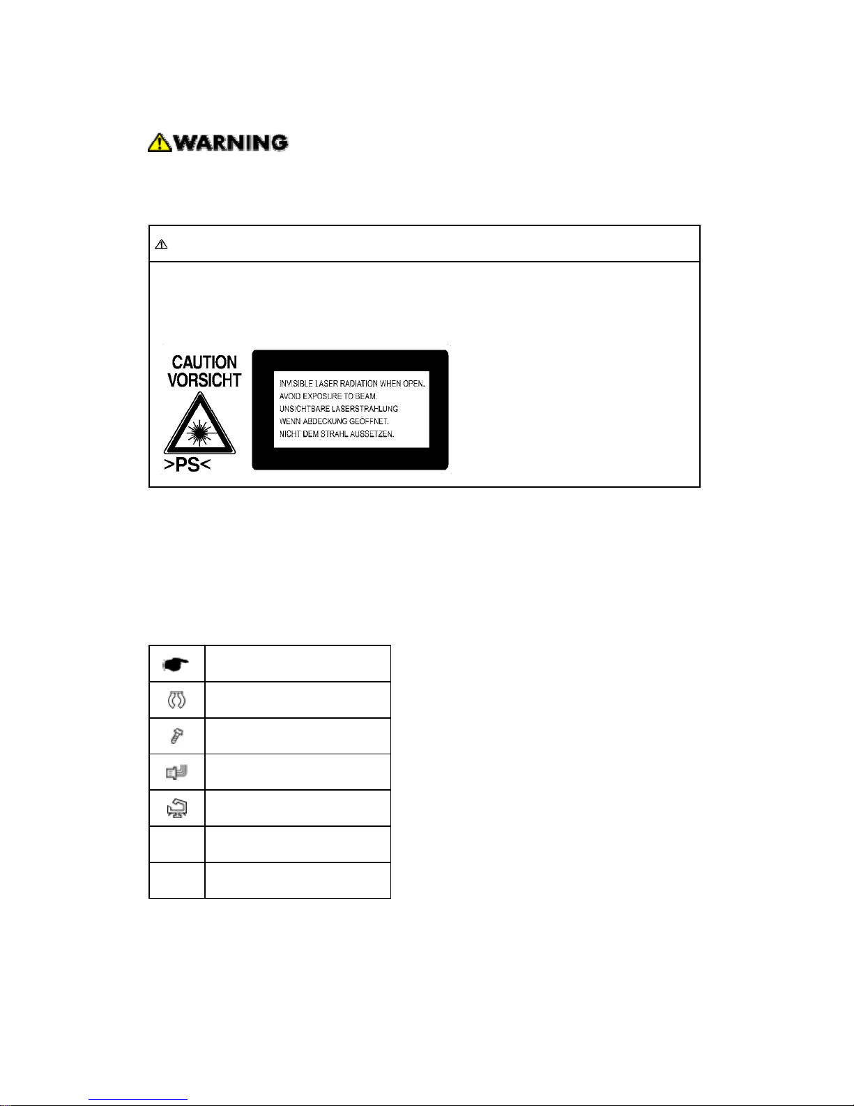
WARNING FOR LASER UNIT
WARNING: Turn off the main switch before attempting any of the procedures in the
Laser Unit section. Laser beams can seriously damage your eyes.
CAUTION MARKING:
Symbols and Abbreviations
This manual uses several symbols and abbreviations. The meaning of those symbols and
abbreviations are as follows:
See or Refer to
Clip ring
Screw
Connector
Clamp
SEF Short Edge Feed
LEF Long Edge Feed


PRODUCT INFORMATION
REVISION HISTORY
Page Date Added/Updated/New
None


Specifications
SM 1-1 D096
Product
Information
1. PRODUCT INFORMATION
1.1 SPECIFICATIONS
See "Appendices" for the following information:
General Specifications
Supported Paper Size
Optional Equipment
Machine Configuration
D096 1-2 SM
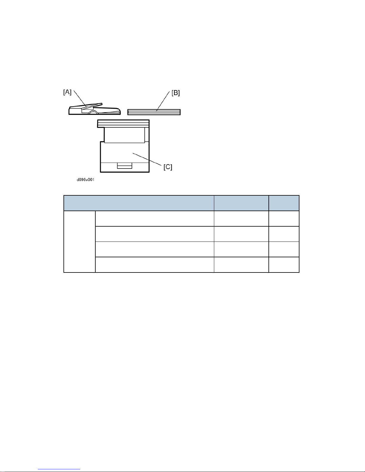
1.2 MACHINE CONFIGURATION
Unit/Component Machine Code Diagram
Copier
Copier (1-tray non-duplex model) D096 [D]
Platen cover (optional) B406 [B]
ADF (optional) B813 [A]
Accessibility Handle Type A (optional) B272 -

Guidance for Those Who are Familiar with Predecessor Products
SM 1-3 D096
Product
Information
1.3 GUIDANCE FOR THOSE WHO ARE FAMILIAR
WITH PREDECESSOR PRODUCTS
The D096 model is successor models to the B245 model. If you have experience with the
predecessor products, the following information will be of help when you read this manual.
Different Points from Predecessor Products
D096 B245
Duplex Not available Not available
Paper Tray One tray One tray
Printer/ Scanner Not available Not available
Fax Not available Not available
GDI Controller Not available Not available
GW Controller Not available Not available
APS (Mainframe) Not available Available
Copy Speed 19 cpm 15cpm
Overview
D096 1-4 SM
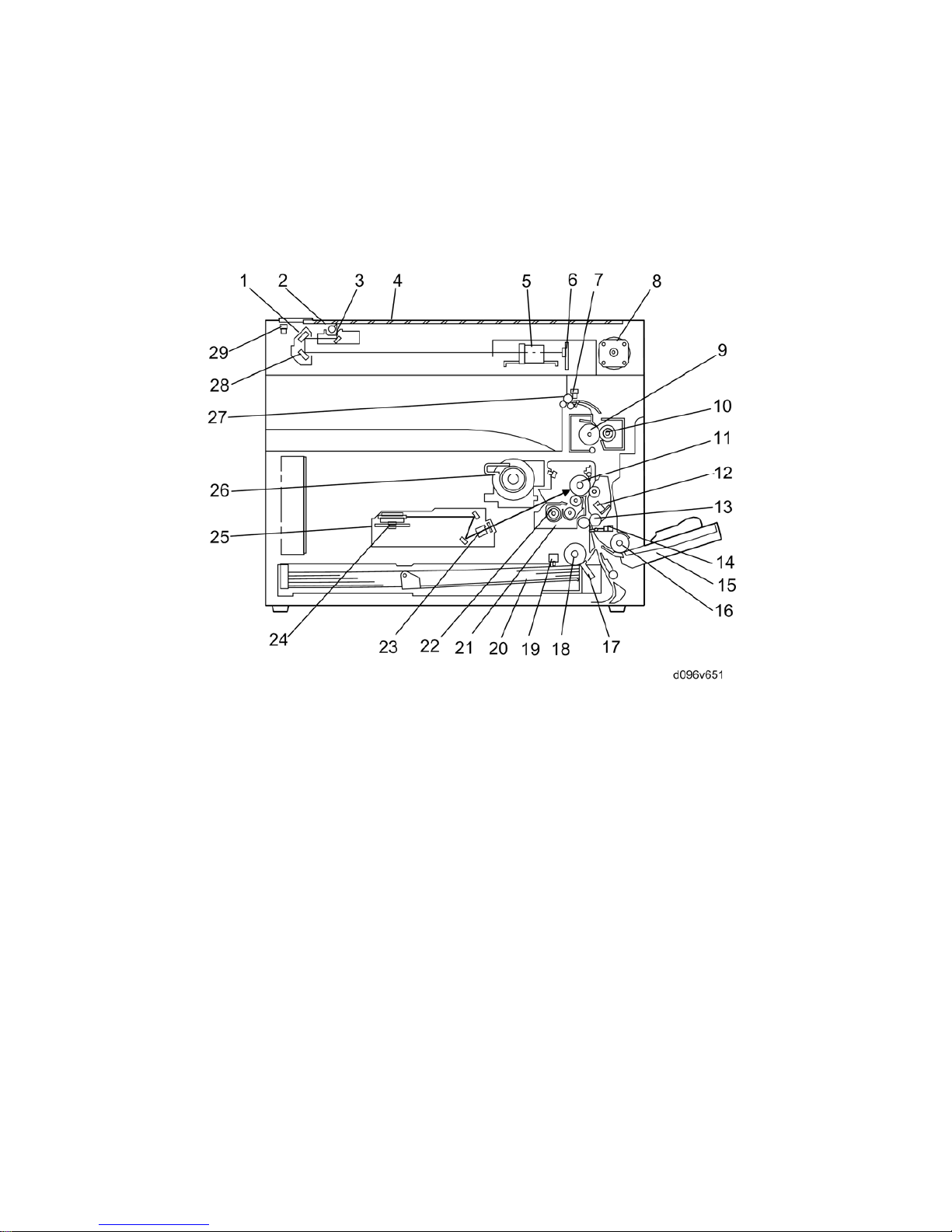
1.4 OVERVIEW
1.4.1 COMPONENT LAYOUT
 Loading...