

Page 1

Mail Box CS4010
Machine Code:
D708
Field Service Manual
May, 2016
Page 2

Page 3

Safety, Conventions, Trademarks
Conventions
Common Terms
This is a list of symbols and abbreviations used in this manual.
Symbol, Abbreviation Meaning
Blue screw
Bushing
C-ring
Connector
E-ring
Flexible film cable
Harness clamp
Hook
Screw
Spring
Timing belt
JG Junction Gate
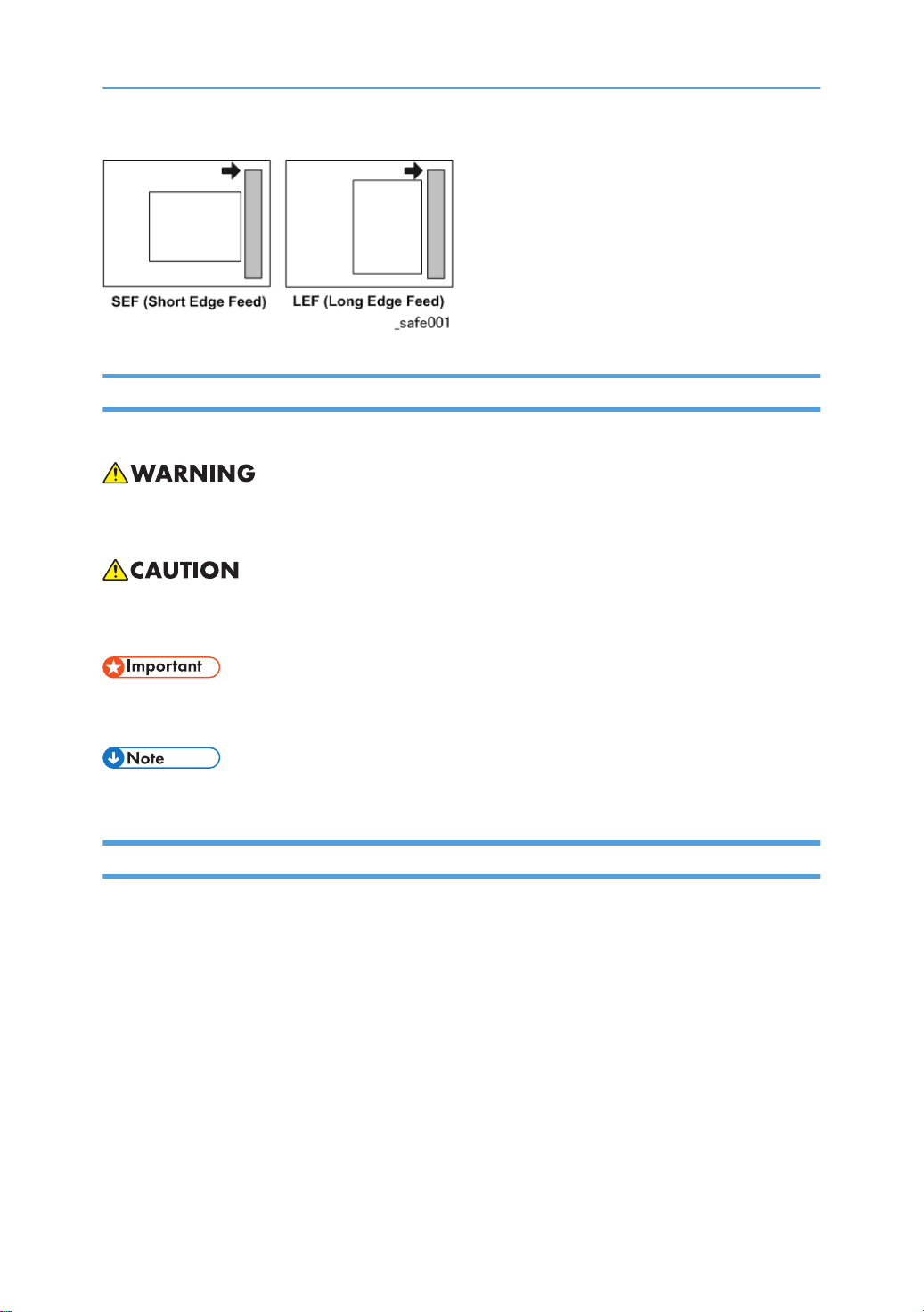
LEF Long Edge Feed
SEF Short Edge Feed
TE Trailing Edge of paper
1
Page 4
Warnings, Cautions, Notes
In this manual, the following important symbols and notations are used.
• A Warning indicates a potentially hazardous situation. Failure to obey a Warning could result in
death or serious injury.
• A Caution indicates a potentially hazardous situation. Failure to obey a Caution could result in
minor or moderate injury or damage to the finisher or other property.
• Obey these guidelines to avoid problems such as misfeeds, damage to originals, loss of valuable
data and to prevent damage to the machine.
• This information provides tips and advice about how to best service the machine.
General Safety Instructions
For your safety, please read this manual carefully before you use this product. Keep this manual handy
for future reference.
Safety Information
Always obey the following safety precautions when using this product.
Safety During Operation
In this manual, the following important symbols and notations are used.
Switches and Symbols
Where symbols are used on or near switches on machines for Europe and other areas, the meaning of
each symbol conforms with IEC60417.
2
Page 5

Responsibilities of the Customer Engineer
Reference Material for Maintenance
• Maintenance shall be done using the special tools and procedures prescribed for maintenance of
the machine described in the reference materials (service manuals, technical bulletins, operating
instructions, and safety guidelines for customer engineers).
•
In regard to other safety issues not described in this document, all customer engineers shall strictly
obey procedures and recommendations described the “CE Safety Guide”.
• Use only consumable supplies and replacement parts designed for use of the machine.
Before Installation, Maintenance
Power
• Always disconnect the power plug before doing any maintenance procedure. After switching off
the machine, power is still supplied to the main machine and other devices. To prevent electrical
shock, switch the machine off, wait for a few seconds, then unplug the machine from the power
source.
•
Before you do any checks or adjustments after turning the machine off, work carefully to avoid
injury. After removing covers or opening the machine to do checks or adjustments, never touch
electrical components or moving parts (gears, timing belts, etc.).
• After turning the machine on with any cover removed, keep your hands away from electrical
components and moving parts. Never touch the cover of the fusing unit, gears, timing belts, etc.
3
Page 6

Installation, Disassembly, and Adjustments
• After installation, maintenance, or adjustment, always check the operation of the machine to make
sure that it is operating normally. This ensures that all shipping materials, protective materials, wires
and tags, metal brackets, etc., removed for installation, have been removed and that no tools
remain inside the machine. This also ensures that all release interlock switches have been restored
to normal operation.
Never use your fingers to check moving parts causing spurious noise. Never use your fingers to
•
lubricate moving parts while the machine is operating.
Special Tools
• Use only standard tools approved for machine maintenance.
For special adjustments, use only the special tools and lubricants described in the service manual.
•
Using tools incorrectly, or using tools that could damage parts, could damage the machine or
cause injuries.
During Maintenance
General
Safety Devices
4
• Before you begin a maintenance procedure: 1) Switch the machine off, 2) Disconnect the power
plug from the power source, 3) Allow the machine to cool for at least 10 minutes.
Avoid touching the components inside the machine that are labeled as hot surfaces.
•
• Never remove any safety device unless it requires replacement. Always replace safety devices
immediately.
Never do any procedure that defeats the function of any safety device. Modification or removal of
•
a safety device (fuse, switch, etc.) could lead to a fire and personal injury. Always test the
operation of the machine to ensure that it is operating normally and safely after removal and
replacement of any safety device.
Page 7

• For replacements use only the correct fuses or circuit breakers rated for use with the machine. Using
replacement devices not designed for use with the machine could lead to a fire and personal
injuries.
Organic Cleaners
• During preventive maintenance, never use any organic cleaners (alcohol, etc.) other than those
described in the service manual.
Make sure the room is well ventilated before using any organic cleaner. Use organic solvents in
•
small amounts to avoid breathing the fumes and becoming nauseous.
• Switch the machine off, unplug it, and allow it to cool before doing preventive maintenance. To
avoid fire or explosion, never use an organic cleaner near any part that generates heat.
• Wash your hands thoroughly after cleaning parts with an organic cleaner to contamination of
food, drinks, etc. which could cause illness.
• Clean the floor completely after accidental spillage of silicone oil or other materials to prevent
slippery surfaces that could cause accidents leading to hand or leg injuries. Use “My Ace” Silicone
Oil Remover (or dry rags) to soak up spills. For more details, please refer to Technical Bulletin
“Silicone Oil Removal” (A024-50).
Ozone Filters
• Always replace ozone filters as soon as their service life expires (as described in the service
manual).
An excessive amount of ozone can build up around machines that use ozone filters if they are not
•
replaced at the prescribed time. Excessive ozone could cause personnel working around the
machine to feel unwell.
Power Plug and Power Cord
• Before servicing the machine (especially when responding to a service call), always make sure that
the power plug has been inserted completely into the power source. A partially inserted plug could
lead to heat generation (due to a power surge caused by high resistance) and cause a fire or other
problems.
Always check the power plug and make sure that it is free of dust and lint. Clean it if necessary. A
•
dirty plug can generate heat which could cause a fire.
5
Page 8
• Inspect the length of the power cord for cuts or other damage. Replace the power cord if
necessary. A frayed or otherwise damaged power cord can cause a short circuit which could lead
to a fire or personal injury from electrical shock.
Check the length of the power cord between the machine and power supply. Make sure the power
•
cord is not coiled or wrapped around any object such as a table leg. Coiling the power cord can
cause excessive heat to build up and could cause a fire.
• Make sure that the area around the power source is free of obstacles so the power cord can be
removed quickly in case of an emergency.
• Make sure that the power cord is grounded (earthed) at the power source with the ground wire on
the plug.
• Connect the power cord directly into the power source. Never use an extension cord.
• When you disconnect the power plug from the power source, always pull on the plug, not the
cable.
After Installation, Servicing
Disposal of Used Items
• Always dispose of used items (developer, toner, toner cartridges, OPC drums, etc.) in accordance
with the local laws and regulations regarding the disposal of such items.
To protect the environment, never dispose of this product or any kind of waste from consumables at
•
a household waste collection point. Dispose of these items at one of our dealers or at an
authorized collection site.
Points to Confirm with Operators
At the end of installation or a service call, instruct the user about use of the machine. Emphasize the
following points.
Show operators how to remove jammed paper and troubleshoot other minor problems by
•
following the procedures described in the operating instructions.
• Point out the parts inside the machine that they should never touch or attempt to remove.
• Confirm that operators know how to store and dispose of consumables.
• Make sure that all operators have access to an operating instruction manual for the machine.
• Confirm that operators have read and understand all the safety instructions described in the
operating instructions.
6
Page 9

• Demonstrate how to turn off the power and disconnect the power plug (by pulling the plug, not the
cord) if any of the following events occur: 1) something has spilled into the product, 2) service or
repair of the product is necessary, 3) the product cover has been damaged.
Caution operators about removing paper fasteners around the machine. They should never allow
•
paper clips, staples, or any other small metallic objects to fall into the machine.
Safety Instructions for this Machine
1. The installation must be done by trained service technicians.
This machine weighs 92 kg. (202.9 lb.). At least four persons are required to remove the machine
2.
from its pallet and position it for installation.
3. To prevent fire hazards never use flammable solvents around the machine.
4. Never place any object on the machine.
5. If anything falls into the machine, turn off the main power switch on the right side of the machine,
then disconnect the power cord from the power source.
6. Locate the machine on a sturdy flat surface where it will not be exposed to excessive vibration.
7. To avoid fire hazard, confirm that the ventilation ports are not blocked, so air can flow freely.
8. Gas generated by the molten glue can irritate the eyes, throat, and nose. The machine should
always be used in a well ventilated room.
9. To avoid the dangers of fire and electrical shock, make sure that the machine is never exposed to:
• Excessive high temperatures and/or humidity
• Dust
• Water
• Direct sunlight
• Open flame
• Corrosive gases
Trademarks
• Microsoft®, Windows®, and MS-DOS® are registered trademarks of Microsoft Corporation in
the United States and /or other countries.
PostScript® is a registered trademark of Adobe Systems, Incorporated.
•
• PCL® is a registered trademark of Hewlett-Packard Company.
• Ethernet® is a registered trademark of Xerox Corporation.
• PowerPC® is a registered trademark of International Business Machines Corporation.
7
Page 10

• Other product names used herein are for identification purposes only and may be trademarks of
their respective companies. We disclaim any and all rights involved with those marks.
8
Page 11

TABLE OF CONTENTS
Safety, Conventions, Trademarks......................................................................................................................1
Conventions.................................................................................................................................................... 1
Common Terms...................................................................................................................................... 1
Warnings, Cautions, Notes...........................................................................................................................2
General Safety Instructions............................................................................................................................2
Responsibilities of the Customer Engineer.................................................................................................... 3
Reference Material for Maintenance...................................................................................................3
Before Installation, Maintenance..................................................................................................................3
Power......................................................................................................................................................3
Installation, Disassembly, and Adjustments.........................................................................................4
Special Tools..........................................................................................................................................4
During Maintenance...................................................................................................................................... 4
General.................................................................................................................................................. 4
Safety Devices........................................................................................................................................4
Organic Cleaners..................................................................................................................................5
Ozone Filters..........................................................................................................................................5
Power Plug and Power Cord................................................................................................................ 5
After Installation, Servicing............................................................................................................................6
Disposal of Used Items..........................................................................................................................6
Points to Confirm with Operators......................................................................................................... 6
Safety Instructions for this Machine...............................................................................................................7
Trademarks.............................................................................................................................................7
1. Replacement and Adjustment
Covers and Trays ............................................................................................................................................ 11
Sensors..............................................................................................................................................................12
Tray sensor, Tray overflow sensor, Vertical transport sensor...................................................................12
Main Motor and Control Board..................................................................................................................... 13
Main Motor..................................................................................................................................................13
Control Board...............................................................................................................................................13
2. Details
Overview.......................................................................................................................................................... 15
General Specifications................................................................................................................................ 15
Overview Layout..........................................................................................................................................16
9
Page 12

Drive Layout..................................................................................................................................................17
Electrical Components.................................................................................................................................
Mechanisms......................................................................................................................................................20
Basic Operation...........................................................................................................................................20
Paper Tray Full Detection............................................................................................................................ 21
Jam Detection...............................................................................................................................................23
18
10
Page 13

1. Replacement and Adjustment
Covers and Trays
1. Trays [A]
Grip each tray by the front and lift out.
2. Front cover [B] ( x 2)
3. Rear cover [C] ( x 3)
4. Top cover [D]
11
Page 14

1. Replacement and Adjustment
Sensors
Tray sensor, Tray overflow sensor, Vertical transport sensor
1. Switch the machine off and unplug the machine
Remove the tray.
2.
3. Bin cover [A]
12
4. Tray sensor ( x 1) [B]
Tray overflow sensor (
5.
Vertical transport sensor (
6.
Raise the pawl, then grip the bottom of the sensor to remove.
x 1) [C]
x 1) [D]
Page 15

Main Motor and Control Board
Main Motor
1. Rear cover page 11
Disconnect the harness of the main motor bracket. (
2.
x 2)
Main Motor and Control Board
3. Main motor bracket [A] ( x 3, timing belt x 1)
4. Main motor [A] ( x 2)
Control Board
1. Rear cover page 11
2.
Bracket [A] (
x4)
13
Page 16

1. Replacement and Adjustment
3. Control board ( x2, x15)
14
Page 17

2. Details
Overview
General Specifications
Number of Bins 9 bins
Paper Size A5. A4, A3
5
" x 8
1/2
Paper Weight 60 to 128g/m²
14 lb – 34 lb Bond
Dimensions (w x d x h) 540 x 600 x 660 mm (21.3 x 23.6 x 26 in.)
Weight Less than 15 kg (33 lb.)
1/2
", 8
" x11", 8
1/2
" x14", 11"x17"
1/2
Power Consumption Less than 48 W
Noise Less than 74 dB
Stack Capacity 100 sheets (each bin)
Power Source DC24V, 5V from main machine
Dimensions (w x d x h) 540 x 600 x 660 mm (21.3 x 23.6 x 26 in.)
Weight Less than 15 kg (33 lb.)
15
Page 18

2. Details
Overview Layout
16
No. Part
1 Exit Roller
2 Transport Roller
3 Junction Gate
4 1 Bin Tray
5 5 Bin Tray
6 9 Bin Tray
Page 19

Drive Layout
Overview
No. Part
1 Drive Belt
2 Driven Belt
3 Transport Motor
17
Page 20

2. Details
Electrical Components
18
No. Name Function
1 Main Motor Drives all the rollers in the unit
2 Tray Sensor (tray 1) to(Tray 9) Detects paper in tray 1 to 9
3 Vertical Transport Sensor 1 Detects misfeeds (located between trays 1 and 2)
4 Vertical Transport Sensor 2 Detects misfeeds (located between trays 3 and 4)
5 Vertical Transport Sensor 3 Detects misfeeds (located between trays 5 and 6)
6 Vertical Transport Sensor 4 Detects misfeeds (located between trays 7 and 8)
7 Vertical Transport Sensor 5 Detects misfeeds (located at the exit to tray 9)
Page 21

No. Name Function
Overview
8 Junction Gate Solenoid 1
Opens/closes the junction gate at the entrance to the
mailbox
9 Junction Gate Solenoids 2-9 Opens/closes the junction gates for trays 1-8.
10 Paper Tray Full Sensor 1 Detects paper full in tray 1.
11 Paper Tray Full Sensor 2-9 Detects paper full in trays 2 to 9. (cannot detect A5)
12 Controller Board Controls the unit.
19
Page 22

2. Details
Mechanisms
Basic Operation
This 9-pin mailbox connects electrically to the finisher with a 14-pin drawer connector. When a print job
starts, the main motor drives to rotate all rollers, and the specified bin receives the paper.
No. Part
1 9 Bin Tray
2 Exit Roller
3 Transport Roller
When the junction gate solenoid turns on, the gate switches and the tray receives the paper. When the
uppermost tray is selected, all solenoids stay off. When the last paper's trailing edge passes the overflow
sensor and the sensor turns off, the paper has gone to the tray, so the selected tray's junction gate
solenoid and the main motor turn off. Normally, the speed of paper transport in this unit is nearly the
same as in the finisher.
20
Page 23

No. Part
1 Junction Gate
Mechanisms
2 Junction Gate Solenoid
Paper Tray Full Detection
Each bin has a tray full sensor 1 (paper overflow sensor) that monitors each tray so it does not become
overloaded.
21
Page 24

2. Details
Paper Tray Full Detection Timing
When output from the paper overflow sensor is more than (T) seconds at the "High" level, full detection
will occur.
For example, at the lowest PPM (12 sheets / A3), when the sensor doesn't switch to "Low" by 40 sec
after the detection, the print job will be stopped.
The machine determines the following depending on the result of the detection and the machine state.
22
Page 25

Status Machine State Trigger
Output 8 sheets of paper in a
Full While receiving paper
row in the same tray while the
paper overflow sensor remains
ON.
Mechanisms
In all states other than receiving paper (with door
closed, no jam, and no remaining paper)
Not Full - The sensor turns OFF
The sensor stays on for more
than 1.5 sec.
Jam Detection
Jam is detected with the five sensors in the picture below;
23
Page 26

2. Details
24
No. Part
1 Finisher Exit Roller
2 Entrance Junction Gate (CS4010)
3 Vertical Transport Sensor
4 Vertical Transport Sensor 2
5 Vertical Transport Sensor 3
6 Vertical Transport Sensor 4
Page 27

No. Part
7 Vertical Transport Sensor 5
8 Open/Close Guide Plate
Jam Detection Details
Jam Name Detection Trigger Log Code
Even though paper moves "pulse x 1.5" (“distance
Transport Sensor 1 Late Jam
L”) from the finisher exit roller, the vertical transport
350
sensor 1 in the 9-bin mailbox doesn’t turn ON.
Transport Sensor 1 Lag Jam (No Change) 351
Transport Sensor 2 Late Jam (No Change) 352
Transport Sensor 2 Lag Jam (No Change) 353
Transport Sensor 3 Late Jam (No Change) 354
Mechanisms
Transport Sensor 3 Lag Jam (No Change) 355
Transport Sensor 4 Late Jam (No Change) 356
Transport Sensor 4 Lag Jam (No Change) 357
Transport Sensor 5 Late Jam (No Change) 358
Transport Sensor 5 Lag Jam (No Change) 359
Cannot continue to receive paper because the
Main Machine Ordering DataWrong Jam
ordering data from the main machine is wrong or
rebooting is demanded because paper reception
360
is unavailable.
25
Page 28

MEMO
26
Page 29

MEMO
27
Page 30

MEMO
28 EN
 Loading...