

Page 1

FOUR-BIN MAILBOX
(Machine Code: G518)
Page 2

1 October, 1999 SPECIFICATIONS
1 OVERALL MACHINE INFORMATION
1.1 SPECIFICATIONS
Number of Trays 4
Tray Capacity: 125 sheets (80 g/m2, 20 lb)
Paper Size for Trays: Maximum: A3 or 11" x 17"
Minimum: A5 (LEF) or 11" x 8
Executive SEF (7.25” x 10.5") can be used
Paper Weight: 60 ~ 105 g/m2, 16 ~ 28 lb
Power Consumption: 17 W or less (average)
Power Source: DC 24 V, 5 V (from the printer)
1/2
"
Dimensions (W x D x H)
Weight:
440 x 520 x 370 mm (17.3 x 20.5 x 14.6")
7 kg, 15.4 lb
G518-1
Options
Page 3
COMPONENT LAYOUT 1 October, 1999
1.2 COMPONENT LAYOUT
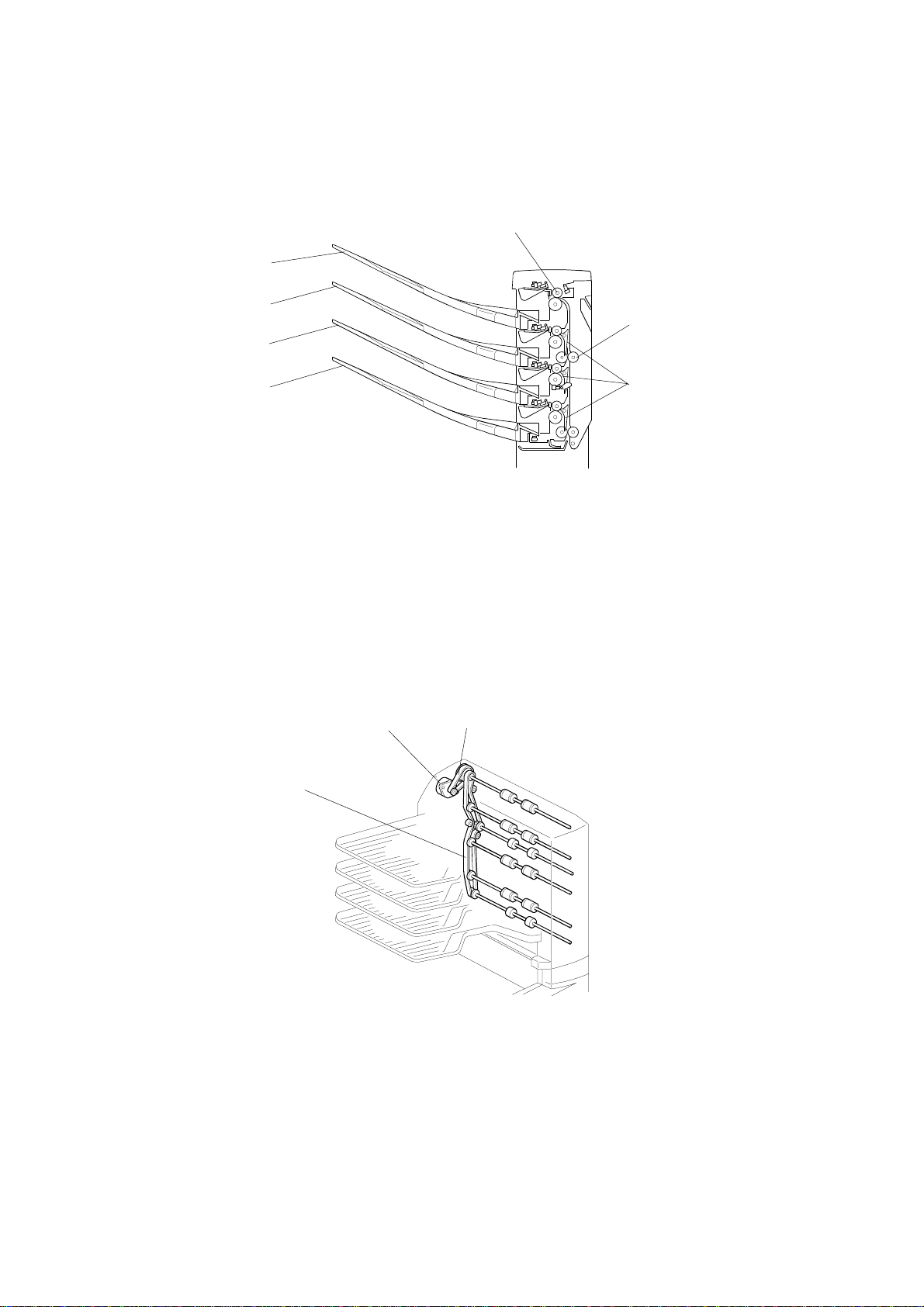
1.2.1 MECHANICAL COMPONENT LAYOUT
7
1
2
6
3
4
1. 4th Tray
2. 3rd Tray
3. 2nd Tray
4. 1st Tray
1.2.2 DRIVE LAYOUT
1
5
G518D101.WMF
5. Turn Gate
6. Vertical Transport Roller
7. Tray Feed Out Roller
3
2
1. Timing Belt
2. Main Motor
3. Main Motor Timing Belt
G518D103.WMF
G518-2
Page 4
1 October, 1999 ELECTRICAL COMPONENT DESCRIPTIONS
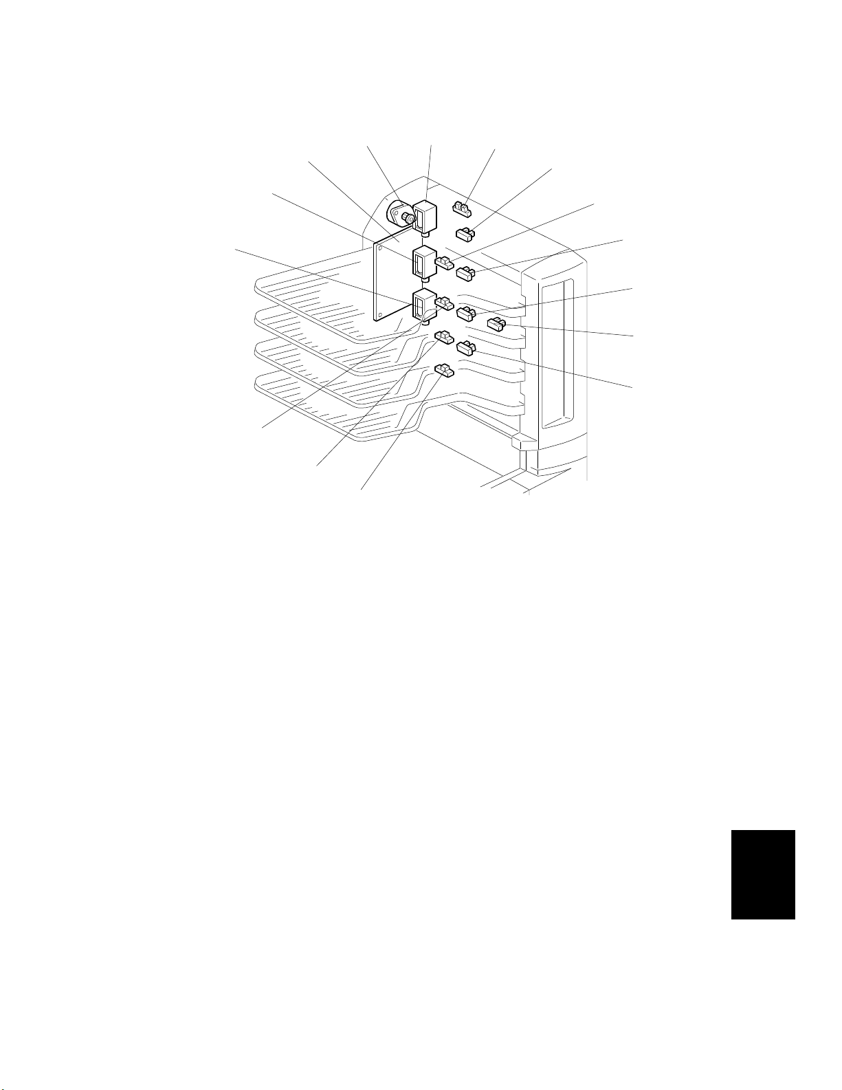
1.3 ELECTRICAL COMPONENT DESCRIPTIONS
14
15
13
1
12
11
2
3
4
5
6
7
8
9
10
G518D102.WMF
See the next page for the component description table.
Options
G518-3
Page 5

ELECTRICAL COMPONENT DESCRIPTIONS 1 October, 1999
Symbols Name Function Index No.
Motors
M1 Main Drives all the mailbox rollers. 2
Sensors
S1 Tray 4 Paper Detects if there is paper in the 4th tray. 6
S2 Tray 3 Paper Detects if there is paper in the 3rd tray. 13
S3 Vertical
Transport
Detects misfeeds (between the 1st and
2nd trays)
9
S4 Tray 2 Paper Detects if there is paper in the 2nd tray. 12
S5 Tray 1 Paper Detects if there is paper in the 1st tray. 11
S6 Tray 1 Paper
Detects paper overflow in the 1st tray. 10
Overflow
S7
Tray 2 Paper
Detects paper overflow in the 2nd tray. 8
Overflow
S8 Tray 3 Paper
Detects paper overflow in the 3rd Tray. 7
Overflow
S9 Tray 4 Paper
Detects paper overflow in the 4th tray. 5
Overflow
Solenoids
SOL1 Turn Gate
Solenoid 1
SOL2
Turn Gate
Solenoid 2
SOL3 Turn Gate
Solenoid 3
Opens and closes the junction gate to
direct paper into the 1st tray.
Opens and closes the junction gate to
direct paper into the 2nd tray.
Opens and closes the junction gate to
direct paper into the 3rd tray gate.
PCBs
PCB1 Main Control Controls all mailbox functions 1
Switches
SW1 Door Safety
Cuts the dc power line when the transport
cover is opened.
14
15
3
4
G518-4
Page 6

1 October, 1999 BASIC OPERATION
2. DETAILED DESCRIPTIONS
2.1 BASIC OPERATION
[A]
[B]
G518D104.WMF
G518D105.WMF
The mailbox is connected to the main unit by a 10-pin connector.
When the leading edge of the paper acti vates the exit sensor on the interchange
unit, the mailbox main motor turns on and the mailbox rollers begin to turn. The
paper is then fed out to the tray that has been selected.
Solenoids [B] open and close junction gates as shown, to direct the paper to the
selected tray. When the top tray (tray 4) is selected, none of the solenoids are
activated. As the last sheet is fed out, it turns off the vertical transport sensor, and
both the mailbox motor and the junction gate solenoid of the selected bin turn off.
The mailbox normally feeds paper at 121 mm/s. For the G038 printer, this is about
equal to the speed of the printer itself (actual transport speeds are: 121.6 mm/s
and 120.6 mm/s, respectively) .
G518-5
Options
Page 7

PAPER OVERFLOW DETECTION 1 October, 1999
2.2 PAPER OVERFLOW DETECTION
2.2.1 OVERVIEW
The overflow sensors are installed on each tray. They monitor the trays so that the
amount of paper present does not exceed the tray capacity. If a printing job is done
that exceeds the capacity of one or more of the trays, the main unit recognizes the
overload, displays an error message and stops the printing job. However, if the
excess paper is removed from the overloaded tray, the printing job will continue.
2.2.2 DETECTION TIMING
Between Sheets
T
Full
Not Full
(H)
(L)
Paper
Length
Paper
Length
Paper
Length
Full
G518D107.WMF
When the sensor output is high for longer than T (calculated by the equation
below), the machine determines that the tray is full.
The detection timing for a full tray is calculated by the equation below for each
paper size. For example, with a minimum ppm of 12 prints (for A3), the value of T
would be 15 seconds. Therefore, if the sensor continuously detects paper for 15 or
more seconds (as it would if the tray were actually full and a given sheet of paper
was stopped at the sensor), the machine stops the copy job, assuming that the tray
is full. The value of T will be different for each pap er size, since the value of ppm
will vary with size.
T (seconds) = (60/min. PPM) x 3 * PPM = prints per minute.
G518-6
Page 8

1 October, 1999 PAPER MISFEED DETECTION TIMING
2.3 PAPER MISFEED DETECTION TIMING
A4 sideways (longedge) paper to exit to the 1st bin tray
Main Motor
(Main frame)
J1
Exit Sensor
(Interchange Unit)
Main Motor
(Mailbox)
Turn Gate
Solenoid *1
*1: Time required for A4 longedge paper
*1
A4 sideways (longedge) paper to exit to the 2nd, 3rd, or 4th tray
Main Motor
(Main frame)
J1
Exit Sensor
(Interchange Unit)
Main Motor
(Mailbox)
Turn Gate
Solenoid *2
Vertical Transport
Sensor
*1: Time required for A4 longedge paper
*2: All solenoids stay off for feed to the 4th tray.
*1
J2
J3
*1
G518D108.WMF
Options
G518-7
Page 9

PAPER MISFEED DETECTION TIMING 1 October, 1999
J1 Timing:
J2 Timing:
J3 Timing:
After the leading edge of the paper activates the exit sensor of the
interchange unit, a misfeed is detected if this sensor does not turn off
within X + 0.52 s, where X is equal to the amount of time a given paper
size takes to pass the sensor (e.g. A4 - sideways = 1.74 s).
After the paper exit sensor of the interchange unit is activated, the
machine determines that the paper has not yet fed and detects a misfeed
if the vertical transport sensor does not activate within 1.94 s (in the case
of A4 paper).
After the vertical transport sensor is activated, a misfeed is detected if
this sensor does not turn off within X + 0.52 s (see above for an
explanation of X). For example, this value would be 2.26 s for A4
sideways.
G518-8
Page 10

1 October, 1999 EXTERIOR COVER REMOVAL
3. REPLACEMENT AND ADJUSTMENT
3.1 EXTERIOR COVER REMOVAL
[C]
[D]
[B]
[A]
G518R101.WMF
1. Turn the main switch off and remove the power cord from the outlet.
2. Take out each tray [A] (lift by the edges).
3. Remove the front cover [B] (1 screw).
4. Remove the rear cover [C] (1 screw).
5. Remove the upper cover [D].
G518-9
Options
Page 11

OVERFLOW AND VERTICAL TRANSPORT SENSOR 1 October, 1999
3.2 OVERFLOW AND VERTICAL TRANSPORT SENSOR
[A]
G518R103.WMF
[B]
[C]
1. Turn the main switch off and unplug the power cord.
2. Remove each tray.
3. Remove the bin covers [A].
4. Remove the connector of the tray sensor [B].
Remove the connector of the overflow sensor [C]
Remove the connector of the vertical transport sensor [D].
[D]
G518R104.WMF
5. Remove both the tray and overflow sensors as shown in the illustration.
For the vertical transport sensor, lift up the locking pawls (slightly).
Remove the sensor by rotating the bottom part upward.
G518-10
Page 12

1 October, 1999 MAIN MOTOR REPLACEMENT
3.3 MAIN MOTOR REPLACEMENT
[B]
[C]
[D]
[A]
G518R102.WMF
1. Turn the main switch off and unplug the power cord.
2. Remove the rear cover.
3. Remove the control board [A] (2 screws, all connectors).
4. Remove the timing belt [B] (2 screws) and the main motor bracket [C].
5. Replace the main motor (2 screws) [D].
G518-11
Options
 Loading...