

Page 1

FOUR-BIN MAILBOX
(Machine Code: G696)
Page 2

20 March 1998 SPECIFICATIONS
1. OVERALL MACHINE INFORMATION
1.1 SPECIFICATIONS
Number of Trays 4
2
Tray Capacity: 125 sheets (80 g/m
, 20lb)
Paper Size for Trays:
Maximum: A3 or 11" x 17"
Minimum: A5 (LEF) or 11" x 8
1/2
"
Executive SEF (7.25" x 10.5") can be used
Paper Weight: 60 ~ 90 g/m
2
, 16 ~ 24 lb
Power Consumption: 20 W or less (average)
Power Source: DC24 V, 5 V (from the printer)
Dimensions (W x D x H): 465 x 490 x 370 mm (18.3" x 19.3" x 14.6")
Weight: 7 kg , 15.4 lb
•
Specifications are subject t o change without notice.
G696-1
Options
Page 3
COMPONENT LAYOUT 20 March 1998
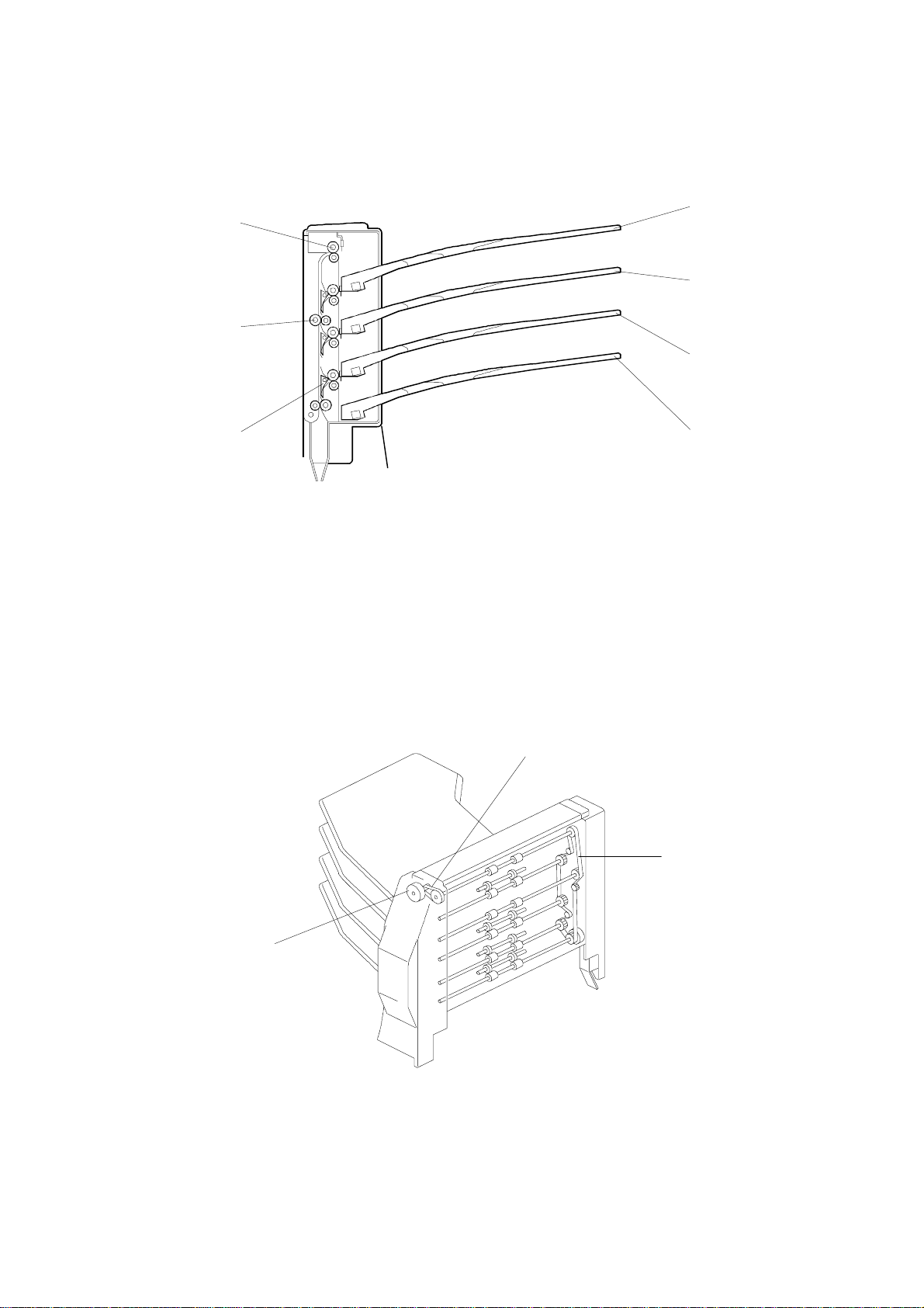
1.2 COMPONENT LAYOUT
1.2.1 MECHANICAL COMPONENT LAYOUT
1
7
2
6
3
5
1. 5th Tray
2. 4th Tray
3. 3rd Tray
4. 2nd Tray
1.2.2 DRIVE LAYOUT
4
G696V500.WMF
5. Turn Gate
6. Vertical Transport Roller
7. Tray Feed Out Roller
3
1
1. Timing Belt
2. Main Mot o r
2
G696V501.WMF
3. Main Mot o r Timing Belt
G696-2
Page 4
20 March 1998 ELECTRICAL COMPONENT DESCRIPTIONS
1.3 ELECTRICAL COMPONENT DESCRIPTIONS
Refer to the electrical component layout and the point-to-point diagram on the
waterproof paper in the pocket for symbols and index numbers.
Symbols Name Function Index No.
Motors
M1 Main Drives all the mailbox rollers. 12
Sensors
S1 Tray 5 Paper Detects if there is paper in the 5th tray. 2
S2 Tray 4 Paper Detects if there is paper in the 4th tray. 3
S3 Upper Transport Detects misfeeds. 4
S4 Tray 3 Paper Detects if there is paper in the 3rd tray. 5
S5
S6 Tray 2 Paper Detects if there is paper in the 2nd tray. 7
Solenoids
SOL1 2nd Tray Opens and closes the 2nd tray gate. 8
SOL2
SOL3 3rd Tray Opens and closes the 3rd tray gate. 11
SOL4 4th Tray Opens and closes the 4th tray gate. 13
Lower Transport Detects misfeeds, and controls the 3rd
and 4th tray solenoid on/off timing.
Turn Gate Opens and closes the turn gate to direct
paper into either the 1st tray (the base
machine’s output tray) or to the mailbox.
6
9
PCBs
PCB1 Main Control Controls all sorter functions 10
Switches
SW1
Door Safety
Cuts the dc power line when the transport
cover is opened.
1
Options
G696-3
Page 5
BASIC OPERATION 20 March 1998
2. DETAILED DESCRIPTIONS
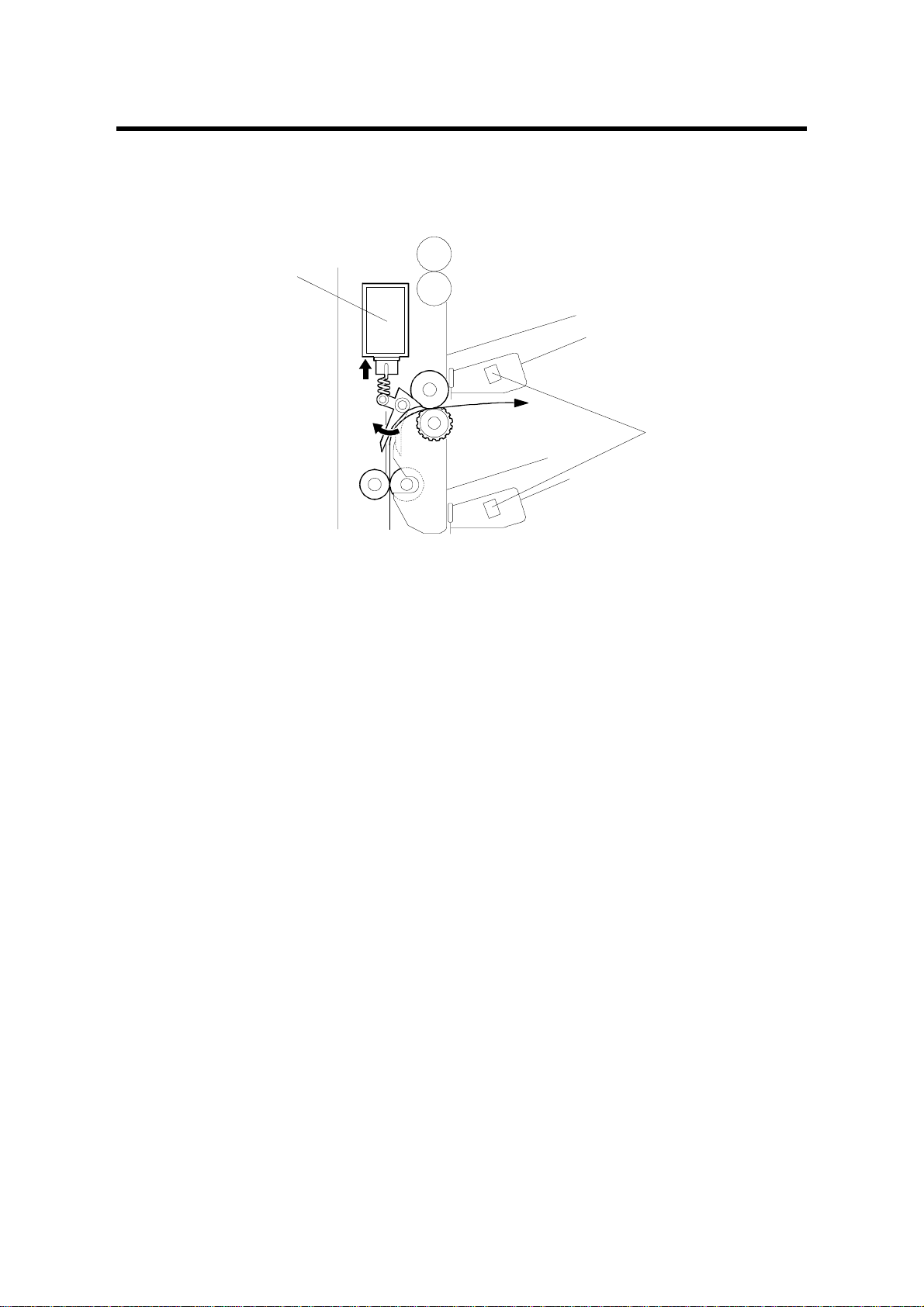
2.1 BASIC OPERATION
[A]
[B]
G696D504.WMF
The four-bin mailbox is electrically connected to the base printer by an eight-pin
connector. One of these pins acts as a connection det ection mechanism.
Feed
When the mailbox is selected as the output tray and the lower exit sens or of the
base printer is actuated by the leading edge of the paper, the mailbox main motor
turns on, turning the transport rollers.
Soon after the main motor starts, t he turn gate solenoid energizes to direct the
paper to the four-bin mailbox. (If the standard output tray is selected, the turn gate
solenoid does not energize.) Then the selected tray solenoid [A] energizes, to
direct the paper to that tray. (If the 5th tray is selected, no solenoid turns on.)
When the last printout passes the transport s ensor and feeds out, the t ray sol enoi d
and the main motor turn off.
Normally, the paper transport speed is 180 mm/s. This speed is reduced to 114
mm/s when a large paper size is used (such as DLT or A3), to synchronize feed
speed with the fusing unit while part of the paper is still left in the fusing unit.
G696-4
Page 6

20 March 1998 BASIC OPERATION
Jam Detection
Two transport sensors, lower and upper, detect misfeeds within the unit. When the
2nd or 3rd tray is selected, the lower transport sensor (located just before the feedout section of the 2nd tray) monitors misfeeds. When the 4th or 5th tray is selected,
both sensors monitor misfeeds. Only the lower transport sensor is used to control
the on/off timing of the tray solenoids for prin ts that are fed out to the 3rd and 4th
trays. (For details, refer to the timing charts.)
Paper Sensors
Each tray has a paper sensor [B] to detect paper i n the t r ay. E ach tray is monitored
to ensure that the tray does not contain more than 125 prints. If a print job of more
than 125 sheets is executed, the base printer will do up to 125 prints, then an error
message will appear in the printer display panel and the printing job is stopped.
Once the output stack is removed, the printing job automatically continues.
G696-5
Options
Page 7

TIMING CHART AND MISFEED DETECTION 20 March 1998
2.2 TIMING CHART AND MISFEED DETECTION
2ND TRAY
Mailbox ON/OFF
Interface
Paper Feed-out
Signal (Printer)
Lower Transport Sensor
Upper Transport Sensor
Paper Feed-out Signal
(Mailbox)
Main Motor
Turn Gate Sol.
2nd Tray Sol.
3rd Tray Sol.
4th Tray Sol.
0
ON OFF
ON
0.86
0.4
@
12345
0.3
2nd tray feed-out
(1)
@
(2)
(seconds)
G696D500.WMF
NOTE:
1) Print size: LT (LE F )
2) Number of prints: 2
@
(1): Checks whether the lower transport sensor is actuated with i n 4.09 sec onds
after the paper feed-out signal from the printer.
@
(2): Checks whether the paper has passed through the lower transport sensor
2.92 seconds after it has been actuated.
G696-6
Page 8

20 March 1998 TIMING CHART AND MISFEED DETECTION
3RD TRAY
Mailbox ON/OFF
Interface
Paper Feed-out
Signal (Printer)
Lower Transport Sensor
Upper Transport Sensor
Paper Feed-out Signal
(Mailbox)
Main Motor
Turn Gate Sol.
2nd Tray Sol.
3rd Tray Sol.
4th Tray Sol.
0
ON OFF
ON
0.86
@
12345
0.7
3rd tray feed-out
(1)
@
(2)
(seconds)
G696D501.WMF
NOTE:
1) Print size: LT (LE F )
2) Number of prints: 2
@
(1): Checks whether the lower transport sensor is actuated with i n 4.09 sec onds
after the paper feed-out signal from the printer.
@
(2): Checks whether the paper has passed through the lower transport sensor
2.92 seconds after it has been actuated.
Options
G696-7
Page 9

TIMING CHART AND MISFEED DETECTION 20 March 1998
4TH TRAY
Mailbox ON/OFF
Interface
Paper Feed-out
Signal (Printer)
Lower Transport Sensor
Upper Transport Sensor
Paper Feed-out Signal
(Mailbox)
Main Motor
Turn Gate Sol.
2nd Tray Sol.
3rd Tray Sol.
4th Tray Sol.
0
ON OFF
ON
@
12345
0.5
(1)
@
(2)
@
(3)
(4)
@
(seconds)
0.3
4th tray feed-out
G696D502.WMF
NOTE:
1) Print size: LT (LE F )
2) Number of prints: 2
@
(1): Checks whether the lower transport sensor is actuated with i n 4.09 sec onds
after the paper feed-out signal from the printer.
@
(2): Checks whether the upper transport sensor is actuated withi n 1.06 sec onds
after the lower transport sensor is act uated.
@
(3): Checks whether the paper has passed through the lower transport sensor
2.92 seconds after it has been actuated.
@
(4): Checks whether the paper has passed through the upper transport sensor
2.92 seconds after it has been actuated.
G696-8
Page 10

20 March 1998 TIMING CHART AND MISFEED DETECTION
5TH TRAY
Mailbox ON/OFF
Interface
Paper Feed-out
Signal (Printer)
Lower Transport Sensor
Upper Transport Sensor
Paper Feed-out Signal
(Mailbox)
Main Motor
Turn Gate Sol.
2nd Tray Sol.
3rd Tray Sol.
4th Tray Sol.
0
ON OFF
ON
@
12345
(1)
(2)
@
(3)
@
(4)
@
(seconds)
0.7
5th tray feed-out
G696D503.WMF
NOTE:
1) Print size: LT (LE F )
2) Number of prints: 2
@
(1): Checks whether the lower transport sensor is actuated with i n 4.09 sec onds
after the paper feed-out signal from the printer.
@
(2): Checks whether the upper transport sensor is actuated withi n 1.06 sec onds
after the lower transport sensor is act uated.
@
(3): Checks whether the paper has passed through the lower transport sensor
2.92 seconds after it has been actuated.
@
(4): Checks whether the paper has passed through the upper transport sensor
2.92 seconds after it has been actuated.
Options
G696-9
Page 11

MAILBOX REMOVAL 20 March 1998
3. REPLACEMENT AND ADJUSTMENT
3.1 MAILBOX REMOVAL
[B]
[A]
G696R503.WMF
1. Turn off the main switch and unplug the power cord.
2. Remove the two knob screws [A] securing the mailbox [B].
3. Remove the mailbox as shown.
G696-10
Page 12

20 March 1998 EXTERIOR COVER REMOVAL
3.2 EXTERIOR COVER REMOVAL
[C]
[E]
[F]
[A]
[D]
[B]
G696R500.WMF
Tray Removal
1. Remove the trays [A].
Vertical Transport Cover
1. Open the vertical transport cover [B] and remove it (1 screw [C]).
Front/Rear/Top Cover
1. Remove the mailbox. (See Mailbox Removal.)
2. Remove the front cover [D] (1 screw).
3. Remove the rear cover [E] (2 screws).
4. Remove the top cover [F].
Options
G696-11
Page 13

TRAY PAPER SENSOR AND TRANSPORT SENSOR REPLACEMENT 20 March 1998
3.3 TRAY PAPER SENSOR AND TRANSPORT SENSOR
REPLACEMENT
[A]
[B]
[C]
G696R504.WMF
[E]
1. Turn off the main switch and unplug the printer.
2. Remove the mailbox from the printer. (See Mailbox Remo val .)
[F]
[D]
G696R505.WMF
3. Remove the rear cover. (See Exterior Cover Rem oval. )
Tray Paper Sensor
4. Remove the paper sensor cover [A] (3 snap fits).
5. Remove the tray paper sensor bracket [B] (1 sc rew and 1 connector).
6. Replace the tray paper sensor [C] (1 screw).
Transport Sensor
4. Free the tray feed-out cover [D] (1 screw).
5. Replace the transport sensor [E] (1 snap fit and 1 connector).
NOTE:
When reinstalling the tray feed-out cover, make sure that the transport
sensor actuator rests above the verti cal transport roller shaft [F], as shown.
G696-12
Page 14

20 March 1998 TURN GATE SOLENOID REPLACEMENT
3.4 TURN GATE SOLENOID REPLACEMENT
[B]
[C]
[A]
G696R501.WMF
1. Turn off the main switch and unplug the printer.
2. Remove the mailbox from the printer. (See Mailbox Remo val .)
3. Remove the rear cover. (See Exterior Cover Rem oval. )
4. Remove the turn gate solenoid with the bracket [A] (3 screws and 1 connect o r).
NOTE:
Remove the main control board [B] (4 screws and al l th e connect ors) if
the turn gate solenoid bracket can not be removed smoothly.
5. Replace the turn gate solenoid [C] (2 screws).
NOTE:
Make sure the solenoid’s plunger pin is installed in the cutout in the
frame.
Options
G696-13
Page 15

MAIN MOTOR AND TRAY SOLENOID REPLACEMENT 20 March 1998
3.5 MAIN MOTOR AND TRAY SOLENOID RE PLACEMENT
[D]
[B]
[C]
G696R502.WMF
1. Turn off the main switch and unplug the printer.
2. Remove the mailbox from the printer. (See Mailbox Remo val .)
3. Remove the rear cover. (See Exterior Cover Rem oval. )
4. Remove the main control board [A] (4 screws and all the connectors).
Mai n Mo t or
5. Remove the main motor bracket [B] (2 screws and a timing belt).
6. Replace the main motor [C] (2 screws).
Tray Solenoid
5. Replace the desired tray solenoid [D] (2 screws).
NOTE:
Make sure the solenoid’s plunger pin is installed in the cutout in the
frame.
[A]
G696-14
Page 16

4 BIN MAILBOX (G696) ELECTRICAL COMPONENT LAYOUT
12
11
10
13
1
2
3
4
5
6
7
9
Description Index No. P-to-P Location
Door Safety Switch (SW1) 1 D2
Tray 5 Paper Sensor (S1) 2 F2
Tray 4 Paper Sensor (S2) 3 J2
Upper Transport Sensor (S3) 4 K2
Tray 3 Paper Sensor (S4) 5 E2
Lower Transport Sensor (S5) 6 I2
Tray 2 Paper Sensor (S6) 7 H2
2nd Tray Solenoid (SOL1) 8 G16
Turn Gate Solenoid (SOL2) 9 E16
Main Control Board (PCB1) 10 K12
3rd Tray Solenoid (SOL3) 11 H16
Main Motor (M1) 12 B16
4th Tray Solenoid (SOL4) 13 J16
8
G696S500.WMF
Page 17

MAIL BOX (G696) POINT TO POINT DIAGRAM
DATE: September 5th '97
1234567891011121314151617
A
B
C
DOOR SAFETY SW
D
E
TRAY 3
PAPER SENSOR
F
TRAY 5
PAPER SENSOR
G
TRAY 2
PAPER SENSOR
H
LOWER
TRANSPORT
I
SENSOR
TRAY 4
J
PAPER SENSOR
Symbol Table
AC Line
DC Line
Signal Direction
Active High
V
Active Low
W
Voltage
[ ]
S4
S1
S6
S5
S2
(SW1)
COVER SW
GND
5V
3 BIN SEN.
GND1
5V
5 BIN SEN.
GND1
5V
2 BIN SEN.
GND1
GND1
LO SEN.
5V
5V
4 BIN SEN.
GND1
CN210-2
CN210-1
CN220-3
CN220-2
CN220-1
CN230-3
CN230-2
CN230-1
CN240-3
CN240-2
CN240-1
CN250-3
CN250-2
CN250-1
CN260-3
CN260-2
CN260-1
HOST
INTERFACE
CONNECT
TXD
RXD
STOP
GND1
5V
GND2
24V
CN225-1
CN225-3
CN235-1
CN235-3
CN245-1
CN245-3
CN245-4
CN245-6
CN265-1
CN265-3
CN265-4
CN265-6
CN200-1
CN200-2
CN200-3
CN200-4
CN200-5
CN200-6
CN200-7
CN200-8
CN225-3
CN225-2CN225-2
CN225-1
CN235-3
CN235-2CN235-2
CN235-1
CN245-6
CN245-5CN245-2
CN245-4
CN245-3
CN245-2CN245-5
CN245-1
CN265-6
CN265-5CN265-2
CN265-4
CN265-3
CN265-2CN265-5
CN265-1
CONNECT
TXD
RXD
STOP
GND1
5V
GND2
24V
COVER SW
GND1
5V
3 BIN SEN.
GND1
5V
5 BIN SEN.
GND1
2 BIN SEN.
GND1
GND1
LO SEN.
5V
N.C.
5V
4 BIN SEN.
GND1
GND1
UP SEN.
5V
CN100-1
CN100-2
CN100-3
CN100-4
CN100-5
CN100-6
CN100-7
CN100-8
CN150-1
CN150-2
CN150-3
CN150-4
CN150-5
CN150-6
CN150-7
CN150-8
CN160-15V
CN160-2
CN160-3
CN160-4
CN160-5
CN160-6
CN160-7
CN160-8
CN160-9
CN160-10
CN160-11
CN160-12
CN160-13
[W 5]
[VW 5]
[VW 5]
[W 5]
[V 5]
[V 5]
[V 5]
[V 5]
[V 5]
[V 5]
[V 5]
[VW 24]
[VW 24]
[VW 24]
[VW 24]
[W 24]
[W 24]
[W 24]
[W 24]
24V
24V
N.C.
A
/A
B
/B
24V
24V
24V
SOL4
CN120-1
CN120-2
CN120-3
CN120-4
CN120-5
CN120-6
CN120-7
CN130-1
CN130-2SOL1
CN135-1
CN135-2SOL2
CN140-124V
CN160-2SOL3
CN145-1
CN145-2
MAIN MOTOR
M1
SOL2
SOL1
SOL3
SOL4
TURN GATE
SOLENOID
2nd TRAY
SOLENOID
3rd TRAY
SOLENOID
4th TRAY
SOLENOID
A
B
C
D
E
F
G
H
I
J
K
UPPER
TRANSPORT
SENSOR
S3
GND1
UP SEN.
5V
CN270-3
CN270-2
CN270-1
MAIN CONTROL BOARD
PCB1
L
1234567891011121314151617
K
L
 Loading...