

Page 1

SORTER
Page 2

1 February 1994 OVERALL MACHINE INFORMATION
1. OVERALL MACHINE INFORMATION
1.1 SPECIFICATIONS
Paper Size for Bins: Max. 11" x 17"/A3
Min. 51/2" x 81/2"/A5
Paper Size for Interrupt/
Top Bins:
Copy Paper Weight: 14 to 24 lb/52 to 90 g/m
Max. 11" x 17"/A3
Min. 51/2" x 81/2"/A5
2
Number of Bins: 10 bins, 1 interrupt bin and 1 print bin
Bin Capacity: Sort 50 sheets/bin
(20 lb/80 g/m2, one-sided copies)
30 sheets/bin
(20 lb/80 g/m2, duplex copies)
Stack 40 sheets/bin
(20 lb/80 g/m2, one-sided copies)
20 sheets/bin
(20 lb/80 g/m2, duplex copies)
Top Bin Capacity
(Clear Mode):
150 sheets (20 lb/80 g/m2, one-sided copies)
100 sheets (20 lb/80 g/m2, duplex copies)
Printer Bin Capacity: 500 sheets (20 lb/80 g/m2, 81/2" x 11"/A4)
150 sheets (20 lb/80 g/m2, other size)
Interrupt Bin Capacity: 100 sheets (20 lb/80 g/m2)
Power Source: DC 24 V from copier
Power Consumption: 90 W (Max), 30 W (Average)
Dimensions (W x D x H): 19.6" x 21.1" x 23.6"/499 x 535 x 600 mm
Weight: 48.5 lb/22 kg
1
Sorter
Page 3
OVERALL MACHINE INFORMATION 1 February 1994
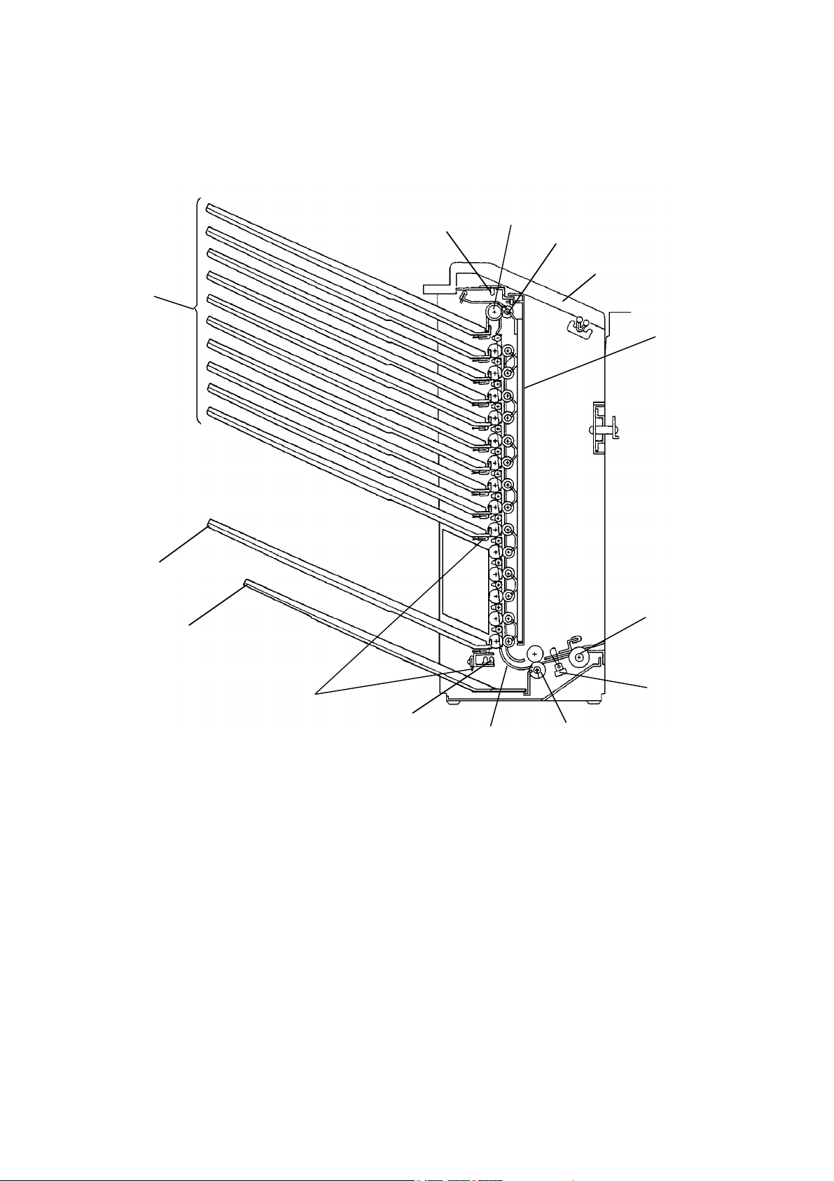
1.2 COMPONENT LAYOUT
1.2.1 Mechanical Components
1
14
2
3
4
5
13
12
11
1. Entry Sensor Photo Transistor
2. Vertical Drive Rollers
3. Pressure Rollers
4. Sorter Cover
5. Vertical Guide Unit
6. Sponge Roller
10
9
8. Turn Gate Roller
9. Turn Gate
10. Entry Sensor LED
11. Discharge Brush
12. Interrupt Bin
13. Printer Bin
6
7
8
7. Inlet Sensor
14. Standard Bins
2
Page 4
5
28 December 1993 OVERALL MACHINE INFORMATION
1.2.2 Electrical Components
18
19
3
4
2
1
6
7
8
9
10
11
12
13
14
17
1. Inlet Sensor
2. Entry Sensor Photo Transistor
3. Sorter Cover Safety Switch 1
4. Sorter Cover Safety Switch 2
5. Entry Sensor LED
6. 2nd Bin Solenoid
7. 3rd Bin Solenoid
8. 4th Bin Solenoid
9. 5th Bin Solenoid
15
16
11. 7th Bin Solenoid
12. 8th Bin Solenoid
13. 9th Bin Solenoid
14. 10th Bin Solenoid
15. Printer Bin Solenoid
16. Interrupt Bin Solenoid
17. Sorter Motor
18. Sorter Main Board
19. Exhaust Fan (A109 copier only)
Sorter
10. 6th Bin Solenoid
3
Page 5

OVERALL MACHINE INFORMATION 28 December 1993
1.3 ELECTRICAL COMPONENT DESCRIPTIONS
Symbol Name Function Index No.
Motors
M1 Sorter Motor Drives all the sorter rollers. 17
M2 Exhaust Fan
(A109 copier only)
Solenoids
SOL1 2nd Bin Solenoid Open and close the 2nd bin gate. 6
SOL2 3rd Bin Solenoid Open and close the 3rd bin gate. 7
SOL3 4th Bin Solenoid Open and close the 4th bin gate. 8
SOL4 5th Bin Solenoid Open and close the 5th bin gate. 9
SOL5 6th Bin Solenoid Open and close the 6th bin gate. 10
SOL6 7th Bin Solenoid Open and close the 7th bin gate. 11
SOL7 8th Bin Solenoid Open and close the 8th bin gate. 12
SOL8 9th Bin Solenoid Open and close the 9th bin gate. 13
SOL9 10th Bin Solenoid Open and close the 10th bin gate. 14
SOL10 Printer Bin Solenoid Open and close the printer bin gate. 15
SOL11 Interrupt Bin Solenoid Open and close the interrupt bin gate. 16
Flow the air out from the copier fusing
exhaust fan.
19
Switches
SW1 Sorter Cover Safety
Switch 1
SW2 Sorter Cover Safety
Switch 2
Sensors
S1 Entry Sensor Detects misfeeds and when the copy
S2 Inlet Sensor Detects misfeeds and when the copy
Printed Circuit Boards
PCB 1 Sorter Main Board Controls all sorter functions. 18
Detects when the sorter cover is opened. 3
Cut the +24 volts power line. 4
paper exits.
paper enters.
2 and 5
1
4
Page 6
1 February 1994 OVERALL MACHINE INFORMATION
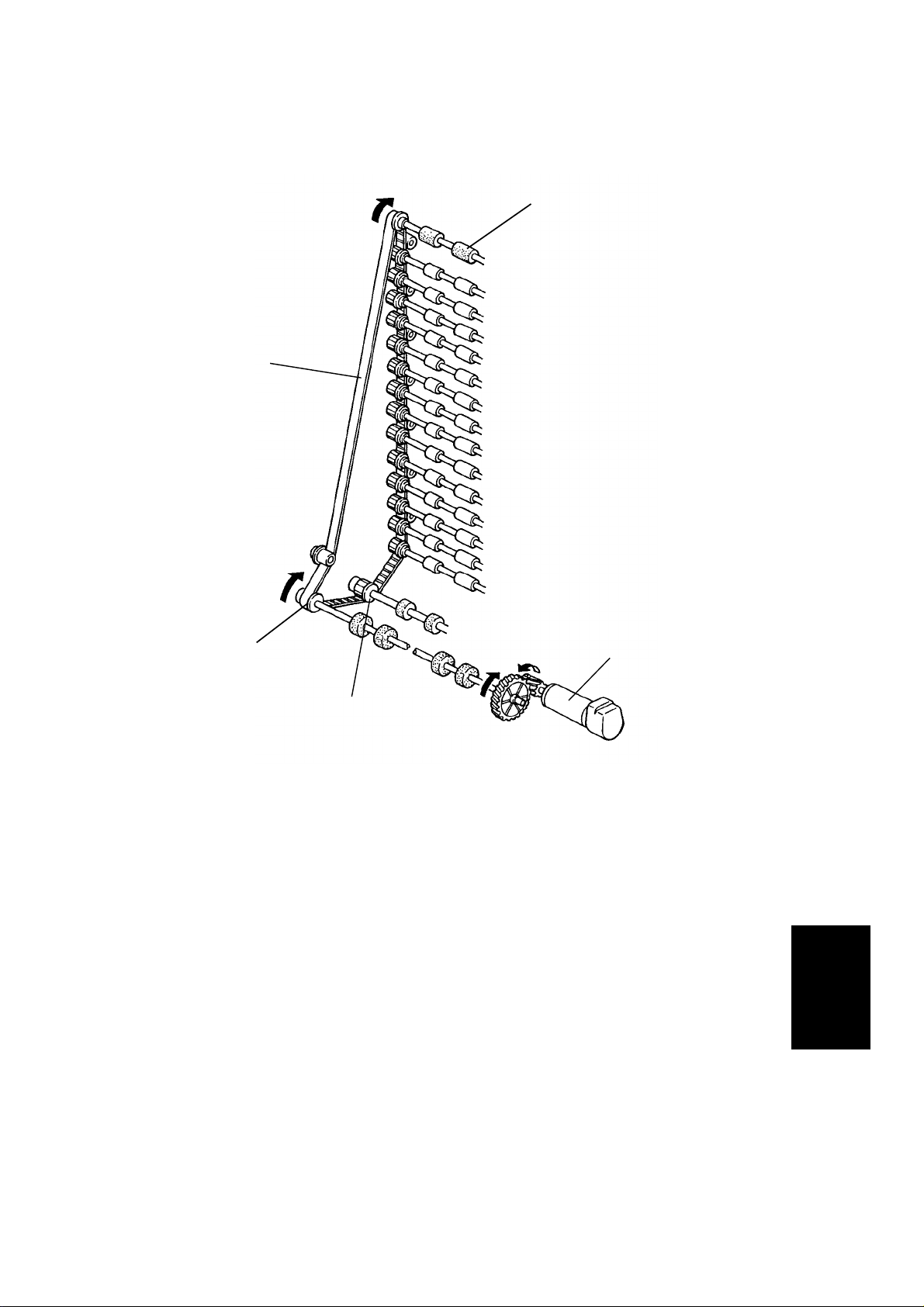
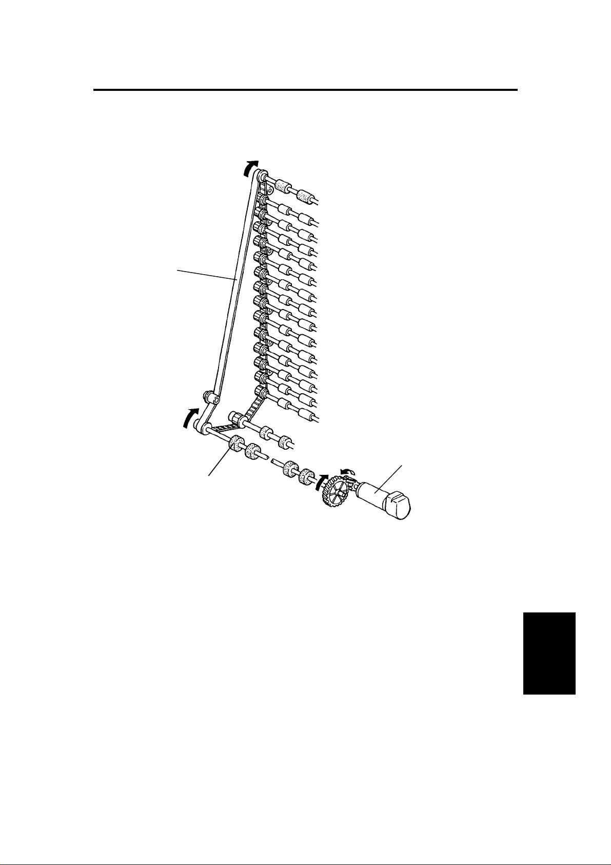
1.4 DRIVE LAYOUT
1
5
4
3
1. Vertical Drive Rollers (10 Rollers)
2. Sorter Motor
3. Turn Gate Roller Pulley
4. Sponge Roller Pulley
5. Timing Belt
2
Sorter
5
Page 7

OVERALL MACHINE INFORMATION 1 February 1994
1.5 BASIC OPERATION
- Introduction -
Sorter operation begins when the copier exit sensor turns on. At that time, the
sorter motor turns on and the rollers start turning.
The sorter has two paper transport speeds. When the sorter motor turns on, it
rotates at slow speed of 220 mm/s. This is the slightly faster than the copier’s
transport speed. When the trailing edge of the paper passes the copier exit
sensor, the sorter shifts to high speed which is about 550 mm/s. When the
trailing edge of the paper passes the jam sensor, the sorter shifts again to
slow speed.
When the copier main motor turns off, the sorter motor also turns off.
- Clear Mode -
The copies pass from the copier’s exit through the relay guide plates to the
turn gate. The turn gate directs the paper to the vertical guide unit. The
vertical drive rollers then move the paper up until it reaches the turn guide.
The turn guide directs the paper to the first bin. During transport of the copies
in this mode, none of the bin gates are used.
- Sort Mode -
When in sort mode, the first sheet is placed in the first bin in the same way as
when in clear mode.
The second and subsequent copies follow the same path but are directed to
the bins in order from top to bottom (second copy to second bin, third to the
third bin, and so on). The appropriate bin gate solenoid turns on when the
leading edge of the paper activates the inlet sensor and turns off when the
trailing edge of the paper passes the jam sensor.
If 11 or more is entered while in sort mode, the message display will indicate
"Sort max.: 10 sets", the Copy Quantity indicator will display 10, and the Max
indicator will blink. (The Start key remains green.)
6
Page 8

1 February 1994 OVERALL MACHINE INFORMATION
- Stack Mode -
When in stack mode, all sheets of the first copy run go to the top bin just as in
clear mode. When the Start key is pressed again, the entire second run is
directed to the second bin. Similarly, the third run goes to the third bin, the
fourth run to the fourth bin.
If the mode is not changed, the sorter will continue in this way, sending all
copies from a single run to one bin and dropping down one bin each run until
there are copies in all 10 bins. Upon completion of the copy run to the 10th
bin, copying will stop and the guidance display will indicate "Sort max.: 10
sets". The Max indicator will blink. (The Start key remains green.) The
operator can copy 11th or more originals continuously when pressing the
start key again. These copies run to the top bin and drop down one bin each
run, as described above.
If on any single copy run, the operator enters a number greater than 40 (the
maximum bin capacity for stack mode), the message display will indicate
"Stack max.: 40 sheets", the Copy Quantity indicator will display 10, and the
Max indicator will blink. (The Start key remains green.)
Sorter
7
Page 9
OVERALL MACHINE INFORMATION 1 February 1994
- Interrupt Mode -
[A]
If the Interrupt key is depressed during a multicopy run, the sorter continues
to place copies in the correct bins until that copy run is finished. Which bin
the copies go to depends on the mode: sort, stack or clear mode.
Then, the operator presses the Start key to make interrupt copies. As each of
the interrupt copies enters the sorter, the sorter CPU energizes the interrupt
bin solenoid [A] and the copies are directed to the interrupt bin.
When the interrupt mode is canceled, the previous settings and modes are
returned to resume the previous copy run that was interrupted.
- Sorter Misfeed -
The sorter CPU starts the misfeed timing count when the inlet sensor turns
on. If the copy is not fed into the bin within a specified period (different for
each bin) the sorter CPU will send a misfeed signal to the copier. The copier
will then light the Sorter Misfeed indicator and stop operation. (Any copies in
the paper path at the time will be finished first.)
The sorter CPU directs any copies that are being processed in the copier at
the time of a sorter misfeed to the interrupt bin. It also corrects the copier
Copy Counter indicator so that it displays only the number of copies actually
in the top 10 bins. After removing the misfed paper, the misfeed condition is
automatically cleared when the sorter cover is opened and closed.
8
Page 10
1 February 1994 DETAILED SECTION DESCRIPTIONS
2. DETAILED SECTION DESCRIPTIONS
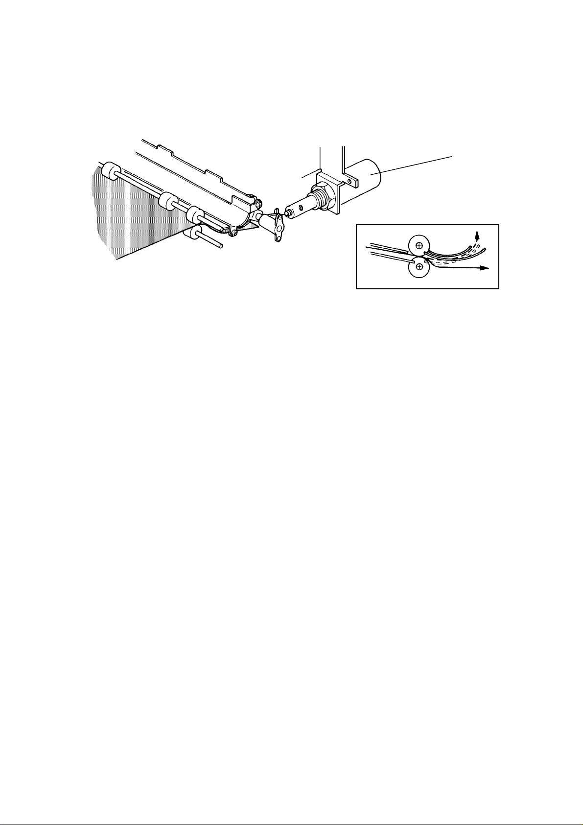
2.1 DRIVE MECHANISM
[C]
[A]
[B]
The sorter motor [A] is a servo motor and it is controled by the sorter CPU.
The sorter CPU also controls the motor rotation speeds: slow and high.
The sorter motor drives the sponge roller [B] and the other rollers through a
timing belt [C].
Sorter
9
Page 11

DETAILED SECTION DESCRIPTIONS 1 February 1994
2.2 BIN GATE OPERATION
[B]
[D]
[C]
[E]
[A]
Each bin gate shaft [A] is individually controlled by a solenoid. Normally, the
bin gates [B] are held out of the paper path by the return spring [C].
To feed paper into a bin, the sorter CPU energizes the appropriate solenoid.
The solenoid plunger [D] then rotates the bin gate lever [E] and opens the
gate out into the paper path. The curved inner face of the gate directs the
paper into the bin.
After the paper passes into the bin, the solenoid turns off and the return
spring pulls the bin gate lever back to the closed position.
10
Page 12

1 February 1994 DETAILED SECTION DESCRIPTIONS
2.3 RELAY GUIDE PLATE RESET MECHANISM
[B]
[C]
[A]
This mechanism prevents the relay guide plate [A] from being left up after
misfed paper has been removed from the sorter. When the operator closes
the sorter cover [B], the reset lever [C] is pushed down, returning the relay
guide plate to the horizontal position.
11
Sorter
Page 13

DETAILED SECTION DESCRIPTIONS 1 February 1994
2.4 ELECTRICAL CONTROL
Main System
DC
Power
Supply
24 V
GND
Board
Main
Board
CN150-1
CN120-1
Serial Interface
Sensors
Safety SWs
Sorter Main Board
+ 24 V
IC109
OSC
+ 5 V
Sorter
CPU
Solenoids
Motor
24 V is supplied from the copier, the sorter main board generates a 5 V
supply from the 24 V input.
The sorter has its own CPU which controls all the functions of the sorter. The
sorter CPU communicates with the copier through a serial interface bus.
Signals from the sensors and the safety switch are sent to the copier main
PCB. The copier main PCB sends the command signals for activation of the
motor and the solenoids to the sorter CPU.
12
Page 14

1 February 1994 DETAILED SECTION DESCRIPTIONS
2.5 JAM AND BIN COPY SENSORS
Upper
Lower
Detect
Circuit
+24V
+5V
CPU
+24V
Main Board
There is a jam sensor on the upper sensor board which detects sorter
misfeeds. A LED on the lower sensor board is turned on by a pulse signal
which is supplied from the sorter CPU.
When there is paper between either board, this pulse light does not activate
the phototransistor on the upper board. In this case, the sorter CPU
determines that the vertical drive roller is misfeeding a copy. This pulse signal
detection system has an advantage over a photointerruptor system because
there is no interference from external light.
Sorter
13
Page 15

DETAILED SECTION DESCRIPTIONS 1 February 1994
2.6 MISFEED SENSING
Copier’s
Exit Sensor
Inlet Sensor
Entry Sensor
T1
T2
T3
T4
The three components indicated in the above timing chart are involved in jam
detection. There are four jam detection tests, as follows.
T1: The inlet sensor is checked 80 pulses (0.36s) after the copier’s exit
sensor is turned ON. If the inlet sensor is not on, there is a jam is the
copier’s exit area.
T2: y pulses (see the table below) after the inlet sensor is turned ON, the
inlet sensor turns OFF. If the inlet sensor is not OFF, there is a jam
in the sorter entrance area.
T3: z pulses (see the table below) after the inlet sensor is turned ON, the
entry sensor turns ON. If the entry sensor is not ON, there is a jam in
the vertical transport area.
T4: z pulses after the inlet sensor is turned OFF, the entry sensor turns
OFF. If the entry sensor is not OFF, there is a jam in the sorter exit
area.
Paper Size 51/2 x 81/2 81/2 x 11 81/2 x 14 11 x 17 81/2 x 51/2 11 x 81/2
y pulse 380 484 620 752 240 376
Paper Size A3 B4 A4(L) A4(S) B5(L) B5(S) A5(L) A5(S)
y pulse 732 532 516 364 448 316 364 256
Bin No. 1 2 3 4 5 6 7 8 9 10 Print Interrupt
z pulse 992 904 860 816 772 724 680 632 588 544 360 316
14
Page 16

1 February 1994 INSTALLATION
3.INSTALLATION (DS5330)
3.1ACCESSORY CHECK
1. Installation Procedure (115 V version only)...........1 pc
2. NECR (115 V version only)...................................1 pc
3. Envelope for NECR (115 V version only)..............1 pc
4. Stud.......................................................................2 pcs
5. Knob Screw...........................................................2 pcs
6. Sorter Bin...............................................................11 pcs
7. Interrupt Bin...........................................................1 pc
8. Bin Cover...............................................................1 pc
9. Grounding Screw...................................................1 pc
15
Sorter
Page 17

INSTALLATION 1 February 1994
3.2 REMOVAL OF SHIPPING RETAINERS AND TAPES
[G]
[B]
[A]
[C]
[D]
[E]
[E]
[F]
1. Remove three pieces of tape:
Sorter Top Cover [A] (1 pc)
Transport Guide [B] (2 pcs)
2. Open the top cover [C] and remove the following items:
Tape [D] (1 pc)
Cushion [E] (4 pcs)
Fixing Clamp [F] (1 pc) [1 screw]
Card Board [G] (1 pc)
16
[E]
Page 18

1 February 1994 INSTALLATION
3.3 INSTALLATION PROCEDURE
[B]
[A]
[D]
[C]
[G]
[E]
1. Unplug the power supply cord.
2. Remove the rear lower cover [A] (4 screws).
3. Remove the 2 copy trays.
4. Remove the 5 caps [B] from the left cover [C].
5. Install the 2 short studs [D].
6. Remove the copier left cover [C] (4 screws).
[F]
7. Remove the inverter unit side covers [E] (2 screws each).
8. Swing down the inverter unit [F] (2 screws).
9. Remove the upper copy tray support bracket [G] (4 screws).
10. Reinstall the following parts:
• Inverter unit
• Inverter unit side covers
• Copier left cover
17
Sorter
Page 19

INSTALLATION 1 February 1994
[A]
[D]
[B]
[F]
[C]
[E]
11. Remove the sorter top cover [A] (3 screws).
12. Remove the sorter front cover [B] (2 screws).
13. Remove the sorter rear cover [C] (4 screws).
14. Install the sorter to the main system using holes [D]. (Connect the 2 studs
on the sorter to the machine system’s frame.)
15. Insert the sorter harnesses [E] through the hole on the left cover.
16. Fix the sorter to the main system with two screws (2 knob screws [F]).
18
Page 20

1 February 1994 INSTALLATION
[A]
[D]
[B]
[C]
17. Connect the following harnesses:
a) 4P connector [A] from the sorter to CN590 on the dc power supply unit
[B].
b) Fiber cable [C] from the sorter to CN157 on the main system’s main
PCB.
c) Grounding wire [D] (1 M4 x 8 grounding screw) as shown in the figure.
Sorter
19
Page 21

INSTALLATION 1 February 1994
[A]
[C]
[B]
[D]
18. Reinstall all covers.
19. Insert the 10 sorter bins [A].
20. Insert the print tray [B] in the 15th slot, then insert and push the bin cover
[C] firmly in the 14th slot.
NOTE: The print tray is interchangeable with the sorter bins.
21. Insert the interrupt bin [D].
22. Check the machine operation.
23. Confirm the customer’s requirements, as the following functions can be
selected if necessary:
• Auto Sort Mode: SP6-3
20
Page 22

28 December 1993 INSTALLATION
3.INSTALLATION (NC5006)
3.1ACCESSORY CHECK
Check the accessories according to the following list:
Description Q’ty
1. Installation Procedure...................................................................... 1
2. NECR............................................................................................... 1
3. Envelope for NECR......................................................................... 1
4. Stud................................................................................................. 2
5. Knob Screw..................................................................................... 2
6. Sorter Bin.........................................................................................11
7. Interrupt Bin..................................................................................... 1
8. Bin Cover......................................................................................... 1
9. Grounding Screw............................................................................. 1
Sorter Adapter
Description Q’ty
1. Fan Motor Assembly........................................................................ 1
2. Air Outlet Plate................................................................................ 1
3. Harness Clamp................................................................................ 2
4. Relay Harness................................................................................. 1
5. Edge Saddle.................................................................................... 2
6. Guide Plate Assembly..................................................................... 2
7. Philips Pan Head Screw -M4 x 6..................................................... 9
15
Sorter
Page 23

INSTALLATION 28 December 1993
3.2 INSTALLATION PROCEDURE
[G]
[A]
[C]
[D]
[E]
[B]
[E]
[F]
[E]
CAUTION: When installing the sorter, make sure that the copier is
unplugged.
NOTE: To install this sorter to A109 copier, A527 sorter adapter kit
(option) is necessary.
1. Remove three pieces of tape:
Sorter Top Cover [A] (1 pc)
Transport Guide [B] (2 pcs)
2. Open the top cover [C] and remove the following items:
Tape [D] (1 pc)
Cushion [E] (4 pcs)
Fixing Clamp [F] (1 pc) [1 screw]
Card Board [G] (1 pc)
16
Page 24

28 December 1993 INSTALLATION
[B]
[C]
[A]
[E]
[D]
3. Remove the upper rear cover [A] (4 screws).
4. Open the front doors then remove the left inner cover [B] (1 screw).
5. Remove the upper left cover [C].
6. Remove the 5 small caps [D].
7. Remove the 2 portions [E] with cutting pliers as shown.
8. Reinstall the upper left cover [C].
Sorter
17
Page 25

[D]
INSTALLATION 28 December 1993
[A]
[B]
[C]
[E]
9. Install the studs [A].
10. Install the upper guide plate [B] (2 screws).
11. Install the lower guide plate [C] (2 screws).
12. Remove the sorter top cover [D] (3 screws).
13. Remove the sorter rear cover [E] (4 screws).
14. Remove the sorter front cover (2 screws).
18
Page 26

28 December 1993 INSTALLATION
[A]
[B]
15. Remove the harness clamp [A] (1 screw).
16. Remove the two screws [B].
17. Install the two edge saddles [C] on the air outlet plate [D].
18. Install the plate [D] to the sorter rear frame (2 screws).
[D]
[C]
19
Sorter
Page 27

[E]
INSTALLATION 28 December 1993
[A]
[B]
[C]
[E]
[D]
19. Connect the connectors [A] of the accessory harness with the connectors
from the fan assembly.
20. Install the fan assembly [B] to the sorter rear frame
(3 screws and 1 connector).
21. Install the sorter to the main system using holes [C] (Connect the 2 studs
of the sorter to the main frame).
22. Insert the sorter harnesses [D] through the hole on the left cover.
23. Fix the sorter to the main frame with two screws (2 knob screws [E]).
20
Page 28

28 December 1993 INSTALLATION
[C]
[A]
[D]
[F]
[B]
[E]
[G]
24. Remove the protective cover and secure the 4p connector [A].
25. Secure the grounding wire [B]* (1 grounding screw with toothed washer).
NOTE*:For all models other than those intended for North America, the
green wire is intended as a functional earth ans should be
connected as shown.
26. Install two wire clamps [C].
27. Connect the fiber optics connector to the CN515 of the main control
board.
28. Insert the 10 sorter bins [D].
29. Insert the print tray [E] in the 15th slot, then insert and push the bin cover
[F] firmly in the 14th slot.
NOTE: The print tray is interchangeable with the sorter bins.
30. Insert the interrupt bin [G].
31. Install all covers on the copier and the sorter.
Sorter
32. Check the machine operation.
21
Page 29

1 February 1994 SERVICE TABLES
4. SERVICE TABLES
4.1 TEST POINT
NUMBER FUNCTION
TP100 Factory use only
TP101 24 V
TP102 5 V
TP103 0 V (GND)
4.2 LEDs
NUMBER FUNCTION
LED100 Lights when the inlet sensor is activated.
LED101 Lights when the entry sensor is activated.
LED102
Lights when the sorter motor speed is corrected in speed
adjustment
4.3 DIP SWITCH
DPS100
1 2 3 4
1 0 0 1 Free run without paper.
1 0 0 0 Free run with paper.
1 0 0 0
0 1 0 0
0 1 0 1
NOTE: DIP switches should all be OFF in normal mode.
(Paper feeding check)
Adjusts the motor speed in High Speed
mode by VR101.
Adjust the motor speed in Slow Speed mode
by VR100.
FUNCTION
4.4 VARIABLE RESISTORS
NUMBER FUNCTION
VR100 Adjusts slow speed of the motor.
VR101 Adjusts high speed of the motor.
21
Sorter
Page 30

REPLACEMENT AND ADJUSTMENTS 1 February 1994
5.REPLACEMENT AND ADJUSTMENTS
5.1SORTER REMOVAL (DS5330)
[C]
[G]
[A]
[B]
[H]
[D]
[E]
1. Turn off the main switch and unplug the machine.
2. Remove all bins.
3. Remove the rear lower cover of the copier (4 screws).
4. Open the sorter cover and remove the upper cover [A] (3 screws).
5. Remove the front [B] and rear [C] covers of the sorter (6 screws).
CAUTION: Do not remove the signal cable without turning off the
main switch.
6. Disconnect the following harnesses from the copier
a) 4P connector [D] from CN590 on the DC power supply unit [E].
b) Fiber cable [F] from CN157 on the copier’s main PCB [G].
c) Grounding wire [H] (1 grounding screw).
7. Remove the sorter from the copier (1 screw, 1 knob screws).
[F]
22
Page 31

1 February 1994 REPLACEMENT AND ADJUSTMENTS
5.2 SORTER MOTOR, SPONGE ROLLER, AND INLET
SENSOR REPLACEMENT
[E]
[F]
[D]
[B]
[C]
[A]
NOTE: Be careful not to lose the positioning pin [A].
1. Remove all sorter bins, then remove the sorter from the copier. (See the
Sorter Removal section.)
2. Remove the sorter motor [B] (4 screws, E-ring, ground-wire).
3. Remove the inlet guide board unit [C] (4 screws).
4. Remove the roller drive pulley (1 allen-screw) and replace the sponge
roller [D].
5. Remove the inlet sensor with the bracket on [E] (2 screws).
6. Pull out the harness and replace the sensor [F].
Sorter
23
Page 32

REPLACEMENT AND ADJUSTMENTS 1 February 1994
5.3 ENTRY SENSOR REPLACEMENT
- Entry Sensor Photo-transistor -
[A]
1. Turn off the main switch and unplug the machine.
2. Open the sorter cover and remove the upper cover (3 screws).
3. Disconnect the harness from the upper jam sensor board [A].
4. Remove the entry sensor board (2 screws).
CAUTION: Do not touch the variable resistor mounted on the sensor
board; it is factory adjusted.
- Entry Sensor LED -
[D]
[C]
[B]
1. Turn off the main switch and unplug the machine.
2. Remove all sorter bins.
3. Remove the antistatic brush [B] and the sensor cover [C] (2 screws).
4. Disconnect the harness from the lower sensor board [D].
5. Remove the entry sensor board (2 screws).
24
Page 33

1 February 1994 REPLACEMENT AND ADJUSTMENTS
5.4 VERTICAL DRIVE ROLLER TIMING BELT ADJUSTMENT
Standard:
14 ± 1.5 mm reflection at 200 g
Measurement: Take the measurement at the center, between
the pulley and the belt tightner roller [A].
Part to adjust: Belt tightner bracket [B] (1 screw)
200 g
14 ± 1.5 mm [A]
[B]
5.5 SORTER MOTOR SPEED ADJUSTMENT
CAUTION: - Always perform the high motor speed adjustment first.
- Make sure to check the low motor speed after adjusting
the high motor speed.
- LED102 takes sometime before responding to the
adjustment. Wait 2 to 3 seconds after adjusting the VR,
then check LED102.
1. Remove the sorter upper
cover (3 screws).
2. Remove the sorter rear cover
(4 screws).
3. Turn on DPS100-2, 4 on the
sorter main PCB. By using
VR100, adjust the high motor
speed so that LED 102 lights
on.
4. Turn on DPS100-2 on the
sorter main PCB. By using
VR101, adjust the low motor
speed so that LED102 lights
on.
Sorter
25
 Loading...