

Page 1

20 BIN SORTER
(MINI)
(Machine Code: A423)
Page 2

12 February 1992 SPECIFICATIONS
1. SPECIFICATIONS
Paper Size for Bins: Maximum A3, 11" x 17"
Minimum A5, 5
Paper Weight: 52 to 90 grams (14 to 24 lb)
Number of Bins: 20 bins + proof tray
1/2
" x 8
1/2
"
Bin Capacity: Sort Mode: 30 sheets/A4 (8
15 sheets/B4 (8
" x 11")
1/2
" x 14")
1/2
10 sheets/A3 (11" x 17")
Stack Mode 30 sheets/A4 (8
10 sheets/B4 (8
" x 11")
1/2
" x 14")
1/2
10 sheets/A3 (11" x 17")
Proof Tray Capacity: 100 sheets (all sizes)
Power Source: 100 V, 50/60 Hz, 0.6 A (from copier)
Power Consumption: 60 W
Dimensions:
(W x D x H)
346 mm x 474 mm x 338 mm
13.6" x 18.7" x 13.3"
Weight: 12.7 kg (28.3 lb)
(MINI)
20 Bin Sorter
1
Page 3
MECHANICAL COMPONENT LAYOUT 12 February 1992
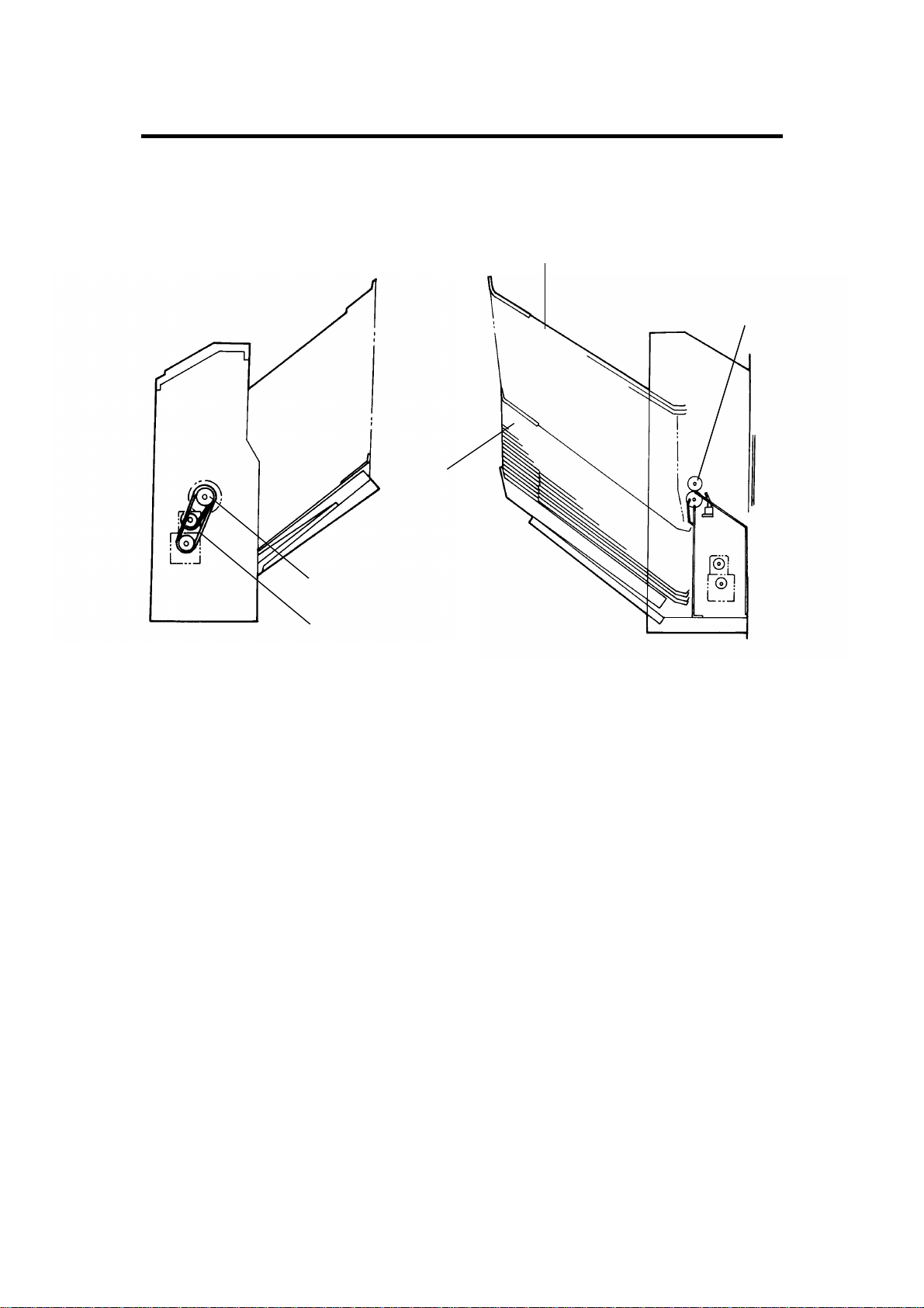
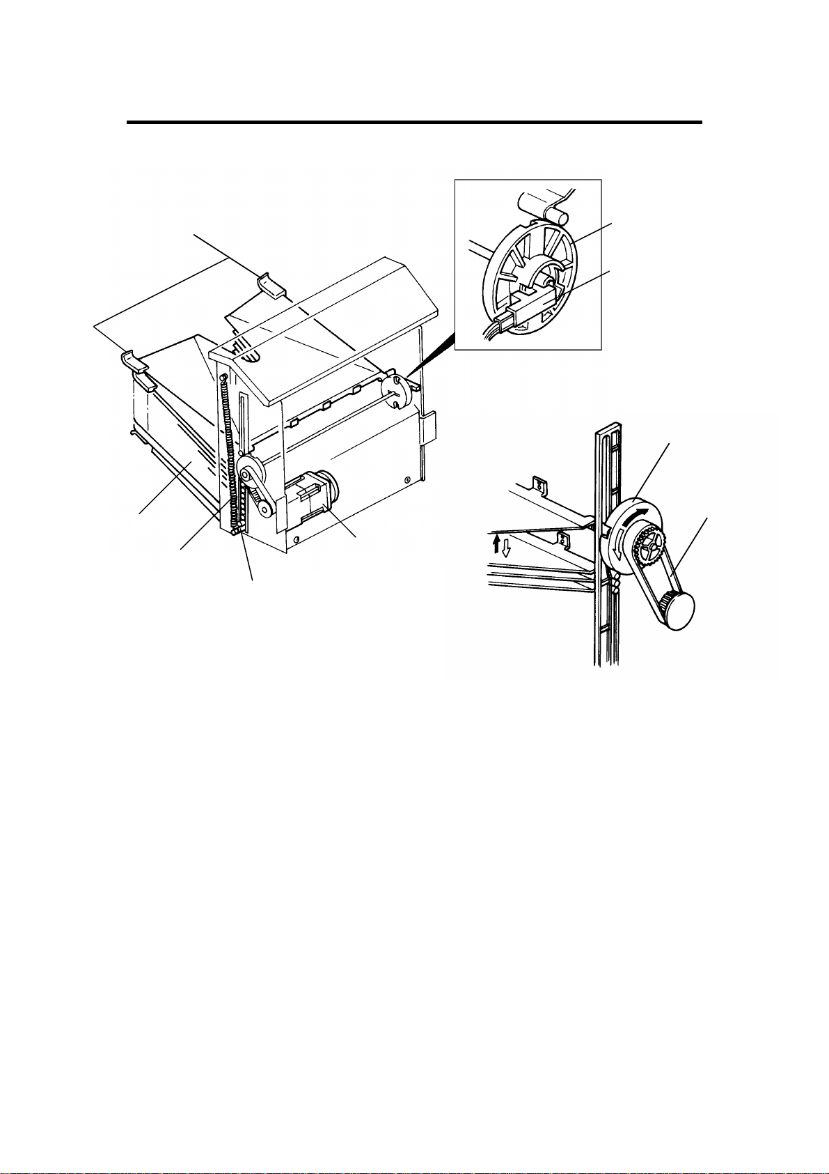
2. MECHANICAL COMPONENT LAYOUT
3
1
4
2
5
1. Exit Rollers
2. Bin Drive Wheel
3. Proof Tray
4. Bins
5. Roller Drive Belt
2
Page 4
12 February 1992 ELECTRICAL COMPONENT LAYOUT
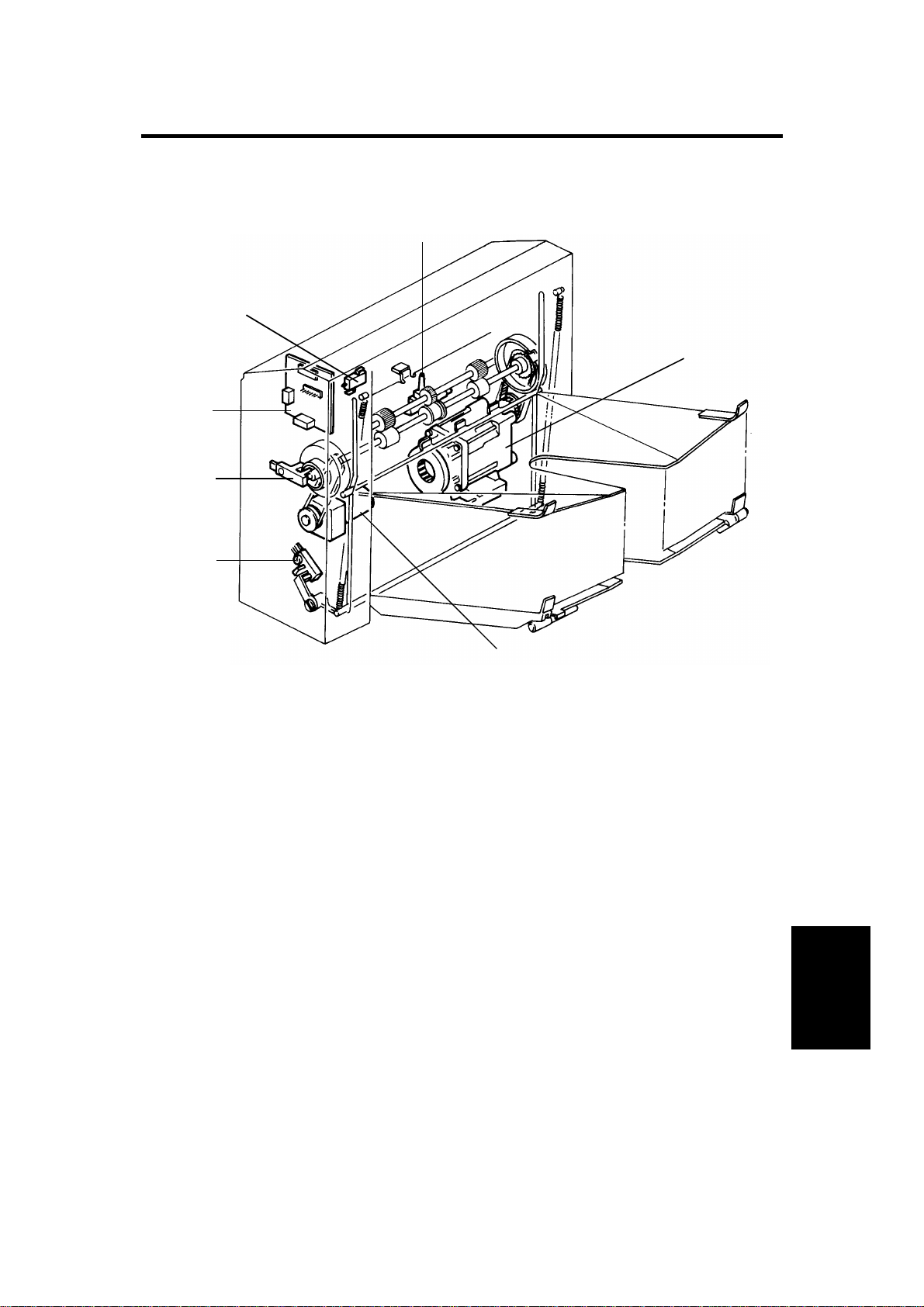
3. ELECTRICAL COMPONENT LAYOUT
1
7
2
6
5
4
3
1. Paper Sensor (S1)
2. Wheel Drive Motor (M1)
3. Roller Drive Motor (M2)
4. Bin Home Position Sensor (S2)
5. Wheel Sensor (S3)
6. Sorter Board (PCB1)
7. Cover Safety Switch (SW1)
(MINI)
20 Bin Sorter
3
Page 5

ELECTRICAL COMPONENT DESCRIPTIONS 12 February 1992
4.ELECTRICAL COMPONENT DESCRIPTIONS
Index No. Name Function Symbol
Motors
2
3
Sensors
1 Paper Sensor Misfeed detection for the sorter S1
4
5
Switch
7 Cover Safety Switch Detects when sorter cover is opened SW1
Wheel Drive Motor Drives the wheel that changes the
bin positions
Roller Drive Motor Drives all rollers in the sorter paper
path
Bin Home Position
Sensor
Wheel Sensor Detects each 1/2 turn of the wheel (1
Detects when all bins are in the
down position (home)
bin changed for each 1/2 turn)
M1
M2
S2
S3
Printed Circuit Board
Sorter Board Controls all sorter functions.
6
Communicates with I/O control PCB
through the interface PCB
PCB1
4
Page 6

12 February 1992 BASIC OPERATION
5.BASIC OPERATION
5.1CLEAR MODE
When the main switch of the copier is turned on, the sorter automatically
assumes a clear mode condition. It also changes to a clear mode condition if
the sort or stack mode is recalled or if the interrupt key is pressed. In a clear
mode condition, all copies are stacked on the proof tray.
Sorter operation starts when a sheet of copy paper activates the copier exit
sensor. At this time the roller drive motor energizes. The
roller drive motor de-energizes when the paper exits the copier and the paper
sensor is deactivated. The paper senso r signa l is sent to the copie r through an
interface board to check for paper misfeed. The wheel drive motor does not
turn on when in the clear mode.
5.2SORT MODE
After the sort mode is selected by pr e ssing the Sorter key, the wheel drive
motor turns on to move the proof tray up. When the first sheet of paper
activates the copier exit sensor, the roller drive motor turns on. Shortly after
the paper sensor turns off (420 ms later), the wheel drive motor turns and
advances the bins one step. When t he whee l senso r is acti vat ed , th e whe el
drive motor turns off.
5.3STACK MODE
As in the sort mode, the roller drive motor turns on when the first sheet of
paper actuates the copier exit sensor. All copies of the copy run are then fed
to the first bin. When the final copy passes the paper sensor, the wheel drive
motor turns on and advances the bins one step.
There are no limits on the number of copies that can be entered up to the full
999 copy limit of the copier. However, the physical capacity of the bins is a
good deal less. (See "Bin Capacity" in the specifications.)
When all 20 bins have been used, the wheel drive motor turns on until all the
bins have been lowered (including the proof tray).
(MINI)
20 Bin Sorter
5
Page 7
EXAMPLE OF SORT MODE OPERATION 12 February 1992
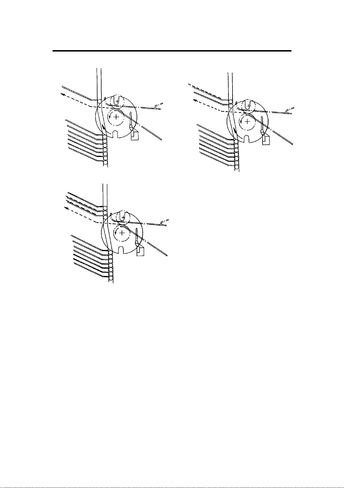
6. EXAMPLE OF SORT MODE OPERATION
1) 2)
3)
"3" copies entered/Start key pressed 3 times.
- Start Key ON -
1) The first copy feeds to the first bin. After the paper sensor turns off, the
wheel drive motor turns on and moves the first bin up.
2) The same action as #1.
3) The third copy feeds to the third bin . The whee l dr ive mot or do es no t tu r n
on after the paper sensor turns off. (The sorter will stay at this position
until auto-reset or until copying resumes.)
6
Page 8
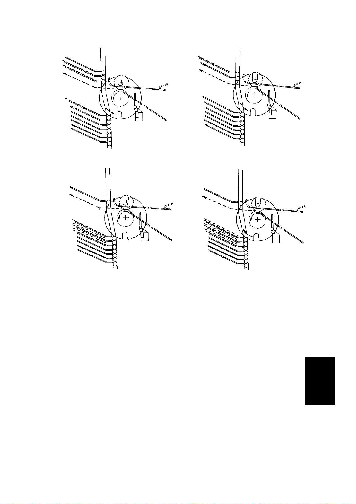
12 February 1992 EXAMPLE OF SORT MODE OPERATION
4) 5)
6)
7)
- Start Key ON -
4) The first copy is fed to the third bi n. After the paper sensor turns off, the
wheel drive motor turns on and moves the second bin down.
5) The same as #4.
6) The third copy is fed to the first bin. The wheel drive motor does not turn
on after the paper sensor turns off.
- Start Key ON -
7) The first sequence (1, 2, and 3) is repeated.
7
(MINI)
20 Bin Sorter
Page 9
BIN DRIVE MECHANISM 12 February 1992
7. BIN DRIVE MECHANISM
[A]
[G]
[C]
[D]
[I]
[H]
[B]
[F]
[E]
The bin drive mechanism moves the bins [A] up an d do wn to re ceive copie s
under the direction of the copie r CPU. The ma in comp onents in this
mechanism are the wheel drive motor [B], the two transfer wheels [C], the
wheel sensor [D], and the bins themselves.
Pins on either side of each bin are inserted into slots in the sorter side frame.
The pins slide up and down in these slots. The bins r est on ea ch ot her with
the lower one resting on the lift bar [E ]. The spr ings [F], on either end of the
lift bar, lift it up forcing the bin pins against the transfer wheels. Plastic
spacers [G] on both ends of the bin keep the bins separated.
To move the bins up, the bin drive motor turns clockwise (as viewed from the
front). A timing belt [H] turns the transfer wheels [I].
8
Page 10
12 February 1992 BIN DRIVE MECHANISM
[A]
[B]
[C]
[E]
[D]
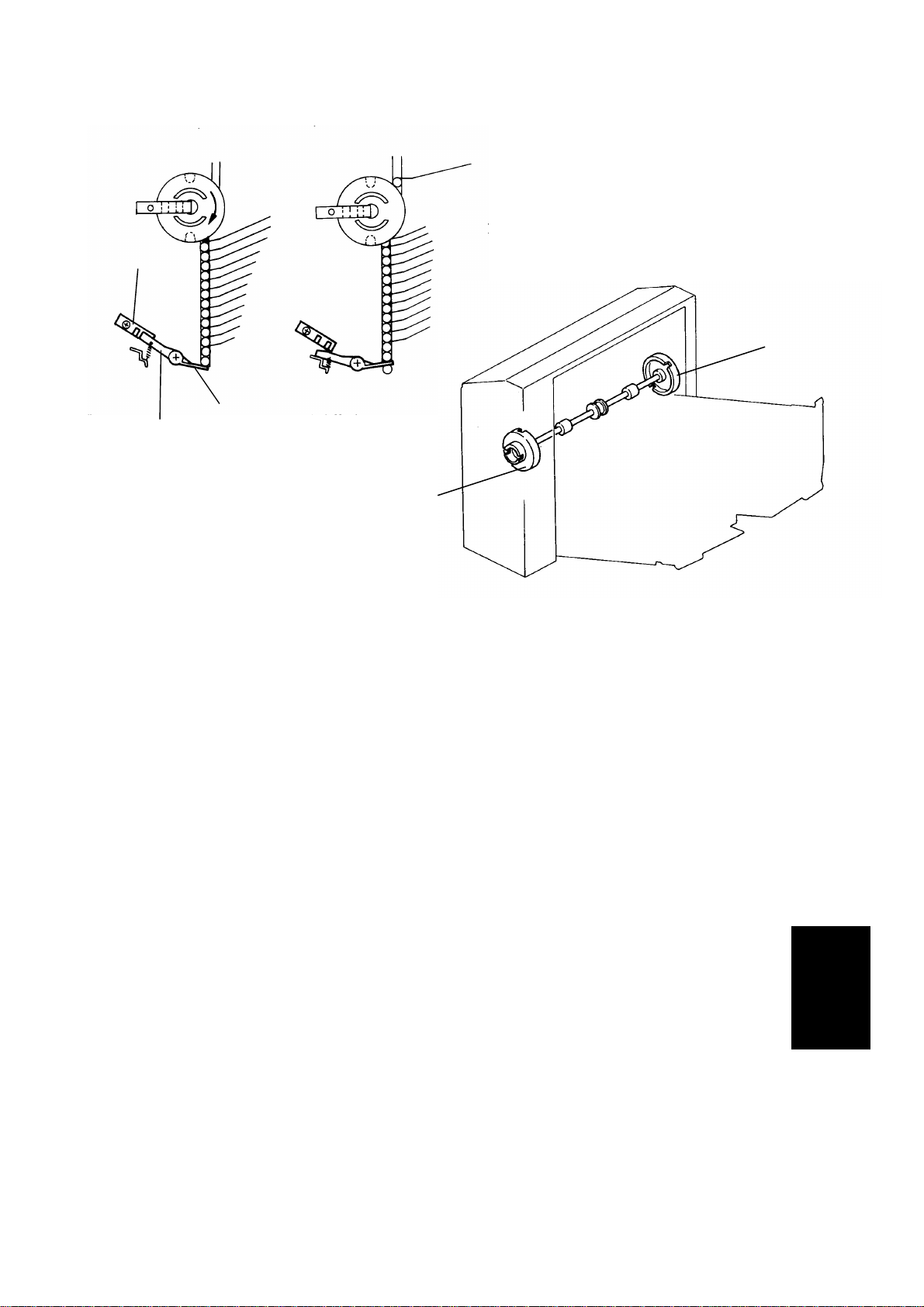
The transfer wheels have two slots in them 18 0 de gr e es ap ar t . As th e
transfer wheels turn, these slots en gage the pins of the bins and lift them up.
Each time the transfer wheels tu r n 18 0 de gr e es, the y ra ise on e bin .
The CPU counts the bins using the wheel sen sor . A cylindr ica l ac tu at or on
the front transfer wheel turns the wheel sensor on and off. This actuator has
two notches that are 180 de grees apart. The wheel sensor turns on each
time one of the slots passes through the sensor.
To move the bins down, the CPU reverses the bin drive motor and the above
process reverses.
The home position sensor [A] is locat ed at th e lowe r re ar en d of the sor te r .
When all the bins are lowered, the lift bar [B] presses down on the actuator
[C], actuating the sensor. The CPU checks the sensor whenever the power is
turned on. At this time, if the bins are not in the home position, the home
position sensor is deactuated the CPU will return the sorter bins to the home
position.
The mounting position is about 18.5 degrees off between the front tran sfe r
wheel [D], and the rear transfer wheel [E]. Therefore, the front and rear of the
bins do not rise simultaneously thus avoiding unusual noises and also
reducing load.
(MINI)
20 Bin Sorter
9
Page 11
BINS 12 February 1992
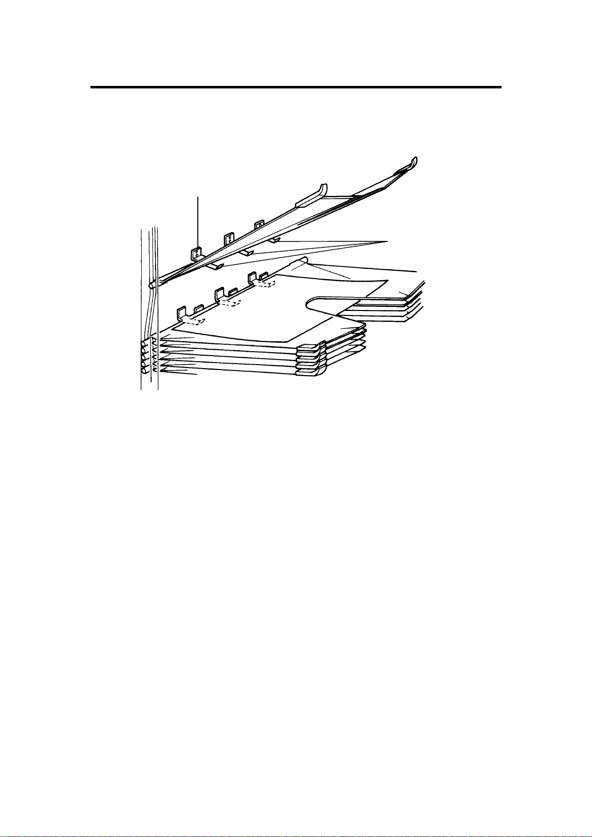
8. BINS
[A]
[B]
The proof tray and the twenty bins are all basically the same. Formed out of
thin flexible steel plate, they ha ve spa cer s on the left end to hold them apart
and pins at the front and rear of the right end, which are inserted in guide
slots in the sorter frame.
On the right edge, the bins have stoppers [A] which prevent copies from
sliding back into the sorter after they have been fed out. The pattern of these
stoppers is different for even and odd numbered bins.
Three leaf springs [B] on the underside of each bin hold the copies flat in the
underlying bin.
10
Page 12
12 February 1992 EXIT ROLLERS
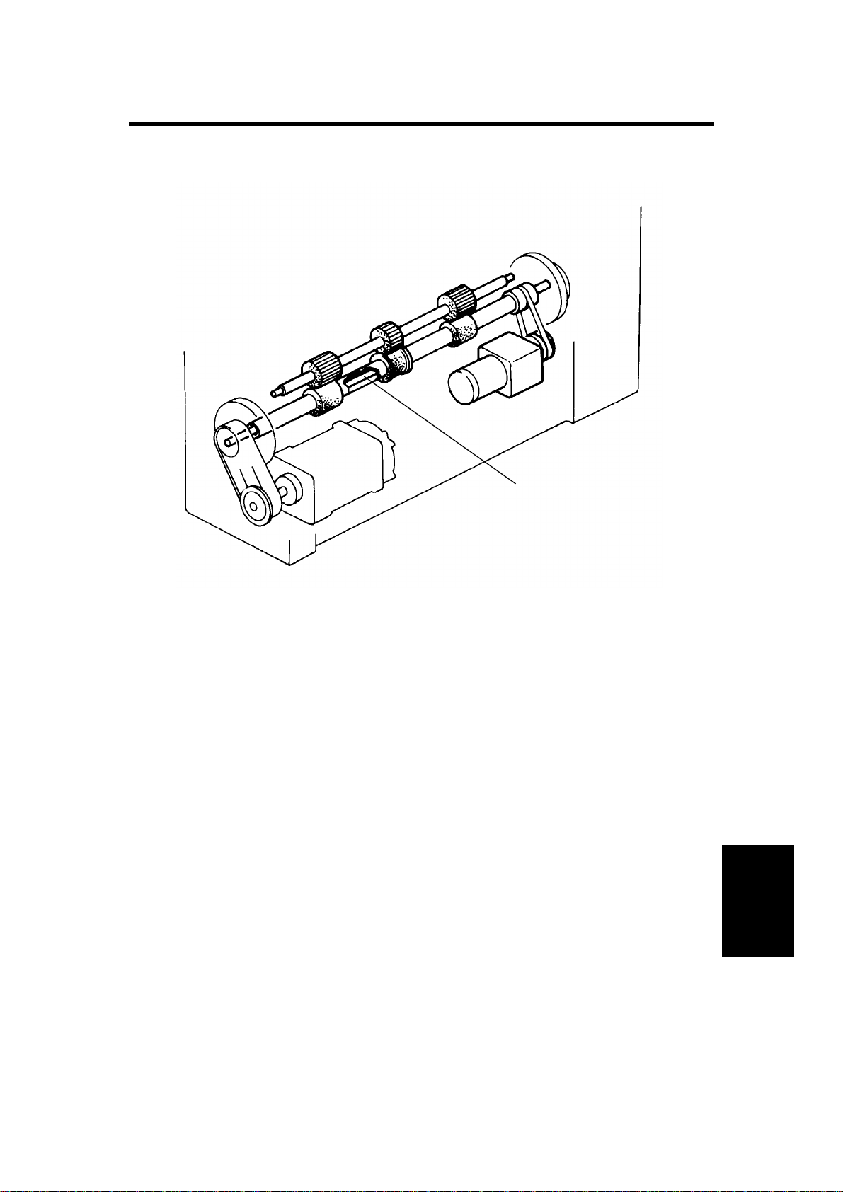
9. EXIT ROLLERS
[A]
The exit roller shaft is hollow and is mounted on the transfer wheel shaft [A]
(coaxial). When the copy actuates the copier’s exit sensor, the CPU sends a
signal to the sorter to turn on the roller drive motor. The roller drive motor
turns off at the same time as the copier main motor.
(MINI)
20 Bin Sorter
11
Page 13

ELECTRICAL TIMING 12 February 1992
10.ELECTRICAL TIMING
Fusing Exit Sensor
(Copier)
Paper Sensor
Roller Drive Motor
Wheel Drive Motor
Wheel Sensor
T1
1.76
1.57
JAM
T2
0.42
JAM
0.75
T3 T4
1.76
1.57
T1:When a sheet of copy paper activates the fusing exit sensor,
the roller drive motor starts rotating.
T2:1.57 seconds after turning on the fusing exit sensor, the paper
sensor turns ON.
0.42
T5
T3:0.42 second after the paper sensor turns OFF, the wheel drive
motor starts rotating and shifts the bin.
T4:When the wheel sensor is actuated, the wheel drive motor
turns OFF.
T5:0.42 second after the paper sensor turns OFF, the roller drive
motor stops.
12
Page 14

12 February 1992 INSTALLATION
11.INSTALLATION (FT4227/5233 SERIES)
11.1ACCESSORY CHECK
Check the quantity and conditio n of the accesso r ies in th e box according to
the following list:
1. Installation Procedure......................................................................1
2. New Equipment Condition Report
(–17, –27 machines only)................................................................1
3. Envelope for NECR
(–17 machine only)..........................................................................1
4. Thumb Screw..................................................................................1
5. Grounding Screw............................................................................1
6. Star Washer...... ...............................................................................1
7. Multilingual Decal
(–25, –26, –27 machines only)........................................................1
13
(MINI)
20 Bin Sorter
Page 15

INSTALLATION 12 February 1992
11.2 INSTALLATION PROCEDURE
[A]
[A]
[E]
[A]
[D]
[B]
[F]
CAUTION: Unplug the copier power cord before starting the following
procedure.
NOTE: •
The sorter adapter (A328) should be installed before the sorter is
installed.
[G][C]
1. Remove the strips of tape [A].
2. Remove the front sorter cover [B] (2 screws) and rear sorter cover [C] (4
screws).
3. Remove the cover plates [D] with cutting pliers and the plastic cap [E].
4. Mount the sorter on the copier. Insert the two mounting studs into the
docking holes, and pass the harness [F] through the access hole.
5. Attach the sorter unit to the copier with the two thumb screws [G].
14
Page 16

12 February 1992 INSTALLATION
[A]
[B]
6. Secure the sorter protective earth wire [A] (1 screw and toothed washer).
7. Connect the three connectors [B] as follows:
2P red to 2P red free
4P white to 4P white free
11P white to 11P white free
(MINI)
20 Bin Sorter
15
Page 17

INSTALLATION 12 February 1992
[B]
[A]
8. Reinstall all the covers.
9. Plug in the copier power cord.
10. While pressing both 1 and 3 on the ope r at ion pan el nu mbe r keys, tu r n on
the main switch in order to access the SP mode.
NOTE:
Release the number keys after conf ir m ing tha t th e call ser vice
indicator and the copy coun ter number "0" are blinking.
11. Enter 71 using the number keys and then press the enter key.
12. Enter 2 using the number keys and then press the enter key.
13. Turn off the main switch.
14. Remove the left plastic cover [A] on the operation panel and install the
sorter key top and cover [B] instead.
NOTE:
The sorter key top and cover are provided as an accessory for
the copier.
15. Turn on the main switch and check the sort er ’s op er a tio n.
16
Page 18

28 February 1989
12. ACCESSORY CHECK (FT4460)
Check the quantity and condition of the accessories in the box according to
the following list:
1. Installation Procedure
(115V - English only / 220V - Five Languages)
2. New Equipment Condition Report . . . . . . . . . . . . . . . . . . . . . . . . 1
3. Envelope for NECR (115V only)
. . . . . . . . . . . . . . . . . . . . . . . . . . . . . . . . . . . . . . . . . . .
. . . . . . . . . . . . . . . . . . . . . . . . . . .
1
1
4. Thumb Screw
5. Grounding Screw
7. Multilingual Decal (220/240V only) . . . . . . . . . . . . . . . . . . . . . . . . 1
. . . . . . . . . . . . . . . . . . . . . . . . . . . . . . . . . . . . . . . . . . . . . . . . . . . . . . .
. . . . . . . . . . . . . . . . . . . . . . . . . . . . . . . . . . . . . . . . . . . . . . . . .
2
1
8-13
Page 19

28 February 1989
13. INSTALLATION PROCEDURE (FT4460)
NOTE:
1.
2
.
.
3
4.
.
5
.
6
7.
Install the sorter unit after the optional date printer and the
document feeder have been installed.
Turn off the main switch and unplug the power supply cord of the copier.
Remove the strips of shipping tape [A].
Remove the receiving tray [B] and rear cover [C] of the copier (4 screws).
Remove the 5 plastic caps [D].
Remove the front sorter cover [E] (2 screws) and rear sorter cover [F] (4
screws).
Mount the sorter on the copier. Insert the two mounting studs into the
docking holes, and pass the harness through the access hole.
Attach the sorter unit to the copier with the two thumb screws [G].
8-14
Page 20

28 February 1989
8. Connect the sorter ac harness [A] (free red 2P connector).
9. Connect the sorter dc harness [B] (white 4P connector).
10. Connect the sorter harness [C] (CN2, white 11P connector).
11. Secure the sorter ground wire [D] (1 screw and star washer).
12. Mount the sorter covers and copier rear cover.
13. Remove the sheet [E] on the left end of the operational panel, and insert
the sorter key top [F] into the key hole. Then, stick on the sorter panel
sheet [G].
NOTE:
The sorter panel sheet and sorter key top are copier accessories.
8-15
Page 21

28 February 1989
14. Remove the key cover [A] (1 screw).
15. Plug in the power cord of the copier and turn on the main switch.
16. Turn on DIP SW 1-4 under the operation panel.
17. Enter “71” in the copy counter using number keys, then press the “#” key.
18. Enter “1” in the magnification ratio indicator using number keys, then
press the “#” key.
19. Turn off DIP SW 1-4 under the operation panel.
20. Install the key cover.
21. Check the sorter’s operation and fill out the New Equipment Condition
Report.
8-16
Page 22

1 January 1990
12. ACCESSORY CHECK (NC100)
Check the quantity and condition of the accessories in the box according to
the following list:
1. Installation Procedure..............................................1
2. New Equipment Condition Report...........................1
(17 and 27 machines)
3. Envelope for NECR (17 machine only). .. .. .. .. .. .. .... ..1
4. Thumb Screw..........................................................2
5. Grounding Screw.....................................................1
6. Star Washer.............................................................1
7. Multilingual Decal (16, 25, 26 and 27 machines)....1
8. Transport Mylar (for A030)...... .. .. .... .. .. .. .. .. .. .... .. .. .. ..1
8-14
Page 23

1 January 1990
12.1 INSTALLATION PROCEDURE (for Machine Code: A030)
[A]
[C]
[A]
[E]
[D]
[F]
1.Turn off the main switch and unplug the power supply cord of the copier.
2.Remove the strips of shipping ta pe [A].
3.Remove the receiving tray [B], ton er colle ction bottle cover [C] (2 screws)
and rear cover of the copier [D] (5 screws).
4. Remove the 5 plastic caps [E].
5. Stick the transport mylar [F] to the sorter as sho wn.
8-15
Page 24

1 January 1990
[A]
[B]
[C]
[D]
6.Remove the fusing exhaust fan [A] (2 screws ,1 connector).
7. Remove the front sorter cover [B] (2 screws) and rear so rte r cover [C] (4
screws).
8. Mount the sorter on the copier. Insert th e two moun tin g stu ds int o th e
docking holes, and pass the harness th rou gh the access ho le.
9. Fix the sorter unit to the copier with the two thumb screws [D].
8-16
Page 25

[G]
[A]
[B]
[C]
1 January 1990
[D]
[F]
[H]
[E]
10.Connect the sorter AC harness [A] (free red 2P connector), DC harness
[B] (white 4P connector) and harne ss [C] (CN2, white 11P connector).
11.Secure the sorter ground wire [D] (1 screw and sta r wa she r).
12.Remove the bracket [E] (1 screw).
13.Mount the sorter covers, fusin g fan exhaust and copier covers.
14.Remove the sheet [F] on the le ft end of th e op era tional panel, and insert
the sorter key top [G] int o the key hole. Then, stick on the sorte r pan el
sheet [H].
NOTE: The sorter panel sheet and sorter key top are copier accessories.
15.Enter SP mode. Then, enter sorte r mo de as follo ws:
7
16.Leave SP mode by pressing the Clear Modes key.
1
#
1
8-17
#
Page 26

ACCESSORY CHECK 20 December 1991
12.ACCESSORY CHECK (NC305)
Check the quantity and condition of the accessories in the box according to
the following list:
1. Installation Procedure........................................................................1
2. New Equipment Condition Report.....................................................1
(17 and 27 machines)
3. Envelope for NECR (17 machine only). .. .. .. .. .. .. .... .. .. .. .. .. .. .... .. .. .. .. .. ..1
4. Thumb Screw....................................................................................2
5. Grounding Screw...............................................................................1
6. Star Washer.......................................................................................1
7. Multilingual Decal (16, 25, 26 and 27 machines)..............................1
8. Transport Mylar (for A030/A072). .. .... .. .. .. .. .. .. .... .. .. .. .. .. .. .... .. .. .. .. .. .. ....1
14
Page 27

[D]
[B]
20 December 1991 ACCESSORY CHECK
12.1 INSTALLATION PROCEDURE (for Machine Code: A072)
[A]
[A]
[A]
[E]
[D]
[C]
1. Turn off the main switch an d un plu g the power supply cord of the copier.
2. Remove the strips of shipping tape [A].
3. Remove the receiving tray [B] , and op en the rear cove r [ C] (2 screws).
4. Remove the five plastic caps [D].
5. Stick the transport mylar [E] to the sort er as shown.
15
Page 28

[C]
ACCESSORY CHECK 20 December 1991
[A]
[B]
[G]
[F]
[E]
[D]
[H]
6. Remove the front sorter cove r [A] (2 screws) a nd re ar sort er cove r [ B] (4
screws).
7. Mount the sorter on the copie r. Insert the two mounting stud s into the
docking holes, and pass the ha rness through the access hole .
8. Fix the sorter unit to the copier with the two thumb screws [C].
9. Connect the sorter AC harness [D] (free red 2P connector), DC harness
[E] (white 4P connector) and harn ess [F] (CN2 , whit e 11 P con ne cto r).
10. Secure the sorter ground wire [G] (1 screw and star wa she r).
11. Remove the bracket [H] (1 screw).
12. Mount the sorter covers and copie r co ver.
16
Page 29

20 December 1991 ACCESSORY CHECK
13. Enter SP mode. Then, enter sorter mode as follows:
71
14. Leave SP mode by pressing the Clear Modes Key.
R/#
1
R/#
17
Page 30

12 February 1992 REPLACEMENT AND ADJUSTMENT
12. REPLACEMENT AND ADJUSTMENT
12.1 EXIT ROLLER AND O-RING REPLACEMENT
[A]
[E] [B]
[B]
[C]
[D]
1. Remove the sorter from the copier.
2. Remove the front and rear covers (2 screws each).
3. Remove the ground wire [A] of the upper guide plate [B] (1 screw).
4. Swing the guide plate up, then remove it by carefully pulling it up.
5. Remove the inner cover [C] (4 screws).
6. Unhook the front [D] and rea r [E] pr essu r e spri n gs.
(MINI)
20 Bin Sorter
17
Page 31

REPLACEMENT AND ADJUSTMENT 12 February 1992
CAUTION: Do not damage the paper sensor [K] when removing the
exit roller.
[A]
[B]
[C]
[K]
[J]
[D]
[H]
[G]
[I]
[F]
[E]
7. Remove the wheel sensor assembly [A] (1 screw).
8. Remove the rear transfer wheel [B] (1 E-ring).
NOTE:
Be sure not to lose the pin [C] for the wheel.
9. Remove the pin and bushing [D].
10. Loosen the four mounting screws [E] of the wheel drive motor [F].
11. Lift the wheel drive motor and slip off the timing belt [G].
12. Slide off the wheel drive shaft [H] and remove the exit roller [I]
and O-ring [J].
13. Replace the exit roller and O- ri n g, the n rea ssem b le.
NOTE:
a) When reinstalling the wheel sensor assembly, be sure that the
sensor does not touch the wheel.
b) When remounting the wheel drive mo to r , ad just the ti m ing belt
tension. (See Timing Belt Tension Adjustment.)
18
Page 32

12 February 1992 REPLACEMENT AND ADJUSTMENT
12.2 PAPER SENSOR REPLACEMENT
CAUTION: To avoid damaging the sensor, do not over-tighten the
sensor mounting screw.
[A]
[C]
[B]
1. Remove the sorter from the copier.
2. Swing up the guide plate [A].
3. Remove the inner cover [B] (4 screws).
4. Replace the paper sensor [C] (1 screw and 1 connector) and reassemble.
19
(MINI)
20 Bin Sorter
Page 33

REPLACEMENT AND ADJUSTMENT 12 February 1992
12.3 TIMING BELT TENSION ADJUSTMENT
200g (0.44 lb)
[C]
[D]
[A]
2 mm
0.080
[B]
+3
mm
−0
+0.12
−0
ADJUSTMENT STANDARD:
2 mm
+3
mm; 0.080
−0
+0.12
−0
inches
(deflection at 200 g (0.44 lb) pressure)
1. Remove the front cover.
2. Loosen the four mounting screws [A] of the wheel drive moto r [B].
3. Press the timing belt [C] with a tension gauge [D] as shown in the figure
and adjust the tension by repositioning the wheel drive motor.
20
Page 34

28 February 1989
13. ELECTRICAL CONTROL (FT4460)
The copier I/O control PCB controls all the functions of the sorter through the
interface board.
The copier supplies 100 volts ac to the wheel drive motor and the SSRs. SSR
101 turns the wheel drive motor to move the bins up and SSR 102 is for the
down operation.
The copier supplies two dc power levels, +5 volts and +24 volts, for the dc
components.
Signals from the sensors and the safety switch are sent to the copier I/O con-
trol PCB through the interface board. The copier I/O control PCB operates
motors and SSRs.
8-12
Page 35

13. ELECTRICAL CONTROL (NC100)
1 January 1990
Copier
Main PCB
BIN UP
BIN DOWN
ROLLER
PAPER
WHEEL
H.P.
COVER
100 Vac
100 Vac
Sorter Interface
PCB
24V
5V
GND
Sorter Control Board
SSR 101
24V
5V
SSR 102
100 Vac
Up
Down
Wheel
Drive
Motor
Roller
Drive
Motor
Paper
Sensor
Wheel
Sensor
H.P.
Sensor
Cover
Safety
The copier supplies 100 volts ac to the wheel drive motor and the SSRs. SSR
101 turns the wheel drive motor to move the bins u p and SSR 102 is for the
down operation.
The copier supplies two dc power levels, +5 volts and +24 volts, for the dc
components.
Signals from the sensors and the safety switch are sent to the copier main
PCB. The copier main PCB controls motors and SSRs.
8-13
Page 36

20 December 1991 ELECTRICAL CONTROL
13.ELECTRICAL CONTROL (NC305)
Copier
Main PCB
BIN UP
BIN DOWN
ROLLER
PAPER
WHEEL
H.P.
COVER
100 Vac
100 Vac
Sorter Interface
PCB
24V
5V
GND
Sorter Control Board
SSR 101
24V
SSR 102
5V
100 Vac
Up
Down
Wheel
Drive
Motor
Roller
Drive
Motor
Paper
Sensor
Wheel
Sensor
H.P.
Sensor
Cover
Safety
The copier supplies 100 volts ac to the wheel drive motor and the SSRs. SSR
101 turns the wheel drive motor to move the bins u p and SSR 102 is for the
down operation.
The copier supplies two dc power levels, +5 volts and +24 volts, for the dc
components.
Signals from the sensors and the safety switch are sent to the copier main
PCB. The copier main PCB controls motors and SSRs.
13
Page 37

4. SORTER
4. SORTER
Index No.
1.
2.
3.
4.
5.
6.
7.
8
9.
10.
11.
12.
13.
14.
15.
CN. No.
CN101
CN103
CN
104
T1
T2
CN116
CN117
CN115
CN113
CN111
CN114
CN102
CN2
CN902
CN3
Component
Sorter Board
Sorter Board
Sorter Board
Cover Safety Switch
Cover Safety Switch
Paper Sensor
Wheel Drive Motor
Roller Drive Motor
H.P. Sensor
Wheel Sensor
(Relay Drive Motor)
Sorter Board
Sorter Interface Harness
Sorter DC Harness
Sorter
AC Harness
--
Type
__
2P/W
12P/R
15P/W
P/W
3P/w
3P/W
3P/W
3P/W
3P/W
2P/W
3P/W
11P/W
4P/W
2P/R
--
--_-
H-7
G-617
H-6
H-7
H-7
P
to
H-8
H-7
ti-8
ti-9
H-8
ti-8
HH-7
G-6/7
F
-6
H-6
P
 Loading...