

Page 1

3-BIN SORTER
(Machine Code: A849)
Page 2

24 February, 1999 MECHANICAL COMPONENT LAYOUT
1. SPECIFICATIONS
Paper Size for Bins: Sort/Stack Modes:
Lengthwise: A6 to A3
5
1/2
Sideways: A5 to A4
5
1/2
Paper Weight for Bins: Face up:
1st bin: 52 ~ 160 g/m2 (14 ~ 42 lbs.)
2nd/3rd bins: 52 ~ 105 g/m2 (14 ~ 28 lbs.)
Face down:
All bins: 64 ~ 105 g/m2 (17 ~ 28 lbs.)
Bin Capacity: 1st bin:
A4, 8
B4, 8
2nd/3rd bins:
A4, 8
B4, 8
1/2
" x 8
" x 8
" x 11" or smaller:
1/2
" x 13" or larger:
1/2
" x 11": or smaller:
1/2
" x 13" or larger:
" (HTL) to 12" x 18"
1/2
" (HTL) to 8
1/2
" x 11" (LT)
1/2
500 copies (80 g/m2, 20lbs.)
250 copies (80 g/m2, 20 lbs.)
250 copies (80 g/m2, 20lbs.)
125 copies (80 g/m2, 20lbs.)
Number of Bins: 3 copy trays
1 inverter tray
Power Source: DC 24 V, 5 V (from the main machine)
Power Consumption: Average: Less than 30 W
Weight: 13 kg (28.7 lbs.)
Weight: 14 kg (30.9 lbs.)
Dimensions (W x D x H): 361 x 483 x 427 mm (14.3" x 19.1" x 16.9")
Options
A849-1
Page 3
MECHANICAL COMPONENT LAYOUT 24 February, 1999
2. COMPONENT LAYOUT
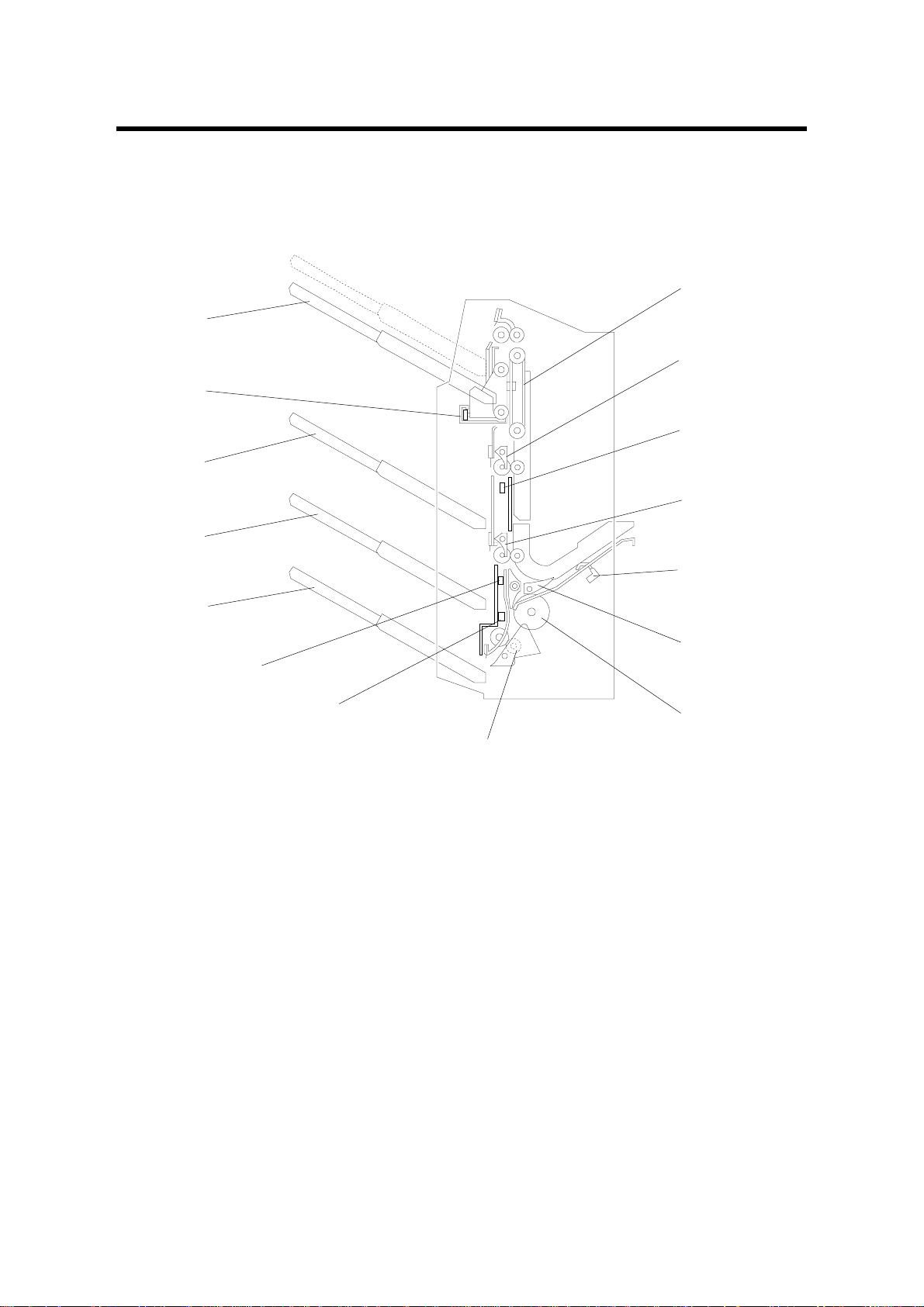
2.1 MECHANICAL COMPONENT LAYOUT
1
15
2
14
3
13
4
12
11
10
1. Tray Lift Belt
2. 2nd Bin Gate
3. 2nd Exit Sensor
4. 3rd Bin Gate
5. Entry Sensor
6. Junction Gate
7. Feed Roller
5
6
9
8
9. Inverter Sensor
10. 3rd Exit Sensor
11. Inverter Bin
12. 3rd Bin
13. 2nd Bin
14. Tray Lower Limit Sensor
15. 1st Bin
A849V001.WMF
7
8. Return Pinch Roller
A849-2
Page 4

24 February, 1999 DRIVE LAYOUT
2.2 DRIVE LAYOUT
1
4
A849V002.WMF
3
1. Entry Roller
2. Feed Roller
3. Entrance Motor
2
5
6
9
7
8
A849V003.WMF
6. 3rd Exit Roller
7. Inverter Roller
8. Return Pinch Roller
4. 1st Exit Roller
5. 2nd Exit Roller
9. Exit Motor
Options
A849-3
Page 5
ELECTRICAL COMPONENT DESCRIPTION 24 February, 1999
2.3 ELECTRICAL COMPONENT DESCRIPTION
Refer to the electrical component layout on the reverse side of the point-to- point
diagram (on waterproof paper).
Symbol Index No. Description Note
Motors
M1 13 Entrance Drives the feed roller and the entry roller.
M2 14 Exit Drives the inverter roller and the exit rollers.
M3 18 Tray Shift Moves the 1st bin from side to side.
M4 16 Tray Lift Moves the 1st bin up or down.
Solenoids
SOL1 4 2nd Bin Gate Opens and closes the 2nd bin gate to direct
the copies into either the 2nd bin or 1st bin.
SOL2 5 3rd Bin Gate Opens and closes the 3rd bin gate to direct
the copies into either the 3rd bin or the other
bins.
SOL3 6 Junction Gate Opens and closes the junction gate to direct
copies into either the inverter area or other
exits.
SOL4 7 Pinch Roller In face down mode, contacts the return
pinch roller with the copy to deliver the copy
to bin 1, 2, or 3.
Sensors
S1 2 Stack Height
S2 17 Tray Half-turn
S3 1 1st Exit Detects paper jams at the 1st bin.
S4 8 2nd Exit Detects paper jams at the 2nd bin.
S5 9 3rd Exit Detects paper jams at the 3rd bin.
S6 10 Inverter Detects misfeeds and synchronizes the
S7 11 Entry Detects misfeeds and copy paper entry.
S8 15 Tray Lower
Limit
Switches
SW1 3 Sorter Set
Circuit Board
PCB1 12 Control Controls all sorter functions.
Detects when the copy paper stack is at the
correct height, and detects when the 1st bin
is at its upper limit position.
Detects complete side-to-side movement of
the 1st bin.
inverter gate.
Detects when the 1st bin is at its lower limit
position.
Detects when the sorter is attached to the
main machine.
A849-4
Page 6
24 February, 1999 BASIC OPERATION
3. DETAILED SECTION DESCRIPTIONS
3.1 BASIC OPERATION
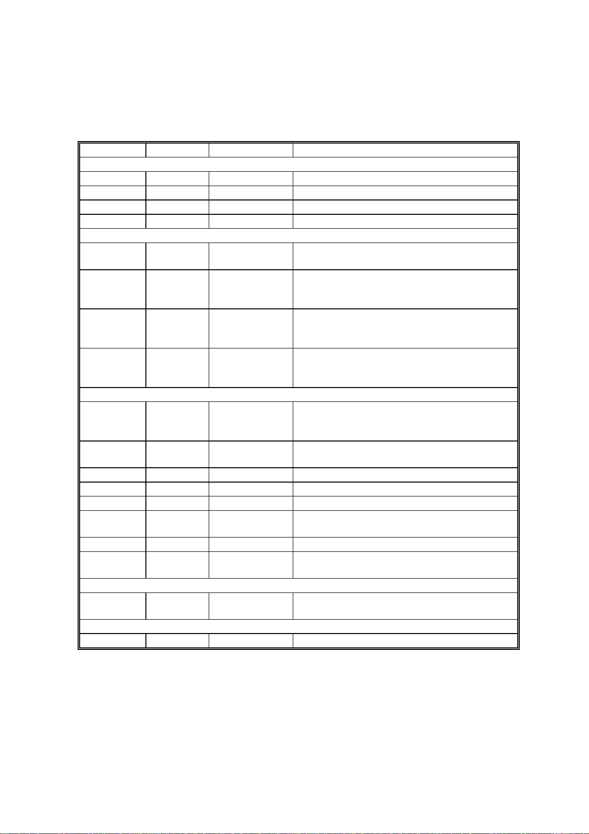
3.1.1 FACE-UP MODE
[D]
[C]
[E]
[A]
[B]
A849D001.WMF
A849D002.WMF
Copies exiting the copier pass through the entrance guide plate [A]. The entry roller
will send copies either to the inverter bin or to each bin, depending on the selected
mode.
When the sorter receives the feed-out s ignal from the main machine, th e entrance
motor and exit motor energize to rotate all the rollers in the sorter. During copying,
all rollers transport the paper at a speed that depends on the copier. When the
leading edge of the copy passes the entry sensor [B], the speed of the rollers
changes to 550 mm/s.
- 1st, 2nd and 3rd bins -
When the junction gate [C] is closed as sh own above, the copies pass through the
upper part of the junction gate. For 1st bin output mode, the copy goes straight up
from the junction gate directly to the bin. For the 2nd and 3rd bins, the copies from
the junction gate are delivered to these bins, as directed by the 2nd bin gate [D]
and 3rd bin gate [E].
Options
A849-5
Page 7
BASIC OPERATION 24 February, 1999
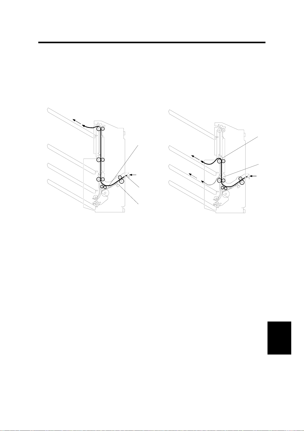
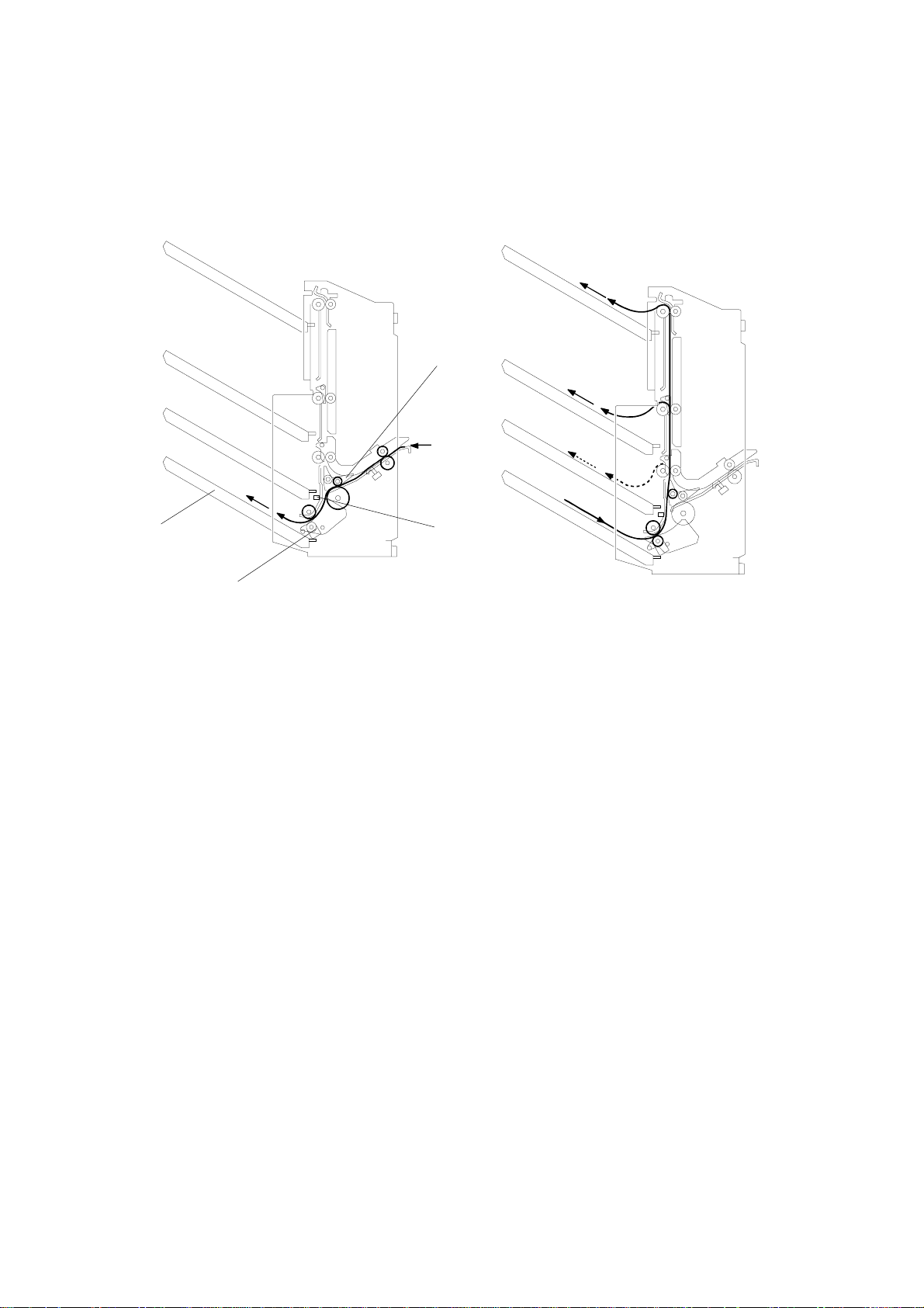
3.1.2 FACE-DOWN MODE
[A]
[B]
[D]
A849D003.WMF
[C]
A849D004.WMF
When the junction gate [A ] is opened, the copy goes to the inverter bin [B] through
the lower part of the junction. When the trailing edge of the copy passes through
the inverter sensor [C], the return pinch rollers [D] lower to contact the copy, then
the copy is fed back in by the rollers. The copy is fed out to any output bin and it
arrives face down.
A849-6
Page 8

24 February, 1999 1ST BIN UP/DOWN MECHANISM
3.2 1ST BIN UP/DOWN MECHANISM
[C]
[B]
[D]
[E]
[A]
A849D005.WMF
The tray lift motor (a dc motor) [A] controls the vertical position of the 1st bin [B]
through gears. When the main switch is turned on, the 1st bin is initialized at the
upper position. The bin's upper position is detected by the stack height sensor [C].
The 1st bin activates the stack height sensor, then the 1st bin lowers until it is at
the correct height to receive the copy. This initialization is performed before every
copy job.
During copying, when the stack of paper activates the stack height sensor, the 1st
bin lowers until the stack height sensor is deactivated.
When the 1st bin reaches its lower limit, actuator [D] enters the lower limit sensor
[E], and copying stops. After copying ends, the machine stops.
Options
A849-7
Page 9

1ST BIN SIDE-TO-SIDE SHIFT MECHANISM 24 February, 1999
3.3 1ST BIN SIDE-TO-SIDE SHIFT MECHANISM
[A]
[B]
[E]
A849D006.WMF
[B]
[E]
[G]
[F]
[C]
[D]
A849D007.WMF
In the sort/stack mode, the 1st bin [A] moves from side-to-side to s eparate the sets
of copies.
The tray shift motor (a DC motor) [B] and the shift cam [C] control the horizontal
position of the shift tray. After one set of copies is delivered to the bin, the tray shift
motor starts rotating, driving the shift cam through gears. The link [D] connected
between the shift cam and the tray shift plate [E] creates the side-to-side
movement required to separate the copy sets.
When the shift cam has rotated 180 degrees (when the tray is fully shifted across),
the tray half-turn sensor [F] is activated by the slot [G] in the actuator plate [H],
which is attached to the shift cam, and the tray shift motor stops. The next set of
copies is then delivered. The motor rotates, repeating the same process and
moving the bin back to the previous position.
A849-8
Page 10

24 February, 1999 PAPER FEED AND MISFEED DETECTION TIMING
3.4 PAPER FEED AND MISFEED DETECTION TIMING
— Normal Mode —
* 1
312 4560
(Sec.)
550 mm/s
J2
J1
J4
J4
J3
J3
300 mm/s 550 mm/s * 1
J3 J4
Normal Mode [A4 sideways, 3 pages, 40 CPM (200 mm/s)]
Feed Out Signal
Entrance Motor
Entry Sensor
*1: This speed depends on the copier.
Junction Gate Sol.
A849-9
3rd Exit Sensor
2nd Exit Sensor
1st Exit Sensor
A849D008.WMF
Exit Motor
Options
Page 11

PAPER FEED AND MISFEED DETECTION TIMING 24 February, 1999
— Inverter Mode —
* 1
312 4560
(Sec.)
550 mm/s
J7J6
J5
300 mm/s
J9
J9
J9
J8
J8
J8
550 mm/s
Inverter Mode [A4 sideways, 3 pages, 40 CPM (200 mm/s)]
Feed Out Signal
Entrance Motor
Entry Sensor
Junction Gate Sol.
*1: This speed depends on the copier.
Inverter Sensor
A849-10
Pinch Roller Sol.
1st Exit Sensor
Exit Motor
A849D009.WMF
2nd Exit Sensor
3rd Exit Sensor
Page 12

24 February, 1999 JAM DETECTION
3.5 JAM DETECTION
— Paper Jams —
J1: The entry sensor does not turn on within 2 s after the feed out signal has turned
on.
J2: The entry sensor does not turn off within 610 ms after the feed out signal has
turned off or the entry sensor stays on over 2.8 s.
J3: The following exit sensors do not turn on within the specified time after the entry
sensor has turned on.
1st exit sensor: 2.4 s
2nd exit sensor: 1.4 s
3rd exit sensor: 740 ms
J4: The following exit sensors do not turn off within the specified time after the entry
sensor has turned off.
1st exit sensor: 870 ms
2nd exit sensor: 500 ms
3rd exit sensor: 270 ms
J5: The inverter sensor does not turn off within 4.56 s after the inverter sensor has
turned on.
J6: The inverter sensor does not turn on again within 380 ms after the inverter
sensor has turned off.
J7: The inverter sensor does not turn off within 1.14 s after the inverter sensor has
turned on again.
J8: The following exit sensors do not turn on within the specified time after the
inverter sensor has turned on again.
1st exit sensor: 770 ms
2nd exit sensor: 430 ms
3rd exit sensor: 250 ms
J9: The following exit sensors do not turn off within the specified time after the
inverter sensor turned off again.
1st exit sensor: 770 ms
2nd exit sensor: 430 ms
3rd exit sensor: 250 ms
A849-11
Options
Page 13

EXTERIOR COVER AND BIN REMOVAL 24 February, 1999
4. REPLACEMENT AND ADJUSTMENT
4.1 EXTERIOR COVER AND BIN REMOVAL
[A]
[C]
[B]
[D]
1. Rear Cover [A] (3 screws)
2. Front Cover [B] (3 screws)
3. Top Cover [C] (2 screws)
4. Bins [D] (1st bin: 2 screws)
A849R006.WMF
A849-12
Page 14

24 February, 1999 TRAY LIFT/SHIFT MOTOR ASSEMBLY REMOVAL
4.2 TRAY LIFT/SHIFT MOTOR ASSEMBLY REMOVAL
[A]
[B]
A849R007.WMF
1. Remove the rear cover (see Exterior Cover and Bin Removal).
2. Remove the clip [A].
3. Remove the motor assembly [B] (3 screws, 3 connectors).
A849-13
Options
Page 15

ENTRANCE MOTOR REPLACEMENT 24 February, 1999
4.3 ENTRANCE MOTOR REPLACEMENT
[B]
[A]
A849R008.WMF
1. Remove the rear cover (see Exterior Cover and Bin Removal).
2. Remove the control board [A] (9 connectors, 4 clamps).
3. Remove the motor bracket [B] (2 screws).
4. Remove the exit motor [C] (2 screws).
[C]
A849R009.WMF
A849-14
Page 16

24 February, 1999 EXIT MOTOR REPLACEMENT
4.4 EXIT MOTOR REPLACEMENT
[B]
[A]
A849R010.WMF
1. Remove the rear cover (see Exterior Cover and Bin Removal).
2. Remove the motor bracket [A] (2 screws, 1 connector).
3. Remove the exit motor [B] (2 screws, 1 connector).
A849-15
Options
Page 17

STACK HEIGHT SENSOR AND 1ST EXIT SENSOR REPLACEMENT 24 February, 1999
4.5 STACK HEIGHT SENSOR AND 1ST EXIT SENSOR REPLACEMENT
[A]
A849R001.WMF
[C]
[B]
A849R002.WMF
1. Remove the front, rear, and top covers (see Exterior Cover and Bin Removal).
2. Remove all bins (see Exterior Cover and Bin Removal).
3. Remove the 3-bin sorter.
4. Remove the middle guide plate [A] (1 clip).
5. Remove the motor assembly [B] (see Tray Lift/Tray Shift Motor Assembly
Removal).
6. Remove the upper guide plate [C] (4 screws).
A849-16
Page 18

24 February, 1999 STACK HEIGHT SENSOR AND 1ST EXIT SENSOR REPLACEMENT
[D]
[E]
[F]
A849R003.WMF
7. Remove the middle shift guide plate [D] (3 screws).
8. Remove the stack height sensor [E] (1 connector).
9. Remove the 1st exit sensor [F] (1 screw, 1 connector).
A849-17
Options
Page 19

2ND / 3RD EXIT SENSOR AND INVERTER SENSOR REPLACEMENT24 February, 1999
4.6 2ND / 3RD EXIT SENSOR AND INVERTER SENSOR REPLACEMENT
[A]
[B]
[E]
[D]
[C]
A849R004.WMF
[G]
[F]
[H]
A849R005.WMF
1. Remove the front cover and rear cover (see Exterior Cover Removal).
2. Remove all bins.
3. Remove four tray brackets [A] (1 screw each).
4. Remove the upper exit cover [B] (2 screws).
5. Remove the lower exit cover [C] (2 screws).
6. Remove the sensor bracket [D] (1 screw) and replace the 2nd exit sensor [E] (1
screw, 1 connector).
7. Remove the sensor bracket [F] (1 screw) and replace the 3rd exit sensor [G] (1
screw, 1 connector).
8. Replace the inverter sensor [H] (1 screw, 1 connector).
A849-18
Page 20

млкйизжедмíìììëìêìéìèìç
$
кр%,1э6257(5эх$ейдфэ32,17э72э32,17э',$*5$0
&1êëí&1êêí
&1êéí
&1êìí
ðì
ðë
ðê
ðé
ðè
ðçðì
ðì
ðë
ðê
ðì
ðë
ðê
ðé
ðè
ðç
ðì
ðë
ðê
&1лднрл
ðê
ðë
ðì
ðê
ðë
ðì
ðê
ðë
ðì
ðì
ðë
ðê
ðì
ðë
ðê
ðì
&1ëèí&1ëèè&1ëçí&1ëçè&1ëæí&1ëæè&1ëåí&1ëåè
6ê
6ì
6é
6è
6ç
ìVWý([LWý6HQVRU
6WDFNý+HLJKW
6HQVRU
ëQGý([LWý6HQVRU
êUGý([LWý6HQVRU
,QYHUWHUý 6HQVRU
6RUWHUý6HWý6ZLWFK
6:ì
ðê
ðë
ðì
ðê
ðë
ðì
ðê
ðë
ðì
6ë
6å
6æ
7UD\ý +DOIð7XUQ
6HQVRU
7UD\ý/RZHUý/LPLW
6HQVRU
(QWU\ý6HQVRU
6<0%2/ý7$%/(
'&ý/LQH
3XOVHý6LJQDO
6LJQDOý'LUHFWLRQ
ýýýý ▼ $FWLYHý/RZ
эээээ▲ $FWLYHэ +LJK
ээ>эээээээ@ 9ROWDJH
0DLQý 0DFKLQH
%
>òèý9@
*1'
>òëéý9@
*1'
)ï*ï
î5;'ý>▼è@
î7;'ý>▼è@
7ì
&
(QWUDQFHý0RWRU
0ì
&1мннрм
&1ìèí
&1ìèí
&1мжнрм
'
ðæ
ðç
(
([LWý0RWRU
0ë
ðè
ðé
ðê
ðë
ðì
&1ëìí&1ëêè
ðì
ðë
ðê
ðé
ðè
ðç
ðæ
&1мднрм
ðë
ðê
ðé
ðë
ðê
ðé
ðè
ðç
ðæ
ðë
ðê
ðé
ðè
ðç
ðæ
>òèý9@
*1'
>òëéý9@
*1'
>▼è@ýî7;'
>▼è@ýî5;'
>òëéý9@
>òëéý9@
1&
>▼ëé@ý$
>▼ëé@ýî$
>▼ëé@ý%
>▼ëé@ýî%
>òëéý9@
>òëéý9@
1&
>▼ëé@ý$
>▼ëé@ýî$
>▼ëé@ý%
>▼ëé@ýî%
6WDFNý+HLJKWý>▲è@
&RQWUROý%RDUG
õ3&%ýìô
)
&1менрм
&1менрк
ðìí
>▼ëé@ýêUGý%LQý*DWH
ðë
>òëéý9@
>▼ëé@ý3LQFKý5ROOHU
ðé
>òëéý9@
ðè
1&
ðç
>▼ëé@ýëQGý%LQý*DWH
ðæ
>òëéý9@
ðå
1&
ðä
>òëéý9@
>▼ëé@ý-XQFWLRQý*DWH
7UD\ý+DOIð7XUQý>▲è@
7UD\ý/RZHUý/LPLWý>▲è@
&1ëêí&1ëêí&1ëëí
ðé
ðê
ðëðê
ðìðé
ðëðì
ðìðë
ðë
ðì
ðì
êUGý%LQý*DWHý6ROï
*
+
3LQFKý5ROOHUý6ROï
ëQGý%LQý*DWHý6ROï
-XQFWLRQý*DWHý6ROï
62/ë
62/é
62/ì
62/ê
ðë
ðì
ðë
,
ðë
7UD\ý6KLIWý0RWRU
-
7UD\ý/LIWý0RWRU
0ê
0é
ðì
ðë
ðì
&1ëéí
&1ëéè
ðë
ðì
ðë
ðì
&1мзнрм
&1мзнрк
>▲ëé@ý7UD\ý 6KLIWý 0RWRUýõòô
ðë
>í@ý 7UD\ý6KLIWý 0RWRUý õðô
>▲ëé@ý7UD\ý /LIWý 0RWRUýõòô
ðé
>▲ëé@ý7UD\ý /LIWý 0RWRUýõðô
>òèý9@
ìVWý([LWý>▲è@
*1'
>òèý9@
*1'
>òèý9@
ëQGý([LWý>▲è@
*1'
>òèý9@
êUGý([LWý>▲è@
*1'
>òèý9@
,QYHUWHUý>▲è@
*1'
*1'
6RUWHUý6HWý>▲è@
*1'
>òèý9@
*1'
>òèý9@
(QWU\ý>▼è@
*1'
>òèý9@
&1мкнрм
&1мкнрй
&1мкнрж
&1мйнрм
&1мйнрй
&1мйнрж
&1млнрм
1&
1&
ðìí
ðìì
ðç
ðè
ðë
ðé
ðê
ðê
ðë
ðè
ðç
ðê
ðë
ðå
ðì
ðä
ðç
ðë
ðè
ðê
ðé
ðê
ðè
ðë
ðç
ðì
ðå
ðë
ðê
ðé
ðè
ðç
ðæ
ðå
ðä
ðê
ðë
ðì
.
$
%
&
'
(
)
*
+
,
-
.
млкйизжедмíìììëìêìéìèìç
Page 21

3-BIN SORTER (A849) ELECTRICAL COMPONENTS
17
16
15
14
18
13
234
5
1
6
7
A849S001.WMF
8
101112
9
Index No. Description Symbol P-to-P
1 1st Exit S3 B13
2 Stack Height S1 B13
3 Sorter Set SW1 F13
4 2nd Bin Gate SOL1 H4
5 3rd Bin Gate SOL2 F4
6 Junction Gate SOL3 I4
7 Pinch Roller SOL4 G4
8 2nd Exit S4 C13
9 3rd Exit S5 E13
10 Inverter S6 E13
11 Entry S7 I13
12 Control PCB1 D9
13 Entrance M1 D4
14 Exit M2 E4
15 Tray Lower Limit S8 H13
16 Tray Lift M4 J4
17 Tray Half-Turn S2 H13
18 Tray Shift M3 J4
 Loading...