

Page 1

10-BIN SORTER
(Machine Code: A657)
Page 2
20 December 1996 SPECIFICATIONS
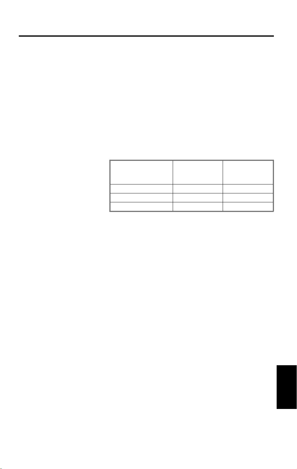
1. SPECIFICATIONS
Number of Bins: 10 bins
Paper Size for Bins: Sort/Stack Mode:
Maximum: A3, 11" x 17"
Minimum: A5, 5
1/2
Non-Sort/Stack Mode:
Maximum: A3, 11" x 17"
Minimum: A6 Lengthwise, 5
Paper Weight: Sort/Stack Mode: 64 to 90 g/m
Non-Sort/Stack Mode: 52 to 162 g/m
" x 8
1/2
"
1/2
" x 8
2
(17 to 24 lb)
1/2
"
2
(14 to 43 lb)
Bin Capacity:
1/2
A4, 8
B4, 8
A3, 11" x 17" 10 100
" x 11" or less 20 100
1/2
" x 14" 15 100
Sort/
Stack Mode
(All Bins)
Power Source: +5 volts and +24 volts from the copier
Power Consumption: 15 W
Dimensions (W x D x H): 402 mm x 447 mm x 217 mm
(15.7" x 17.5" x 8.5")
Weight: 7.5 kg (16.5 lb)
Non Sort/
Stack Mode
(Top Bin)
A657-1
Options
Page 3
COMPONENT LAYOUT 20 December 1996
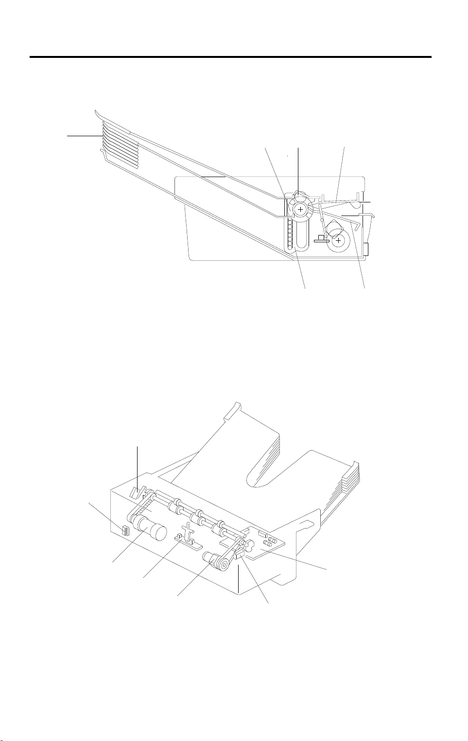
2. COMPONENT LAYOUT
- Mechanical Components -
1
1. Bins
2. Transfer Wheel
3. Exit Roller
- Electrical Components -
32 4
6 5
A657V500.wmf
4. Upper Paper Guide
5. Lower Paper Guide
6. Bin Guide
7
6
5
4
1. Sorter Main Board
2. Wheel Switch
3. Roller Drive Motor
4. Paper Sensor
1
3
2
A657V501.wmf
5. Bin Drive Motor
6. Sorter Switch
7. Bin Home Position Switch
A657-2
Page 4
20 December 1996 ELECTRICAL COMPONENT DESCRIPTIONS
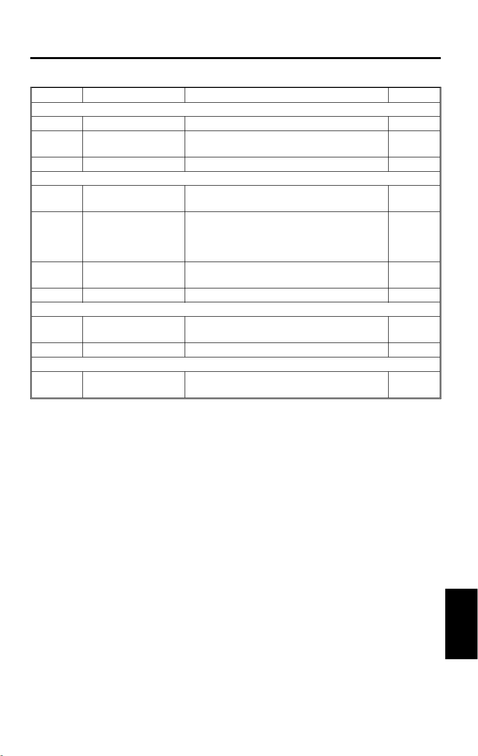
3. ELECTRICAL COMPONENT DESCRIPTIONS
Symbol
Motors
Switches
Sensors
Printed Circuit Boards
M1 Roller Drive Motor This dc motor drives the lower exit rollers. 3
M2
SW1
SW2
SW3
S1
PCB1
Bin Drive Motor This revers i bl e dc motor moves the bins up
Wheel Switch Detects the rotation of the transfer wheel and
Sorter Switch This reed switch becom es activated when
Bin Home Position
Switch
Paper Sensor Serves as the misfeed sensor for the sorter
Sorter Main Board Serves as the communication board between
Name Function Index No.
or down.
stops it in the correct position.
the sorter is in t he pr oper position (ali gned
next to the copier). It also works as a jam
reset switch for the sorter.
Informs the CPU th at a l l the b ins are lowered.
and also sets ex i t rol l er and bin drive tim i ng.
the copier mai n board and the sorter.
5
2
6
7
4
1
A657-3
Options
Page 5

BASIC OPERATION 20 December 1996
4. BASIC OPERATION
- Clear Mode -
When the main switch of the copier is turned on, the sorter automatically
assumes clear mode. In this mode, all copies are stacked in the first bin. The
sorter also assumes clear mode when interrupt mode is selected.
Sorter operation begins when the copier sends the paper feed signal to the
selected paper feed station. At this time, the roller drive motor energizes.
When the paper exits onto the sorter bin, the paper sensor is de-activated
and the roller drive motor is then de-energized. The copier main board
monitors the paper sensor through the sorter main board to check for paper
misfeeds.
- Sort Mode -
In this mode, all copies of the first original are delivered to separate bins
starting from the top. The copies of the second original are delivered to the
same bins, but starting from the bottom. The copies of the third original start
from the top and so on. At 400 milliseconds after the copy has gone through
the paper sensor, the bin drive motor turns on to advance the bins one step.
- Stack Mode -
In this mode, all copies of the first original are delivered to the first bin, all
copies of the second original are delivered to the second bin, and so on. At
400 milliseconds after the last copy of the original has gone through the
paper sensor, the bin drive motor turns on to advance the bins one step.
A657-4
Page 6
20 December 1996 EXIT ROLLER DRIVE MECHANISM
5. EXIT ROLLER DRIVE MECHANISM
[A]
[I]
[D]
[J]
[F]
[K]
[L]
[G]
[H]
[B]
[C]
A657D500.img
[H]
F: Transfer Wheel
G: Bin Drive Belt
H: B in Drive Pulley
I: Exit Roller Pulley
[E]
J: Upper Paper Guide
K: Lower Paper Guide
[L]
A657D501.wmf
L: Roller Drive Motor Pulley
The exit rollers [A] take over paper transport from the copier. When the copier
sends the paper feed signal to the selected paper feed station, the exit rollers
start rotating. The exit rollers continue to rotate for 900 milliseconds after the
copy paper has gone through the paper sensor [B].
The roller drive motor [C] rotates the lower exit roller via the roller drive belt
[D]. The shaft of the lower exit roller is a cylindrical cavity type which rotates
around the transfer wheel shaft [E]. The paper sensor is positioned just in
front of the exit rollers. The paper sensor detects misfeeds in the sorter.
Options
A657-5
Page 7

BIN DRIVE MECHANISM 20 December 1996
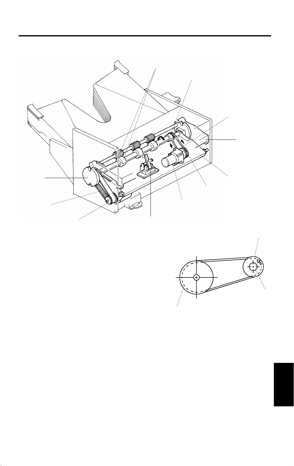
6. BIN DRIVE MECHANISM
[D’]
[E]
[B’]
[A]
[D]
[B]
[F]
G: Exit Roller
H: Upper P aper Guide
I: Lower Paper Guide
The bin drive mechanism moves the bins
up and down to receive copies under the
direction of the copier CPU. The main
components in this mechanism are the bin
drive motor [A], two transfer wheels [B,B’],
the wheel switch [C], and the bins themselves.
Pins on either side of each bin are inserted
into slots called bin guides [D,D’]. The bins
slide up and down in the bin guides.
The bins sit on each other with the lower bin
resting on the 10th bin (the 10th bin is
permanently fixed in position). The upper
and lower paper guides pivot up and down
depending on the height of the bin to be
picked up or released.
[G]
[B]
A657D502.img
[H]
[E]
[I]
A657-6
A657D503.img
Page 8

20 December 1996 BIN DRIVE MECHANISM
The bin home position switch [E] informs
the CPU when all the bins are lowered.
To move the bins up, the bin drive motor
turns clockwise (as viewed from the front).
A timing belt [F] turns the transfer wheels.
The transfer wheels have two slots in them
180 degrees apart. As the transfer wheels
turn, these slots engage the bins and lift
them up. Each time the transfer wheels turn
180 degrees, they raise one bin.
To move the bins down, the CPU reverses
the bin drive motor and the above
process reverses.
The CPU monitors the position of the bins
through pulses generated by the wheel
switch and the actuator cam [J].
The actuator cam has two flat sides that
are 180 degrees apart and is mounted
behind the rear transfer wheel. A pulse is
generated each time one of the lobes of
the actuator cam passes the wheel switch.
[B]
[J]
[C]
A657D504.wmf
Options
A657-7
Page 9

MISFEED DETECTION 20 December 1996 SERVICE TABLES
7. MISFEED DETECTION
A657D505.wmf
In addition to being used for the exit roller drive timing, the paper sensor
checks for misfeeds in the sorter.
J1 - Paper Sensor On Check (A4 Sideways):
The copier CPU checks whether the paper sensor is actuated within 4.32
seconds after the registration clutch turns on.
J2 - Paper Sensor Off Check (A4 Sideways):
The copier CPU also starts a timing cycle to detect the paper sensor off
check after the registration clutch turns on. The misfeed detection timing is
6.71 seconds.
In misfeed condition, the "Check Paper Path" and "Misfeed Location"
indicators light and copier operation is disabled. To recover the sorter from
the misfeed condition, the sorter has to be slid away from the copier, the
misfed paper removed, and the sorter returned to its original position.
8. SERVICE TABLES
8.1 FUSE
Fuse No. Rating Blown Fuse Condition
F101 T1.0 A/250 V Sorter will not operate.
F102 T0.5 A/250 V Sorter will not operate.
A657-8
Page 10
20 December 1996 PREPARATION FOR TRANSPORTATION
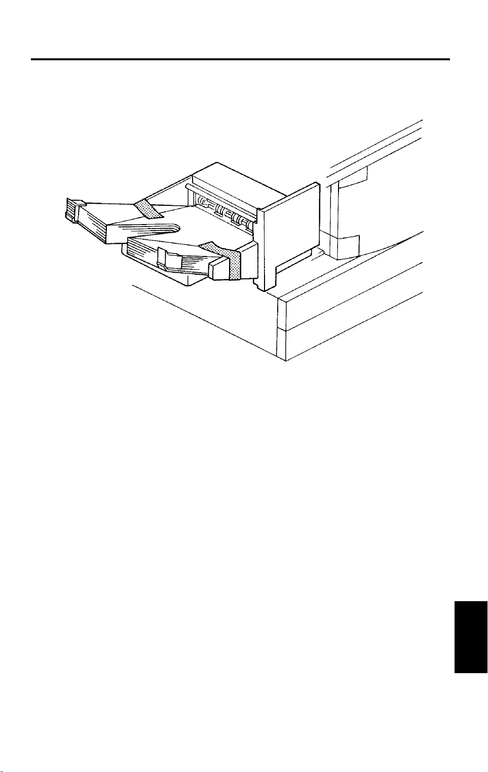
9. PREPARATION FOR TRANSPORTATION
A657R500.img
CAUTION:
When removing and transporting the sorter, be careful not to
carry it in a vertical position, as the bins will become dislocated.
CAUTION:
Before moving the sorter, be sure to prepare it for transportation
as follows. The sorter may be badly damaged if it is moved
without proper preparation.
1. If the bins are not at the home position, turn on the main switch of the
copier to move the bins to the home position.
2. Secure the bins with strips of tape as shown in the illustration.
3. Remove the sorter from the copier. (See the Installation Procedure.)
Options
A657-9
Page 11

ROLLER DRIVE BELT REPLACEMENT 20 December 1996
10. ROLLER DRIVE BELT REPLACEMENT
[M]
[K]
[N]
[L]
[I]
[E]
[F]
[H]
[D]
[G]
[A]
A657R501.img
[C]
[B]
A657R502.img
A657R503.wmf
1. Remove the front cover [A] (1 screw).
2. Remove the rear cover [B] (1 screw) and the sorter hinge [C] (2 screws).
3. Remove the rear flat cover [D] (2 screws).
4. Lift off the top cover [E].
5. Lift the upper paper guide [F] up and out of position (1 grounding wire).
6. Remove the entrance guide bracket [G] (2 screws).
7. Lift the lower paper guide [H] out of position and turn it over to remove the
roller drive belt [I].
NOTE:
Be careful not to damage the bin home position switch actuator
[J] when reassembling.
8. Remove the transfer spacer [K], wheel [L], pin [M], and bushing [N] on
both sides of the shaft.
9. Slide the wheel shaft towards the front and replace the roller drive belt.
A657-10
Page 12

20 December 1996 BIN GUIDE LUBRICATION
11. BIN GUIDE LUBRICATION
A
B
C
A
B
C
A
B
C
A
B
C
Grease 501
[A]
Grease 50 1
[B]
[B]
A657R504.img
1. Remove the lower paper guide. (See Roller Drive Belt Replacement.)
2. Remove all bins [A] from the bin guides [B].
3. Apply G501 grease to the grooves of the bin guides.
NOTE:
There are three types of bins (types A, B, and C in the above
diagram). Therefore, when installing the bins, be sure that they
are installed in the correct order.
Options
A657-11
Page 13

SORTER (A657) 20 December 1996
4.SORTER INSTALLATION (A657)
4.1ACCESSORY CHECK
Check the accessories against the following list:
Description Q’ty
1. Holder Bracket.................................................................. 1
2. Magnet Catch................................................................... 1
3. Tapping Screw M4 x 6...................................................... 6
4. Grounding Screw M4 x 8.................................................. 1
5. Snap Ring......................................................................... 1
6. NECR - Multi-language..................................................... 1
7. Installation Procedure - English........................................ 1
3-12
Page 14
20 December 1996 SORTER (A657)
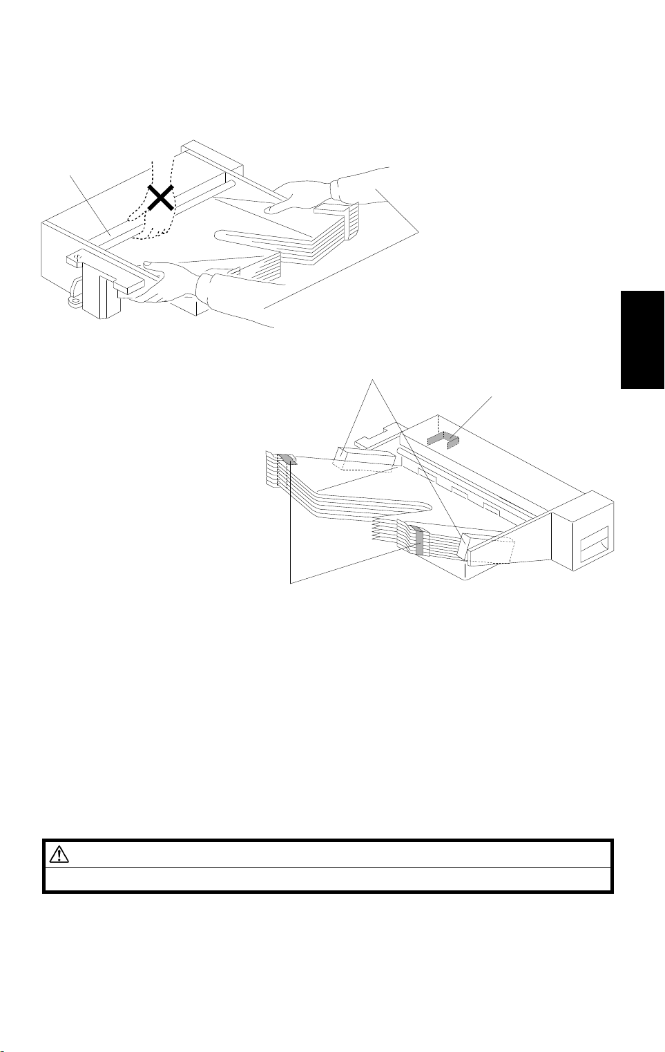
4.2 INSTALLATION PROCEDURE
[A]
[C]
[B]
NOTE:
A657I500.wmf
[E]
[D]
[D]
A657I501.wmf
1) Keep the shipping retainers after installing the machine. They will
be reused if the machine will be transported to an another location
in the future.
2) Proper installation of the shipping retainers is required in order to
avoid any transport damage.
Installation
3) Do not grasp the sorter by the top cover and stay as shown by [A].
Hold both sides of the sorter as shown by [B]. This is to prevent
damage to the anti-static brush [C].
CAUTION
Unplug the copier power cord before star ting the follo wing procedure.
1. Remove the copy tray from the copier.
2. Remove the strips of tape [D] and styrofoam blocks [E].
3-13
Page 15

SORTER (A657) 20 December 1996
[A]
[B]
[D]
A657I502.wmf
[C]
A657I503.wmf
3. Remove the 2 portions [A] on the left hand side of the copier with cutting
pliers as shown.
4. Remove the rear cover [B] (2 screws).
5. Mount the sorter holder bracket [C] on the copier frame (3 tapping
screws).
6. Mount the magnetic catch [D] near the exit cover (2 tapping screws).
3-14
Page 16

20 December 1996 SORTER (A657)
[B]
[E]
[C]
[D]
[F]
[G]
[A]
A657I504.wmf
Installation
7. Install the sorter [A] on the sorter holder bracket [B] (1 snap ring) as
shown.
8. Insert the sorter harness [C] and the grounding wire [D] through the
opening in the lower left cover. Plug the connector in to CN130 [E] on the
main control board, and secure the grounding wire to the copier frame [F]
(1 M4 x 8 sc rew).
9. Secure the bracket [G] (1 tapping screw).
10. Reinstall the rear cover.
11. Plug in the copier power cord and turn on the main switch.
12. Enter SP mode as follows:
1) Press the
2) Enter "107" using the numeric keys.
3) Hold down the
13. Press the following sequence of keys to change the "SP 71" value to "1".
→
9
3
→
key.
key for more than 3 seconds.
→ 3 →
14. Turn the main switch off and on.
15. Check the sorter’s operation.
3-15
Page 17

SORTER (A657) ELECTRICAL COMPONENT LAYOUT
7
6
5
4
3
Description Index No. P to P Location
Sorter Main Board (PCB1) 1 G1
Wheel Switch (SW1) 2 H2
Roller Drive Motor (M1) 3 H1
Paper Sensor (S1) 4 H2
Bin Drive Motor (M2) 5 H1
Sorter Switch (SW2) 6 H2
Home Position Switch (SW3) 7 H1
2
A657S500.wmf
1
 Loading...