

Page 1

10-BIN SORTER
(MICRO - α)
(Machine Code: A557)
Page 2

13th January 1995 SPECIFICATIONS
1. SPECIFICATIONS
Number of Bins: 10 bins
Paper Size for Bins: Sort/Stack Mode
Maximum - A3, 11" x 17"
Minimum - A5, 51/2" x 81/2"
Paper Weight: Sort/Stack Mode: 64 to 90 g/m2 (17 to 24 lb)
Non-Sort/Stack Mode: 52 to 162 g/m2 (14 to 43 lb)
Bin Capacity:
Sort/Stack Mode
(All Bins)
A4, 8
1/2" x 11"
or less
1/2" x 14" 15 100
B4, 8
A3, 11" x 17" 10 100
20 100
Non Sort/Stack Mode
(Top Bin)
Power Source: +5 volts and +24 volts from the copie r
Power Consumption: 15 W
Dimensions:
(W x D x H)
402 mm x 455 mm x 217 mm
(15.7" x 17.8" x 16.7")
Weight: 7.5 kg (16.5 lb)
)
α
(MICRO -
10-bin Sorter
1
Page 3
[2]
COMPONENT LAYOUT 13th January 1995
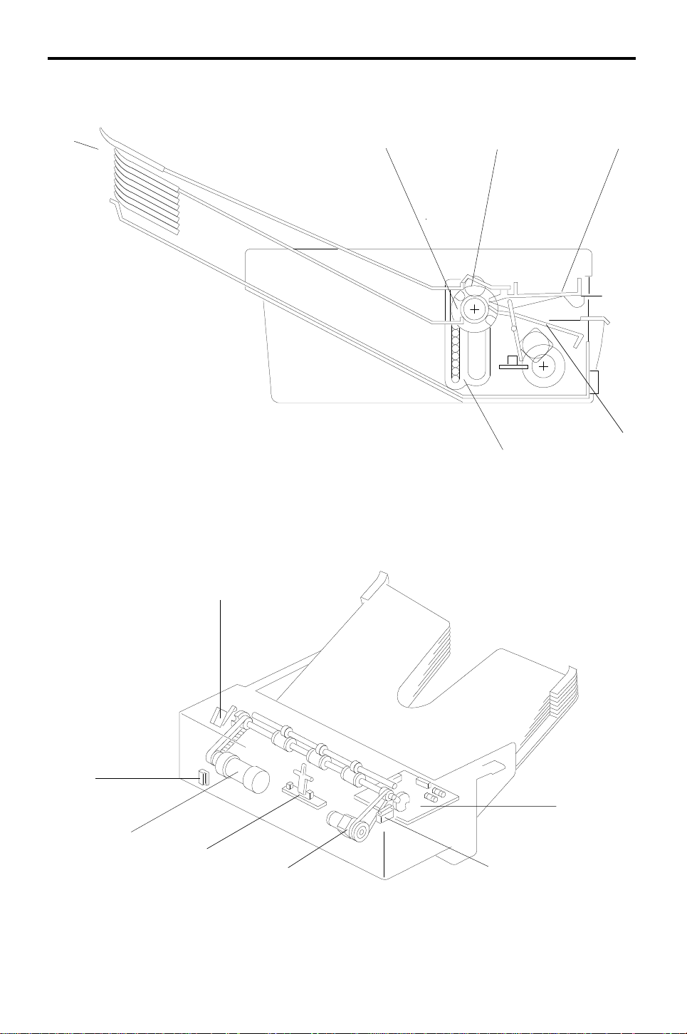
2. COMPONENT LAYOUT
— Mechanical Components —
[1]
1. Bins
2. Transfer Wheel
3. Exit Roller
4. Upper Paper Guide
5. Lower Paper Guide
6. Bin Guide
[3]
[6]
[4]
[5]
— Electrical Components —
[6]
[5]
1. Sorter Main Board 5. Bin Drive Motor
2. Wheel Switch 6. Sorter Switch
3. Roller Drive Motor 7. Bin Home Position Switch
4. Paper Sensor
[7]
[4]
[3]
[1]
[2]
2
Page 4
13th January 1995 ELECTRICAL COMPONENT DESCRIPTIONS
3. ELECTRICAL COMPONENT DESCRIPTIONS
Symbol Name Function Index No.
Motors
M1 Roller Drive Motor This dc motor drives the lower exit rollers. 3
M2 Bin Drive Motor
Switches
SW1 Wheel Switch
SW2 Sorter Switch
SW3
Sensors
S1 Paper Sensor
Printed Circuit Boards
PCB1 Sorter Main Board
Bin Home Position
Switch
This reversible dc motor moves the bins up
or down.
Detects the rotation of the transfer wheel
and stops it in the correct position.
This reed switch becomes activated when
the sorter is in the proper position (aligned
next to the copier). It also works as a jam
reset switch for the sorter.
Informs the CPU that all the bins are
lowered.
Serves as the misfeed sensor for the sorter
and also sets exit roller and bin drive timing.
Serves as the communication board
between the copier main board and the
sorter.
5
2
6
7
4
1
)
α
(MICRO -
10-bin Sorter
3
Page 5

BASIC OPERATION 13th January 1995
4. BASIC OPERATION
- Clear Mode -
When the main switch of the copier is turned on, the sorter automatically
assumes clear mode. In this mode, all copie s are stacked in the first bin. The
sorter also assumes clear mode when int errupt mode is selected.
Sorter operation beg ins when the copier sends th e pape r f ee d sign al to the
selected paper feed statio n. At th is time, the roller drive motor energize s.
When the paper exits onto the sorter bin, the paper sen sor is d e-a ctiva te d
and the roller drive motor is then de-en erg ized. The copier main board
monitors the paper sensor through the sorter main board to che ck for pa per
misfeeds.
- Sort Mode -
In this mode, all copies of the first original are delivered to separate bins
starting from the top . The copies of the second original are delivered to the
same bins, but starting from th e bottom. The copies of the third origin al sta rt
from the top and so on. At 250 milliseconds after th e cop y has go ne thro ug h
the paper sensor, the bin drive motor turns on to advan ce th e bin one st ep.
- Stack Mode -
In this mode, all copies of the first original are delivered to the first bin, all
copies of the second origina l a re de livere d to the secon d bin, and so on. At
250 milliseconds after the last copy of the origin al ha s gone th rou gh the
paper sensor, the bin drive motor turns on to advan ce th e bin one step .
4
Page 6
[B]
13th January 1995 EXIT ROLLER DRIVE MECHANISM
5. EXIT ROLLER DRIVE MECHANISM
[A]
[I]
[D]
[J]
[F]
[K]
[L]
[C]
[G]
[H]
[H]
F: Transfer Wheel
G: Bin Drive Belt
H: B in Drive Pulley
[E]
I: Exit Roller Pulley
J: Upper Paper Guide
[L]
K: Lower Paper Guide
L: Roller Drive Motor Pulley
The exit rollers [A] take over paper tran sport from the copier. When the cop ier
sends the paper feed sign al to the selected paper feed station, the exit rollers
start rotating. The exit rolle rs cont inu e to rota te for 250 milliseco nd s aft er th e
copy paper has gone throu gh the pap er sensor [B].
)
α
(MICRO -
10-bin Sorter
The roller drive motor [C] rotates the lower exit roller via the roller drive belt
[D]. The shaft of the lower exit roller is a cylindrical cavity type which rotates
around the transfer wheel shaft [E]. The pap er sensor is positioned just in
front of the exit rollers. The paper senso r det ects misfeeds in the sorter.
5
Page 7

BIN DRIVE MECHANISM 13th January 1995
6. BIN DRIVE MECHANISM
[E]
[D]
[B]
G : Exit Roller
H : Upper Paper Guide
I : Lower Paper Guid e
[F]
[A]
[A]
[C]
[G]
[E]
[D’]
[B’]
[H]
The bin drive mechanism moves the bins up
and down to receive copies und er the
direction of the copier CPU. The main
components in this mechanism are the bin
drive motor [A], two transfer wheels [B,B’],
the wheel switch [C], and the bins
themselves.
Pins on either side of each bin are inserted
into slots called bin guides [D,D’]. The bins
slide up and down in the bin guides. The
bins sit on each other with the lower bin
resting on the 10th bin (th e 10 th bin is
permanently fixed in position). The upper
and lower paper guides pivot up an d do wn
depending on th e height of the bin to be
picked up or released.
[I]
[B]
6
Page 8

13th January 1995 BIN DRIVE MECHANISM
The bin home position switch [E] informs
the CPU when all the bins are lowered.
To move the bins up, the bin drive mot or
turns clockwise (as viewed from the
front). A timing belt [F] turns the tran sfe r
wheels.
The transfer wheels have two slots in
them 180 degrees apart . As th e transfer
wheels turn, these slots e ngag e th e bins
and lift them up. Each time the transf er
wheels turn 180 degrees, the y ra ise on e
bin.
To move the bins down, the CPU
reverses the bin drive motor and the
above processes reverses.
The CPU monitors the position of the
bins through pulses generated by the
wheel switch and the actuator cam [J].
The actuator cam has two flat side s tha t
are 180 degrees apart and is mounted
behind the rear transfer wheel. A pu lse
is generated each time one of the lobes
of the actuator cam passes th e wheel
switch.
[B]
[J]
[C]
)
α
(MICRO -
10-bin Sorter
7
Page 9

MISFEED DETECTION 13th January 1995
7. MISFEED DETECTION
In addition to being used for the exit roller drive timing, the paper sen sor
checks for misfeeds in the sorter.
J1 - Paper Sensor On Check: The copier CPU checks whether the paper
sensor is actuated within 942 pulses (3.8 seconds) after the registration
clutch turns on (at 2,000 pulses).
J2 - Paper Sensor Off Check: The copier CPU starts a timing cycle when
the paper sensor is actuated. Then, at 2.75 (A4 sidewa ys) o r 2.8 0 (Letter
sideways) seconds, the CPU checks whet he r the copy pa per has pa ssed
through the paper sensor.
In misfeed condition , th e "Check Paper Path" and "Misfe ed Loca tio n"
indicators light and copier operation is disabled. To recover the sorter from
the misfeed condition, the sorte r has to be slid away from th e cop ier, the
misfed paper removed, and the sorte r re tu rned to its original position.
8
Page 10

13th January 1995 INSTALLATION
8. INSTALLATION
8.1 ACCESSORY CHECK
Check the quantity and condition of the accessorie s in the box against the
following list:
1. Magnet Catch .................. .......... .......... .................. ........1
2. Sorter Holder Bracket .................................................. 1
3. Tapping Screw - M4 x 6................................. .......... ...... 3
4. Tapping Screw - M4 x 8................................. .......... ...... 2
5. Snap Ring...................................................................... 1
6. Installation Procedure.................................................... 1
7. New Equipment Condition Report....... .. .. .. .. .. .. .. ............1
)
α
(MICRO -
10-bin Sorter
9
Page 11

INSTALLATION 13th January 1995
8.2 INSTALLATION PROCEDURE
[C]
[A]
[F]
[B]
[D]
[E]
[D]
NOTE: (1) Keep the shipping retainers after in sta lling the machine. They will
be reused if the machine will be transported to an another
location in the future.
(2) Proper installatio n of the shipping retainers is require d in ord er to
avoid any transport damage.
(3) Do not grasp the sorter by the top cover and stay as shown by
[A]. Hold both sides of th e sort er as shown by [B]. This is to
prevent damage to th e an ti-st atic brush [C].
CAUTION
!
Unplug the copier power cord before starting the following procedure.
1. Remove the strips of tape [D] and styrofoam blocks [E].
2. Remove the copy tray [F] .
10
Page 12

[A]
13th January 1995 INSTALLATION
[B]
[C]
[D]
3. Remove the cover plat e [A ] (2 screws).
4. Cut the links in the cover plate [A] with nippers to remove th e smaller part
[B].
5. Remount the cover plate [A] (1 screw).
6. Mount the sorter holder bra cket [C] (3 tapping screws) on the cop ier
frame as shown.
7. Mount the magnetic catch [D] on the exit cove r (2 self-t ap pin g screws).
)
α
(MICRO -
10-bin Sorter
11
Page 13

[A]
INSTALLATION 13th January 1995
[B]
[D]
[C]
8. Install the sorter [ A] on th e sorter holder bracket [B] (1 snap ring) as
shown.
9. Connect the conne cto r [ C] to the socket [D] on the rear side of the cop ier.
10. Plug in the copier power cord and turn on th e main swit ch.
11. Press the following sequence of keys to enter SP mode.
→→→
NOTE:
(1) Hold the last key for more than 3 seconds.
(2) Upon entering SP mode, "1" blin ks in the 3rd dig it of the copy
counter, the Auto Im ag e Density indicator starts blin king and
the reduce/enlarg e ind icator turns off.
(3) The above procedure must be fin ished within 20 seconds.
12. Press the following sequence of keys to change th e "SP6-101" value t o "1".
→ → → → →
→ →
13. Turn the main switch off and on.
14. Check the sorter’s operation.
12
Page 14

13th January 1995 PREPARATION FOR TRANSPORTATION
9. PREPARATION FOR TRANSPORTATION
CAUTION
!
When removing and transporting the sorter, be careful not to carry it
in a vertical position as the bins wil l bec ome dislocated.
CAUTION
!
Refore moving the sorter, be sure to prepar e it for tra nspor tati on a s
follows. The sorter may be badly damage d if i t is mov ed wi thout
proper preparation.
1. If the bins are not at the home position, turn on the main switch of the
copier to move the bins to the home position.
2. Secure the bins with strips of tape as sho wn in th e illust ration.
3. Remove the sorter from the copier. (See the Insta llat ion Procedure.)
)
α
(MICRO -
10-bin Sorter
13
Page 15

[J]
[B]
ROLLER DRIVE BELT REPLACEMENT 13th January 1995
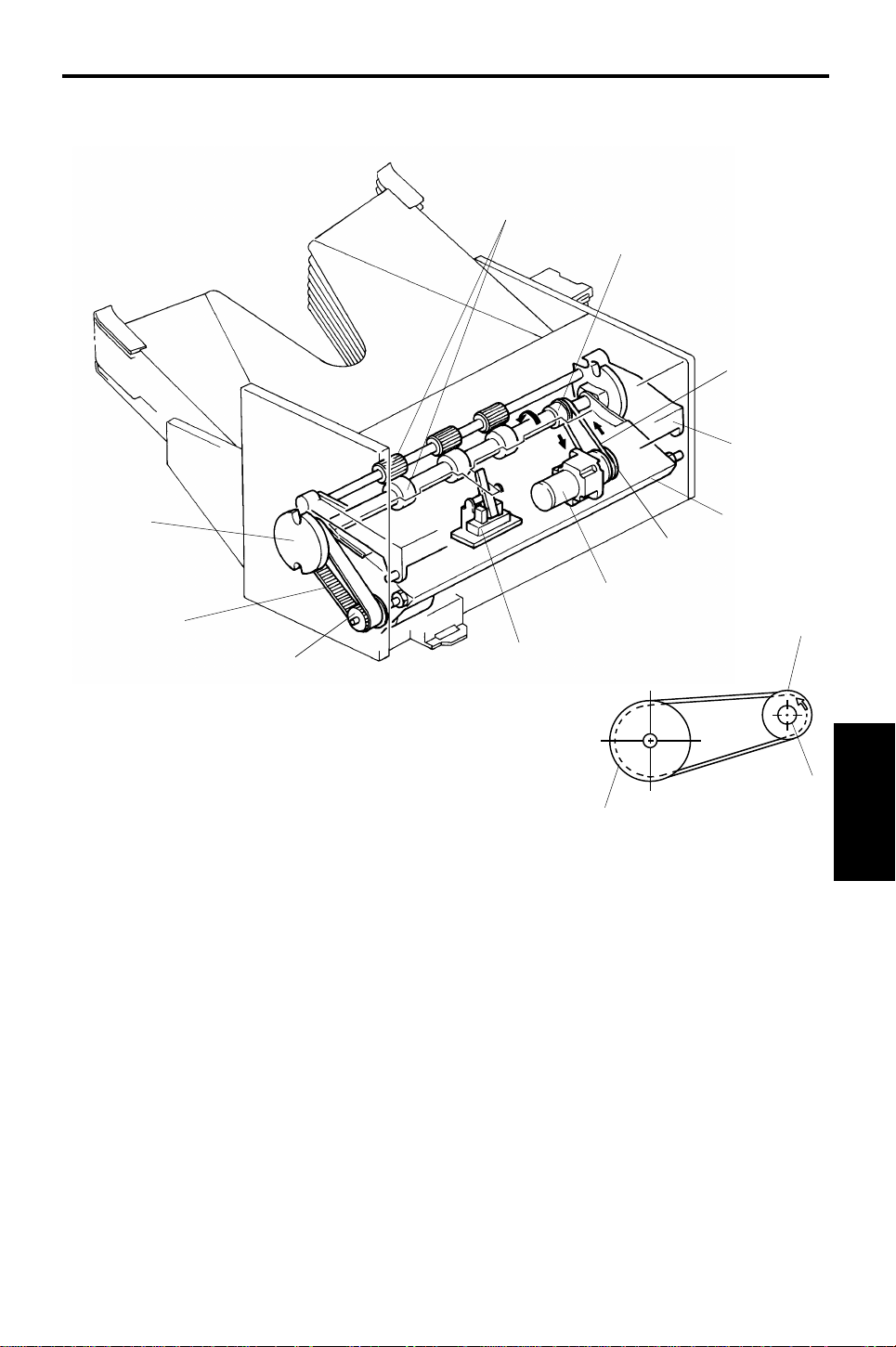
10. ROLLER DRIVE BELT REPLACEMENT
[M]
[N]
[K]
[L]
[I]
[D]
[F]
[H]
[E]
[G]
[A]
[C]
1. Remove the front cover [A] (1 screw).
2. Remove the rear cover [B] (1 screw) and the sorter hinge [C] (2 screws).
3. Remove the rear flat cover [D] (2 screws).
4. Lift off the to p cover [E].
5. Lift the upper paper guide [F] up and out of positio n (1 gro unding wire).
6. Remove the entrance guide bracket [G] (2 screws).
7. Lift the lower paper gu ide [H] out of position and turn it over to remove the
roller drive belt [I].
NOTE: Be careful not to damag e th e bin home position switch act ua to r
[J] when reassembling.
8. Remove the transfer spacer [K], wheel [L] , pin [M], and bushing [N] on
both sides of the shaft.
9. Slide the wheel shaft towa rds th e fro nt and repla ce th e rolle r drive be lt.
14
Page 16

13th January 1995 BIN GUIDE LUBRICATION
11. BIN GUIDE LUBRICATION
A
B
C
A
B
C
B
C
B
C
B
C
[B]
Grease 501
Grease 501
[B]
[A]
)
α
1. Remove the lower paper guide . (Se e Roller Drive Belt Replacement .)
2. Remove all bins [A] from the bin guid es [B ].
3. Apply Grease 501 to the grooves of the bin guides.
NOTE: There are three types of bins (types A, B, and C in the above
diagram). Therefore, when installing the bins, be sure that they
are installed in the correct ord er.
15
(MICRO -
10-bin Sorter
Page 17

 Loading...