

Page 1

1. SPECIFICATIONS
1 August 1988
Number of Bins:
Paper Size for Bins:
Paper Weight:
Bin Capacity:
Top Bin Capacity:
(Non-Sort/Stack Mode)
Power Source:
Power Consumption:
Dimensions:
(WxDxH)
Weight:
10 bins
Maximum
Minimum
A3, 11"x 17"
A6, 5½"
x 8½"
(Lengthwise)
64
to
90
g/m² (17 to 24 lb)
Sort/Stack
Mode 15 sheets/ B4,
20 sheets/ A4,
8½"
8½"
x11"
x 14"
10 sheets/ A3, 11" x 17"
100 sheets (all sizes)
+ 5 volts and +24 volts from the copier
7.7
W
440 mm x 391 mm x 367 mm
(1 7.3" x 15.4" x 14.4")
7.5 kg (16.5 lb).
9-1
Page 2
1 August 1988
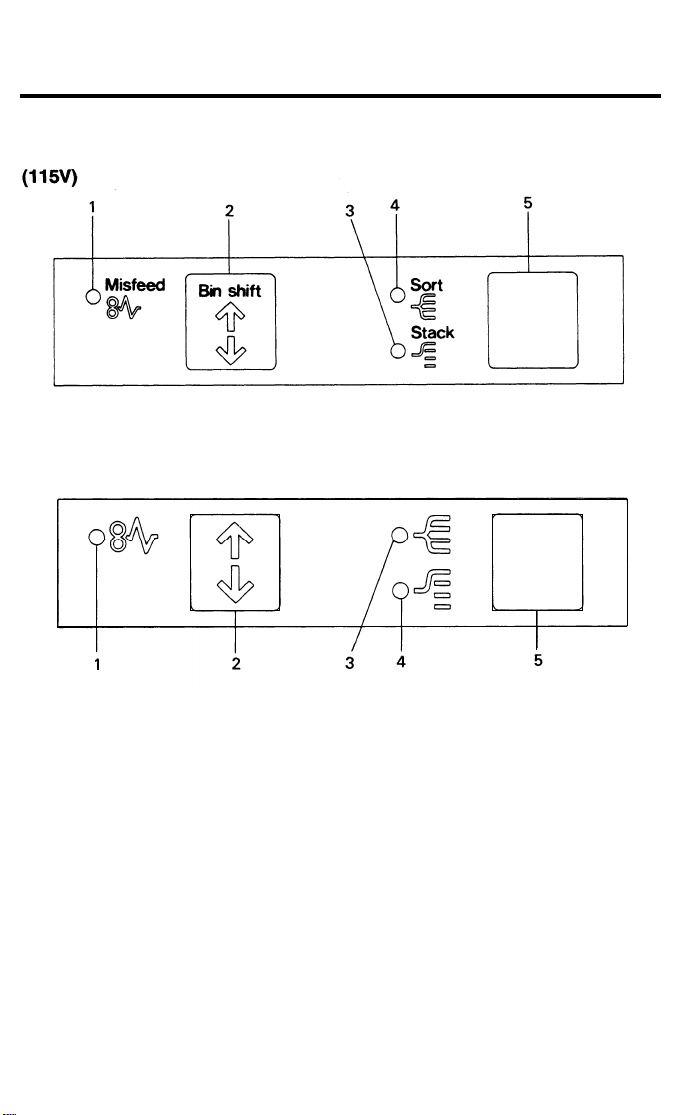
2. OPERATION PANEL
(220/240V)
1. Check Sorter Paper Path
Indicator
2. Bin Shift Key
3. Stack Indicator
4. Sort Indicator
5. Sorter Key
Lights when there is a paper misfeed in the
sorter.
Press to shift the bins. Use this key to
remove jammed paper.
Lights when copies from different copy runs
are to be grouped into individual stacks.
Lights when sets of copies are to be assembled in order.
Press to select sort and stack modes or to
turn off the sorter (clear mode).
9-2
Page 3
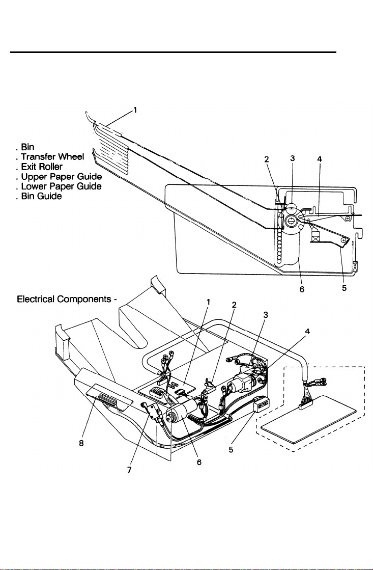
3. COMPONENT LAYOUT
- Mechanical Components -
1
2
3
4
5
6
1 August 1988
1. Sorter Main Board
2. Paper Sensor
3. Wheel Switch
4. Roller Drive Motor
5. Sorter Switch
6. Bin Drive Motor
7. Home Position Switch
8. Operation Panel Board
9-3
Page 4

1 August 1988
4. ELECTRICAL COMPONENT
Symbol Name
Motors
M1
M2 Bin Drive Motor
Roller Drive Motor
Switches
SW1
SW2
SW3
Wheel Switch
Sorter Switch
Home Position
Switch
Sensors
S1
Paper Sensor
Printed Circuit Boards
PCB1
PCB2
Sorter Main Board
Operation Panel
Board
DC motor that energizes to drive the lower
exit rollers.
Reversible DC motor that energizes to move
the bins up or down.
Detects the rotation of the transfer wheel
and steps it in the correct position.
Read switch that becomes activated when
the sorter is in the proper position (aligned
next to the copier). Also works as a jam
reset switch for the setter.
Informs the CPU that all the bins are
lowered.
Serves as the misfeed sensor for the sorter
and also sets exit roller and bin drive timing.
Serves as the communication board between the copier main board and the sorter.
Contains the Sorter key and Sorter Misfeed
indicators.
Function
DESCRIPTIONS
Location
4
6
3
5
7
2
1
8
9-4
Page 5
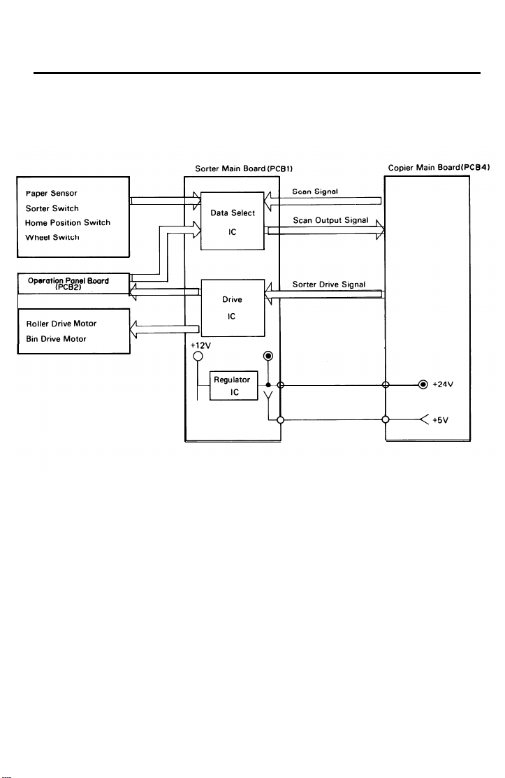
5. OVERALL MACHINE CONTROL
1 August 1988
The copier main board provides the sorter main board with +24 volts and
+5 volts. +24 volts powers the roller drive motor and the indicator LEDs on
the operation panel board, and +5 volts powers all sensors and switches.
Also, +24 volts is changed to +12 volts by the regulator IC, which powers
the bin drive motor.
The copier main board controls the drive and checks the status of the sorter
via the sorter main board. The copier main board sends the scan signal to
the data select IC on the sorter main board. After receiving the scan signals,
the data select IC outputs the status of the sensor, switches, or keys as the
scan output signal.
The copier main board also sends the sorter drive signal. After receiving the
drive signals, the drive IC turns on the appropriate motors and operation
panel indicators.
9-5
Page 6

1 August 1988
6. BASIC OPERATION
- Clear Mode -
When the main switch of the copier is turned on, the sorter automatically as-
sumes the clear mode. In this mode, all copies are stacked on the first bin.
The sorter also assumes the clear mode when either the interrupt mode or
the manual feed mode is selected.
Sorter operation begins when a copy actuates the copier exit sensor. At this
time, the roller drive motor energizes. When the paper exits onto the sorter
bin, the paper sensor is de-activated and the roller drive motor is then de-
energized.
sorter main board to check for paper misfeeds.
- Sort Mode -
Pressing the Sorter key once shifts the copier to the sort mode. In this mode,
all copies of the first original are delivered to separate bins starting from the
top. The copies of the second original are delivered to the same bins, but
starting from the bottom. The copies of the third original start from the top
and so on. The bin drive motor turns on to advance the bin one step, 250
milliseconds after the copy has gone through the paper sensor. If the Copy
Quantity, Clear/Stop, Book Copy, or Sorter key is pressed during the sort
mode, all bins shift to the home position.
The copier main board monitors the paper sensor through the
- Stack Mode Pressing the Sorter key twice shifts the copier to the stack mode. In this
mode, all copies of the first original are delivered to the first bin, all copies of
the second original are delivered to the second bin, and so on. The bin drive
motor turns on to advance the bin one step, 250 milliseconds after the last
copy of the original has gone through the paper sensor. If the Sorter key is
pressed during stack mode, all bins shift to home position.
9-6
Page 7
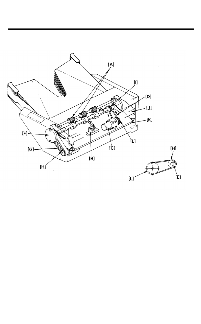
7. EXIT ROLLER DRIVE
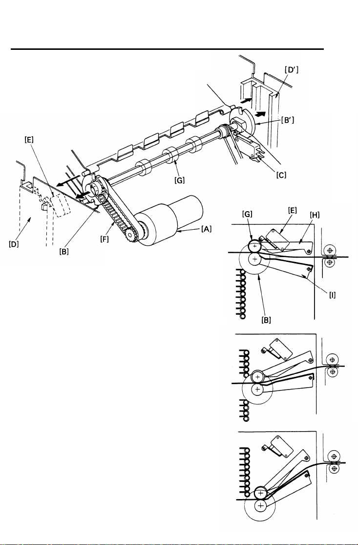
7.1 Roller Drive Mechanism
1 August 1988
F:
G:
H:
I:
J:
K:
L:
The exit rollers [A] take over paper transport from the copier. When the copy
paper actuates the copier exit sensor, the exit rollers start rotating. The exit
rollers continue to rotate for 250 milliseconds after the copy paper has gone
through the paper sensor [B].
The roller drive motor [C] rotates the lower exit roller via the roller drive belt
[D]. The shaft of the lower exit roller is a cylindrical cavity type which rotates
around the transfer wheel shaft [E]. The paper sensor is positioned just in
front of the exit rollers. The paper sensor detects misfeeds in the sorter.
Transfer Wheel
Bin Drive Belt
Bin Drive Pulley
Exit Roller Pulley
Upper Paper Guide
Lower Paper Guide
Roller Drive Motor Pulley
9-7
Page 8
1 August 1988
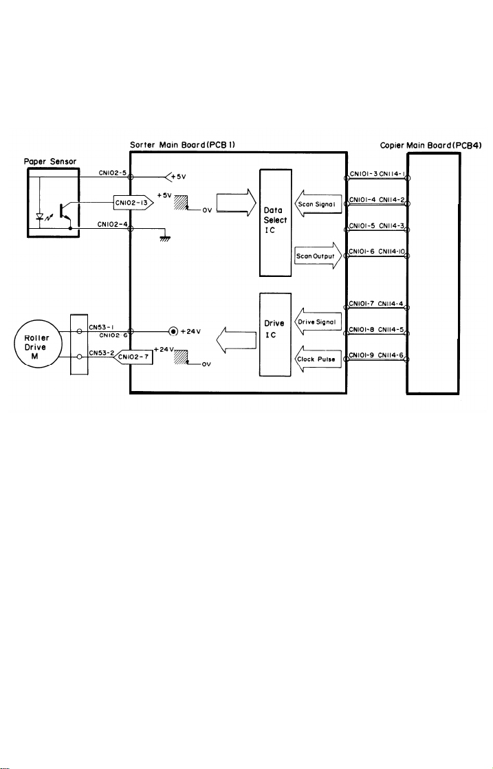
7.2 Roller Drive Circuit
To turn on the roller drive motor, the copier main board sends a drive signal
to the drive IC on the sorter main board. After receiving the drive signal, the
drive IC drops CN102-7 from +24 to 0 volt to turn on the roller drive motor.
When the paper sensor is actuated, CN102-13 drops to LOW. The main
board outputs three scan signals to the data select IC. The status of the sensor changes the resulting scan output signal. Using the scan output signal,
the copier main board determines the status of the sensor. For safety
reasons, the CPU limits the operation time of the roller drive motor to 5
seconds.
9-8
Page 9
8. BIN DRIVE
8.1 Bin Drive Mechanism
1 August 1988
1
G:
H:
I:
Exit Roller
Upper Paper Guide
Lower Paper Guide
The bin drive mechanism moves
the bins up and down to receive
copies under the direction of the
copier CPU.
The main components in this mechanism are the
bin drive motor [A], two transfer
wheels [B,B’], the wheel switch
[C], and the bins themselves.
Pins on either side of each bin are
inserted into slots called bin guides
[D,D’].
The bins slide up and
down in the bin guides. The bins
sit on each other with the lower bin
resting on the permanentlymounted 10th bin. The upper and
lower paper guides pivot up and
down depending on the height of
the bin to be picked up or
released.
9-9
-
I
Page 10

1 August 1988
The home position switch [E] informs the CPU when all the bins
are lowered.
To move the bins up, the bin drive
motor turns clockwise (as viewed
from the front). A timing belt [F]
turns the transfer wheels.
The transfer wheels have two slots
in them 180 degrees apart. As the
transfer wheels turn, these slots
engage the bins and lift them up.
Each time the transfer wheels turn
180 degrees, they raise one bin.
To move the bins down, the CPU
reverses the bin drive motor and
the above processes reverses.
The CPU monitors the position of
the bins through pulses generated
by the wheel switch and the ac-
tuator cam [J]. The actuator cam
has two flat sides that are 180
degrees apart and is mounted behind the rear transfer wheel. A
pulse is generated each time one
of the lobes of the actuator cam
passes the wheel switch.
9-10
Page 11

8.2 Bin Drive Circuit
1 August 1988
To turn on the bin drive motor, the copier main board sends drive signals to
the drive IC on the sorter main board. After receiving the drive signals, the
drive IC either raises CN102-8 or CN102-9 to + 12 volts. This turns on the bin
drive motor which respectively moves a bin up or down. The main board
monitors the output of both sorter switches through the data select IC. When
either the home position switch or wheel switch is actuated, CN102-11 or
CN102-12 drops to LOW. The main board outputs three scan signals to the
data select IC. The status of the switches changes the resulting scan output
signal. Using the scan output signal, the copier main board determines the
status of the switch.
- Service Call Condition (EA1) The CPU monitors the on-time of the bin drive motor to detect a malfunction
of the bin drive motor. If the bin drive motor continues to rotate more than
twelve seconds, the CPU stops machine operation and displays EA1 on the
copier operation panel.
9-11
Page 12

1 August 1988
9. OPERATION PANEL CIRCUIT
As with the monitoring and the controlling of the switches and the motors, the
data select IC and the drive IC are respectively used to detect a pressed key
and to turn on the LEDs on the operation panel board.
When the Sorter key or the Bin Shift key is pressed, CN103-1 or CN103-4
drops to LOW respectively, informing the data select IC of the pressed key.
To turn on the Sort indicator LED, the Stack indicator LED, or the Check
Sorter Paper Path indicator LED, the drive IC drops either CN103-6, CN103-7,
or CN103-8 to LOW respectively.
9-12
Page 13

10. JAM DETECTION
Exit Sensor(Copier)
I
I
I
I
I
I
I
Paper Sensor
I
I
I
I
I
I
I
1
I
I
i
I
I
1
I
i
I
1 August 1988
In addition to being used for the exit roller and bin drive timing, the paper sensor checks for a misfeed in the sorter.
When the copier exit sensor is actuated by the copy paper, the CPU on the
copier main board starts a timing cycle. After 1,250 mini seconds, the CPU
checks whether or not the paper sensor is actuated. (J1: Paper Sensor ON
Check)
The CPU also starts a timing cycle when the paper sensor is actuated. Then
at 3.7 seconds, the CPU checks whether or not the copy paper has passed
the paper sensor. (J2: Paper Sensor OFF Check)
In misfeed condition, the “Check Sorter Paper Path” indicator on the sorter
operation panel lights and copier operation is inhibited. To recover the sorter
from the misfeed condition, the sorter has to be slid away from the copier,
then, after misfed paper removal, returned to its original position.
9-13
Page 14

1 August 1988
11 ● ACCESSORY CHECK
Check the accessories and their quantities according to the following list:
1. Mounting Base
2. Proof Tray
3. Anti-static Brush
4. Magnet
. . ..*..*..* . . . . . . . . . . . . . . . . . . . . . . . . . . . . . . . . .
5. Harness Bracket
6. Mounting Lock
7. Short Screw
. . . . . . . .... . . . . . ....... . . . . . . . . . . . . . . . . . . . . . . . . . . . . . . .
. . . . . . . . . . . . . ......... . . . . . . . . . . . . . . . . . . . . . . . . . . . . . . . . . . . . . . .
. . . . . . . . . . . . . . . . . . . . . . . . . . . . . . . ..... . . . . . . . . . . . . . . .
. . ............. ........... . . . . . . . . . . . . . . . . . . . . . . . . . . .
. . . . . . . . . . . . . . . . . ..... . . . . . . . . . . . . . . ........ . . . . . . . . .
. . . . . . . . . . . . . . . . . . . . . . . . . . . . . . . . . . . . . ....... . . . . . . . . . . . . . .
(Incl. 1 Grounding Screw)
8. Stepped Screw
9. Bushing
. . . . . . . . . . . . . . . . . . . . . . . . . . . . . . . . . . . . . . . . . . . . . . . . . . . . . . . . . . . . ....
. . . . . . . . . . . . . . . . . . . . . . . . . . . . . . ......
●
. . ......... . ....
10. Long Screw
11. Lower Guide Plate
12. Decal
. . . . . . . . . . . . . . . . . . . . . . . . . . . . . . . . . . . . . . . . . . . . . . . . . . . . . . . . . . . . . . . . . . . .
13. Installation Procedure
14. N. E.C.R
. . . . . . ..... . . . . . . . ..... . . . . . . . . . . . . . . . . . . . . . . . . . . . . . . . . . . . . . . . . .
. . . . . . . . . . . . . . . ........ . ........... . . . . . . . . . . . .
. . . . . . ...... . . . . . . . . . . . . . . . . . . . . . . . . . . . . . . .
15. Envelope for N. E.C.R. (115V only) . . . . . . . . . . . . . . . . . . . . . . . 1
1 pc
1 pc
1 pc
1 pc
●
. ...
1 pc
2 pcs
3 pcs
1 pc
1 pc
2 pcs (not used)
1 pc
1 pc
1 pc
1 pc
PC
NOTE: To install the sorter on the FT2050 a sorter compatible main board
must be obtained. This is available as an options.
9-14
Page 15

12. INSTALLATION PROCEDURE
1. Install the copier on the
mounting base.
NOTE: Make sure that the legs
rest securely in the cutouts of the mounting
base.
2. Install the magnet on the left
cover as shown.
NOTE: Place the magnet in the
bottom right-hand corner
of the cutout.
3. Remove the two screws on the
exit cover.
1 August 1988
4. Install the anti-static brush.
NOTE:
Use one of the screws
removed in step 3 to
secure the left side, and
the stepped screw of the
accessories to secure the
right side.
9-15
Page 16

1 August 1988
5. Install the proof tray where the
copy tray normally fits.
(FT2050/2070 only)
6.
Replace the lower guide plate
with the accessory lower guide
plate (2 screws).
(FT2050/2070 only)
7. Insert the sorter hooks into the
vertical posts of the mounting
base, and then remove the
strips of tape from the sorter
bins.
8. Secure the sorter hooks by installing the mounting locks.
9-16
Page 17

1 August 1988
NOTE:
Separate installation procedures are needed to install the sorter on the
FT2050
and
FT2070/2260. Follow the
procedure from step 9
when installing the sorter
on the FT2050. Proceed
to step 22 when installing
the
sorter on
FT2070/2260.
Remove the rear cover (2
9.
screws).
Move the slider to the left by
10.
pressing the slider lock release
lever. Then, lower the front
cover and remove the right
cover
(4
screws).
the
the
Replace the copier main board
11.
with the sorter compatible
main board (3 screws and 8
connectors).
9-17
Page 18

1 August 1988
Remove the upper left cover (4
12.
screws).
13.
Remove the plastic cap from
the docking hole of the upper
left cover.
14. Install the harness bracket (2
screws).
15. Thread the sorter harness
through the docking hole and
the harness bracket.
9-18
Page 19

16.
The sorter harness has two
harness bands used as
markers. Place the bushing on
the sorter harness just behind
the first harness band from the
connector. Secure the bushing
in the harness bracket.
1 August 1988
17.
Secure both ground wires
the rear cover bracket
screw).
18.
Couple
the connector
CN114 on the main board.
19. Reassemble the copier.
20.
Slide the sorter to its normal
position.
to
(1
to
9-19
Page 20

1 August 1988
9-20
21. Replace the decal on the
sorter with the accessory
decal, and check the opera-
tion in all modes.
This completes the sorter in-
stallation on the FT2050.
22. Open the front cover.
23. (FT2070)
Move the slider to the center
and push down the release
lever to open the top unit.
(FT2260)
Push down the release lever to
open the top unit.
24. Remove the release lever (1 Ering).
Page 21

25. (FT2070)
Remove the inner cover (2
screws).
(FT2260)
Remove the inner cover (5
screws).
26. Lower the top unit.
1 August 1988
27. (FT2070)
Move the slider fully to the
right, then remove the upper
left cover (4 screws).
(FT2260)
Remove the upper left cover (4
screws).
28. Remove the rear cover (2
screws).
9-21
Page 22

1 August 1988
29.
Install the harness bracket on
the mounting bracket at the
rear of the copier (2 screws).
Remove the plastic cap from
30.
the docking hole of the upper
left cover.
Thread the sorter harness
31.
through the docking hole and
the harness bracket.
The sorter harness has two
32.
harness bands used as
markers. Place the bushing on
the sorter harness just behind
the second harness band from
the connector. Secure the
bushing in the harness brack-
et.
9-22
Page 23

Secure the sorter harness into
33.
the three wire clamps which
are mounted on the left underside of the optics unit.
(FT2070)
34.
Run the sorter harness above
the total counter bracket, and
couple
the connector to
CN114 on the main board.
(FT2260)
Run the sorter harness above
the operation panel bracket,
and couple the connector to
CN114 on the main board.
1 August 1988
35.
Secure the ground wire to the
front machine plate (1 screw).
Reassemble the copier.
36.
Slide the sorter to its normal
37.
position.
(FT2070)
38.
Replace the decal on the
sorter with the accessory
decal.
39
Check the operation in all
modes. Fill out the New Equipment Condition Report.
This completes the sorter in-
stallation on the FT2070/2260.
9-23
Page 24

1 August 1988
13.
PREPARATION FOR TRANSPORTATION
CAUTION: When removing and transporting the sorter, be careful not to
CAUTION: Before moving the sorter, be sure to prepare it for transportation
1. If the bins are not at the home position, turn on the main switch of the
copier to move the bins to the home position.
2. Secure the bins with strips of tape as shown in the illustration.
3. Remove the sorter from the copier. (See the Installation Procedure
[Sorter] section.)
carry it in a vertical position as the bins will become dislocated.
as follows. The sorter may be badly damaged if it is moved
without proper preparation.
9-24
Page 25

1 August 1988
14. ROLLER DRIVE BELT REPLACEMENT
1.
Remove the front cover [A] (1 screw, 1 connector) and rear cover [B] (1
screw).
Lift off the top cover [C].
2.
Remove the top stay [D].
3.
NOTE: Be sure that the short edge of the top stay is facing the exit side of
the sorter when reinstalling it.
4.
Lift the upper paper guide [E] up and out of position.
5. Lift the lower paper guide [F] out of position and turn it over to remove
the roller drive belt [G].
NOTE: Be careful not to damage the sorter home position switch actuator
[H] when reassembling.
6.
Remove the transfer wheel [I], spacer [J], pin [K] and bushing [L] (1 C-
ring).
7. Slide the wheel shaft [M] towards the front and remove the roller drive
.
belt
9-25
Page 26

1 August 1988
15. BIN GUIDE LUBRICATION
1.
Remove the lower paper guide. (See Roller Drive Belt Replacement sec-
tion.)
2.
Remove all bins [A] from the bin guides [B].
3.
Apply Grease 501 to the grooves of the bin guides.
NOTE: There are three kinds of bins. Therefore, when installing the bins, be
sure that they are installed in the correct order.
9-26
Page 27

Page 28

17. SORTER TIMING CHART
Exit Sensor (Copier)
Paper Sensor
Bin Up
Bin Drive Motor
Bin Down
Roller Drive Motor
August 1, 1988
2 COPIES/SORT MODE
Home Position Switch
Sorter Switch
Bin Shift Key
JAM CHECK
J1 : Paper Sensor
J2 : Paper Sensor
ON Check
OFF Check
A467
Page 29

ELECTRICAL COMPONENTS AND
CONNECTOR LAYOUT-SORTER
1 August 1988
1
2
11
6
5’
6
Index No.
1.
2.
3.
4.
5.
6.
7.
8.
Description
Sorter Main Board
Paper Sensor
Wheel Switch
Roller Drive Motor
Sorter Switch
Bin Drive Motor
Home Position Switch
Operation Panel Board
Symbol
PCB1
S1
SW 1
Ml
SW2
M2
SW3
PCB2
P to P
A5-B7
A5
A6
A5
A6
A5
A6
A6-A7
Index No
1.
2.
3.
4.
5.
6.
7.
8.
9.
10.
11.
CN102
Sorter Main Board
CN101
Sorter Main Board
CN103
Sorter Main Board
T54
Wheel Switch
T53 Wheel Switch
CN54 Sorter Switch
CN53 Roller Drive Motor
CN51 Bin Drive Motor
T51 Home Position Switch
T52
Home Position Switch
CN52
Operation Panel Board
Symbol
PCB1
PCB1
PCB1
SW 1
SW 1
SW2
Ml
M2
SW3
SW3
PCB2
Type
13P/W
1 OP/W
10P/W
1 P/R
1 P/R
2P/W
2P/W
2P/W
1 P/R
1 P/R
8P/W
P to P
A5-A6
B5-B6
A6-A7
A6
A6
A6
A5
A5
A6
A6
A6-A7
A467
 Loading...