

Page 1

SORTER
CS1040
Page 2
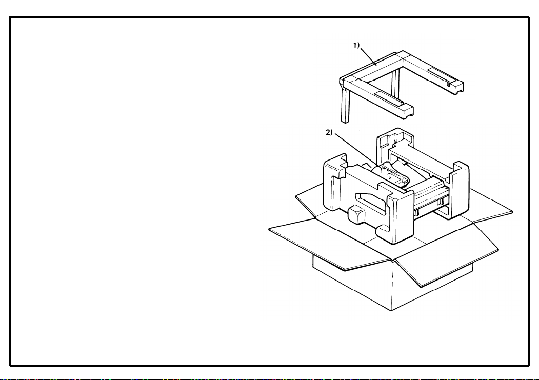
6-1. Unpacking Procedure
6-1
1. Open the shipping box.
2. Take out the mounting base; then, take out
the sorter together with the cushion blocks.
3. Take off the cushion blocks and take the
sorter out of the plastic bag.
1) Mounting Base
2) Accessories
February 1, 1986
Page 3
February 1, 1986
6-2
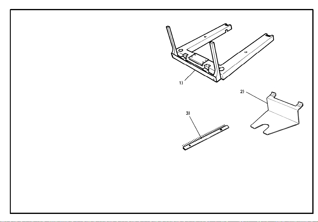
6-2. Accessory Check
Check the quantity and condition of the accessories
in the box according to the New Equipment Condition
Report.
1.
Mounting Base . . . . . . . . . . . . . . . . . . . 1pc
2.
Proof Tray . . . . . . . . . . . . . . . . . . . . . . 1pc
3.
Antistatic Brush . . . . . . . . . . . . . . . . . .
4.
Magnet . . . . . . . . . .. ........ . . . . ..1pc
Harness Bracket . . . . . . . . . . . . . . . . . .
5.
Mounting Lock . . . . . . . . . . . . . . . . . ..2pcs
6.
7.
Short Screw . . . . . . . . . . . . . . . . . . . . .
(Incl.1 Grounding Screw)
8.
Stepped Screw . . . . . . . . . . . . . . . . . . 1pc
9.
Long Screw . . . . . . . . . . . . . . . . . . . ..2pcs
10.
Bushing . . . . . . . . . . . . . . . . . . . . . . . . . 1pc
1 pc
1 pc
3 pcs
(Not used)
Page 4
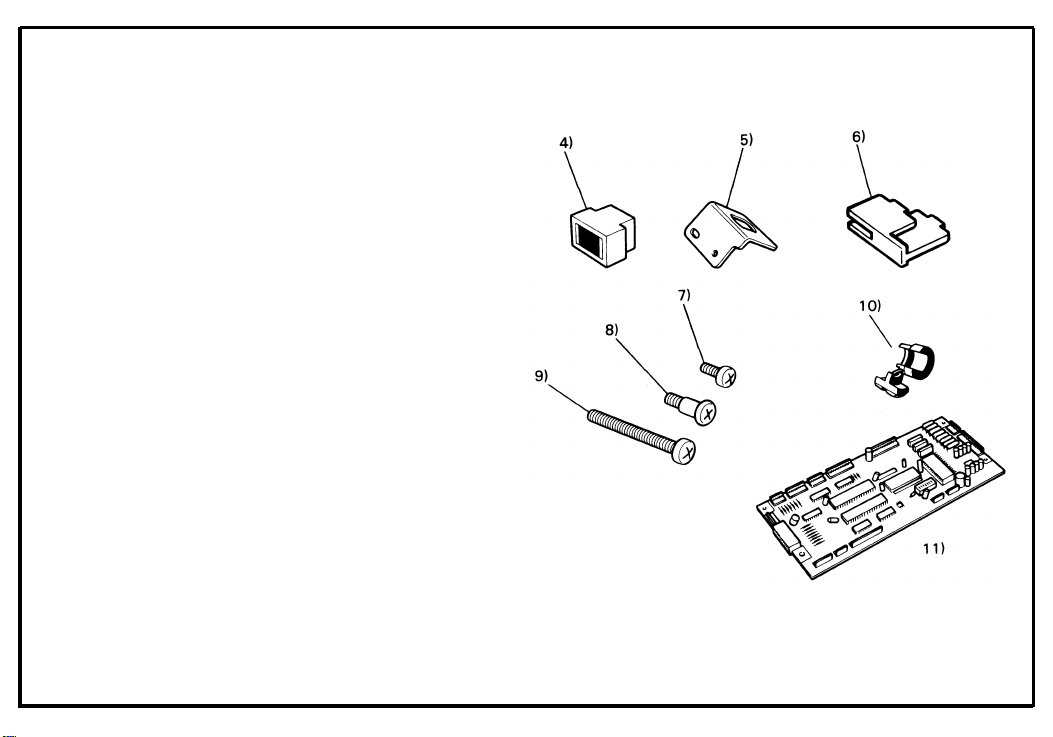
NOTE: To install the sorter on the FT2050 a sorter
compatible main board must be obtained.
These are available as options.
11 ) Interface Board Type C
February 1. 1986
6-3
Page 5
February 1, 1986
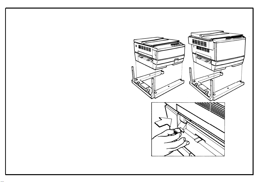
6-3. Installation procedure
1. Install the copier on the mounting base.
NOTE: Make sure that the legs rest securely
in the cutouts of the mounting base.
2. Install the magnet on the left cover as shown.
NOTE: Place the magnet in the bottom right-
hand corner of the cutout.
6-4
Page 6
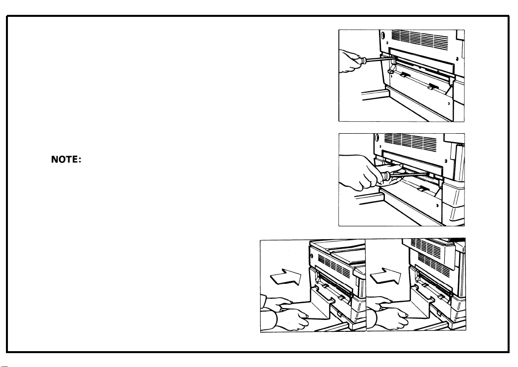
3. Remove the two screws on the exit cover.
6-5
4. Install the antistatic brush.
Use a screw from step 3 in the left
side and the accessory stepped screw
in the right side.
5. Install the proof tray where the copy tray normally fits.
February 1. 1986
Page 7
February 1, 1986
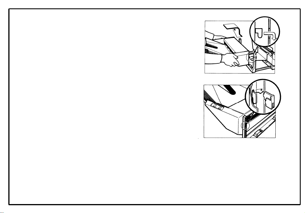
6. Insert the sorter hooks into the vertical posts
of the mounting base.
7. Secure the sorter hooks by installing the
mounting locks.
Separate procedures are needed to install the sorter
on the FT2050 and the FT2070. Follow the procedure from step 8 when installing the sorter on the
FT2050. Proceed to step 21 when installing the
sorter on the FT2070.
6-6
Page 8

8. Remove the rear cover (2 screws)
6-7
February 1, 1986
9. Move the slider to
slider lock release
the left by pressing
lever. Then, lower
the
the
10. Replace the main board with the sorter compatible main board (3 screws and 8 connectors).
Page 9

February 1, 1986
11. Remove the upper left cover (4 screws).
12. Remove the plastic cap from the docking hole
of the upper left cover.
13. Install the harness bracket (2 screws).
Page 10

14.
Thread the sorter harness through the docking
hole and the harness bracket.
15.
The sorter harness has two harness bands
used as markers.
Place the bushing on the
sorter harness just behind the first harness
band from the connector. Secure the bushing in the harness bracket.
February 1, 1986
16.
Secure both ground
bracket(1screw).
wires to the rear cover
/
I /
l
6-9
Page 11

February 1, 1986
17. Couple the connector to CN114 on the main
board.
18. Reassemble the copier.
19. Slide the sorter to its normal position.
20. Check the operation in all modes.
This completes the sorter installation
FT2050
on the
6-10
Page 12

21. Open the front cover.
6-11
22. Move the slider to the center and push down
the release lever to open the top unit.
23. Remove the release lever (1 E-ring).
Page 13

February 1.1986
24. Remove the inner cover (2 screws).
25. Lower the top unit.
26. Move the slider fully to the right, then remove
the upper left cover (4 screws).
Page 14

27. Remove the rear cover (2 screws).
28. Install the harness bracket (2 screws).
29. Remove the plastic cap from the docking hole
of the upper left cover.
February 1, 1986
6-11-2
Page 15

February 1, 1986
30. Thread the sorter harness through the docking
hole and the harness bracket.
31. The sorter harness has two harness bands
used as markers. Place the bushing on the
sorter harness just behind the second harness
band from the connector. Secure the bushing in the harness bracket.
32. Secure the sorter harness into the three wire
saddles which are mounted on the left underside of the optics unit.
6-11-3
Page 16

33.
Run the sorter harness above the total counter
bracket, and couple the connector to CN114
on the main board.
34.
Secure the ground wire to the front machine
plate.
35.
Reassemble the copier.
36.
Slide the sorter to its normal position.
37.
Check the operation in all modes.
This completes the sorter installation on the
FT2070.
6-11-4
Page 17

6-4. Preparation for Transporting the Sorter
Before moving the sorter from its place of installation, be sure to prepare it for transportation as
follows.
The sorter may be badly damaged if it is
moved without proper preparation.
1.
If the bins are not at the home position, turn on
the main switch of the copier to move the bins
to the home position.
2.
Secure the bins with strips of tape as shown
to the right.
Remove the sorter from the copier. (Refer to
3.
the “installation Procedure (Sorter)” Section.)
CAUTION: * When removing and transporting
the sorter, be careful not to incline it
to prevent the bins from being dislocated.
6-12
Page 18

6-5. Roller Drive Belt Replacement
1.
Loosen the screws, slide the front and rear
covers toward exit end of the sorter, and then
remove them.
2.
Remove the top cover.
Remove the top stay.
3.
NOTE: * Be sure that the short edge of the top
stay is facing the exit side of the sorter
when re-installing.
4. Lift the upper paper guide up and out of position.
NOTE: * Be careful not to damage the home posi-
tion switch actuator when reassembling.
5.
Lift the lower paper guide out of position and
turn it over to remove the roller drive belt.
Remove the transfer wheel, spacer, pin and
6.
bushing (1 C-ring).
August 1, 1985
7.
Slide the wheel shaft towards the front and
remove the roller drive belt.
Page 19

August 1, 1985
6-6. Bin Guide Lubrication
1.
Remove the lower paper guide. (See “Roller
Drive Belt Replacement” section.)
2.
Remove all bins from the bin guides.
3.
Apply Grease 501 to the grooves of
guides.
NOTE: * These are three-kinds of bin.
Therefore, when installing the bins, be
sure that the bins are installed in the correct order.
the bin
6-14
Page 20

Page 21

 Loading...